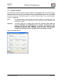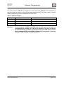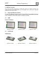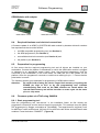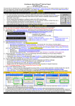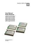
1
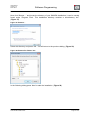
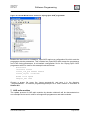
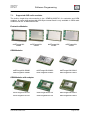
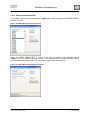
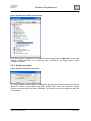
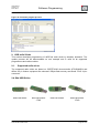
User Manual Software Programming For Radio Modules and USB Sticks by dresden elektronik Document Version V1.5 2013-08-21 User Manual Version 1.5 2013-08-21 Software Programming Table of contents 1. Firmware Files ................................................................................................................. 6 2. Programming tools .......................................................................................................... 6 2.1.AVR Studio 4.19 ....................................................................................................... 6 2.2.AVR Studio 5 ............................................................................................................ 7 2.3.Atmel Studio 6 .......................................................................................................... 7 2.4.AVRdude .................................................................................................................. 8 2.4.1. Using AVRdude without AVR Studio (stand-alone) ..................................... 8 2.4.2. Using AVRdude together with AVR Studio ................................................ 11 2.5.SAM-BA 2.12 .......................................................................................................... 12 2.6.JLinkCommander.................................................................................................... 12 2.7.Open OCD .............................................................................................................. 13 3. Programmer .................................................................................................................. 13 3.1.AVRDRAGON......................................................................................................... 13 3.2.JTAGICEmkII .......................................................................................................... 14 3.3.AVRISP .................................................................................................................. 14 3.4.SAM-ICE................................................................................................................. 14 3.5.OpenOCD based programmers .............................................................................. 14 4. Electrical programmer connections ................................................................................ 14 4.1.JTAG 10 pin............................................................................................................ 15 4.2.Small JTAG 10 pin .................................................................................................. 15 4.3.JTAG 20 pin............................................................................................................ 16 4.4.ISP 6 pin ................................................................................................................. 16 4.5.JTAG Adapter ......................................................................................................... 17 4.6.SAM-ICE Adapter ................................................................................................... 17 4.7.USB interface ......................................................................................................... 17 5. Platform and Baseboard ................................................................................................ 18 5.1.Custom platforms.................................................................................................... 18 5.2.Platforms by dresden elektronik: ............................................................................. 19 www.dresden-elektronik.de Page 2 of 61 User Manual Version 1.5 2013-08-21 6. Software Programming Drivers ........................................................................................................................... 22 6.1.AT91-USB-to-Serial-Converter ............................................................................... 22 6.1.1. Driver Installation in Windows XP .............................................................. 22 6.1.2. Driver Installation in Windows Vista and 7 ................................................. 25 6.2.J-Link Driver for SEGGER SAM-ICE ....................................................................... 29 6.3.Jungo USB Driver for AVR programmer.................................................................. 29 6.4.Drivers and configuration of OpenOCD Programmer .............................................. 29 7. AVR radio modules........................................................................................................ 30 7.1.Supported AVR radio modules................................................................................ 31 7.2.Required hardware and electrical connections ........................................................ 32 7.3.Preparation for programming .................................................................................. 32 7.4.Firmware update via JTAG using AVR Studio 4 ...................................................... 32 7.4.1. Start programming tool .............................................................................. 32 7.4.2. Define microcontroller ............................................................................... 34 7.4.3. Update firmware ........................................................................................ 35 7.5.Firmware update via JTAG using AVRdude ............................................................ 35 7.6.Firmware update via JTAG using Atmel Studio 6 .................................................... 37 7.6.1. Start programming tool .............................................................................. 37 7.6.2. Define tool, device and interface ............................................................... 38 7.6.3. Update firmware ........................................................................................ 39 7.7.Firmware update via ISP using AVR Studio 4.19 .................................................... 39 7.7.1. Start programming tool .............................................................................. 39 7.7.2. Define microcontroller and programming mode ......................................... 40 7.7.3. Update firmware ........................................................................................ 41 7.8.Fuses...................................................................................................................... 42 7.9.Lock Bits ................................................................................................................. 44 8. ARM radio modules ....................................................................................................... 45 8.1.Supported ARM radio modules ............................................................................... 45 8.2.ARM7 ..................................................................................................................... 45 8.3.CORTEX-M3 .......................................................................................................... 45 8.4.Required Hardware and electrical connections ....................................................... 46 8.5.Preparation for programming .................................................................................. 46 8.6.Firmware update via JTAG using SAM-BA ............................................................. 46 www.dresden-elektronik.de Page 3 of 61 User Manual Version 1.5 2013-08-21 Software Programming 8.6.1. Start programming tool .............................................................................. 46 8.6.2. Update procedure ..................................................................................... 47 8.7.Firmware Update via JTAG using JLink Commander .............................................. 47 8.7.1. Start programming tool .............................................................................. 47 8.7.2. Update procedure ..................................................................................... 48 8.8.Firmware Update via JTAG using OpenOCD .......................................................... 49 8.8.1. Flashing deRFarm7 radio module ............................................................. 49 8.8.2. Flashing deRFsam3 radio module ............................................................. 51 8.9.Firmware update via USB using SAM-BA ............................................................... 52 8.9.1. Preparation ............................................................................................... 52 8.9.2. Update procedure ..................................................................................... 53 9. USB radio Sticks............................................................................................................ 54 9.1.Supported radio sticks ............................................................................................ 54 9.2.Required Hardware and electrical connection ......................................................... 55 9.3.Firmware update via JTAG ..................................................................................... 55 9.3.1. Preparation for programming..................................................................... 55 9.3.2. Transferring firmware ................................................................................ 57 9.4.Firmware update via USB ....................................................................................... 57 9.4.1. Connecting SAM-BA to the USB stick ....................................................... 58 9.4.2. Erase USB stick ........................................................................................ 58 10. Manufacturing data ........................................................................................................ 59 11. References .................................................................................................................... 60 www.dresden-elektronik.de Page 4 of 61 User Manual Version 1.5 2013-08-21 Software Programming Document history Date Version Description 2011-09-29 1.0 Initial version 2011-11-14 1.1 Added pictures for driver installation 2012-01-05 1.2 Updated to SAM-BA 2.11 2012-05-31 1.3 Updated driver installation 2013-04-15 1.4 Including new sections: Firmware files, Programming tool, electrical connections, programmer, fuse settings, NV-RAM, Erase-Pin Addition of new devices: AVR radio modules ARM7 radio modules CORTEX-M3 radio modules Updated to SAM-BA 2.12 2013-08-21 1.5 www.dresden-elektronik.de Update section ‘Manufacturing Data’ and ‘References’ Page 5 of 61 User Manual Version 1.5 2013-08-21 Software Programming Overview This Manual shows different ways how to update the firmware on radio modules and USB radio sticks from dresden elektronik. The update will be described and executed with common programming tools. The update process examples are demonstrated on three different microcontroller architectures: Atmel AVR: ATMEGA128RFA1 and ATMEGA256RFR2 Atmel ARM7: AT91SAM7X512 Atmel CORTEX-M3: ATSAM3S4A and ATSAM3S4B 1. Firmware Files The programming tools for AVR microcontrollers described and used within this document require a ‘hex’-file for firmware updates of the internal flash and EEPROM. The file extension is ‘hex’. Other tools might accept other file formats as well. The tool used to transfer the firmware to the internal flash of microcontrollers with ARM architecture use two file formats. Depending on the tool either ‘hex’-files and ‘bin’-files are used. The required firmware file format is usually generated after the compilation and linking of the source code files and objects by some post processing tool of the tool chain used for compilation. To transfer the firmware to the internal flash or EEPROM of any microcontroller a microcontroller specific programmer and programming tool are required. 2. Programming tools For AVR and ARM architectures freeware tools but also licensed development environments (IDE) and tools exist on the market. Often the microcontroller manufacturer offers own programming tools and programmers. The features and the usability of those tools may vary vastly. The customer can choose the tool that fulfills the requirements for prize, performance, stability and usability best. The programming tools described in this manual are all freeware but may require a registration for download. 2.1. AVR Studio 4.19 The main version is obsolete but still prevailed in the AVR community. The AVR Studio 4 was replaced by ‘AVR Studio 5’ and as well as ‘Atmel Studio 6’, which is the actual programming tool for AVR and ARM microcontrollers by Atmel. Programming tool: AVR Studio 4 Version: 4.19 Tested with programmers: JTAGICEmkII, AVRDRAGON, AVRISPmkII Supported device targets: AVR radio modules Tested on OS: WinXP 32-bit, Win7 32-bit www.dresden-elektronik.de Page 6 of 61 User Manual Version 1.5 2013-08-21 Software Programming Download: http://www.Atmel.com/tools/AVRSTUDIO4.aspx (Registration necessary) Setup and Start: Execute the file ‘AvrStudio419Setup.exe’ and confirm the license agreement. Choose the install destination of AVR Studio 4 and install the AVR Jungo USB driver. After completion of the setup start the application. 2.2. AVR Studio 5 This tool will not be supported because of the replacement with Atmel Studio 6. 2.3. Atmel Studio 6 Atmel Studio 6 is a software tool with an integrated IDE for writing, debugging and deploying code to the device target. AVR and ARM architecture will be both supported. Programming tool: Atmel Studio 6 Version: 6.0 build 1996 Tested with programmers: JTAGICEmkII AVRDRAGON, AVRISPmkII, SAM-ICE Supported device targets: AVR / CORTEX-M3 radio modules Tested on OS: WinXP 32-bit, Win7 32-Bit Download: http://www.Atmel.com/tools/Atmelstudio.aspx (Registration necessary) Setup and Start: Execute the file ‘as6installer-6.0.1996-net.exe’ and confirm the license agreement. The setup requires Microsoft .NET Framework 4.0 Full Profile, Microsoft Visual Studio Isolated Shell 10.0 and Atmel USB Driver. The package includes these parts and will install them if necessary. Select the install destination of Atmel Studio 6 and continue the setup. After completion start the application. Connect the preferred programmer to the USB port. Note: If the programmer cannot be installed correctly, it could be necessary to install the ‘Jungo’ USB driver manually. Refer to the following Atmel support request: http://support.Atmel.com/bin/customer.exe?=&action=viewKbEntry&id=1343 The install file ‘wdreg.exe’ must be executed in a command window with the extension: wdreg.exe -log Atmelusb.log -inf windrvr6.inf install www.dresden-elektronik.de Page 7 of 61 User Manual Version 1.5 2013-08-21 Note: Software Programming In the most cases, the used programmer needs a firmware upgrade. This will be done automatically by Atmel Studio 6. If a programmer communication error occurs, it is also possible to do a manual firmware upgrade of the programmer. Execute the file ‘avrfwupgrade.exe’ in the install directory ‘…\Atmel\Atmel Studio 6.0\extensions\Utils\bin\’. Type the command below to get the syntax information: avrfwupgrade.exe –h 2.4. AVRdude Programming tool: AVRdude Version: 5.10 Tested with programmers: AVRDRAGON Supported device targets: AVR based radio modules Tested on OS: WinXP 32Bit Download: http://savannah.nongnu.org/projects/avrdude http://winavr.sourceforge.net Setup and Start: The AVRdude is either available in source code, which must compiled before usage (see first download link) but also available as binary as part of the WinAVR package. WinAVR is a compiler collection for AVR controller. The AVRdude does not need an installation, as it is a single executable used via command line. Using the AVRdude beside an already installed Atmel AVR Studio, some steps have to be done previously, as the AVR Studio installs the Jungo driver which is the USB driver system for all the programmers supported by AVR Studio. Unfortunately AVRdude is not able to use the Jungo driver to down-/upload application firmware. Therefore a filter USB driver is necessary. This is offered by the libusbwin32 driver software (the name should not be confused - this drivers also works under 64 Bit Windows systems). 2.4.1. Using AVRdude without AVR Studio (stand-alone) After installation of WinAVR, it is necessary to install the programmer drivers. In this example, the AVRDRAGON is used. The WinAVR package does not deliver suitable driver files for the AVRDRAGON. The following steps show an inf-file creation for the programmer as a libusb-win32 device. www.dresden-elektronik.de Page 8 of 61 User Manual Version 1.5 2013-08-21 Software Programming Execute ‘inf-wizard.exe’ (Figure 1) in the WinAVR install directory ‘…\utils\libusb\bin\’. Figure 1: Execute inf-wizard.exe Choose the AVRDRAGON programmer. (Figure 2) Figure 2: Select the device The device inf-file named ‘avrdragon’ will be created in the following path. (Figure 3) Figure 3: inf-file creation www.dresden-elektronik.de Page 9 of 61 User Manual Version 1.5 2013-08-21 Software Programming After the wizard is finished, the programmer can be installed. Update the programmer driver in the windows device manager and choose the created inf-file ‘avrdragon’. (Figure 4) Figure 4: inf-file path The AVRDRAGON must now be displayed as libusb-win32-device. (Figure 5) Figure 5: LibUSB-Win32-Device A firmware programming example for a radio module is described in Section 7.5. www.dresden-elektronik.de Page 10 of 61 User Manual Version 1.5 2013-08-21 Software Programming 2.4.2. Using AVRdude together with AVR Studio If the AVRdude and another AVR tool installation will be installed on the same operating system, a libusb-win32 filter must be established before. This will enable a proper functionality of the Jungo USB driver by AVR tools and the libusb-win32 driver by AVRdude. The libusb-win32 package offers the application package itself and the libusb-win32-develfilter-x.x.x.x.exe file. It must be downloaded from this link (the latest release should be taken): http://sourceforge.net/projects/libusb-win32/files/libusb-win32-releases/ After the AVRDRAGON is properly connected to the PC and the ‘libusb-win32-devel-filterx.x.x.x.exe’ install process is finished, a filter installer dialog, as illustrated in Figure 6 will appear. Figure 6: libusb-win32 filter Select the AVRDRAGON and the button ‘Install’ will create the USB filter driver (Figure 7). Figure 7: Select device Now the AVRDRAGON will be displayed correctly in the system device manager and can be used with AVRdude and an AVR tools installation like AVR Studio. A radio module firmware programming example is described in Section 7.5. www.dresden-elektronik.de Page 11 of 61 User Manual Version 1.5 2013-08-21 2.5. Software Programming SAM-BA 2.12 SAM-BA is an official Atmel in-system programming tool for ARM microcontrollers by Atmel. Programming tool: SAM-BA Version: 2.12 Tested with programmers: SAM-ICE Supported device targets: ARM7 and CORTEX-M3 radio modules Tested on OS: WinXP 32-Bit Download: http://www.Atmel.com/tools/AtmelSAM-BAINSYSTEMPROGRAMMER.aspx Setup and Start: Execute the file ‘sam-ba_2.12.exe’ and confirm the license agreement. Choose the install destination of SAM-BA and connect the preferred programmer to the USB port. After completion of the setup start the application. 2.6. JLinkCommander The JLinkCommander is a console based programming tool for ARM microcontrollers. It is especially useful for automated firmware updates with batch-files. Programming tool: JLinkARM V.4.60 Version: Tested with programmers: SAM-ICE Supported device targets: ARM7 and CORTEX-M3 radio modules Tested on OS: WinXP 32-bit Download: http://www.segger.com/jlink.html Setup and Start: Execute the file ‘Setup_JLinkARM_V460a.exe’ and confirm the license agreement. Choose the install destination of JLinkARM and connect the preferred programmer to the USB port. After completion of the setup start the application www.dresden-elektronik.de Page 12 of 61 User Manual Version 1.5 2013-08-21 2.7. Software Programming Open OCD OpenOCD is a low-budget programming tool for ARM-based and MIPS microcontrollers. It hooks up to GDB and Eclipse, and has good support for the low-cost FTDI based USB adapters. OpenOCD is either invoked on the command line or runs in background as a daemon (there is no graphical user interface). It can be used for flash programming as well as debugging and ships with an integrated GDB server. There is a large community using and permanently improving OpenOCD. For details, please visit the project website: http://openocd.sourceforge.net/ Programming tool: openOCD (Open On-Chip Debugger) Version: 0.6.1 Tested with programmers: ICprog OpenOCD Supported device targets: ARM7 and CORTEX-M3 radio modules Tested on OS: WinXP 32-bit Download: http://sourceforge.net/projects/openocd/ (sources) http://www.freddiechopin.info/en/download/category/4-openocd (pre-compiled)1 Setup and Start: Extract and compile according to the given instructions if the source version is used or extract to a chosen directory for pre-compiled version. Interconnect the programmer with the PC. 3. Programmer This section lists programmers for AVR and ARM microcontrollers. There are far more programmers available on the market, but only the described below are tested, used and recommended by dresden elektronik. dresden elektronik does not provide or sell any of the listed programmers. Please refer to your local distributor for electrical components. 3.1. AVRDRAGON The AVRDRAGON is a simple low-cost programmer by Atmel. It has a native USB interface and supports JTAG, ISP and High-Voltage-Parallel programming. Comprehensive information can be found in the web. Default interfaces: JTAG 10 Pin (see Section 4.1) and ISP 6 Pin (see Section 4.4) The official site is http://www.atmel.com/tools/avrdragon.aspx 1 Recommended version. www.dresden-elektronik.de Page 13 of 61 User Manual Version 1.5 2013-08-21 3.2. Software Programming JTAGICEmkII The AVR JTAGICEmkII is a mid-range programmer tool for Atmel AVR devices with on-chip debugging, tracing and device programming capabilities. Default interface: JTAG 10 Pin (see Section 4.1) The official site is http://www.atmel.com/tools/AVRJTAGICEMKII.aspx A JTAGICEmkII target cable matching adapter for small 1.27mm pin header JTAG interfaces is available from dresden elektronik online store as accessories. 3.3. AVRISP The AVRISP can program 8-Bit AVR microcontrollers with ISP or PDI interfaces. Default interface: ISP 6 Pin (see Section 4.4) The official site is http://www.atmel.com/tools/AVRISPMKII.aspx 3.4. SAM-ICE The SAM-ICE is a JTAG programmer designed for Atmel SAM3 and SAM7 ARM-based microcontrollers. It only supports Atmel devices. Default interface: JTAG 20 Pin (see Section 4.3) The official site is http://www.atmel.com/tools/ATMELSAM-ICE.aspx 3.5. OpenOCD based programmers OpenOCD programmers are designed to interface with ARM-based MCUs (ARM7, CortexM3). There is nothing like a unitary OpenOCD programmer, but there are plenty of them. The programmers differ in look, size, price, their PC interface (USB/RS232) as well as implementation of their JTAG connector and optional additional interface. A good overview over common programmers can be found under: http://openocd.sourceforge.net/doc/html/Debug-Adapter-Hardware.html Default interface: n/a (programmer dependent, but JTAG 10 Pin / JTAG 20 Pin are common) Official site: n/a (programmer dependent) 4. Electrical programmer connections The JTAG interfaces of AVR and ARM boards follow a semi-standard pin configuration to allow the usage of different programmers. For AVR boards the 10 pin connector described in Section 4.1 is the most commonly used; for ARM boards the 20 pin connector as described in Section 4.3. Note: The described JTAG interface connections are for dresden elektronik devices and may vary slightly from the standard pin configuration. Those variations are marked by a ‘blue italic’ pin description. www.dresden-elektronik.de Page 14 of 61 User Manual Version 1.5 2013-08-21 Note: 4.1. Software Programming dresden elektronik extensions are always designed as additional feature and do not prevent the usage of standard programmers. JTAG 10 pin The most common JTAG interface connector for AVR microcontrollers is a 10 pin 100 mil header. Some ARM programmers like OpenOCD use the same interface. The signal description is shown in Figure 8. Pin 1: TCK Pin 3: TDO Pin 5: TMS Pin 7: VCC Pin 9: TDI Figure 8: 10 pin JTAG Pin 2: GND Pin 4: VCC Pin 6: RESET Pin 8: n.c. Pin 10: GND The 10 pin header is supported by a lot of programmers, such as: AVRDRAGON by Atmel JTAGICEmkII by Atmel ICprog OpenOCD by In-Circuit AVR-JTAG by OLIMEX 4.2. Small JTAG 10 pin The small JTAG interface connector for microcontrollers is a 10 pin 50 mil header. This connector is preferred for small baseboards by dresden elektronik. The signal description is shown in Figure 9. The connector features the UART signals RXD and TXD additionally. Pin 1: TCK Pin 3: TDO Pin 5: TMS Pin 7: VCC Pin 9: TDI Figure 9: Small 10 pin JTAG Pin 2: GND Pin 4: VCC Pin 6: RESET Pin 8: RXD Pin 10: TXD The small 10 pin header needs an adapter to connect it with the programmer: JTAG Adapter by dresden elektronik and JTAGICEmkII programmer (for a picture of the adapter see Section 3.2) SAM-ICE Adapter by dresden elektronik and SAM-ICE programmer You can also refer to Section 4.5 and 4.6 for further information about the adapters. www.dresden-elektronik.de Page 15 of 61 User Manual Version 1.5 2013-08-21 4.3. Software Programming JTAG 20 pin A 20 pin 100 mil JTAG interface connector is often used for ARM microcontrollers. The signal description is shown in Figure 10. Pin 1: VCC Pin 3: n.c. Pin 5: TDI Pin 7: TMS Pin 9: TCK Pin 11: GND Pin 13: TDO Pin 15: RESET Pin 17: n.c. Pin 19: n.c. Note: Figure 10: 20 pin JTAG Pin 2: VCC Pin 4: GND Pin 6: GND Pin 8: GND Pin 10: GND Pin 12: GND Pin 14: GND Pin 16: GND Pin 18: GND Pin 20: GND depending on the programmer, it is necessary to place pull-up resistors to VCC on the signals RESET, TDI, TMS and TCK. We recommend 100 k ohms. The 20 pin header programmer is supported for example by: SAM-ICE by SEGGER ARM-JTAG by OLIMEX ICprog OpenOCD by In-Circuit 4.4. ISP 6 pin For serial programming interfaces of AVR microcontrollers a 6 pin 100 mil header is often used. The signal description is shown in Figure 11. Pin 1: PDO Pin 3: SCK Pin 5: RESET Figure 11: 6 pin ISP Pin 2: VCC Pin 4: PDI Pin 6: GND The 6 pin header programmer is supported for example by: AVRISP by Atmel AVRDRAGON by Atmel www.dresden-elektronik.de Page 16 of 61 User Manual Version 1.5 2013-08-21 4.5. Software Programming JTAG Adapter The JTAG Adapter works in connection with JTAGICEmkII programmer by Atmel. The programmer has a 30 pin flat cable with a default 10 pin 100 mil adapter. The default adapter must be replaced by the dresden elektronik JTAG adapter. The flat cable is mechanically fixed in the 30 pin socket and can be manually unlocked. Further information: https://shop.dresden-elektronik.de/accessories/adapter/jtag-adapter.html 4.6. SAM-ICE Adapter The SAM-ICE Adapter is useful in connection with the SAMICE programmer via the 20 pin 100 mil socket and the programming of USB stick device targets by dresden elektronik. The small 10 pin 50 mil JTAG connector features additionally two UART signals (RXD and TXD, see Section 4.2), which can be tapped on the 6 pin 100 mil header. For direct connection to a host PC or laptop, an assembled level-shifter circuit is available with a suitable 9 pin Sub-D socket. Alternatively, a custom level-shifter can be connected to the 6 pin header. Further information: https://shop.dresden-elektronik.de/accessories/adapter/sam-ice-adapter.html 4.7. USB interface The Atmel ARM7 and CORTEX-M3 microcontroller have an internal native USB controller. They still need external components for proper functionality. Figure 12 shows a schematic part from a native USB interface. Beside a USB header an and optional diode array for line protection, the necessary parts are the 1k5 pull-up resistor ‘R30’ on ‘USBDP’, the 330k pulldown resistors ‘R35’ and ‘R36’ on ‘USBDP’ and ‘USBDM’ and the low-pass network on ‘USBDP’ and ‘USBDM’, consisting of 27R resistors ‘R31’ and ‘R32’ and 15pF capacitors ‘C28’ and ‘C29’. www.dresden-elektronik.de Page 17 of 61 User Manual Version 1.5 2013-08-21 Software Programming Figure 12: Native USB – external components 5. Platform and Baseboard The used radio module must be plugged or soldered to an appropriate platform or baseboard. In most cases this platform is a custom one. Section 5.1 includes the minimum requirements to establish a programming connection. Development platforms by dresden elektronik (Section 5.2) fulfill all requirements to update the firmware of the evaluation radio modules. 5.1. Custom platforms A custom platform needs the following minimum hardware requirements to establish a connection to the programmer. The header connection depends on the used programmer. Refer to Section 3 for recommended programmers. AVR radio modules 10 pin header for JTAG with correct signal configuration (see Section 4.1) or 6 pin header for ISP with correct signal configuration (see Section 4.4) ARM7 and CORTEX-M3 radio modules 20 pin header for JTAG with correct signal configuration (see Section 4.3) or 10 pin header for JTAG with correct signal configuration (see Section 4.1) www.dresden-elektronik.de Page 18 of 61 User Manual Version 1.5 2013-08-21 Note: 5.2. Software Programming Depending on the programmer, it might be necessary to place pull-up resistors to VCC on the signals RESET, TDI, TMS and TCK. We recommend 100k ohms. Platforms by dresden elektronik: Attention: The listed platforms by dresden elektronik support only the pluggable AVR and ARM7 evaluation radio modules. To use the smaller OEM radio module with these platforms, the radio modules must be soldered onto an appropriate adapter. Alternatively, the already pre-soldered adapter module combinations can be purchased from the dresden elektronik online store. deRFbreakout Board 10 pin and 20 pin JTAG connector All signals available on screw terminals Recommended for all radio modules Product information: https://shop.dresden-elektronik.de/development-boardsand-kits/development-boards/derf-breakout-board.html Datasheet: http://www.dresden-elektronik.de/ funktechnik/service/downloads/documentation/ deRFgateway 10 pin and 20 pin JTAG connector Ethernet support Recommended for ARM7 radio modules Product information: https://shop.dresden-elektronik.de/development-boardsand-kits/development-boards/gateway-for-arm.html User Manual and Datasheet: http://www.dresden-elektronik.de/ funktechnik/service/downloads/documentation/ www.dresden-elektronik.de Page 19 of 61 User Manual Version 1.5 2013-08-21 Software Programming deRFnode for AVR 10 pin and 20 pin JTAG connector FTDI USB support Recommended for AVR radio modules Product information: https://shop.dresden-elektronik.de/development-boardsand-kits/development-boards/node-arm-avr.html User Manual and Datasheet: http://www.dresden-elektronik.de/ funktechnik/service/downloads/documentation/ deRFnode for ARM 10 pin and 20 pin JTAG connector Native USB support Recommended for ARM7 and Cortex-M3 radio modules Product information: https://shop.dresden-elektronik.de/development-boardsand-kits/development-boards/node-for-arm-1.html User Manual and Datasheet: http://www.dresden-elektronik.de/ funktechnik/service/downloads/documentation/ deRFtoRCB Adapter Small 10 pin JTAG connector Recommended for AVR radio modules Converts any pluggable dresden elektronik radio module into a Radio Controller Board (RCB) form factor Product information: https://shop.dresden-elektronik.de/accessories/adapterderftorcb.html Datasheet: http://www.dresden-elektronik.de/ funktechnik/service/downloads/documentation/ www.dresden-elektronik.de Page 20 of 61 User Manual Version 1.5 2013-08-21 Software Programming deRFtoRCB Adapter plugged onto Sensor Terminal Board 10 pin and small 10 pin JTAG connector FTDI USB support Recommended for AVR radio modules Signals available on screw terminals Product information: https://shop.dresden-elektronik.de/development-boardsand-kits/development-boards/stb-sensor-terminalboard.html + User Manual and Datasheet: http://www.dresden-elektronik.de/ funktechnik/service/downloads/documentation/ www.dresden-elektronik.de Page 21 of 61 User Manual Version 1.5 2013-08-21 Software Programming 6. Drivers As most programmers and development boards use USB as communication interface and power supply, the installation of a suitable driver is required prior to the microcontroller firmware update. 6.1. AT91-USB-to-Serial-Converter The ‘AT91-USB-to-Serial-Converter’ is a boot loader, stored in the internal ROM of ARMbased Atmel microcontrollers. This ROM boot loader supports the firmware update via the microcontroller’s native USB interface. The installation process in Windows XP and Windows 7 is described in the two sections below. 6.1.1. Driver Installation in Windows XP The first time you plug the USB stick in the ‘Found New Hardware Wizard’ will pop up. Please select ‘No, not this time.’ and press ‘Next’. (Figure 13) Figure 13: Found New Hardware Wizard On the next screen choose ‘Install from a list or specific location (Advanced)’ and press ‘Next’. (Figure 14) Figure 14: Install from a specific location www.dresden-elektronik.de Page 22 of 61 User Manual Version 1.5 2013-08-21 Software Programming Select ‘Don’t search. I will choose the driver to install.’ and press ‘Next’. (Figure 15) Figure 15: Choose driver manually On the next dialog press the ‘Have Disk…’ button. (Figure 16) Figure 16: Select ‘Have Disk…’ Now click on ‘Browse…’ and locate the directory of your SAM-BA installation; it can be usually found under ‘Program Files’. This installation directory contains a subdirectory ‘drv’. Please select and enter this directory. (Figure 17) Figure 17: Choose location: Browse… www.dresden-elektronik.de Page 23 of 61 User Manual Version 1.5 2013-08-21 Software Programming The file ‘atm6124_cdc’ should pop up; select it and press the ‘Open’ button. (Figure 18) Figure 18: Locate File: atm6124_cdc.inf By pressing ‘OK’ now you will return again to the previous dialog. (Figure 19) Figure 19: Install from disk: Continue with ‘OK’ Now select the ‘AT91 USB to Serial Converter’ and press ‘Next’. The driver will be installed. (Figure 20) Figure 20: Continue with ‘Next >‘ www.dresden-elektronik.de Page 24 of 61 User Manual Version 1.5 2013-08-21 Software Programming If a message box ‘Driver is not digitally signed’ appears press ‘Continue anyway’. The wizard will finish the driver installation. Press ‘Finish’ to close the wizard. (Figure 21) Figure 21: Finish the installation After successful driver installation you will find the device under Ports (COM & LPT) in the device manager. (Figure 22) Figure 22: Successfully installed device 6.1.2. Driver Installation in Windows Vista and 7 If you plug in the USB stick for the first time, Windows will try to install any driver. This will usually fail and produces the following message. (Figure 23) Figure 23: Driver not found in Win7 or Vista www.dresden-elektronik.de Page 25 of 61 User Manual Version 1.5 2013-08-21 Software Programming To install the correct driver please open the Device Manager, which can be found under Control Panel > System > Device Manager. Here you will find an ‘Unknown device’ in ‘Other devices’. (Figure 24) Figure 24: Driver not found in Device Manager Select the ‘Unknown device’; open the context menu with a right mouse click. Select ‘Update Driver Software’ in the menu. (Figure 25) Figure 25: Update Driver Software… Now choose ‘Browse my computer for driver software’ on the next dialog. (Figure 26) Figure 26: Browse computer for driver software www.dresden-elektronik.de Page 26 of 61 User Manual Version 1.5 2013-08-21 Software Programming Now click ‘Browse…’ and locate the directory of your SAM-BA installation; it can be usually found under ‘Program Files’. This installation directory contains a sub-directory ‘drv’. (Figure 27) Figure 27: Browse… Select this directory and press ‘OK’. This will return to the previous dialog. (Figure 28) Figure 28: Browse For Folder: \drv In the following dialog press ‘Next’ to start the installation. (Figure 29) www.dresden-elektronik.de Page 27 of 61 User Manual Version 1.5 2013-08-21 Software Programming Figure 29: Continue with ‘Next’ If a Windows Security message pops up choose ‘Install this driver software anyway’. (Figure 30) Figure 30: Choose ‘Install this driver software anyway’ You will see the installation progress. Close the wizard after the installation is finished by pressing ‘Close’. (Figure 31) Figure 31: Successful installation of the driver After a successful driver installation you will find an ‘AT91 USB to Serial Converter’ in the Device Manager under the ports (COM & LPT). (Figure 32) www.dresden-elektronik.de Page 28 of 61 User Manual Version 1.5 2013-08-21 Software Programming Figure 32: Device displayed in the device manager 6.2. J-Link Driver for SEGGER SAM-ICE The ARM programmer ‘SAM-ICE’ by Segger needs the ‘J-Link’ driver. Follow the install instructions for the JLink Commander in Section 2.6. The J-Link drivers are included in the install package. After connecting the programmer to the PC, the SAM-ICE will be automatically recognized as J-Link device. 6.3. Jungo USB Driver for AVR programmer The AVR programmers JTAGICEmkII, AVRDRAGON and AVRISP need the Jungo USB driver, which is included in the AVR tools packages, like AVR Studio 4 or ATMEL Studio 6. Follow the instructions in Section 2.1 and/or 2.3. The connected AVR programmer will be recognized and installed automatically. 6.4. Drivers and configuration of OpenOCD Programmer Mostly the available programmers are based on FTDI RS232 USB adapters. OpenOCD contains drivers for the most common programmers, located in the directory ‚driver‘. The FTDI default drivers are not delivered with OpenOCD because of licensing issues. Instead the ‘libusb-win32‘ should be used. Install the drivers for the programmer. For example the ‘ICprog Open OCD’ programmer needs the ‘libusb-win32_ft2232_driver’. In case of doubt use the manufacturer’s drivers. If an error occurs install the libusb-filter driver. See Section 2.4.2 for further information. After proper driver installation the device manager should display entries for ‘libusb-win32’ devices. Figure 33 shows the entries for the ‘ICprog Open OCD’ programmer. Do not wondering about the two entries: they are generated by the used programmer. www.dresden-elektronik.de Page 29 of 61 User Manual Version 1.5 2013-08-21 Software Programming Figure 33: Libusb-Win32 Device entries for ‘ICprog Open OCD’ programmer Besides the device driver installation, OpenOCD requires a configuration file which sets the programmer device parameters. This includes how OpenOCD shall access the programmer and JTAG timing parameters. A minimalistic configuration file for the ‘ICprog Open OCD’ programmer which is used for this example looks as follows: #interface interface ft2232 ft2232_vid_pid 0x0403 0x6010 ft2232_layout ‘oocdlink’ #JTAG clock speed adapter_khz 1000 Choose a proper file name like ‘icprog_openocd.cfg’ and save it in the directory ‘./scripts/interface/’. A firmware programming example for a radio module is described in Section 8.8. 7. AVR radio modules The update process of AVR radio modules by dresden elektronik will be demonstrated on one example device and is valid for all supported programmers and radio modules. www.dresden-elektronik.de Page 30 of 61 User Manual Version 1.5 2013-08-21 7.1. Software Programming Supported AVR radio modules The built-in single-chip microcontroller is the ‘ATMEGA128RFA1’ for evaluation and OEM modules. A newer chip version with 256 kByte internal flash is only available in OEM radio modules with the ‘ATMEGA256RFR2‘. Evaluation Modules deRFmega12822A00 deRFmega12822A02 deRFmega12822C00 deRFmega12822C02 OEM Modules deRFmega128-22M00 deRFmega128-22M10 deRFmega128-22M12 deRFmega256-23M00 deRFmega256-23M10 deRFmega256-23M12 deRFmega128-22T00 deRFmega128-22T02 deRFmega128-22M13 deRFmega256-23T00 deRFmega256-23T02 deRFmega256-23M13 OEM Modules with adapter www.dresden-elektronik.de Page 31 of 61 User Manual Version 1.5 2013-08-21 7.2. Software Programming Required hardware and electrical connections A firmware update of an AVR radio module by dresden elektronik needs a few requirements that must be fulfilled: an AVR compatible programming tool (see Section 2), the AVR programmer (see Section 3), an available electrical connection (see Section 4) and the platform (see Section 5) 7.3. Preparation for programming At first ensure that the required programming tool and all drivers are installed on your workstation. Connect the platform or baseboard on which the AVR radio module is plugged or soldered to an appropriate power supply. Now, the preferred programmer must be connected to the workstation (in the most cases via USB) and the JTAG or ISP header on the platform. Often, the programmer connector or cable has a marking for pin ‘1’. Ensure that the polarization is correct. The following sections give examples for programming of AVR evaluation radio modules via JTAG and ISP. 7.4. Firmware update via JTAG using AVR Studio 4 7.4.1. Start programming tool This example shows a firmware update of a deRFmega128 radio module with AVR Studio 4.19. The programmer is an AVRDRAGON connected to the deRFnode platform by dresden elektronik. At first, follow the preparation of Section 7.3. Start the programming tool and quit the start-up screen. Select ‘TOOLS’ ‘PROGRAM AVR’ and press on ‘CONNECT…’. (Figure 34) Figure 34: AVR Studio 4.19 Start www.dresden-elektronik.de Page 32 of 61 User Manual Version 1.5 2013-08-21 Software Programming Select the used programmer platform and the connection port. In this example an AVRDRAGON via USB is used. Press on ‘CONNECT…’. (Figure 35) Figure 35: AVR Studio 4.19 Programmer selection The new window (Figure 37) offers a lot of program and setup functions for the used device: Main: microcontroller and programming mode selection Program: Update the internal flash or EEPROM. Alternatively use the ELF production file format. Fuses: set the fuses (see Section 7.8) Lock Bits: use lock bits to enable a write and read/write protection for the Boot Program section and Application Program Section of the internal Program Flash Memory (see Section 7.9) Advanced: Set the value of the Oscillator Calibration Byte HW Settings: Read out the target voltage; achieve a programmer firmware upgrade HW Info: programmer hardware revision and firmware version Auto: automate user defined device target program processes www.dresden-elektronik.de Page 33 of 61 User Manual Version 1.5 2013-08-21 Software Programming 7.4.2. Define microcontroller At first define the correct microcontroller (Figure 36). In this example the ATMEGA128RFA1 must be chosen. Figure 36: AVR Studio 4.19 choose device Press on ‘READ SIGNATURE’ to check if the chip ID matches the selected device (Figure 37). In the case of an error, check if the selected device is correctly defined and if the used hardware setup is OK. The main power supply must be switch on. Figure 37: AVR Studio 4.19 Signature read-out www.dresden-elektronik.de Page 34 of 61 User Manual Version 1.5 2013-08-21 Software Programming 7.4.3. Update firmware The new microcontroller firmware must be loaded into the internal flash. Go to the program tab and choose the hex file for the flash. Press on ‘PROGRAM’ and wait till the update process is done. The log history should show ‘Leaving programming mode…OK!’ (Figure 38). Now cycle the power of the device target to ensure a correct start of the microcontroller firmware. Note: To correctly flash a new firmware the device needs to be erased first. The AVR Studio 4 does this automatically if the ‘Erase before flash programming’ check box is active. Attention: A device erase for an AVR does erase the internals flash AND the internal EEPROM. The EEPROM stores valuable manufacturing data such as the devices MAC address. To prevent the erasure of the EEPROM content the fuse ‘EESAVE’ must be active. We therefore recommend checking the fuse settings before any firmware update. Figure 38: AVR Studio 4.19 Programming done 7.5. Firmware update via JTAG using AVRdude The AVRdude program supports a wide range of programmers. This section will only cover the AVRDRAGON programmer. If any other programmer is used, the parameter following below must be customized to meet the programmer’s condition. Type in the command listed below to get a list of all supported programmers. avrdude.exe –c/? In Table 1 all necessary parameters are listed to program the deRFmega modules from dresden elektronik. Further information and details about the AVRdude commands are available on the corresponding homepage. www.dresden-elektronik.de Page 35 of 61 User Manual Version 1.5 2013-08-21 Software Programming Table 1: AVRdude parameter Parameter -p <partno> Description the target device which to program -V Disable automatic verify check when uploading -P <port> The port where the programmer is connected to -c <programmer-id> The <programmer-id> identifies the selected programmer -U <mem>:<op>:<file>[:<format>] <op> down-/upload or verify the <file> to the specified memory <mem> location All the parameters could be hand over in one single line, as demonstrated in the example below. Using this line will program all dresden elektronik deRFmega128 radio modules with the Atmel AVRDRAGON programmer (Figure 39). Type in the following commands without line break and confirm with <ENTER>. avrdude.exe -p m128rfa1 -V -P usb -c dragon_jtag -U flash:w:’application.hex’ The firmware file ‘application.hex’ is located in the root directory, where AVRdude is executed. Note: To correctly flash a new firmware the device needs to be erased first. AVRdude does this automatically. Attention: A device erase for an AVR does erase the internals flash AND the internal EEPROM. The EEPROM stores valuable manufacturing data such as the devices MAC address. To prevent the erasure of the EEPROM content the fuse ‘EESAVE’ must be active. We therefore recommend checking the fuse settings before any firmware update. www.dresden-elektronik.de Page 36 of 61 User Manual Version 1.5 2013-08-21 Software Programming Figure 39: Firmware update via AVRdude 7.6. Firmware update via JTAG using Atmel Studio 6 7.6.1. Start programming tool This section shows a firmware update of a deRFmega128 radio module with Atmel Studio 6. The programmer is an AVRDRAGON connected to the deRFnode platform by dresden elektronik. At first, follow the preparation on Section 7.3 and start the programming tool ‘atmelstudio.exe’. Open the programmer menu by ‘TOOLS’ ‘DEVICE PROGRAMMING’. (Figure 40) Figure 40: Studio 6 Start www.dresden-elektronik.de Page 37 of 61 User Manual Version 1.5 2013-08-21 Software Programming 7.6.2. Define tool, device and interface At first define the used programmer on ‘TOOL’. In this case chose AVRDRAGON. The next step is the selection of the device target microcontroller, here: ATMEGA128RFA1. The connection interface is JTAG. (Figure 41) Figure 41: Studio 6 interface settings Press on ‘READ’ to check if the chip ID matches the selected device. In the case of an error, check if the selected device is correctly defined and if the used hardware setup is OK. The main power supply must be switch on. (Figure 42) Figure 42: Studio 6 device information www.dresden-elektronik.de Page 38 of 61 User Manual Version 1.5 2013-08-21 Software Programming 7.6.3. Update firmware The next step is the update process. Go to the entry ‘memories’ and define the new firmware file for the internal flash and press on button ‘PROGRAM’. It is useful to activate the checkboxes ‘Erase device’ and ‘Verify Flash’ before programming. After the programming process a positive result shows that the erasing, programming and verifying of the flash are OK. (Figure 43) Note: To correctly flash a new firmware the device needs to be erased first. The ATMEL Studio 6 does this automatically if the ‘Erase device’ check box is active. Attention: A device erase for an AVR does erase the internals flash AND the internal EEPROM. The EEPROM stores valuable manufacturing data such as the devices MAC address. To prevent the erasure of the EEPROM content the fuse ‘EESAVE’ must be active. We therefore recommend checking the fuse settings before any firmware update. Figure 43: Studio 6 Device Programming 7.7. Firmware update via ISP using AVR Studio 4.19 7.7.1. Start programming tool This section shows a firmware update of an AVR radio module with AVR Studio 4.19. The programmer is an AVRISPmkII connected to a custom platform with the required connection shown in Section 4.4. At first, follow the preparation on Section 7.3. Start the programming tool and quit the start-up screen. Select ‘TOOLS’ ‘PROGRAM AVR’ and press on ‘CONNECT…’. Select the used programmer platform and the connection port. In this example an AVRISPmkII via USB is used. Press on ‘CONNECT…’. (Figure 44) www.dresden-elektronik.de Page 39 of 61 User Manual Version 1.5 2013-08-21 Software Programming Figure 44: Select AVR programmer 7.7.2. Define microcontroller and programming mode At first define the correct microcontroller. In this example the ATMEGA128RFA1 must be chosen. Check if the ISP mode is active. The default ISP frequency is 125 kHz. Press on ‘READ SIGNATURE’ to check if the chip ID matches the selected device. (Figure 45) In the case of an error, check if the selected device is correctly defined and if the used hardware setup is OK. The main power supply must be switch on. Figure 45: Choose device, programming mode and ID read-out Note: The ISP frequency must always be below ¼ of the microcontroller clock speed. Therefore 125 kHz is the best choice for many fuse settings as it will operate with microcontroller clock speeds of 1 MHz and above. However, higher ISP frequency settings result in a faster firmware update. At very low ISP frequencies the programming of 64 kB can take many minutes. It is advisable to check the selected ISP frequency prior to any firmware update. www.dresden-elektronik.de Page 40 of 61 User Manual Version 1.5 2013-08-21 Software Programming 7.7.3. Update firmware The new microcontroller firmware must be loaded into the internal flash. Go to the program tab and choose the hex file for the flash. Press on ‘PROGRAM’ and wait till the update process is done. The log history should show ‘Leaving programming mode…OK!’ Now make a power on reset on the device target, to ensure a correct start of the microcontroller firmware. (Figure 46) Note: To correctly flash a new firmware the device needs to be erased first. The AVR Studio 4 does this automatically if the ‘Erase before flash programming’ check box is active. Attention: A device erase for an AVR does erase the internals flash AND the internal EEPROM. The EEPROM stores valuable manufacturing data such as the devices MAC address. To prevent the erasure of the EEPROM content the fuse ‘EESAVE’ must be active. We therefore recommend checking the fuse settings before any firmware update. Figure 46: Program device www.dresden-elektronik.de Page 41 of 61 User Manual Version 1.5 2013-08-21 7.8. Software Programming Fuses The fuses of an AVR microcontroller are important and depending on the customer application. The fuses can be changed in the programming tool with the programmer. (Figure 47) Figure 47: Fuse settings The ATMEGA128RFA1 has following fuses. The recommended settings are listed in Table 2. A detailed description is available in the microcontroller datasheet [1]. Table 2: Recommended fuse setting Fuses Recommended Description BODLEVEL VCC = 1.8 V Brown-Out trigger level defined MCU reset behavior on low supply voltage event like an empty battery OCDEN OFF On-Chip-Debug Enabled JTAGEN ON JTAG enabled SPIEN ON Serial Programing Interface enabled WDTON OFF Watch-Dog timer always on EESAVE ON Preserve EEPROM through chip erase cycle maintaining MAC-ID over firmware update BOOTSZ Boot flash size = 4096 words start address $F000 Select boot size = BOOTRST OFF Boot reset vector enabled CKDIV8 ON Divide clock by 8 internally CKOUT OFF Clock output at port E7 CKSEL_SUT Int. RC Osc. 6 CK + 65 ms Select clock source and start-up time www.dresden-elektronik.de Page 42 of 61 User Manual Version 1.5 2013-08-21 Software Programming The fuses listed in Table 2 are mapped into three fuse bytes (Table 3). The description of the fuse bytes are shown in the microcontroller datasheet [1]. They were used in console based programming tools like AVRdude to set the fuses. Table 3: Extend fuse bytes Fuse Bytes EXTENDED Setting 0xFE Description Extended fuse byte HIGH 0x91 Fuse High Byte LOW 0x62 Fuse Low Byte Attention: Deactivating the JTAGEN and SPIEN fuse will affect that no firmware reprogramming is possible via JTAG or ISP interface. This fact is valid for all evaluation radio modules by dresden elektronik. OEM radio modules have a dedicated TST pin available, which allows performing a firmware update via High-Voltage Programming Mode. www.dresden-elektronik.de Page 43 of 61 User Manual Version 1.5 2013-08-21 7.9. Software Programming Lock Bits The lock bits of a microcontroller allow the customer to protect the radio module against reading and/or writing the internal memory. Attention: The following settings can affect that the device target memory is never again readable or programmable! If memory protection is required, set the lock bits always after the final firmware programming process! Figure 48: Lock bits setting The default values of the lock bits and lock byte are listed in Table 4 and Table 5. Table 4: Lock fuses Fuse LB Default Setting No memory lock features enabled BLB0 No lock on SPM and LPM in Application Section BLB1 No lock on SPM and LPM in Boot Section Table 5: Lock bits Lock Byte LOCKBIT Setting 0xFF www.dresden-elektronik.de Description Lock bit byte Page 44 of 61 User Manual Version 1.5 2013-08-21 Software Programming 8. ARM radio modules This section describes programming of ARM radio modules by dresden elektronik. The update process will be demonstrated on one example and is valid for all supported programmers and radio modules. 8.1. Supported ARM radio modules The supported ARM radio modules are based on two different microcontrollers. At first the powerful ‘AT91SAM7X512’ ARM7-controller on evaluation radio modules and at last the lowpower ‘ATSAM3S4’ CORTEX-M3-controller on OEM radio modules. 8.2. ARM7 Evaluation Modules deRFarm7-25A00 8.3. deRFarm7-25A02 deRFarm7-15A02 deRFsam3-23M10-2 deRFsam3-23M10-3 CORTEX-M3 OEM Modules deRFsam3-13M10 www.dresden-elektronik.de Page 45 of 61 User Manual Version 1.5 2013-08-21 Software Programming OEM Modules with adapter deRFsam3-13T02 8.4. deRFsam3-23T02-2 deRFsam3-23T02-3 Required Hardware and electrical connections A firmware update of an ARM7 or CORTEX-M3 radio module by dresden elektronik needs a few requirements that must be fulfilled: an ARM compatible programming tool (see Section 2), the ARM programmer (see Section 3), an available electrical connection (see Section 4) and the platform (see Section 5) 8.5. Preparation for programming At first ensure that the required programming tool and all drivers are installed on your workstation. Connect the platform or baseboard on which the ARM radio module is plugged or soldered to an appropriate power supply. Now, the preferred programmer must be connected to the workstation (in the most cases via USB) and the JTAG header on the platform. Often the programmer connector or cable has a marking for pin ‘1’. Ensure that the polarization is correct. The following section gives examples for programming of ARM radio modules. Attention: 8.6. Be careful with erasing the device target flash memory via pulling the ERASE pin high to VCC or by the programming tool. Valuable manufacturing data such as the MAC address are saved within the internal flash memory and will be lost after an erase cycle via the erase pin or a chip erase. Firmware update via JTAG using SAM-BA 8.6.1. Start programming tool Start the programming tool ‘sam-ba.exe’ in the installation folder. At first choose the programmer connection and the device target microcontroller. This example uses the SAMICE programmer by Segger, selectable as ‘\jlink\ARM0‘. The target board is ‘at91sam7x-ek’ for deRFarm7 radio modules and ‘rf231usb-rd’ for deRFusb radio sticks and deRFsam3 radio modules. Press the button ‘CONNECT’. (Figure 49) www.dresden-elektronik.de Page 46 of 61 User Manual Version 1.5 2013-08-21 Software Programming Figure 49: Choose connection and device 8.6.2. Update procedure A new window appears. The firmware must be load into the internal flash. Choose the firmware file with the ‘Send File Name’ browse button and press the ‘SEND FILE’ button. After a successful update process, the script ‘Boot from Flash (GPNVM1)’ must be executed. This will result in the GPNVM Bit is set to 1 (Figure 50). The target device will now start out of the internal flash memory after a power-on reset. Otherwise, the microcontroller will start the internal ROM boot loader again after a power-on reset and the programmed firmware will not be run. Figure 50: SAM-BA update Close the SAM-BA tool and perform a power cycle on the target. 8.7. Firmware Update via JTAG using JLink Commander The following procedure describes the flashing of a generated binary firmware file into the deRFsam3 radio module. Follow the preparation steps in Section 8.5. 8.7.1. Start programming tool At first start ‘JLink.exe’. A console window will open and the JLink Commander automatically searches the SAM-ICE programmer and identifies the connected microcontroller. Figure 51 www.dresden-elektronik.de Page 47 of 61 User Manual Version 1.5 2013-08-21 Software Programming Figure 51: JLink Start-up 8.7.2. Update procedure Type in the commands of Table 6 and execute each of them with <ENTER>: Table 6: Update command procedure Step Command h 1 Description Halt the ARM core 2 r Reset the target 3 Speed 1000 Set the JTAG speed to 1000 kHz 4 exec Device AT91SAM3S4A Selects the device target microcontroller 5 loadbin ‘C:\application.bin’ 0x00000000 Load binary file into target memory 6 h Halt the ARM core 7 r Reset the target 8 g Start the ARM core 9 q Quit JLINK.exe Now the binary is flashed into the microcontroller and the application is running. The syntax of the used commands of ‘JLINK.exe’ is described in the flashing tool. Note: You can automate those steps with scripts as the JLink Commander can be called with a script execution command line option. The script syntax is the same as for the command line. For detailed information, please refer to Segger user manuals and support documentation. www.dresden-elektronik.de Page 48 of 61 User Manual Version 1.5 2013-08-21 8.8. Software Programming Firmware Update via JTAG using OpenOCD OpenOCD can be used in different ways. This example describes the command line version. It is also possible to put the command sequences into batch files or a makefile. Invoking OpenOCD requires that two different configuration files are given: one for the target platform and another one for the programming interface. That is the reason why handling ARM7 and SAM3 differs slightly. In addition, performing the same action (i.e. flash writing) requires command sequences individual for the target platform. OpenOCD.exe shall be in the path. If you experience errors when accessing the target device, try to reduce the JTAG clock speed at first and double-check the wiring. Note: Besides flashing the microcontroller firmware, OpenOCD might be used for setting and/or clearing the GPNVM bit which tells the microcontroller to start from ROM or Flash. Note: There is no need to erase the MCUs flash before rewriting it. This is done automatically. Note: Writing the flash does not destroy the manufacturing data block at the uppermost flash section as long as the flash image does not use this particular section, e.g. is one flash page (often 256 bytes) smaller than the size of the internal flash. 8.8.1. Flashing deRFarm7 radio module This example uses the OpenOCD version 0.6.1 and the ‘ICprog OpenOCD’ programmer Therefore a configuration file must be generated (see Section 6.4). In general, the firmware update needs only two steps: the first step is writing the image to the microcontroller’s internal flash and the second step is setting the GPNVM bit to start the application out of the flash after power-on reset. Type in the following commands without line break and confirm with <ENTER>. Write the image: openocd-0.6.1.exe -f .\..\scripts\interface/icprog_openocd.cfg -f .\..\scripts\target\at91sam7x512.cfg -c ‘arm7_9 fast_memory_access enable’ -c ‘arm7_9 dcc_downloads enable’ -d0 -c init -c ‘soft_reset_halt’ -c ‘halt 100’ -c ‘flash write_bank 0 C:/application.bin 0’ -c ‘reset run’ -c shutdown Executing the command starts the update process (Figure 52). www.dresden-elektronik.de Page 49 of 61 User Manual Version 1.5 2013-08-21 Software Programming Figure 52: OpenOCD – Write image After a successful firmware update the GPNVM bit must be set to ensure the application start out of the internal flash. Set GPNVM: openocd-0.6.1.exe -f .\..\scripts\interface/icprog_openocd.cfg -f .\..\scripts\target\at91sam7x512.cfg -c ‘arm7_9 fast_memory_access enable’ -c ‘arm7_9 dcc_downloads enable’ –d0 -c init -c ‘soft_reset_halt’ -c ‘at91sam7 gpnvm 2 set’ -c ‘reset run’ -c shutdown Execute the command (Figure 53). Figure 53: OpenOCD – Set GPNVM bit If the device must be started in SAM-BA mode, the GPNVM bit has to be cleared (The command output while executing the above command is shown in Figure 54. This is necessary for device firmware updates via USB interface. www.dresden-elektronik.de Page 50 of 61 User Manual Version 1.5 2013-08-21 Software Programming Clear GPNVM: openocd-0.6.1.exe -f .\..\scripts\interface/icprog_openocd.cfg -f .\..\scripts\target\at91sam7x512.cfg -c ‘arm7_9 fast_memory_access enable’ -c ‘arm7_9 dcc_downloads enable’ -d0 -c init -c ‘soft_reset_halt’ -c ‘at91sam7 gpnvm 2 clear’ -c ‘reset run’ -c shutdown The command output while executing the above command is shown in Figure 54. Figure 54: OpenOCD – Clear GPNVM bit Note: To start an application from internal flash for example after a firmware update the GPNVM bit must be set to 1! 8.8.2. Flashing deRFsam3 radio module This example uses the same setup like before but now with the configuration for the AT91SAM3 microcontroller. Type in the following commands without line break and confirm with <ENTER>. Write the image: openocd-0.6.1.exe -f .\..\scripts\interface/icprog_openocd.cfg -f .\..\scripts\target\at91sam3sXX.cfg -d0 -c init -c ‘halt’ -c ‘flash write_bank 0 <path to BIN file> 0’ -c ‘reset run’ -c shutdown www.dresden-elektronik.de Page 51 of 61 User Manual Version 1.5 2013-08-21 Software Programming Set GPNVM: openocd-0.6.1.exe -f .\..\scripts\interface/icprog_openocd.cfg -f .\..\scripts\target\at91sam3sXX.cfg -d0 -c init -c ‘halt’ -c ‘at91sam3 gpnvm set 1’ -c ‘reset run’ -c shutdown Clear GPNVM: openocd-0.6.1.exe -f .\..\scripts\interface/icprog_openocd.cfg -f .\..\scripts\target\at91sam3sXX.cfg -d0 -c init -c ‘halt’ -c ‘at91sam3 gpnvm clear 1’ -c shutdown 8.9. Firmware update via USB using SAM-BA This kind of firmware update process is only performable with ARM radio modules and is an exceptional case. The controller must start in the SAM-BA mode. The entries in this mode are only available by setting the GPNVM bit to zero (Booting from ROM) or by pulling the microcontroller ERASE pin to supply voltage VCC. The first method requires a JTAG connection, which makes the firmware update by USB needless. The second method erases the complete flash content including valuable manufacturing data like the MAC address and requires an access to the ERASE pin, which is only given on USB-sticks and OEM radio modules with CORTEX-M3 controller. Attention: All software stacks and stack extensions of dresden elektronik require the manufacturing data to be correct. Otherwise the firmware will stop with an alert. Note: If you erased the manufacturing information by accident you can refer to the application node for dresden elektronik manufacturing data Fehler! Verweisquelle konnte nicht gefunden werden. to restore the data manually. The following example describes the flashing of a generated binary firmware file into the flash of a deRFsam3 radio module. The electrical connection requirements for USB are listed in Section 4.7. 8.9.1. Preparation Connect the device target to the host. The device manager should show an entry like in Figure 55. The Atmel boot loader starts and the device register itself as ‘AT91 USB to Serial Converter’. The COM port will be assigned automatically by the host, in this example COM3. www.dresden-elektronik.de Page 52 of 61 User Manual Version 1.5 2013-08-21 Software Programming Figure 55: Atmel boot loader announcement Start ‘sam-ba.exe’ and define your connection and the target board (Figure 56). In this case choose ‘\USBserial\COM3’ as connection and ‘rf231usb-rd’ as target board. Press ‘CONNECT’ button. 8.9.2. Update procedure Figure 56: Select connection and device The main SAM-BA window appears (Figure 57). Choose your firmware binary file with the ‘Send File Name’ browse button and press ‘SEND FILE’. After the successful upload, execute the script ‘Boot from Flash (GPNVM1)’. A power-on reset of the target will start the new firmware. www.dresden-elektronik.de Page 53 of 61 User Manual Version 1.5 2013-08-21 Software Programming Figure 57: Firmware program process 9. USB radio Sticks This section describes programming of deRFusb radio sticks by dresden elektronik. The update process will be demonstrated on one example and is valid for all supported programmers and radio modules. 9.1. Supported radio sticks The supported radio sticks are based on CORTEX-M3 microcontroller AT91SAM3S4 and differs only in feature equipment like onboard 2 GByte flash memory and Small JTAG 10 pin connector. 2.4 GHz USB Sticks deRFusb-23E00 www.dresden-elektronik.de deRFusb-23E00 JTAG deRFusb-23E06 deRFusb-23E06 JTAG Page 54 of 61 User Manual Version 1.5 2013-08-21 Software Programming Sub-GHz USB Sticks deRFusb-13E00 9.2. deRFusb-13E00 JTAG deRFusb-13E06 deRFusb-13E06 JTAG Required Hardware and electrical connection The firmware update of deRFusb radio sticks can be done using the JTAG interface or over the USB interface itself. To program over the JTAG interface the sticks must be connected via the small JTAG 10 pin header with a SAM-ICE adapter by dresden elektronik. Programming over USB requires only a common USB type-A socket. 9.3. Firmware update via JTAG The steps to update the firmware are equal for all Windows XP, Vista and 7 Editions. 9.3.1. Preparation for programming At first ensure that the required programming tool and all drivers are installed on your workstation. Connect the preferred programmer to your workstation (in the most cases via USB), the programmers JTAG header to the adapter and the JTAG header of the adapter to the platform. Ensure that the polarization is correct. Refer to Figure 58 for an example. Figure 58: USB dongle with attached SAM-ICE and SAM-ICE Adapter www.dresden-elektronik.de Page 55 of 61 User Manual Version 1.5 2013-08-21 Software Programming Figure 59: Hardware setup block diagram USB JTAG (20-pin) JTAG (10-pin) USB Start ‘sam-ba.exe’ and select ‘\jlink\ARM0’ as connection and choose ‘rf231usb-rd’ as board. (Figure 60) Figure 60: Choose board and connection Thereafter the connection can be established using the ‘Connect’ button. SAM-BA now tries to connect to the USB stick. This can take some seconds. Finally a dialog window opens giving access to all the memories of the microcontroller. (Figure 61) Figure 61: SAM-BA GUI www.dresden-elektronik.de Page 56 of 61 User Manual Version 1.5 2013-08-21 Software Programming 9.3.2. Transferring firmware To transfer a new firmware to the USB stick the application binary file has to be selected at first. The application must be in binary format as SAM-BA only accepts this type of file. Select the firmware file via the ‘Send File Name’ browse button and press ‘SEND FILE’. After file transfer SAM-BA will ask for locking the flash. This is not necessary; it can be omitted by pressing ‘No’. (Figure 62) Figure 62: Lock regions After the firmware update the deRFusb stick is still in SAM-BA mode. This needs to be changed to let the microcontroller start from internal flash by executing the script ‘Boot from Flash (GPNVM1)’ from the drop-down box. Select the script and press ‘Execute’. Now the update is finished. Close SAM-BA and unplug the USB stick. After power-on reset the new firmware will be executed. 9.4. Firmware update via USB Most deRFusb sticks are delivered with preinstalled firmware not offering any software defined way to return to the SAM-BA boot loader. As all deRFusb sticks are equipped by default with the 10 pin JTAG header a firmware update via USB is not required. All deRFusb sticks without JTAG header come without any preinstalled firmware and SAMBA boot loader activated. The customer can ONCE flash a custom application and must ensure that this custom application is able to reactivate the SAM-BA boot loader mode if further firmware updates are required. Note: ALWAYS include into your application a software option accessible by some kind of standard communication to reactivate the SAM-BA boot loader mode from your running application. This would typically require changing the GPNVM1 bit to 0. As long as you experiment with this mechanism we recommend updating via the JTAG interface. Attention: Without this application option, the following procedure is the only way to update the firmware of deRFusb sticks. All the manufacture supplied data will get lost. As the reactivation of the SAM-BA boot loader mode is customer dependent, it cannot be described here. However, with SAM-BA mode activated follow Section 9.4.1 to execute the firmware update. For absolute emergency situations the reactivation of the SAM-BA boot loader mode without application support is described in Section 9.4.2. www.dresden-elektronik.de Page 57 of 61 User Manual Version 1.5 2013-08-21 Software Programming 9.4.1. Connecting SAM-BA to the USB stick Start ‘sam-ba.exe’. Select the COM port for the deRFusb stick to update. It can be found in the Device Manager as described in the previous sections. As a second step, select the platform which will be ‘rf231usb-rd’. Press ‘Connect’ with connection and platform selected. (Figure 63) Figure 63: Connect to the deRFusb SAM-BA now tries to connect to the USB stick. This can take some seconds. Finally a dialog window opens giving access to all the memories of the microcontroller. The transfer of the firmware is analog to Section 9.3.2. With the update finished, close SAM-BA and unplug the USB stick. After power-on reset the new firmware will be executed. 9.4.2. Erase USB stick For sticks with customer installed firmware and without JTAG connector and with a customer application that does not allow to reactivate the SAM-BA boot loader mode, only the full erasure of the entire microcontroller flash memory can reactive the SAM-BA boot loader. Although this can be achieved easily, we recommend soldering a 10 pin header to the foot print on the USB stick and use the firmware update method via JTAG instead of erasing all flash content. Attention The procedure described here should be considered as the absolute last resort and only executed if there is absolutely no other way as it deletes all data on the stick, including valuable manufacturer data like the MAC address. To erase any firmware, the deRFusb stick needs to connect to an USB port. While being powered, the two metal contacts on the bottom side of the printed circuit board must be connected together for at least 1 second. (Figure 64) Figure 64: Bottom side deRFusb www.dresden-elektronik.de Page 58 of 61 User Manual Version 1.5 2013-08-21 Software Programming Now the SAM-BA interface is activated. To start it, unplug the USB stick from the USB port and plug it in again. The PC will prompt for a driver on Windows XP or will fail to find a suitable driver for Windows Vista and 7 editions. Depending on the operating system follow the steps described in Section 6.1.1 (Windows XP) or 6.1.2 (Windows Vista and 7 editions). Note: If the USB stick comes with an enclosure remove it carefully with an appropriate tool (e.g. a small screwdriver, see Figure 65). Figure 65: Removal of the plastic enclosure 10. Manufacturing data The manufacturing data stored in the internal memories of dresden elektronik AVR and ARM based radio modules and USB sticks are described in the application note ‘Non-Volatile Memory of dresden elektronik Radio Modules and USB Sticks’ available from Fehler! Verweisquelle konnte nicht gefunden werden.. www.dresden-elektronik.de Page 59 of 61 User Manual Version 1.5 2013-08-21 Software Programming 11. References [1] ATmega128RFA1: 8-bit AVR Microcontroller with Low Power 2.4 GHz Transceiver for ZigBee and IEEE802.15.4; Datasheet, URL: http://www.atmel.com [2] Non-Volatile Memory of dresden elektronik Radio Modules and USB Sticks; Application Note, URL: http://www.dresden-elektronik.de/funktechnik/wireless/whitepapers/?eID=dam_frontend_push&docID=2126 www.dresden-elektronik.de Page 60 of 61 User Manual Version 1.5 2013-08-21 Software Programming dresden elektronik ingenieurtechnik gmbh Enno-Heidebroek-Straße 12 01237 dresden GERMANY Phone +49 351 - 31850 0 Fax +49 351 - 31850 10 Email [email protected] Trademarks and acknowledgements 802.15.4™ is a trademark of the Institute of Electrical and Electronics Engineers (IEEE). Atmel® and Atmel SAM-BA® are registered trademarks or trademarks of Atmel Corporation or its subsidiaries, in the US and/or other countries. Windows® and others are registered trademarks or trademarks of Microsoft Corporation in U.S. and or other countries. ZigBee® is a registered trademark of the ZigBee Alliance. These trademarks are registered by their respective owners in certain countries only. Other brands and their products are trademarks or registered trademarks of their respective holders and should be noted as such. Disclaimer This note is provided as-is and is subject to change without notice. Except to the extent prohibited by law, dresden elektronik ingenieurtechnik gmbh makes no express or implied warranty of any kind with regard to this guide, and specifically disclaims the implied warranties and conditions of merchantability and fitness for a particular purpose. dresden elektronik ingenieurtechnik gmbh shall not be liable for any errors or incidental or consequential damage in connection with the furnishing, performance or use of this guide. No part of this publication may be reproduced, stored in a retrieval system, or transmitted in any form or any means electronic or mechanical, including photocopying and recording, for any purpose other than the purchaser’s personal use, without the written permission of dresden elektronik ingenieurtechnik gmbh. Copyright © 2013 dresden elektronik ingenieurtechnik gmbh. All rights reserved. www.dresden-elektronik.de Page 61 of 61