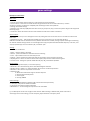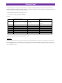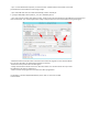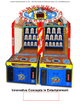
1
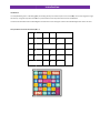
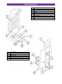
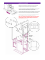
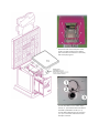
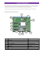
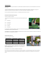
USER’S MANUAL
introduction
Introduction:
The LuckyNumbers game is a dexterity game, illuminating 32 lamps in a fixed sequence. Low value lamps are lit much longer than high
value lamps. The game stops when the button is pushed and wins the lamp value that was lit at that moment.
This document describes how to build the game and make the correct settings for various alternative configurations of the machine.
Lamp numbers and values for Field Layout = 1:
1
2
3
4
5
6
7
8
9
10
11
12
13
14
15
16
17
18
19
20
21
22
23
24
25
26
27
32
28
29
30
31
device description
1
2
3
4
5
6
7
8
9
10
1
2
3
4
5
6
7
Upper marquee
Ticket dispenser
Playfield/jackpot/marquee to PCB connectors
Coins cashbox
PCB/power supply/amplifier access
Base
Side marquee x2
Jackpot value display
Playfield
Credits display
Tickets holder x2
Speaker
START/STOP button
Tickets out x2
Coin acceptor
Bill acceptor
Bill cashbox
machine assembly
Slide the base on the lower part of the device, be sure to connect LED
backlight connectors. Mount the base using the supplied screws.
Install the top marquee with JACKPOT display applying it on the rear of the
unit, earlier thread the cables through the hole on the right side of the
machine. Screw the top marquee using the supplied screws.
Install the playing field by placing the mounting bracket in the rear wall hole.
Place two screws in the holes in triangular brackets (see picture below).
Place the two screws under the handle to level the playfield. Remember
about adding spacers between the playing field and the wall.
Note: it is very important to connect the displays to the right connector.
The LED displays will suffer irreparable damage if connected to the
playfield lights/lamp connector.
Place the threads in the lower part of the
panel in the holes located on the oblique
part of the device and attach it on the inside,
with accompanying nuts.
Connect flat cable to to the credits display
soccet ( no. 1) and attach switch with bulb to
the START / STOP button socket ( no. 2).
Connect black cable with four pin connector
( no. 3) to a connector located in the lower
back part of the unit.
electronic control board
The LuckyNumbers game is controlled by a printed circuit board mounted on a 35mm DIN-rail. In its DIN rail holder, the board
measures approx. 11x13cm. The basic system can be equipped with optional extension boards, such as a 3G mobile data
interface, an intruder/tilt alarm board and extra display driver boards. The power supply is 12V DC.
This manual explains how to connect the system, and how to make the correct settings for the machine to operate.
Connectors and functions of the electronic board:
1
2
12
3
11
10
9
8
5
7 6
nr
1
2
3
4
5
6
7
8
9
10
11
12
function
USB connector for service and firmware uploads
Micro SD card
power supply
Audio output
Coin selector
inter-machine RS485 bus
Ticket dispenser
Start/Stop buttons and lamps
Gamefield lamps
Credit display
Jackpot display
Expansion connector
4
type
USB type B
4 pole CombiCon 5,08 mm
stereo jack
10 pole flatcable
3 pole CombiCon 3,81mm
5 pole CombiCon 3,81mm
16 pole flatcable
14 pole flatcable
14 pole flatcable
14 pole flatcable
4 pole CombiCon contra 5,08 mm
Display outputs (10 and 11):
Each display connector can drive a LED display with a maximum of 6 digits. For the LuckyNumbers game, typically the displays
are:
Top:
Mid:
Jackpot:
Credits:
4 digits of 100mm high
2 digits of 23mm high
Note: it is very important to connect the displays to the right connector. The LED displays will suffer irreparable damage if
connected to the playfield lights/lamp connector.
Lamp panel output (9):
The lamp panel of the LuckyNumbers game consists of 36
lamps, preferably LED lamps of 12V 3 Watt max.
The lamps are connected in a 6x6 matrix. The circuit diagram of
the driver shows the connections:
• pins 1 to 6 are column drivers that switch the vertical lines to
12V.
• pins 7 to 14 are row drivers that switch the horizontal lines to
GND.
Column 1 / Row 1 is the top, leftmost lamp. Column 6 / Row 6
is the bottom, rightmost lamp.
Typically, dedicated lamp boards are installed that have the
matrix interconnections conveniently build-in.
If discrete lamps are to be used, small interconnection boards
are available that connect 4 lamps with 2 pole pin-headers.
Nine of these boards are required to connect the entire panel:
Start/Stop Connector (8):
Connect pushbutton switches with lamps to the flatcable as
follows:
The buttons switch to pin 1 (GND), while the common pin for
the lamps is pin 16 (12V). The lamps may be 5W at most.
If the Auto-start facility is enabled, the Start button is no
longer required since the game will start immediately when
credits are available.
The error lamp will be lit if the machine runs out of tickets.
The bonus and jackpot lamps will be lit when bonus games or
the jackpot has been won, during the time that tickets are
being dispensed.
pin
1
2
3
4
5
6
7
8
9
10
11
12
13
14
15
16
function
GND
Start button
Stop button
spare button 1
spare button 2
spare button 3
spare button 4
spare button 5
spare lamp 4
spare lamp 3
spare lamp 2
spare lamp 1
Error lamp
Stop lamp
Start lamp
12V
Ticket dispenser (7):
LuckyNumbers can drive 3 types of dispensers: the Benchmark Intelli-Dual ticket dispenser, the CLE-101 dispenser, and the Suzo
Cube hopper.
Tip: when changing the dispenser for another type, remove power, disconnect the dispenser, reapply power and go to the
settings menu to select the new type of dispenser. Then remove power again and apply power. Failure
to do so, may start the dispenser and make it run indefinitely until the board is restarted.
Benchmark Intelli-Dual dispenser (type =0):
Connect according to the picture:
Take good care of connecting the correct colors and the wire link between pins 1
and 5:
pin 1:
white (Run)
pin 2:
blue (notch)
pin 3:
black (GND)
pin 4:
red (12V)
pin 5:
white (Run)
Do not install the “prize motor pull down” jumper on the control board: this prevents the ticket dispenser from dispensing one or
more tickets each time the machine powers up.
If the dispenser runs out of tickets, LuckyNumbers will indicate the error after 5 seconds and wait for the operator to restock and
press the button on the dispenser to restart it.
CLE-101 dispenser (type =1):
Connect according to the picture:
LuckyNumbers X10
pin 1
pin 2
pin 3
pin 4
pin 5
Function / color
CLE-101
Sensor /green
GND / black
12V / red
Run / white
OUT
GND
12V
IN
Install the “prize motor pull down” jumper JP01 on the control board: this
prevents the ticket dispenser from dispensing one or more tickets each
time the machine powers up.
If the dispenser runs out of tickets, LuckyNumbers will indicate
the error after 5 seconds and wait for the operator to restock the dispenser. That will automatically restart it, but some tickets
may not be dispensed if extra pulses were detected during restocking. Press the button on the dispenser to issue a few extra
tickets.
Suzo-Happ cube hopper Mk II (type = 2):
Connect according to the picture:
Take good care of connecting the correct pins:
LuckyNumbers X10
pin 1
pin 2
pin 3
pin 4
pin 5
Function / color
Cube Hopper
Sensor /yellow
Pin 6
12V / red
Run / black
Pin 8
Pin 9
Install the “prize motor pull down” jumper JP01 on the control board : this prevents the hopper from dispensing one coin each
time the machine powers up.
If the hopper runs empty, it will stop after 5 seconds, and
automatically retry after 30 seconds. This will prevent the motor from overheating.
Entropy 2000CR dispenser (type = 3):
Connections and wire colors are the same as for IntelliTicket (type 0, see above). Also, do not install the “prize motor pull down”
jumper on the control board: this prevents the ticket dyspenser from dispensing one or more tickets each time the machine
powers up.
If the dispenser runs out of tickets, LuckyNumbers will indicate the error after 5 seconds and stop the motor. Since it cannot
detect when the tickets are refilled or unjammed, the operator has to press any of the menu buttons on the control board, or
press the START button on connector (8) to restart the dispenser.
Inter-machine RS485 bus (6):
not used in LuckyNumbers.
Coin selector (5):
The 10 pin flatcable connector is designed to connect to an EMP 8x0.00 coin selector. The flatcable carries the DC power supply
to the selector, and coin inputs 1 to 6.
Audio connector (4):
Sound effects are generated on-board from MP3 files on the micro-SDcard. This stereo jack connector supplies low level audio
signals that are acceptable for almost any PC speaker system with built-in amplifier. Choose a system with the appropriate
amount of output power.
Power supply and expansion connector (3 and 21):
The power supply connects to the electronic control board through a 4-pin connector.
Plus is at the top, GND at the bottom. The intermediate 2 pins are communication wires that link the optional extension boards to
the control board.
Please check the wiring carefully before switching on.
The DIN-rail mounted switch-mode power supply can deliver 12V DC 60W from any mains power (110-240V,
50 and 60Hz). It supplies the electronic control board, the LED displays (approximately 15W), the lamp panel, the lamps in the
switches, and the coin selector.
The board can also work at 24V DC, and will automatically adjust the duty cycle of the displays and lamp panel to keep them
working at 12V.
Note: the supply voltage is connected directly to the ticket dispenser and the lamps of the start/stop connector. When using a
24V DC supply, make sure these lamps and dispenser can work at this voltage.
USB connector (1):
For service purposes only.
Micro-SD card (2):
The micro-SD card contains audio sample files in MP3 format. There is one sound sample for
each prize, and then some for pause, play and active (flash). Preferably, the MP3’s should have a
sample rate of 144kbps to 192kbps, but other rates may also function. If any of these files is
missing at power-up, the display will show an error message.
Do NOT change the SD-card under power. Switch off first!
To access the micro-SD card, slide the silver cover approximately 1mm upwards until it hinges
open. Install the micro-SD card exactly into the slots, keep it depressed there, then close the
cover and slide it down.
The micro-SD card must be formatted as FAT32, the most common format for these cards.
FAT12, FAT16, NTFS, ExFAT and other formats are not supported. If necessary, reformat the disk
on a Windows PC with a micro-SD slot or USB-interface, and force the PC to use FAT32 or use a
special tool, e.g. from:
https://www.sdcard.org/downloads/formatter_4/
Cards with a capacity of 1 to 16GB (a.o. Lexar and Sandisk) have been successfully tested in the machine, and larger capacities
should work as well. Note however that there may be cards for sale that do not work in embedded systems. It is strongly advised
to first test a card before ordering a larger batch.
menu navigation
Display and menus:
The LCD display normally shows the status of the machine: With every start and
stop of the game, and with every coin inserted this screen is automatically
updated.
Credits:
Revenue:
Games:
Tickets:
Bonuses:
Jackpots:
number of games left.
total sum of money inserted (*).
total number of games played (*).
total number of tickets dispensed (*).
total number of free games won (*).
total number of time the jackpot has been won.
(*) These totals will be maintained after power-down, and can be reset in one of
the menus.
To access the menus, press the ► button.
How to navigate the menus and to edit:
The currently selected menu line is indicated with a ► marker. To enter that
menu, press ►, or press ▲ or▼ to choose one of the other options.
To return to the previous menu, press ◄.
With the cursor at a line that contains a value to edit, press ► to move to the
highest digit of that value, and press again to move to the right to access lower
digits.
Press ▲ or▼to change the value and, when satisfied, press ◄ as many times as
required to exit the value.
In this example, the cursor has first been moved vertically to the Tmax [ms] line,
and subsequently ► has been pushed twice, first to move the cursor to the
hundreds digit, and secondly to the tens. This digit is now high-lighted in inversevideo.
When pressing ▲ or▼ the value will change by 10 higher or lower.
game settings
Description of the menus:
Main menu:
1. volume: set the audio system volume in a range of 0 (silence) to 10 (maximum).
2. reset counters: in this menu the totals shown in the game view screen can be reset. Moreover, it contains
an option to perform a cold boot to completely clear all settings to their factory defaults.
3. settings: all machine settings.
4. statistics: a list of all lamps (LM) with their ticket count (TC), lamp time (ms), and how many times the game has stopped at
that lamp (stops).
5. Fw version: shows the firmware version of the software and the serial number of the board.
Reset counters:
1. Reset Counters: are you sure? Change the N into Y by editing and return to the main menu to see that all counters have
been reset.
2. Cold Boot? Pin code: .. Edit the PIN code to 6391 and return to the menu line. The value will change to
0000 when the PIN code was OK and the factory defaults will have been installed, erasing all previous settings and restarting
the machine. Default settings include non-rotated high value lamp panel, Benchmark IntelliTicket dispenser, auto-start, coins
of 0,50, 1,00 and 2,00, and one credit for 0,50, 5 credits for 2,00.
Settings:
This menu has 6 submenus:
1. game : machine settings, see below.
2. chance : speed and factors that determine chance of winning.
3. coins : opens submenu with coin value and price list.
4. jackpot : set the minimum and maximum values of the jackpot, and the increment per game.
5. mystery/bonus : set the min and max value of the mystery lamp and the number of bonus games.
6. remote access : settings for optional mobile data link (2G / 3G), scheduled for Q3-2014.
Game settings:
1. Layout : 1= high value layout, 0 = low value layout (*).
2. Rotate 90 : set to YES if the lamp panel is mounted 90 degrees clockwise.
3. Random Lamps : default = N = sequential lamps. Set to Yes for random lamp selection.
4. AutoStart : set to YES if no stop button is to be used.
5. Dispenser type :
0 = Benchmark IntelliTicket single or dual fast dispenser.
1 = CLE-101 slow ticket dispenser.
2 = Cube hopper.
3 = Entropy 2000CR
Chance settings:
1. Dext.Factor : speed difference between high and low value fields (see below).
2. T max [ms] : lamp time for lowest value field.
3. T min [ms] : lamp time for highest value field.
4. Modulate if <= : random change of lamp time for low value fields.
(*) The field layouts can be seen at page 3 of this manual. When selecting a different field, please make sure to
also change various other settings, such as the speed, jackpot maximum and mystery value.
difficulity level
The dexterity game has a variable time that a field is lit, with high value fields showing much shorter than low values.The
default values give a good average number of tickets, but may need to be adjusted, in particular when changing the field layout
and when the number of tickets is too high or too low.
The LuckyNumbers game uses the following formula:
T = Tmin + (Tmax - Tmin) / (1 + (tickets / DextFact))
Examples:
default high value layout
tickets
0
1
3
5
15
50
250
500
recommended for low value
layout:
DextFactor = 5 (default) Tmin = 10 DextFactor = 2 (harder) Tmin = DextFactor = 1
(default)
10 (default)
Tmin = 6
200
200
200
Tmax = 200 (default)
Tmax = 200 (default)
Tmax = 200
168
137
103
129
86
55
105
64
38
58
32
18
27
17
10
14
12
12
11
Adjust these values to achieve a good profit/pleasure ratio.
“Modulate”:
To make the game a bit harder to play, the lamp time can be modulated for low value lamps. This modulation adds a random
time, up to 100ms, to the low value lamps. This will prevent the user to adjust his timing merely to the rhythm of the lamps.
The setting “Modulate if <=:” in the chance menu is by default set to 15. This means that all lamps with a value of 15 or less will
have a modulated on-time.
game price settings
Coins / Coin value:
the money value of each output of the coin selector.
Coins / Price list:
The money to insert for a LuckyNumbers game uses a price list, that entices the player to insert higher sums of money to get
more games.
Insert for games
$ 0.50 for 1
$ 2.00 for 5
$ 0.00 for 0
$ 0.00 for 0
$ 0.00 for 0
Both the price and the number of games can be modified.
The software allows smaller coins to be added up. So, if the smallest coin is e.g. 20ct, 3 coins will give 1 credit, 5 coins will give
2 credits, and 10 coins give 5. The total amount inserted is added up until the STOP button is pushed. After that, the remainder
of the money is still available, but counting will start from this remaining value and not from the previously inserted total.
firmware update
Firmware updates:
To install new firmware on the C491903 board, the microcontroller must first be
erased. Apply power to the board, and carefully short-circuit the 2 square pads
just above the coin selector connector, for 1 second. Note: Take ESD precautions
when handling the board and erasing it.
Warning; the board will not function after erasing the
processor: do not short circuit these pins unless you have
the firmware and programming software at hand.
The Atmel SAM-BA bootloader program can be found at:
http://www.atmel.com/tools/atmelsam-bainsystemprogrammer.aspx
Install it first, it comes with an extensive user manual. Preferable use a Windows
7 or 8 computer with the SAMBA program, and ignore all the info about driver
installation.
In our experience, the best procedure is as follows:
- Disconnect the USB cable.
- Apply power to the board and short-circuit the erase pads, then power-cycle the board.
- Connect the USB cable between the board and the Windows computer.
- The device driver will install itself automatically, and be called “\USBserial\COMx”, but in some
occasions it may get a funny name, e.g. GPS COM5. That is usually not a problem.
- Start the Sam-ba program and try the COM port in the top selection box. Also, select the correct
processor type: at91sam7x256-ek :
- Tip 1: on some Windows 8 computers, the Connect button is hidden because the window is too small:
pull the bottom of the window to make it large enough.
- Tip 2: if the USB driver does not install automatically, locate it manually at:
C: \ program files (x86) \ Atmel \ Sam-ba_2.xx \ drv \ atm6124_CDC.inf
- Tip 3: if the program crashes after clicking Connect, the PC needs to be restarted because the USB driver is still active and
does not terminate. This usually happens when trying to program more than one board without closing the program.
- Samba will now start with the “Flash” tab active. Enter the file to program into the “Send File Name”
box, and press Send File. This will flash the software into the chip.
- Answer No to the question about Locked regions.
- Finally, click the Execute button next to the “Boot from Flash” box. This will instruct the chip to start
the application next time it is switched on.
- Close and restart the program after each board has been programmed.
The firmware is named LuckyNumbersXXX.bin, where “XXX” is the version number
of the firmware.
terms of warranty
Magic Play Sp. z o.o. warrants that the LUCKY NUMBERS will be free from defects in electronics (motherboard, amplifier,
power supply, ticket dispenser, jackpot and credits displays, LED lights, coin acceptor) for a period of two years from the date
of delivery.
Warranty terms do not cover parts not included above.
Should the product prove defective during the warranty period, Magic Play, at its option, shall:
1. Repair the defective part by means of telephone support or depot service at no charge for parts of labor.
2. Replace the defective part with a comparable product which may be new or refurbished.
Provided that
1. Magic Play is informed of the defect immediately after it occurred. The faulty part should be dispatched to Magic Play or its
authorized distributor as soon as possible.
2. Magic Play diagnoses the defects were not caused by improper use, neglect, unauthorized modifications, repair, setup or
testing.
3. Only parts recommended and approved by Magic Play are covered by Magic Play Terms of Warranty.
UNDER NO CIRCUMSTANCES SHALL MAGIC PLAY SP. Z O.O. BE HELD RESPONSIBLE FOR LOSES IN PROFIT, USAGE OR
ACCIDENTAL SERIOUS DAMAGE TO THE MACHINE!
BUYER______________________________________
DATE_______________________________________
SERIAL NUMBER______________________________
SELLER_____________________________________