1
Mitsubishi Electric Industrial Robots
CR750/700/500 series
RT ToolBox2 / RT ToolBox2 mini
User's Manual
(3D-11C-WINE/3D-12C-WINE)
BFP-A8618-Q
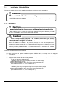
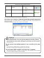
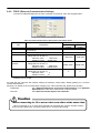
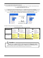
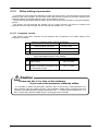
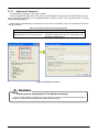
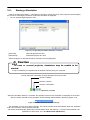
Safety Precautions
Before using the robot, always carefully read the
precautions below and the separate "Safety Manual" and
take all necessary safety measures.
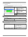
A. These show precautions based on Labor Health and Safety Regulations (Articles 36, 104, 150,
151).
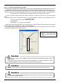
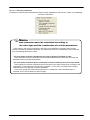
Caution
For the sake of safety, teaching work should only be performed by workers who have
received special education.
(The same is true for any maintenance work done with the power source not cut off.)
→Implementation of safety education
Caution
For teaching work, prepare work regulations concerning robot operation methods
and procedures, measures for when there is an abnormality and when restarting, etc.
Perform teaching work according to these regulations.
(The same is true for any maintenance work done with the power source not cut off.)
→Prepare work regulations.
Warning
Caution
For teaching work, set up a device that can stop operation immediately.
(The same is true for any maintenance work done with the power source not cut off.)
→Emergency stop switch setting
During teaching work, label the start switch etc. to indicate that teaching work is
underway.
(The same is true for any maintenance work done with the power source not cut off.)
→Display that teaching work is underway
Danger
In operation, prevent contact between workers and robots by preparing a fence and a
barrier.
→ Setting up a safety fence
Caution
Determine a uniform signal to relevant staff for the start of operation and use that
signal.
→ Signal for the start of operation
Caution
For maintenance work, in principle, cut off the power and label the start switch etc. to
indicate that maintenance work is underway.
→Display that maintenance work is underway
Caution
Before starting work, check the robot, emergency stop switches, related devices, etc.
and make sure there are no abnormalities.
→ Check before the start of work
B. This shows precaution points given in the separate "Safety Manual".
For details, please read the text of the "Safety Manual".
Caution
Use the robot in an environment that is within the range of its specifications. Failure
to do this can cause a drop in reliability and breakdown.
(Temperature, humidity, atmosphere, noise, etc.)
Caution
When transporting the robot, put it into its specified transport posture.
Failure to do this can cause a drop in reliability and breakdown.
Caution
Install the robot on a solid platform.
If the robot is in an unstable posture, this can cause positional deviation and
vibration.
Caution
Wire cables away from noise sources as much as possible.
If cables are brought too close to noise sources, this can cause positional deviation
and malfunction.
Caution
Do not apply excess force to a connector or bend a cable excessively.
Doing so can cause a contact defect or cut line.
Caution
Set work masses, including hands, so that they do not excess rated load or permitted
torque.
Exceeding either of these can cause an alarm or breakdown.
Warning
Install hands and tools and hold work securely.
Failure to do this can cause objects to fly loose during operation and cause personnel
injury or damage.
Warning
Caution
Ground the robot and controller reliably.
Failure to do this can cause malfunction due to noise or in an extreme case, electrical
shock.
Display the operating state while the robot is operating.
Lack of such a display can result in someone coming too close to the robot by mistake
or mistaken operation.
Warning
Always secure the priority right for control of the robot before doing any teaching work
within the robot's operating range. Failure to do this can allow the robot to start upon
instruction from the outside and cause personnel injury or damage.
Caution
Make the jog speed as slow as possible and do not take your eyes off the robot.
Failure to do this may cause a collision between a work piece and peripheral devices.
Caution
After completing program editing but before starting automatic operation, always
check operations with step operation. Failure to do this may cause a collision with a
peripheral device due to a programming mistake or the like.
Caution
Set up the safety fence in such a way that, while the equipment is running on
automatic, either the safety fence door is locked or if anyone tries to open the door,
the robot is stopped. Failure to take these protective measures can cause an accident
resulting in injury.
Caution
Never on your own judgment make an alterations or use maintenance parts other than
those designated. Doing so can cause breakdown and problems.
Warning
When moving the robot arm from the outside, never stick a hand or finger into an
opening. Depending on the posture, the hand or finger could get caught in the
equipment.
Caution
Do not switch the robot Off or make an emergency stop of the robot by switching Off
the robot controller's main power supply.
If the robot controller's main power supply is switched Off during automatic operation,
this can reduce the robot's precision. It could also cause the arm to fall or allow inertia
to result in collisions with peripheral device or the like.
Caution
When rewriting a program, parameters, or other internal information within the robot's
controller, do not switch Off the robot controller's main power supply.
If the robot controller's main power supply is switched Off during automatic operation
or while a program or parameter is being rewritten, there is a danger of the internal
information in the robot controller being destroyed.
Warning
For using RH-5AH/10AH/15AH series or RH-6SH/12SH/18SH series.
While pressing the brake releasing switch on the robot arm, beware of the arm which
may drop with its own weight.
Dropping of the hand could lead to a collision with the peripheral equipment or catch
the hands or fingers.
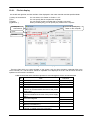
User's Manual Revision History
Printing Date
Manual No.
2008/04
BFP-A8618-*
2008/08
BFP-A8618-A
2008/10
BFP-A8618-B
2009/01
BFP-A8618-C
2009/06
BFP-A8618-D
2009/10
BFP-A8618-E
2010/04
BFP-A8618-F
2010/06
BFP-A8618-G
2010/10
BFP-A8618-H
2011/05
BFP-A8618-J
2011/07
BFP-A8618-K
2011/11
BFP-A8618-M
2012/05
BFP-A8618-N
2012/08
BFP-A8618-P
2013/02
BFP-A8618-Q
Revision Contents
First edition (Corresponds to the Ver.1.1)
Corresponds to the Ver.1.2 (Refer to the software revision history.)
Corresponds to the Ver.1.3 (Refer to the software revision history.)
Corresponds to the Ver.1.3.1
Corresponds to the Ver.1.4 (Refer to the software revision history.)
Corresponds to the Ver.1.5 (Refer to the software revision history.)
Corresponds to the Ver.1.6 (Refer to the software revision history.)
Corresponds to the Ver.1.6.1 (Refer to the software revision history.)
Corresponds to the Ver.1.7 (Refer to the software revision history.)
Corresponds to the Ver.1.8 (Refer to the software revision history.)
Corresponds to the Ver.2.00A (Refer to the software revision history.)
Corresponds to the Ver.2.10L (Refer to the software revision history.)
Corresponds to the Ver.2.20W (Refer to the software revision history.)
Corresponds to the Ver.2.30G (Refer to the software revision history.)
Corresponds to the Ver.2.40S (Refer to the software revision history.)
Software Revision History
Version
Release Date
1.0
2008/01
1.1
2008/04
1.2
2008/08
1.3
2008/10
1.4
2009/06
1.5
2009/10
1.6
2010/04
Revision Contents
Initial release (Japanese version only)
CRnQ Communications: Added the GOT transparent function.
Parameter editing: Added the Multiple CPU setting screen.
[Communication Setting]
- Changed the Initial value of USB, TCP/IP and RS-232 setting.
- Added the CRnQ communication routes when "Ethernet" is selected.
(Added the Ethernet port communications.)
[Program editor]
- Added “Comment Selection”/”Uncomment Selection” function.
- Added the function to edit the backed up program data.
[Project]
- Added the function to import the project.
[Parameter]
- Added the function to display the parameter changed from initial value.
[Restore]
- Added the function to restore individually data backed up by selecting
"All files".
etc.
[Operation of Project Tree]
- Added the function to copy the robot program by drag and drop.
[Operation of Workspace]
- Added the "Edit project" screen when the new workspace is made.
[Parameter]
- Added the function to print the parameter changed from initial value.
- Added the screen of setting the CC-Link parameter and PROFIBUS
parameter.
[Backup]
- Added the function to save data from all robot controllers by batch
processing.
etc.
[Parameter]
- Added the function to edit by offline.
[Program editor]
- Added the function to remove comments from all line in the program.
[Communication Setting]
- Added the screen of setting GOT communication.
[Parameter]
- Added the screen of editing the Work coordinate parameters.
[SQ Direct]
- Added the screen of editing the SQ Direct positions.
[Program editor]
- Added the function to check the program name when creating it by
offline.
- Added the function to rename the positional data.
- Changed an initial value of the position data to the present location.
- Added the function of jumping to the specified positional data.
- Added the function of searching the positional data.
- Added the function of distinguishing online editing and offline editing of
program by color.
[Simulation]
- Added the function of the Tool-JOG and Work-JOG on the simulation.
- Added the function of displaying the User defined area and the Free
Plane Limit in 3D viewer of simulation.
[Program Management]
- Added the function of changing the window size.
[Monitor]
- Added the function of stopping the program of all task-slots.
Version
1.6.1
Release Date
2010/06
1.7
2010/10
1.8
2011/05
2.00A
2011/07
2.10L
2011/11
2.20W
2012/05
2.30G
2012/08
Revision Contents
[Parameter]
- Added the function of editing the “Temp in RC” parameters.
[Communication Setting]
- Added the GOT(Ethernet) transparent mode.
[Simulation]
- Added the “3D Monitor” button to the screen of simulation operation.
- "3-axis XYZ" and "Cylinder" are added to JOG mord.
[Monitor]
- Added the function of error record.
[Computer syastem]
- Corresponded to Windows 7.
[Workspace]
- Added the function to change the name of the workspace.
[Servo monitor]
- Added the "ABS", "Speed", "Current", and "Power" of servo monitor.
[Operating Environment]
- Added the the Operating systems for which operation is warranted.
[Maintenance]
- Added the security function of the robot controller (Setup the password).
[Others]
- Changed the icon.
- Corresponded to iQ Works(MELSOFT Navigator).
etc.
[Simulator]
- A maximum of eight simulators can be started.
[Tool]
- Added the function “Force control log viewer”.
[Parameter]
- Added the “IO unit parameter”.
- Added buttons “Force initial setting”, “Force control mode”, “Force
control feature“, and “Force log setting”.
[Monitor]
- Added the IO unit monitor.
- Added the display of 3D monitor of several robots.
- Added the Encoder temp in the display of Load.
[Parameter]
- Added “Mode switch judgment/Speed reference” tab in “Force control
feature” screen.
- Changed “Electric hand teach” screen.
- Added “Electric hand table” screen.
[Maintenance]
- Added the function “Tool automatic calculation”.
- Added the File manager
[Communications Settings]
- Corresponded to CC-Link/IE
[Tool]
- Added the user definition screen editing function.
[Simulator]
- Added the function to manage the parts of layout by using a group..
- Added the reading function of 3D model parts.
- Added the function of designing a robot hand and of displaying it on "3D
view" screen.
etc.
[Parameter]
- Added buttons “Force initial setting”, “Force control mode”, “Force
control feature“, and “Force log setting”.
Version
2.40S
Release Date
2013/02
Revision Contents
[Parameter]
- Added the function of editing the “Collision avoidance area” parameters.
PREFACE
Thank you for purchasing this MELFA Mitsubishi Electric industrial robot.
This document is the user's manual for the MELSOFT "RT ToolBox2" and "RT ToolBox2 mini".
This document will help you to use the functions of this software to the maximum over a wide range of
stages, from initial robot start to program writing, editing, and management.
In order to operate the robot safely, carefully read this document and the safety manual that comes with the
robot main unit before operating the robot. Also, store this manual carefully so that you can take it out and
read it whenever needed.
Target versions for this document
This document is for the MELSOFT "RT ToolBox2" and "RT ToolBox2 mini" Version 2.40S and supports the
following robot controllers.
・ CRn-500 series controllers
・ CR750-Q/CRnQ-700 series controllers
・ CR750-D/CRnD-700 series controllers
In this manual, these also have the part written as “CR750/700/500 series”.
Target readers for this document
This document assumes that the reader understands basic Microsoft Windows operation methods and the
robot controller.
Those who have not mastered basic computer operation methods should read the user's manual for their
computer.
Notation method in this document
Danger
This indicates an item for which incorrect handling could present imminent danger
of death or injury.
Warning
This indicates an item for which incorrect handling could present a danger of
death or injury.
Caution
This indicates an item for which incorrect handling could present a danger of
impairment. It could also present a danger of just physical damage.
This document uses the following general terms and abbreviations
General Term/Abbreviation
Contents
RT ToolBox2
General name for the RT ToolBox2 and RT ToolBox2 mini
To distinguish them in explanations, these two are called the "standard
edition" and "mini edition".
Universal model QCPU
General term for Mitsubishi PLC CPU modules of Q02U, Q03UD,
Q03UDE, Q04UDH, Q04UDEH, Q06UDH, Q06UDEH, Q13UDH,
Q13UDEH, Q26UDH and Q26UDEH.
Built-in Ethernet port QCPU
General term for Mitsubishi PLC CPU modules of Q03UDE, Q04UDEH,
Q06UDEH, Q13UDEH and Q26UDEH.
GX Developer
Abbreviation of SW D5C-GPPW-E(-EV) / SW D5F-GPPW-E type of
Mitsubishi PLC programming software package.
The Microsoft® Windows® operating system is a registered trademark of the Microsoft Corp. of the United States in the United States
and other countries.
Adobe® and Acrobat® are registered trademarks of Adobe Systems Incorporated.
The system names, product names, etc. in this manual are generally trademarks and registered trademarks of their respective
TM
companies. In the main text, the ©, ®, and marks are omitted.
Transfer of all or part of the contents of this document without permission is prohibited.
The contents of this document are subject to change without notice.
Every effort has been made to ensure the accuracy of the contents of this document, but if you should notice any unclear point, mistake,
or omission, please notify Mitsubishi Electric.
Copyright(C)2008-2013 MITSUBISHI ELECTRIC CORPORATION
Contents
1.
Usage
1-18
1.1.
How to Use this Document ......................................................................................................... 1-18
1.2.
Checking the Product.................................................................................................................. 1-18
1.2.1.
Checking the package ......................................................................................................... 1-18
1.2.2.
Checking the CD-ROM contents ......................................................................................... 1-18
1.2.3.
About the "MelfaRXM.ocx" communications middleware ................................................... 1-18
1.3.
Items to be prepared by the customer ........................................................................................ 1-19
1.3.1.
Computer system ................................................................................................................ 1-19
1.3.2.
Computer cable ................................................................................................................... 1-19
1.4.
Operating Environment ............................................................................................................... 1-20
1.4.1.
Connectable robot controllers ............................................................................................. 1-20
1.4.2.
Computer system ................................................................................................................ 1-21
1.5.
Installation, Uninstallation ........................................................................................................... 1-22
1.5.1.
Installation ........................................................................................................................... 1-22
1.5.2.
Uninstall ............................................................................................................................... 1-26
1.5.3.
USB driver (CR750-D/CRnD-700 series robot controller) installation................................. 1-27
1.5.4.
CRnQ communications USB driver installation ................................................................... 1-28
1.5.5.
CRnQ Communications USB driver for GOT transparent function / GOT communitation
installation ........................................................................................................................................... 1-36
1.6.
When Starting at the Same Time as Another Product ................................................................ 1-38
1.7.
Upgrade of software.................................................................................................................... 1-38
2.
RT ToolBox2 Usage
2.1.
2.2.
2.3.
2.4.
3.
Starting RT ToolBox2................................................................................................................... 2-39
Explanation of RT ToolBox2 Screens.......................................................................................... 2-40
Communications Server 2........................................................................................................... 2-44
Closing RT ToolBox2................................................................................................................... 2-46
Notes of when RT ToolBox2 is used with iQ Works (MELSOFT Navigator)
3.1.
3.2.
3.3.
3.4.
2-39
3-47
Notes of when RT ToolBox2 is installed...................................................................................... 3-47
Notes concerning workspace operation...................................................................................... 3-47
Notes concerning Project operation............................................................................................ 3-48
Notes to edit the workspace created by iQ Works(MELSOFT Navigator) .................................. 3-49
4.
Basic Functions
4-50
5.
Workspaces and Projects
5-52
5.1.
5.2.
5.3.
5.4.
5.5.
5.6.
5.7.
5.8.
5.9.
5.10.
5.11.
5.12.
5.13.
5.14.
6.
Workspaces and Projects ........................................................................................................... 5-52
Creating a New Workspace ........................................................................................................ 5-54
Opening an Existing Workspace ................................................................................................. 5-55
Closing a Workspace .................................................................................................................. 5-55
Deleting a Workspace ................................................................................................................. 5-56
Saving a Workspace ................................................................................................................... 5-56
Changing a Workspace Name and Workspace Title .................................................................. 5-57
Adding a Project.......................................................................................................................... 5-59
Changing a Project Name........................................................................................................... 5-60
Deleting a Project........................................................................................................................ 5-61
Contents of Project Tree ............................................................................................................. 5-62
Copying Programs Between Projects ......................................................................................... 5-63
Import of project .......................................................................................................................... 5-64
Offline/Online/Simulation............................................................................................................. 5-66
Connecting with the Robot
6.1.
6.2.
6-68
Robots Connected and Types of Communication....................................................................... 6-68
Connection Settings .................................................................................................................... 6-70
6.2.1.
6.2.2.
6.2.3.
6.2.4.
6.2.5.
USB Communication Settings .............................................................................................6-71
TCP/IP (Ethernet) Communication Settings ........................................................................6-72
RS-232 Communication Settings.........................................................................................6-74
GOT Communications Settings ...........................................................................................6-75
CRnQ Communications Settings .........................................................................................6-76
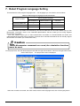
7.
Robot Program Language Setting
7-84
8.
Writing Programs
8-85
8.1.
Writing a New Program ...............................................................................................................8-86
8.1.1.
Writing a new program on the computer..............................................................................8-86
8.1.2.
Writing a new program in the robot controller......................................................................8-87
8.2.
Opening an Existing Program .....................................................................................................8-88
8.2.1.
Opening an existing program on the computer ...................................................................8-88
8.2.2.
Opening a program in a robot controller ..............................................................................8-88
8.2.3.
Read Items when opening program in robot controller........................................................8-89
8.2.4.
Opening a program in the backup data ...............................................................................8-90
8.3.
Explanation of Program Edit screen............................................................................................8-91
8.4.
Program Editing Menu Bar ..........................................................................................................8-92
8.5.
Customizing the Program Edit Screen ........................................................................................8-94
8.5.1.
Changing the display area ...................................................................................................8-94
8.5.2.
Command format hints.........................................................................................................8-95
8.5.3.
Character colors...................................................................................................................8-95
8.5.4.
Changing the font.................................................................................................................8-96
8.5.5.
Save and Read of program..................................................................................................8-96
8.5.6.
Get current position..............................................................................................................8-97
8.5.7.
Setting the background color of the program editor ............................................................8-97
8.6.
Program Editing...........................................................................................................................8-99
8.6.1.
MELFA-BASIC V command statement editing ....................................................................8-99
8.6.2.
MELFA-BASIC IV and Movemaster command command statement editing ....................8-100
8.6.3.
Position variable editing .....................................................................................................8-101
8.6.4.
Edit assist functions ...........................................................................................................8-103
8.7.
Saving Programs ....................................................................................................................... 8-113
8.7.1.
Save ................................................................................................................................... 8-113
8.7.2.
Saving on computer ........................................................................................................... 8-114
8.7.3.
Saving in robot controller ................................................................................................... 8-115
8.7.4.
Items written when saving in robot .................................................................................... 8-116
8.7.5.
Setting the syntax check for before program saving ......................................................... 8-118
8.8.
Program Printing........................................................................................................................ 8-119
8.8.1.
Checking a print image ...................................................................................................... 8-119
8.8.2.
Printing a program ............................................................................................................. 8-119
8.8.3.
Setting to print a program .................................................................................................. 8-119
8.9.
Program Debugging ..................................................................................................................8-120
8.9.1.
Starting debugging .............................................................................................................8-120
8.9.2.
Executing programs step by step ......................................................................................8-121
8.9.3.
Revising programs .............................................................................................................8-123
8.9.4.
Setting and deleting breakpoints .......................................................................................8-124
8.9.5.
Position jump .....................................................................................................................8-125
8.9.6.
Ending debugging ..............................................................................................................8-126
8.10. Program Management...............................................................................................................8-127
8.10.1. Program list display............................................................................................................8-128
8.10.2. Copy...................................................................................................................................8-129
8.10.3. Move ..................................................................................................................................8-130
8.10.4. Delete.................................................................................................................................8-131
8.10.5. Rename .............................................................................................................................8-132
8.10.6. Protect settings ..................................................................................................................8-132
8.10.7. Comparison........................................................................................................................8-133
8.11. Program Conversion..................................................................................................................8-134
8.11.1. Starting program conversion ..............................................................................................8-134
8.11.2. Line number conversion (from MELFA-BASIC IV to MELFA-BASIC V) ............................8-135
8.11.3. Position data conversion (from E/EN/M1/M2 series to CR750/700/500 series)................8-137
9.
Position data editing for SQ Direct
9-139
9.1.
Diffence from program editting.................................................................................................. 9-140
9.1.1.
Add/Edit position data........................................................................................................ 9-140
9.1.2.
Delete position data........................................................................................................... 9-140
9.1.3.
Editing supporting function ................................................................................................ 9-140
9.2.
Online editing ............................................................................................................................ 9-141
9.3.
Offline editing ............................................................................................................................ 9-142
9.3.1.
Creating the new SQ Direct file ......................................................................................... 9-142
9.4.
Program management .............................................................................................................. 9-143
9.4.1.
List of SQ Direct files indication......................................................................................... 9-144
10. Setting Parameters
10-146
10.1. Editing from parameter list ...................................................................................................... 10-147
10.1.1. Starting ............................................................................................................................ 10-147
10.1.2. Parameter editing ............................................................................................................ 10-149
10.1.3. Edit of parameter changed from initial value ................................................................... 10-150
10.1.4. Parameter list reading ..................................................................................................... 10-151
10.1.5. Finding parameters.......................................................................................................... 10-151
10.2. Robot Controller Operation Modes for Parameter Writing...................................................... 10-152
10.3. Operating Range Parameters ................................................................................................. 10-153
10.4. Jog Parameters....................................................................................................................... 10-154
10.5. Parameters of the Hand .......................................................................................................... 10-155
10.5.1. Hand parameters............................................................................................................. 10-155
10.6. Weight and Size Parameters .................................................................................................. 10-156
10.7. Tool Parameters ...................................................................................................................... 10-157
10.8. Slot Tables............................................................................................................................... 10-158
10.9. Output Signal Reset Pattern Parameters................................................................................ 10-159
10.10. Assigning Dedicated Input/Output Signals ............................................................................. 10-160
10.10.1. General 1 Parameters ..................................................................................................... 10-160
10.10.2. General 2 parameters...................................................................................................... 10-160
10.10.3. Data parameters.............................................................................................................. 10-161
10.10.4. Jog parameters................................................................................................................ 10-161
10.10.5. Hand parameters............................................................................................................. 10-162
10.10.6. Warm-up operation parameters....................................................................................... 10-162
10.10.7. Slot start (each slots) parameters.................................................................................... 10-163
10.10.8. Slot stop (each slots) parameters.................................................................................... 10-163
10.10.9. Servo On/Off (each robot) parameter.............................................................................. 10-164
10.10.10. Machine lock (each robot) parameters............................................................................ 10-164
10.11. RS-232 Setup Parameters...................................................................................................... 10-165
10.12. User-defined area Parameters................................................................................................ 10-165
10.13. Free Plane Limit Parameters .................................................................................................. 10-166
10.14. Escape Point Parameters ....................................................................................................... 10-166
10.15. Robot Program Language Parameters ................................................................................... 10-167
10.16. Additional Axis Parameters ..................................................................................................... 10-168
10.17. Collision Detection Parameters............................................................................................... 10-169
10.18. Warm-Up Operation Parameters ............................................................................................ 10-170
10.19. Movement Parameters............................................................................................................ 10-171
10.20. Program Parameters............................................................................................................... 10-172
10.21. User Error Parameters ............................................................................................................ 10-173
10.22. Ethernet Settings..................................................................................................................... 10-174
10.23. Multiple CPU Settings ............................................................................................................. 10-175
10.24. CC-Link parameters ................................................................................................................ 10-176
10.25. PROFIBUS parameters........................................................................................................... 10-177
10.26. IO unit parameters .................................................................................................................. 10-178
10.27. Work coordinate paramater..................................................................................................... 10-179
10.28. Force control parameters ........................................................................................................ 10-180
10.28.1. Force initial setting........................................................................................................... 10-180
10.28.2. Force control mode.......................................................................................................... 10-181
10.28.3. Force control feature ....................................................................................................... 10-182
10.28.4. Force log setting .............................................................................................................. 10-184
10.29. Collision avoidance parameters.............................................................................................. 10-185
10.29.1. Collision avoidance area ................................................................................................. 10-185
10.30. Parameter printing ...................................................................................................................10-187
10.31. Offline editing of parameters ...................................................................................................10-189
10.31.1. Compliant version ............................................................................................................10-189
10.31.2. Creating the new parameter file.......................................................................................10-190
10.31.3. Edit of parameter backed up............................................................................................10-191
10.31.4. Offline editing of parameter..............................................................................................10-192
10.31.5. Restoring the edited parameter to the robot controller ....................................................10-193
10.31.6. Deletion of parameter folder edited by offline ..................................................................10-195
11. Status Monitoring
11-196
11.1. Robot Operation Monitoring .................................................................................................... 11-197
11.1.1. Slot operation status ........................................................................................................ 11-197
11.1.2. Program monitoring ......................................................................................................... 11-198
11.1.3. Movement status.............................................................................................................. 11-201
11.1.4. Errors ............................................................................................................................... 11-202
11.1.5. 3D Monitor ....................................................................................................................... 11-207
11.2. Signal Monitoring..................................................................................................................... 11-208
11.2.1. General signal.................................................................................................................. 11-208
11.2.2. Named signals ................................................................................................................. 11-211
11.2.3. Stop signal ....................................................................................................................... 11-213
11.2.4. Register (CC-Link) ........................................................................................................... 11-214
11.2.5. IO unit monitor ................................................................................................................. 11-218
11.3. Production Condition Monitoring ............................................................................................. 11-219
11.3.1. Operation hours ............................................................................................................... 11-219
11.3.2. Production information ..................................................................................................... 11-219
12. Maintenance
12-220
12.1. Setting Origin Data ..................................................................................................................12-220
12.1.1. Origin data input technique ..............................................................................................12-222
12.1.2. Mechanical stopper technique .........................................................................................12-223
12.1.3. Tool technique..................................................................................................................12-223
12.1.4. ABS origin technique .......................................................................................................12-224
12.1.5. User Origin Technique .....................................................................................................12-224
12.1.6. Origin Parameter Backup ................................................................................................12-225
12.2. Initialization..............................................................................................................................12-226
12.2.1. Starting .............................................................................................................................12-226
12.2.2. Setting the time in the robot controller .............................................................................12-226
12.2.3. Deletion of all robot programs..........................................................................................12-227
12.2.4. Initializing the battery remaining time ..............................................................................12-228
12.2.5. Serial number...................................................................................................................12-228
12.3. Maintenance Forecasting ........................................................................................................12-229
12.3.1. Specifications ...................................................................................................................12-229
12.3.2. Starting .............................................................................................................................12-229
12.3.3. Forecasting ......................................................................................................................12-230
12.3.4. Settings ............................................................................................................................12-231
12.3.5. Reset screen....................................................................................................................12-233
12.3.6. Resetting maintenance forecast information with teaching box ......................................12-235
12.3.7. Others ..............................................................................................................................12-236
12.4. Position repair Function...........................................................................................................12-237
12.4.1. Specifications ...................................................................................................................12-238
12.4.2. Starting .............................................................................................................................12-238
12.4.3. Flow of operations............................................................................................................12-239
12.4.4. Introduction ......................................................................................................................12-240
12.4.5. Communications settings.................................................................................................12-240
12.4.6. Robot selection and parameter backup ...........................................................................12-241
12.4.7. Revision parameter generation procedure selection .......................................................12-242
12.4.8. Program selection ............................................................................................................12-243
12.4.9. Program reading and backing up.....................................................................................12-244
12.4.10. Tool setting check ............................................................................................................12-245
12.4.11. Revision parameter selection ..........................................................................................12-246
12.4.12. Reteaching work ..............................................................................................................12-252
12.4.13. Writing parameters...........................................................................................................12-255
12.4.14. Controller power supply Off, On ...................................................................................... 12-256
12.4.15. Exit................................................................................................................................... 12-257
12.4.16. Revision parameter editing.............................................................................................. 12-258
12.5. Tool automatic calculation....................................................................................................... 12-259
12.5.1. Specifications................................................................................................................... 12-259
12.5.2. Starting ............................................................................................................................ 12-259
12.5.3. Flow of operations ........................................................................................................... 12-261
12.6. Servo Monitor.......................................................................................................................... 12-263
12.6.1. Position (ABS) ................................................................................................................. 12-263
12.6.2. Speed .............................................................................................................................. 12-264
12.6.3. Current............................................................................................................................. 12-265
12.6.4. Load................................................................................................................................. 12-266
12.6.5. Power .............................................................................................................................. 12-267
12.7. Security function of the robot controller (Password Setup)..................................................... 12-268
12.7.1. Register the Password .................................................................................................... 12-270
12.7.2. Change the Password ..................................................................................................... 12-271
12.7.3. Delete the Password ....................................................................................................... 12-272
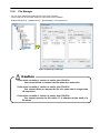
12.8. File Manager ........................................................................................................................... 12-273
12.8.1. File list display ................................................................................................................. 12-275
12.8.2. Copy ................................................................................................................................ 12-276
12.8.3. Delete .............................................................................................................................. 12-276
12.8.4. Rename ........................................................................................................................... 12-276
13. Option Card
13-277
14. Backup and Restore
14-278
14.1. Backup(Robot -> PC).............................................................................................................. 14-280
14.1.1. Saving data from one robot controller ............................................................................. 14-281
14.1.2. Saving data from all robot controllers(Online Project Backup)........................................ 14-283
14.2. Restore (PC -> Robot) ............................................................................................................ 14-285
14.3. Deleting Backup Data ............................................................................................................. 14-288
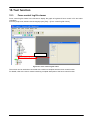
15. Tool function
15-289
15.1. Force control log file viewer .................................................................................................... 15-289
15.2. User definition screen ............................................................................................................. 15-290
15.2.1. Creating a new User definition screen file....................................................................... 15-291
15.2.2. Editing the page of user definition screen ....................................................................... 15-292
15.2.3. Edit of existing parts ........................................................................................................ 15-306
15.2.4. Copy/Paste of parts ......................................................................................................... 15-307
15.2.5. Movement of parts........................................................................................................... 15-308
15.2.6. Deletion of parts .............................................................................................................. 15-309
15.2.7. Change of page name ..................................................................................................... 15-309
15.2.8. Edit of ruled line............................................................................................................... 15-310
15.2.9. Deletion of user definition screen .................................................................................... 15-312
15.2.10. Import of the user definition screen ................................................................................. 15-314
15.2.11. Export of the user definition screen................................................................................. 15-316
16. Simulation
16-317
16.1. Starting a Simulation ............................................................................................................... 16-318
16.2. Explanation of the Simulation Operation Screen .................................................................... 16-319
16.3. Robot View (3D Monitor)......................................................................................................... 16-320
16.3.1. Robot View (3D View) Start ............................................................................................. 16-320
16.3.2. Displaying robots of more than one projects in 3D.......................................................... 16-321
16.3.3. The panel to change the perspective of robot view......................................................... 16-322
16.3.4. Robot display option ........................................................................................................ 16-323
16.3.5. Layout.............................................................................................................................. 16-328
16.3.6. Robot arrangement.......................................................................................................... 16-336
16.3.7. XYZ position variables..................................................................................................... 16-338
16.3.8. Hand ................................................................................................................................ 16-339
16.4. Robot Program Selection........................................................................................................ 16-341
16.5. Program Execution ..................................................................................................................16-342
16.6. Specifying the Starting Line for Program Execution ................................................................16-342
16.7. Breakpoint Setting ...................................................................................................................16-343
16.8. Step Operation.........................................................................................................................16-343
16.9. Direct Execution ......................................................................................................................16-344
16.10. Jog Operation ..........................................................................................................................16-345
16.11. Simulation Robot Position Variable Editing .............................................................................16-348
16.12. Tact Time Calculation ..............................................................................................................16-348
16.12.1. Conditions for tact time measurement .............................................................................16-349
16.12.2. Tact time measurement....................................................................................................16-350
16.12.3. Causes of tact time deviation...........................................................................................16-352
16.13. Ending Simulation....................................................................................................................16-353
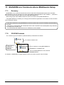
17. MelfaRXM.ocx Communications Middleware Setup
17.1.
17.2.
17.3.
17.4.
17-354
Summary .................................................................................................................................17-354
CD-ROM Contents ..................................................................................................................17-354
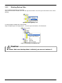
User's Manual Reading Guide.................................................................................................17-355
Installation................................................................................................................................17-355
18. Appendix
18-357
18.1. Q&A .........................................................................................................................................18-357
18.2. Index ........................................................................................................................................18-371
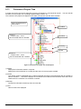
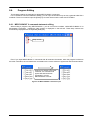
1. Usage
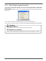
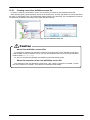
This explains precautions you need to know before using this software.
1.1.
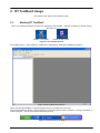
How to Use this Document
The manual is in the CR-ROM as the Adobe PDF file.
D:/Doc/BFP-A8618.pdf (Example for the CD-ROM drive is “D:”.)
For reading the manual, Adobe Acrobat Reader Ver.5.0 or more is required.
If Adobe Acrobat Reader isn’t installed, please download from following Adobe Systems Incorporated URL (As
of September, 2009)
URL: http://www.adobe.com/
1.2.
Checking the Product
1.2.1. Checking the package
Please check if all items shown below are included in the package.
- CD-ROM "RT ToolBox2"
- Setup Guide
- END-USER SOFTWARE LICENSE AGREEMENT
- License Certification
(Please make sure Product ID is printed on it.)
* Please contact the branch office or the agency if there is some shortage in the package.
1.2.2. Checking the CD-ROM contents
The CD-Rom has the following configuration.
/:
:
:
The files for installagion of this software
Doc ・・・・・・・ This manual (pdf)
Utility ・・・・・・・ The folder for setup of the communication middleware "MelfaRXM.ocx"
Sample ・・・・・ The sample data (Layout, Hand model)
1.2.3. About the "MelfaRXM.ocx" communications middleware
MelfaRXM.ocx is the ActiveX control that communicates to robot-controller. You can create the Windows
Application of "MELFA ROBOT" by using this control.
You can use "MelfaRXM.ocx" in only standard version of this software.
For information on how to set up "MelfaRXM.ocx", refer to "17 MelfaRXM.ocx Communications Middleware
Setup".
In case of using only the function of “RT ToolBox2”, you don't need to install this software.
1-18
1-18
1.3.
Items to be prepared by the customer
This explains what the customer needs to prepare in order to use this software
1.3.1. Computer system
Use a computer that meets the specifications given in: "1.4 Operating Environment".
1.3.2. Computer cable
Prepare the cable for connecting the controller and the computer. The cable required depends on the
connection specifications and controller used, as shown below.
For the RS-232 cable refer to the "Standard Specifications" for your robot.
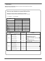
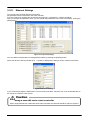
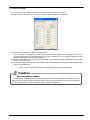
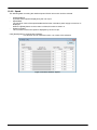
Table 1-1 CR750-D/CRnD-700/CRn500 Series Communication Cables
Method
USB
Ethernet
RS-232
Description
Model name
Manufacturer
USB A type, USB mini B type
10BASE-T, 100BASE-TX
CRnD-700
2D-232CBL03M
Mitsubishi Electric
series
RS-MAXY-CBL
For controller front panel
CRn-500
RS-AT-RCBL
Mitsubishi Electric
series
(for expansion serial
interface (option))
For expansion option box (CR1-EB3)
RS-AT-RCBL
Mitsubishi Electric
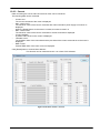
Table 1-2 CR750-Q/CRnQ-700 Series Communication Cables
Method
Description
Cables confirmed by Mitsubishi Electric to operate
properly
Model name
Manufacturer
ZUM-430
Loas Co.
USB-M53
Elecom Co.
Mitsubishi Electric System
GT09-C20USB-5P
Service
MR-J3USBCBL3M
Mitsubishi Electric
USB
USB A type to mini B type
Ethernet
10BASE-T, 100BASE-TX
For connecting by personal computer PLC CPU
QC30R2
(when Personal computer connector is
D-sub, 9-pin)
RS-232
Mitsubishi Electric
Caution
Use of USB to RS-232 does not guarantee normal operation.
When you use USB to RS-232 cable, normal operation is not guaranteed.
If you want to use RS-232 as a communication port, use of computer with serial ports is
recommended.
1-19
1-19
1.4.
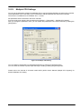
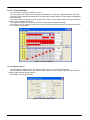
Operating Environment
This explains the operating environment.
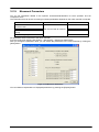
1.4.1. Connectable robot controllers
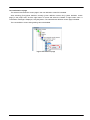
This software can be connected with the robot controllers shown below
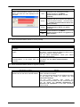
Table 1-3 Connectable Robot Controllers and Communications Types
Robot controller
CR750-D/CRnD-700
series
Communications (*1)
USB (*2)
(The photo is a robot
controller of CR3D-700.)
Remark
The commercial item such as computer and
cable might be unsuitable to compatibility with
our equipment or the FA environments of the
temperature and the noise, etc.
When it is used, please confirm the operation
enough, because you might have to take
measures against noise such as EMI measure
or addition of ferrite core.
Ethernet (TCP/IP)
RS-232
GOT communications
CR750-Q/CRnQ-700
series
Only CRnD-700 series
Communicate with CR750-D/CRnD-700series
controller connected with the GOT via Ethernet
by USB / RS-232.
GOT 1000 series and the Ethernet
communication unit (GT15-J1E71-100) are
needed. (*4)
USB (*2)
CRnQ
communications
(The photo is a robot
controller of CR3Q-700.)
Ethernet
(TCP/IP)
The PLC Ethernet interface module or Built-in
Ethernet port QCPU (*3) is required.
RS-232
CRn-500 series
Ethernet (TCP/IP)
The robot controller must have the "Ethernet
interface" option.
RS-232
(*1) The computer must have each ports for communications.
(*2) When using USB connection, 1 computer can connect to only 1 robot controller.
(*3) Built-in Ethernet port QCPU can be used with this software Ver.1.2 or later.
(*4) GOT communications can be used with this software Ver.1.5 or later.
This software can be connected to a maximum of 32 controllers at the same time. These controllers may be
different models.
1-20
1-20
1.4.2. Computer system
This software operates on PC/AT compatible computers that meet the following specifications.
Item
CPU
Main memory
Hard disk
Display
Optical device
Keyboard
Pointing device
Communications
functions
Communications port
OSs for which
operation is warranted
Recommended environment
Pentium III 1 GHz or higher
However, for using the simulation function, Pentinum IV 2 GHz or higher.
512 MB min.
Available capacity 300 MB min.
XGA (1024x768) or higher
CD-ROM drive
PC/AT compatible keyboard
Must operate on Windows
- USB2.0
(Caution: This cannot be used for connection with the CRn-500 series
controller.)
- LAN: 100Base-TX/10Base-T
- RS-232 communications port that operates on Windows (Minimum
9600bps: 1 port)
Must have one of the above interfaces
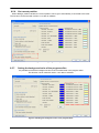
Windows 2000 Professional (32-bit version) (*2)
Windows XP Professional (32-bit version)
Windows XP Home Edition (32-bit version)
Windows Vista Ultimate (32-bit version)
Windows Vista Business (32-bit version)
Windows Vista Home Premium (32-bit version)
Windows Vista Home Basic (32-bit version)
Windows 7 Starter (32-bit version)
Windows 7 Home Premium (32/64-bit version) (*1)
Windows 7 Professional(32/64-bit version) (*1)
Windows 7 Enterprise (32/64-bit version) (*1)
Windows 7 Ultimate (32/64-bit version) (*1)
*1: Window 7 is corresponded with Version 1.7 or later of software. The 64-bit version of Windows
7 can be used with version 2.00A or later of this software.
*2 : When you use Windows 2000, it is necessary to install Service Pack4 and internet Explorer
version 5.5 or later.
1-21
1-21
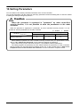
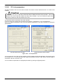
1.5.
Installation, Uninstallation
This section explains the method for installing the software and the method for uninstalling it.
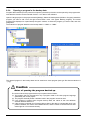
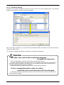
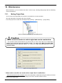
Caution
Uninstall RT ToolBox2 before installing.
If "RT ToolBox2" has already been installed in the personal computer, it is necessary to uninstall
it before "RT ToolBox2" is installed.
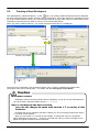
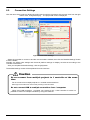
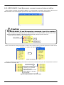
1.5.1. Installation
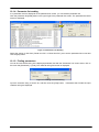
Caution
When installing, log in as a user with administrator authority.
When installing, log in as a user with administrator authority. The system will not let you install if
you log in as a user who does not have administrator authority.
Caution
Please input product ID attached to RT ToolBox2 again when you install a
standard version of RT ToolBox2 in the personal computer in which “iQ
Works(MELSOFT Navigator" is installed.
When RT ToolBox2 is installed in the personal computer in which “iQ Works(MELSOFT
Navigator)" is installed, product ID for “iQ Works(MELSOFT Navigator)” is displayed on "Input
Product ID" screen. RT ToolBox2 is installed in the personal computer as mini version when this
software is installed with this Product ID. Please input product ID attached to RT ToolBox2
product again when you install a standard version of RT ToolBox2.
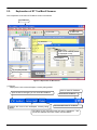
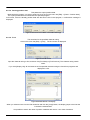
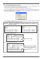
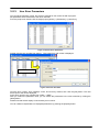
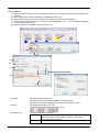
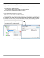
Install this software with the procedure below.
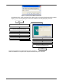
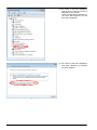
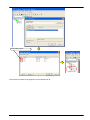
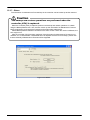
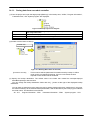
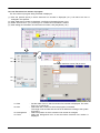
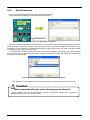
(1) When you insert this product into the computer's CD-ROM drive, the setup screen is displayed
automatically.
(2) If the setup screen is not displayed when you insert this product into the computer's CD-ROM drive,
display the setup screen with the following method.
- For any OS other than Windows Vista
- In Windows Vista, when using the [Start] menu with the classic display
1) Select [Start] button -> [Run].
2) Check the CD-ROM drive name, then input "drive name":\Setup.exe.
(If the CD-ROM drive is "D:", input "D:\Setup.exe".)
-
1-22
In Windows Vista, when not using the [Start] menu with the classic display
1) Click [Start] button -> [All Programs] -> [Accessories], then select [Run].
2) Check the CD-ROM drive name, then input "drive name":\Setup.exe.
(If the CD-ROM drive is "D:", input "D:\Setup.exe".)
1-22
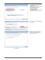
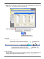
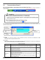
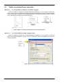
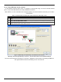
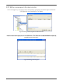
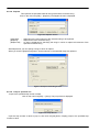
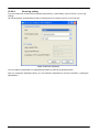
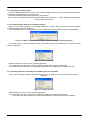
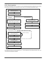
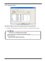
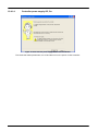
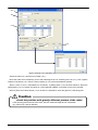
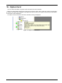
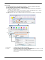
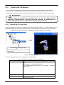
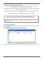
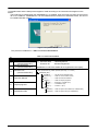
Figure 1-1 Specify the File Name and Execute
With Windows Vista, when using the classic display, when not using the [Start] menu with the classic
display, you can use the [Start] menu Search box instead of executing the [Run] command.
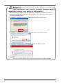
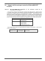
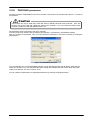
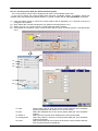
Start
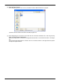
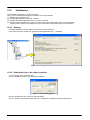
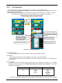
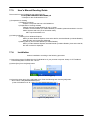
(a) Set the CD-ROM in PC's CD-ROM drive.
(f) Input Product ID
(b) Open "Setup.exe" in CD-ROM.
(when it is not started automatically)
(c) Starting installation Wizard
(d) License Agreement
(e) Input "Customer Information"
(g) Choose Destination Location
(h) Installation Wizard Complete
(i) Start the program, and confirm whether
the product was installed correctly
Finish
* Product ID is printed on the Certificate of License permission
* After the installation is completed, the computer should be likely to be rebooted.
1-23
1-23
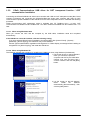
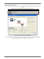
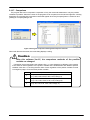
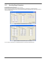
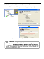
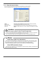
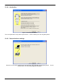
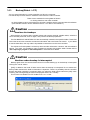
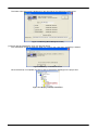
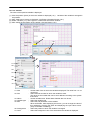
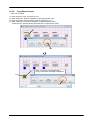
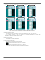
Caution
About the confirmation and warning message displayed during
installation (version 1.8 or earlier of this software)
During installation on Windows XP or Windows Vista, the following confirmation and warning
messages are displayed, but select to continue installation. If you select not to install, please
execute the installation again.
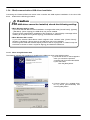
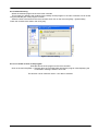
(1) Installation confirmation message for USB driver software (for Windows XP)
(2) Installation confirmation message for USB driver software (for Windows Vista)
(3) Installation warning message for USB driver software (for Windows Vista)
<Remark>
We have confirmed operation at our company. No problem occurs after installation.
1-24
1-24
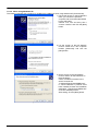
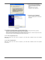
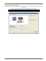
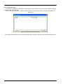
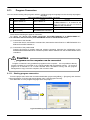
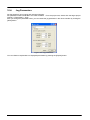
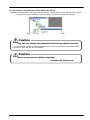
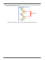
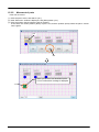
Caution
About the confirmation and warning message displayed during
installation (version 2.0 or later of this software)
During installation on Windows XP or Windows Vista, the following confirmation and warning
messages are displayed, but select to continue installation. If you select not to install, please
execute the installation again.
Installation confirmation message for USB driver software(ro Windows Vista)
When 「□ Always trust software from MITSUBISHI ELECTRIC CORPORATION」 is checked, the alert
message will not be displayed after next time.
1-25
1-25
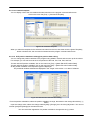
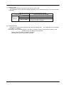
1.5.2. Uninstall
Uninstall with the following method.
Start uninstallation.
- For any OS other than Windows Vista
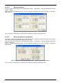
Execute [Start] – [Control Panel] [Program Add and Delete].
- Windows Vista
Open [Start] – [Control Panel].
When not using the classic display
With [Control Panel] [Program], execute [Uninstall Program].
From [Start] – [Control Panel], display the
control panel and select "Add/Remove
Programs".
Select the product to delete, then click the
"Change or Remove Programs".
For classic display
With [Control Panel] [Program Functions], select the
application name, then execute the uninstallation.
Completion
RT ToolBox2
Table 1-2 Uninstalling Applications (WindowsXP)
1-26
1-26
1.5.3. USB driver (CR750-D/CRnD-700 series robot controller) installation
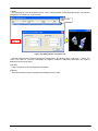
Connecting the CR750-D/CRnD-700 series robot controller with USB requires installation of the robot USB
driver. Install with the following procedure.
1.5.3.1. When using Windows 2000
When you connect the CR750-D/CRnD-700 robot controller and the computer with a USB cable, installation
starts and completes automatically.
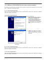
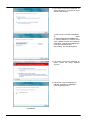
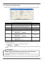
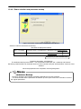
1.5.3.2. When Using Windows XP
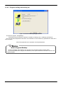
Below is the installation procedure for the USB driver using Windows XP (Professional).
1) When you connect the computer and
CR750-D/CRnD-700 series robot
controller with a USB cable, the
screen on the left is displayed. Select
"Install the software automatically
(Recommended)", then click the [Next]
button. Installation of the USB driver
starts.
↓
2) When the screen on the left is
displayed, the installation is complete.
Click the [Finish] button to end the
installation.
↓
(Completed)
1.5.3.3. When using Windows Vista
When you connect the CR750-D/CRnD-700 robot controller and the computer with a USB cable, installation
starts and completes automatically.
1.5.3.4. When using Windows 7
When you connect the CR750-D/CRnD-700 robot controller and the computer with a USB cable, installation
starts and completes automatically.
1-27
1-27
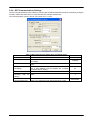
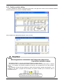
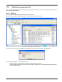
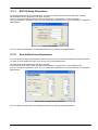
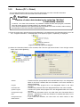
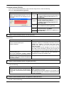
1.5.4. CRnQ communications USB driver installation
Connecting the CR750-Q/CRnQ-700 series robot controller with USB requires installation of the robot USB
driver. Install with the following procedure.
Caution
If the USB driver cannot be installed, check the following setting.
<When Windows 2000 is used>
If you have selected "Block-Prevent installation of unsigned files" after [Control Panel] - [System]
- [Hardware] - [Driver Signing], the USB driver may not be installed.
Choose "Ignore-Install all files, regardless of file signature" or "Warn-Display a message before
installing an unsigned file" for [Driver Signing], and install the USB driver.
<When Windows XP is used>
If you have selected "Block-Never install unsigned driver software" after [Control Panel] [System] - [Hardware] - [Driver Signing], the USB driver may not be installed.
Choose "Ignore-Install the software anyway and don't ask for my approval" or "Warn-Prompt me
each time to choose an action" for [Driver Signing], and install the USB driver.
1.5.4.1. When using Windows 2000
The following indicates the procedure for installing the USB driver when using Windows 2000.
1) The screen shown on the left appears
when you connect the personal
computer and Universal model QCPU
by the USB cable.
Click the [Next] button.
↓
2) Choose "Search for a suitable driver
for my device [recommended]" and
click the [Next] button.
↓
1-28
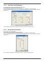
1-28
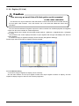
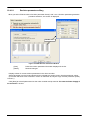
3) Check "Specify a location" and click
the [Next] button.
↓
4) As the left screen appears, set the
“C:\Melsec\EasySocket\USBDrivers”
and
If volume MELSOFT products have
been installed, browse the installation
destination “EasySocket\USBDrivers”
of the first installed product.
After setting, click the [OK] button.
↓
5) The screen on the left appears to
indicate completion of installation.
Click the [Finish] button.
↓
(Completed)
1-29
1-29
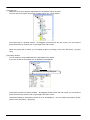
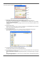
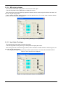
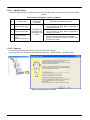
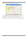
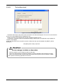
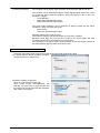
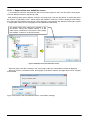
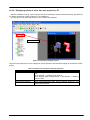
1.5.4.2. When using Windows XP
The following indicates the procedure for installing the USB driver when using Windows XP (Professional).
1) The screen shown on the left appears
when you connect the personal
computer and Universal model QCPU
by the USB cable.
Choose "Yes, now and every time I
connect a device" and click the [Next]
button.
↓
2) As the screen on the left appears,
choose "Install from a list or specific
location [Advanced]" and click the
[Next] button.
↓
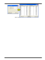
3) As the screen on the left appears,
choose "Search for the best driver in
these locations".
Check "Include this location in the
search" and set the
“C:\Melsec\EasySocket\USBDrivers”.
If volume MELSOFT products have
been installed, browse the installation
destination "EasySocket\USBDrivers"
of the first installed product.
After setting, click the [Next] button.
↓
1-30
1-30
4) As the screen on the left appears,
click the [Continue Anyway] button to
continue the installation of the USB
driver.
(No problem will occur after
installation of the USB driver.)
↓
5) The screen on the left appears to
indicate completion of installation.
Click the [Finish] button.
↓
(Completed)
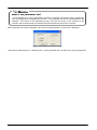
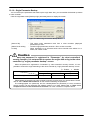
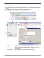
1.5.4.3. When using Windows Vista
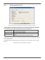
The following indicates the procedure for installing the USB driver when using Windows Vista (Business).
1) The screen shown on the left appears
when you connect the personal
computer and Universal model QCPU
by the USB cable.
Select "Locate and install driver
software (recommended)" and wait for
the search to end.
↓
1-31
1-31
2) The screen on the left is displayed, so
select "Browse my computer for driver
software (advanced)".
↓
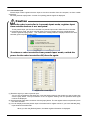
3) The screen on the left is displayed,
so
select
“C:\Melsec\EasySocket\USBDrivers”.
If volume MELSOFT products have
been installed, browse the installation
destination "EasySocket\USBDrivers"
of the first installed product.
After setting, click the [Next] button.
↓
4) The screen on the left is displayed, so
select "Install this driver software
anyway".
↓
5) The screen on the left appears to
indicate completion of installation.
Click the [Finish] button.
↓
(Completed)
1-32
1-32
1.5.4.4. When using Windows 7
The following indicates the procedure for installing the USB driver when using Windows 7.
1) When "Control panel" is selected
from the start menu with the USB
cable connected, the following
screens are displayed.
The screen on the left is displayed,
clicking the red circle part in this
screen.
↓
2) The screen on the left is displayed,
clicking the red circle part in this
screen.
↓
1-33
1-33
3) The screen on the left is displayed,
right-clicks on “Unknown device” is
displayed on this screen.
Select "Update Driver Software" of
the menu that right-clicks on this
item and is displayed.
↓
4) The screen on the left is displayed,
click lower "Browse my computer
for driver software".
↓
1-34
1-34
5) The screen on the left is displayed,
set "C:\Melsec\Easysocket
\USBdrivers".
If volume MELSOFT products have
been installed, browse the
installation destination
"EasySocket\USBDrivers" of the
first installed product.
After setting, click the "Next" button.
↓
6) The screen on the left is displayed,
click "install".
↓
7) The screen on the left appears to
indicate completion of installation.
Click the [Finish] button.
↓
(Completed)
1-35
1-35
1.5.5.
CRnQ Communications USB driver for GOT transparent function / GOT
communitation installation
Connecting the CR750-Q/CRnQ-700 series robot controller with USB via GOT transparent mode (Bus, Direct
coupled or Ethernet) and connecting the CR750-D/CRnD-700 series robot controller with USB via GOT
communication requires installation of the USB driver for the GOT transparent function. Install with the following
procedure.
CRnQ communication GOT transparent mode is available from RT ToolBox2 Ver.1.1 or later. GOT
communication is available from RT ToolBox2 Ver.1.5 or later. Ethernet is available from RT ToolBox2 Ver.1.7 or
later.
1.5.5.1. When using Windows 2000
When you connect the GOT and the computer by the USB cable, installation starts and completes
automatically.
If the USB driver cannot be installed, click the following setting.
If you have selected "Block-Prevent installation of unsigned files" after [Control Panel] - [System] [Hardware] - [Driver Signing], the USB driver may not be installed.
Choose "Ignore-Install all files, regardless of file signature" or "Warn-Display a message before installing an
unsigned file" for [Driver Signing], and install the USB driver.
1.5.5.2. When using Windows XP
The following indicates the procedure for installing the USB driver when using Windows (Professional)
1) The screen shown on the left appears
when you connect the personal
computer and GOT by the USB cable.
Choose "Yes, now and every time I
connect a device" and click the [Next]
button.
↓
2) As the screen on the left appears,
select
"Install
the
software
automatically (Recommended)", then
click the [Next] button.
↓
1-36
1-36
3) As the screen on the left appears,
click the [Continue Anyway] button to
continue the installation of the USB
driver.
(No problem will occur after
installation of the USB driver.)
↓
4) The screen on the left appears to
indicate completion of installation.
Click the [Finish] button to terminate
installation.
↓
(Completed)
If the USB driver cannot be installed, click the following setting.
If you have selected "Block-Never install unsigned driver software" after [Control Panel] - [System] [Hardware] - [Driver Signing], the USB driver may not be installed.
Choose "Ignore-Install the software anyway and don't ask for my approval" or "Warn-Prompt me each time
to choose an action" for [Driver Signing], and install the USB driver.
1.5.5.3. When using Windows Vista
When you connect the GOT and the computer by the USB cable, installation starts and completes
automatically.
1.5.5.4. When using Windows 7
When you connect the GOT and the computer by the USB cable, installation starts and completes
automatically.
1-37
1-37
1.6.
When Starting at the Same Time as Another Product
When starting this software and another one of our products at the same time, follow the following precaution.
Correct communications and screen display are sometimes not possible.
Table 1-4 Precautions for Starting at the Same Time with Another Product
Product name
RT ToolBox
computer support software
Explanation
Older version of this
software
MELFA-Works
3D robot simulator
MELFA-Vision
Network vision sensor
software
E/EN series computer support
software for Windows
E/EN series software
P/P-2
R-250R/R-300R series
software
1.7.
Precaution
Can not be used at the same time as
this software
MELFA-Works Ver.3.0 or lator can be
used at the same time as this
software.
Earlier version than Ver.3.0 can not be
used.
Start this software first.
Can not be used at the same time as
this software
Can be used at the same time as this
software
Upgrade of software
It is possible to download the latest version from site MELFANSweb where information on MITSUBISHI
ELECTRIC Corporation FA equipment product is offered. (It is only a Japanese site.)
http://wwwf2.mitsubishielectric.co.jp/melfansweb/robot/index.html
It is necessary to register to FA-LAND for downloading the software.
1-38
1-38
2. RT ToolBox2 Usage
This explains the usage of this software simply.
2.1.
Starting RT ToolBox2
When you install this software, a shortcut is prepared on the desktop. Start RT ToolBox2 by double clicking
this short cut.
Version 1.8 or earlier
Version 2.00A or later
Figure 2-1 RT ToolBox2 Shortcut
From [Start] button -> [All Programs] -> [MELSOFT Applications], select [RT ToolBox2] and start it.
Figure 2-2 RT ToolBox2 Initial Screen
When you start RT ToolBox2, "Communications Server 2" is started up as an icon.
This Communications Server 2 has functions for connecting with a robot controller or during a simulation, a
virtual controller. Do not close Communications Server 2.
Figure 2-3 Communication Server 2
2-39
2-39
2.2.
Explanation of RT ToolBox2 Screens
The composition of the main RT ToolBox2 screen is as follows.
(1) Title bar
(2) Menu bar
(4) Tool bar
(7) Screens
(5) Project tree
The screen currently active
is displayed on top.
(7)
(4) Screens
ツールバー
(6) Property window
(8) Status bar
Figure 2-4 Explanation of Main Screen
(1) Title bar
Displays the name of the workspace currently being edited.
Click to close RT ToolBox2.
After the size is changed, you can close RT ToolBox2.
Displays the name of the workspace currently being
edited.
Minimize RT ToolBox2.
Maximize/Minimize RT ToolBox2.
The status of the connection with the robot is displayed. The
connection statuses are online, offline, and simulation.
2-40
2-40
(2) Menu bar
Displays the names of the menus that can be used in RT ToolBox2.
When a menu is selected, a dropdown menu is displayed from which you can use various functions.
The menu bar display contents and their enabled/disabled status depend on which screen is currently
active.
(3) Dropdown menu
Displays the names of the functions you can use in RT ToolBox2.
When you click a function name, it displays a screen with the settings etc. for the selected function.
When " " is displayed at the right end of a dropdown menu, a dropdown menu for the selected function is
displayed
Click to display the screen.
Displays a
dropdown menu.
(4) Tool bar
Displays buttons for the functions assigned to the menu bar.
The tool bar display depends on which screen is currently active and on the robot connection status.
2-41
2-41
(5) Project tree
Displays a list of all the projects registered in the workspace and by functions.
From this tree, the program edit screen, monitor screen, etc. can be started.
The project tree is a docking window. By dragging the title section with the mouse, you can dock the
project tree at the top, bottom, left, or right edge of the main screen.
When the project tree is closed, you can display it again by clicking on the menu bar [View] -> [Project
Tree].
(6) Property window
You can reference various attributes of the workspace being edited.
If you click an item on the project tree, its attributes are displayed.
The attributes are being displayed.
The property window is a docking window. By dragging the title section with the mouse, you can dock the
project tree at the top, bottom, left, or right edge of the main screen.
The default setting for the property window is not to be displayed. You can display the property window
with the menu bar [View] -> [Property].
2-42
2-42
(7) Screens
Displays the screens that can be started from the project tree, including the program edit screen and
monitor screen. The currently active screen is displayed on top.
To close a screen, click the [ ] button in the upper-right corner of the screen.
You can also change the screen size with the button in the upper-right of the screen.
Minimize the screen.
Close the screen.
Maximize/Minimize the screen.
(8) Status bar
Displays RT ToolBox2 status information.
The status of the connection with the robot is displayed.
The connection statuses are online, offline, and simulation.
During program editing, displays the cursor position.
Displays the Num
Lock status.
Displays the Caps
Lock status.
(9) Handy menu display
By clicking the right button on the mouse, you can display the right button menu, depending on the work
contents. Using this menu can increase work efficiency.
During program editing, the right button menu includes such functions as [Copy], [Paste], and [Cut].
2-43
2-43
2.3.
Communications Server 2
When you start RT ToolBox2, "Communications Server 2" is started up as an icon.
This Communications Server 2 has functions for connecting with a robot controller or during a simulation, a
virtual controller.
Figure 2-5 Communications Server 2 as Icon
Caution
Do not close Communication Server 2 manually.
Communication Server 2 has functions for connecting to a robot controller or during simulation, a virtual
controller. Do not close Communication Server 2. Communication Server 2 closes automatically
when RT ToolBox2 is closed.
Turn Communication Server 2 into an icon.
Turn Communication Server 2 into an icon with the
button.
When you return Communications Server 2 from an icon to its original size, you can check the status of the
connection with the robot.
(1) Title bar
(2) Line State
(3) Communication
State
(5) Robot
Information
(4) Robot
controller
Figure 2-6
Communication Server2
(1) Title bar
(AA/BB) AA: shows the number of robot controllers with which connections are established and BB:
shows the number of projects switched online.
(2) Line State
The connection status of the communication line with the robot is displayed. The status color indicates the
status of the robot controller that is currently being selected.
Table 2-1 Line State
Status
Connecting
Content
Indicates that the connection with the robot has been established.
Indicates that a communication to verify connection is being made in the
case of RS-232 connection.
Connection wait
Indicates the wait status for communication port connection in the case of
TCP/IP and USB connection.
Displayed when the data reception enable signal cannot be detected
because a cable has been disconnected or the robot has not been started
in the case of RS-232 connection.
Connection
Displayed when the communication port cannot be opened in the case of
error
TCP/IP and USB connection.
In the case of USB connection, if the USB driver has not been installed, it
is also displayed in red.
2-44
Color
Light blue
or
Blue
Green
Red
2-44
Status
Communication
Setting error
Waiting
Content
Displayed when the communication port cannot be opened in the case of
RS-232 connection. This is not displayed in the case of TCP/IP
connection
Indicates the idling status displayed at the start of remote maintenance.
Color
Red
Yellow
(3) Communication State
The contents of communication with the robot controller are displayed.
(4) Robot
This changes the robot controller for which the "Line status" and "Communication status" are displayed.
This is only displayed for robot controllers that are online or have been switched to simulation status.
(5) Robot Information
Information on the currently connected robot can be referenced.
Figure 2-7 Connected Robot Information
Caution
Cautions when connected on USB with CRnQ communications
When connected on USB with CRnQ communications, after connecting normally, if the
communications are cut off due to any of the following external causes, the line status display
remains "Connected". If this happens, return this software offline, remove the cause of the cutoff,
and then go back online.
・ The robot controller power supply went off.
・ The communication cable was disconnected.
This software Ver.1.5 or later can communicate with robot controller by higher reliability communication. In this
case, line state color (connecting) of communication server 2 is “Blue”.
Table 2-2 Conbination of higher reliability communication
CRn-500
All versions
Robot controller software version
CR750-D/CRnD-700
CR750-Q/CRnQ-700
Ver.P7a or former Ver.P8 or later Ver.N7a or former Ver.N8 or later
Ver.1.4.1
This
or former
software
Ver.1.5
verion
or later
: Conventional communication (line state color (connecting) : light bule)
: Higher reliability communication (line state color (connecting) : blue)
2-45
2-45
Caution
Caution when connected on TCP/IP with higher reliability
communication
When connected on TCP/IP with higher reliability communication, connect only one line of one port
number.
If two or more lines are connected to the same port number, the communication error might occur.
2.4.
Closing RT ToolBox2
To close RT ToolBox2, on the menu bar, click [Workspace] -> [Close Application]. You can also close with the
[ ] button in the upper-right of the screen.
When you close RT ToolBox2, Communications Server 2 also closes automatically.
2-46
2-46
3. Notes of when RT ToolBox2 is used with iQ Works
(MELSOFT Navigator)
There are some limitations when robot controller's workspace is made by using iQ Works(MELSOFT
Navigator) or RT ToolBox2 is started from iQ Works(MELSOFT Navigator). Please refer to the following notes
when you use iQ Works(MELSOFT Navigator).
RT ToolBox2 corresponding to iQ Works(MELSOFT Navigator) is version 2.00A or later.
3.1.
Notes of when RT ToolBox2 is installed
Notes 1-1:
Please input product ID attached to the product again when you install a
standard version of RT ToolBox2 in the personal computer in which “iQ
Works(MELSOFT Navigator" is installed.
When RT ToolBox2 is installed in the personal computer in which “iQ Works(MELSOFT Navigator)" is
installed, product ID for “iQ Works(MELSOFT Navigator)” is displayed on "Input Product ID" screen. RT
ToolBox2 is installed in the personal computer as mini version when this software is installed with this
Product ID. Please input product ID attached to RT ToolBox2 product again when you install a standard
version of RT ToolBox2.
3.2.
Notes concerning workspace operation
Notes 2-1:
The workspace name and the workspace title cannot be changed.
When RT ToolBox2 is started from iQ Works(MELSOFT Navigator), the workspace name and the
workspace title cannot be changed. "Edit workspace" in the dropdown menu of the workspace name is
displayed in the gray and cannot be selected. (Refer to “Figure 3-1 Menu of [Workspace] and
Dropdown-menu of the Workspace”)
Notes 2-2:
Please close RT ToolBox2 once when you edit another workspace.
The another workspace cannot be opened after closing the editing workspace when RT ToolBox2 is
started from iQ Works (MELSOFT Navigator). [New] of the [Workspace] menu and [Open] are displayed
in the gray, and cannot be selected. (Refer to “Figure 3-1 Menu of [Workspace] and Dropdown-menu
of the Workspace”) When you edit another workspace, please exit RT ToolBox2 once and start RT
ToolBox2 specifying another workspace from iQ Works(MELSOFT Navigator).
Notes 2-3:
It is not possible to save as another name when the workspace is edited.
The editing workspace cannot be saved as another name when RT ToolBox2 is started from iQ Works
(MELSOFT Navigator). [Save As] in [Workspace] menu is displayed in the gray and cannot be selected.
Dropdown-menu of Workspace
(online)
Menu of [Workspace]
Figure 3-1 Menu of [Workspace] and Dropdown-menu of the Workspace
3-47
3-47
3.3.
Notes concerning Project operation
Notes 3-1:
It is not possible to delete,or and import a project.
When RT ToolBox2 is started from iQ Works(MELSOFT Navigator), it is not possible to add a new
project, import a project, or delete an existing project. [Add project] and [Import project] ( in the dropdown
menu by selecting a workspace name) and [Delete project] ( in the dropdown menu by selecting a project
name ) are display in the gray and cannot be selected.
Dropdown-menu of the
Workspace
(online)
Dropdown-menu of the
Project
Menu of [Workspace]
Figure 3-2 Menu of [Workspace] and Dropdown-menu of the Workspace
Notes 3-2:
It is not possible to change a project name.
When RT ToolBox2 is started from iQ Works(MELSOFT Navigator), it is not possible to chage the
project in the editing workspace. "Project name" in "Edit project" screen is displayed in the gray, and
cannot be selected.
Figure 3-3 Edit project
3-48
3-48
3.4.
Notes to edit the workspace created by iQ Works(MELSOFT
Navigator)
Notes 4-1:
Do not change the composition
Works(MELSOFT Navigator).
of
the
workspace
created
by
iQ
The composition (changing a workspace name, changing a title, adding a project, deleting a project
or changing a project name) of the workspace made with iQ Works(MELSOFT Navigator) cannot be
changed with RT ToolBox2 started from iQ Works(MELSOFT Navigator). These information can be
edited with RT ToolBox2 started directly by the start menu etc. However, it becomes impossible to take
the correspondence in iQ Works(MELSOFT Navigator) when these information is changed. Please do
not change the composition (changing a workspace name, changing a title, adding a project, deleting a
project or changing a project name) of workspace when editing them with RT ToolBox2 started directly.
Prohibited matter in RT ToolBox2 started directly
Workspace
・ Change the workspace name.
・ Change the title.
Project
・ Add a project
・ Import a project
・ Delete a project
・ Change the project name
The workspace name made with iQ Works (MELSOFT Navigator) is set as follows. Please note the
handling of this workspace.
Workspace name
3-49
RT Workspace
This is fixation.
3-49
4.
Basic Functions
The basic functions of this software are shown below.
Table 4-1 RT ToolBox2 Basic Functions
Function
Offline
Robot model
Program
SQ Direct
Parameter
Online
Robot model
Program
SQ Direct
Parameters
Parameter list
Parameter
settings by
function
Monitors
Operation
monitor
Signal monitor
Work monitor
Maintenance
Home position
data
Initialization
Maintenance
forecast
Position repair
Tool
automatic
calculation
Servo monitor
Password Setup
File Manager
4-50
Explanation
Targets files on the computer.
Displays the model of the robot used.
Displays the names of the robot programs written on the computer.
Displays the SQ Direct files written on the computer. (*2)
It is possible to set the parameters by offline and save them to the files.
(*1)
The saved files can be sent to the robot controllers.
These are used with the robot controller connected.
Displays the model of the robot connected to the robot controller.
Displays the names of the programs stored on the robot controller.
It is possible to edit SQ Direct variables in the robot controllers. (*2)
It is possible to set the parameters and preserve them to the file without
connecting the robot controller. (*1)
And, the preserved parameter file can be forwarded to the robot controller.
The parameters can be set individually.
The parameters can be set by robot function individually.
The functions are as follows.
・ Operating range
・ Evacuation point
・ Jog
・ Robot language
・ Hand
・ Added axes
・ Weight and size
・ Collision detection
・ Tool
・ Heater operation
・ Slot table
・ Operation parameters
・ Output signal reset pattern
・ Program parameters
・ Dedicated input/output signal ・ User error
allocation
・ Ethernet setting
・ RS-232 settings
・ CC-Link parameter setting
・ User-defined area
・ PROFIBUS setting
・ Free plane limit
・ IO unit (*4)
・ Work coordinate (*2)
・ Force control (*4)
You can reference the slot status, program, monitor, operation status, and
current errors.
You can check the statuses of signals input to the robot and signals output
from the robot.
You can check the robot work time and production information for each
robot program.
This sets the robot home position.
This sets the robot controller's internal time, deletes all the programs in the
controller, initializes the battery time remaining, and sets the serial number
for the connected robot.
Forecasts the time for maintenance.
Supports recovery from home position deviation
The tool length is calculated automatically and the value of a tool parameter is set
up. (*5)
Monitors servo system information.
The password to limit controller's right of access is registered, changed or
deleted. (*3)
You can copy, delete and rename the file in the robot controller. (*5)
4-50
Function
Option card
Explanation
You can check information on option cards mounted in the robot controller.
Tool
Force
control
log
viewer
User definition screen
This function can display the graph of log data of force control in PC and
robot controllers.
It is possible to edit the user definition screen which can be operated by
highly efficient T/B. (*5)
Simulation
This can be used connected with a virtual robot.
*This can only be used with the standard edition.
Same functions as
The same functions can be used with a virtual robot controller as with an
online
online one.
Tact time measurement The tact time for the robot program with the specified contents can be
measured in the simulation.
Backup, restore
You can back up the information in the robot controller and restore backed
up information into the controller.
(*1) This function can be used with Version 1.4 or later of this software.
(*2) This function can be used with Version 1.5 or later of this software.
(*3) This function can be used with Version 2.00A or later of this software.
(*4) This function can be used with Version.2.10L or later of this software.
(*5) This function can be used with Version 2.20W or later of this software.
4-51
4-51
5. Workspaces and Projects
This explains about workspaces and projects.
5.1.
Workspaces and Projects
This software has workspaces and projects.
The information for one controller is managed as one project. A workspace can manage up to 32 projects. If
Ethernet is used for communications, you can simultaneously reference information on multiple projects (robot
controllers) registered in the workspace.
When using multiple robot controllers, it is convenient to manage with separate workspaces for each
manufacturing line and installation location.
(1) Using multiple robot controllers (up to 32)
RT ToolBox2
Workspace
Project
1
Project
2
Communication
Communication
Project
32
・・・
Communication
You can reference
the information for
multiple controllers
at the same time.
You can connect multiple
controllers at the same time.
...
Figure 5-1 Using Multiple Robot Controllers
(2) Using 1 robot controller
RT ToolBox2
Workspace
Project
1
Communication
Figure 5-2 Using One Robot Controller
Caution
You cannot edit multiple workspaces at the same time.
With this software, you cannot edit multiple workspaces at the same time. Register into a
single workspace all the projects (controllers) you want to reference at the same time.
Simultaneous connection with 32 units
The maximum of 32 robot connections is a theoretical value. It does not guarantee that if you
actually connect 32 robots, you will achieve the same performance as when only 1 robot is
connected. For example, if you monitor all the robots when 32 are connected, status updating is
slower than for when 1 robot is connected.
5-52
5-52
Workspace editing and storage and project addition etc. are explained from the next section on.
Caution
Update workspaces and projects offline.
In the online status or while a simulation is running, you can not perform the following
operations. Switch offline, then perform the operations.
・ Opening an existing workspace
・ Saving the workspace with a different name
・ Adding a project
・ Changing a project name
・ Deleting a project
For details on switching offline, see "5.14 Offline/Online/Simulation".
5-53
5-53
5.2.
Creating a New Workspace
Click [Workspace] -> [New Workspace] or click
(Ctrl + N). Creating a New Workspace screen is displayed.
Input the workspace name and title, and then click the [OK] button. The project edit screen is displayed, so set
the project name (arbitrary name), the communication method and the robot model for offline (both are the
information of the robot that you want to connect.), then click the [OK] button.
When you use the software Version 1.2 or earlier, the project edit screen is not displayed.
Version 1.3
or later
Version 1.2 or earlier
Figure 5-3 Creating a New Workspace
The project tree is displayed in the workspace and the "RC1" project is created as the default value.
This project name can be change later. For details, see "5.9 Changing a Project Name".
Caution
Workspace names
Workspace names are used as folder names in Windows, so you can not use characters that
can not be used in Windows folders names ( \ / : * ? “ < > | ).
Once a workspace has been created,
you can not change its name with version 1.7 or earlier of this
software.
Be aware that once a workspace has been created, you can not change its name with version
1.7 or earlier of this software.
When you use version 1.7 or earlier of this software, to change the name of a workspace,
select "Workspace"on the menu → "Save As", save with the name you want to change to, then
delete the original workspace with the old name.
5-54
5-54
5.3.
Opening an Existing Workspace
To open an already existing workspace, click [Workspace] -> [Open] or click
the workspace to edit, click the [OK] button.
(Ctrl + O). After selecting
Figure 5-4 Opening a Workspace
The names of the last up to four workspaces used are added to [Workspace] on the menu bar. You can open
one of these workspaces by clicking its name here.
The recently used
workspaces are added.
When you click one of these
workspace names, the
workspace is opened.
Figure 5-5 Recently Used Workspace Names
5.4.
Closing a Workspace
To close the workspace being edited, click [Workspace] -> [Close]. Note that to delete a workspce, you must
close it first.
5-55
5-55
5.5.
Deleting a Workspace
Click [Workspace] -> [Delete]. The "Delete Workspace" screen is displayed, so check the name of the
workspace to delete, and then click the [OK] button.
Figure 5-6 Deleting a Workspace
Caution
Deleting a workspace
To delete a workspace, close that workspace. You can not delete a workspace that is being
edited.
5.6.
Saving a Workspace
The information added to the workspace is saved automatically.
You can also save a workspace with a different name. Click [Workspace] -> [Save As], input the new
workspace name and title, then click the [OK] button.
Figure 5-7 Save As
5-56
5-56
5.7.
Changing a Workspace Name and Workspace Title
It is possible to change directly the workspace with version 1.8 or later of this software.
Caution
Don’t change the workspace name and the workspace title
made with iQ Works(MELSOFT Navigator).
Don’t change the workspace name and the workspace title made with iQ Works(MELSOFT
Navigator). It becomes impossible to take the correspondence in iQ Works(MELSOFT Navigator) when
these information is changed.
Click the name of the workspace with the right button on the mouse, then click "Edit workspace" on the right
button menu. The “Change Workspace” screen is displayed, so input the new workspace name and new
workspace title, then click the [OK] button.
Figure 5-8 Changing the name of the workspace and workspace title
Once a workspace has been created, you can not directly change its name with version 1.7 or earlier of this
software. When you use this software of these version, to change a workspace name, use the menu bar
[Workspace] -> [Save As] to save the workspace with the desired new name, then delete the old workspace.
When the workspace title is changed, click the name of the workspace with the right button on the mouse,
then click "Edit workspace title" on the right button menu. The workspace title screen is displayed, so input the
new workspace title, and then click the [OK] button.
5-57
5-57
Figure 5-9 Changing the title of the workspace (version 1.7 or earlier)
5-58
5-58
5.8.
Adding a Project
You can create up to 32 projects in one workspace.
Click [Workspace] -> [Add Project].
Figure 5-10 Adding a Project
After setting the project name, information on the robot connected, and the communication method, then click
the [OK] button.
The project is added to the workspace.
Projects can also be added from a project tree.
After selecting the workspace, use the mouse right button to select [Add project]. Or, double click the workspace
name on the project tree. (Note that this function can be used with Version 1.3 or later of this software)
Figure 5-11 Adding a Project from a Project Tree
Caution
Add a new projects offline.
It is possible to add a new project offline. A new project cannot be added, when the status of either of
project is "Online" or "Simulation".
Don’t add a project to the workspace made with iQ Works(MELSOFT Navigator).
Don’t add a project to the workspace made with iQ Works(MELSOFT Navigator). It becomes impossible
to take the correspondence in iQ Works(MELSOFT Navigator) when these information is changed.
5-59
5-59
5.9.
Changing a Project Name
You can change the name of a project even after it has been created.
Click the name of the project with the right button on the mouse, then click "Edit Project" on the right button
menu. The project edit screen is displayed, so input the new workspace title, then click the [OK] button.
Figure 5-12 Changing a Project Name
Caution
Don’t change a project name in the workspace
made with iQ Works(MELSOFT Navigator).
Don’t change a project name in the workspace made with iQ Works(MELSOFT Navigator). It becomes
impossible to take the correspondence in iQ Works(MELSOFT Navigator) when these information is
changed.
5-60
5-60
5.10.
Deleting a Project
A project can not be deleted when it is running a simulation or has a robot connected online.
Click the name of the project with the right button on the mouse, then click "Delete Project" on the right button
menu. The deletion confirmation message is displayed, so check that you have clicked the correct project
name, then click the [OK] button.
Figure 5-13 Deleting a Project
Caution
Don’t delete a project in the workspace
made with iQ Works(MELSOFT Navigator).
Don’t delete a project in the workspace made with iQ Works(MELSOFT Navigator). It becomes
impossible to take the correspondence in iQ Works(MELSOFT Navigator) when these information is
changed.
5-61
5-61
5.11.
Contents of Project Tree
A project tree shows the current workspace's project configuration in a hierarchical manner. You can start all
functions from the project tree, including program editing, monitor, etc.
The contents of the project tree depend on the state of connection with the robot controller.
Items are displayed for
each project.
(1) Offline
Project 1
<Project name: RC1>
Be connected with the controller.
(2) Online
(3) Backup
(4) Tool
Project 2
<Project name: RC2>
Not connected with the controller.
Figure 5-14 Structure of Project Tree in Workspace
(1) Offline
Displays the information stored in computer.
Displays the robot model set up currently and the name of robot programs created.
(2) Online
The "Online" section is displayed when a robot is switched into being connected online with its controller or
starts a simulation. This section displays the connected robot model and the information items that can be
referenced in the controller or a simulation controller.
(3) Backup
Controls the information backed up from the controller.
(4) Tool
Other functions are displayed.
5-62
5-62
Memo
It is possible to change the order of the display
of the project in the tree.
It is possible to change the order of the display of the project in the tree with version 1.3 or later.
Drag the project with the mouse, and drop it to the transportation destination. The project is
moved to the upper part of the dropped project.
Drag and drop
5.12.
Copying Programs Between Projects
To copy or move a created robot program to another project, do this with program management. For details on
the operation methods, see "8.10 Program Management", "8.10.2 Copy", or "8.10.3 Move".
With this software Version 1.3 or later, It is possible to copy by drag and drop the project name on the project
tree.
Please refer to "8.10 Program Management" in this manual for details.
5-63
5-63
5.13.
Import of project
It is possible that the project in other workspace is imported to the current workspace. Note that this function can
be used with Version 1.2 or later of this software.
The project can be imported only at offline. Please operate after change to offline when current mode is online
or simulation.
Caution
Don’t import a project to the workspace
made with iQ Works(MELSOFT Navigator).
Don’t import a project to the workspace made with iQ Works(MELSOFT Navigator). It becomes
impossible to take the correspondence in iQ Works(MELSOFT Navigator) when these information is
changed.
Click [Work space]->[Import project] on the menu bar.
After "Select Workspace" window is displayed, select the workspace including the project that you want to
import, and click [OK] button. The list of the project in selected workspace is displayed on "Select the projects"
window. Check the project, and click [OK] button.
5-64
5-64
Check the project.
Figure 5-15 Import of project
The maximum number of the projects in one workspace is 32.
5-65
5-65
5.14.
Offline/Online/Simulation
The project status are offline, online, and simulation. The meaning of each status and the contents displayed
in the project tree are shown below.
Table 5-1 RT ToolBox2 Status
Status
Offline
Explanation
Targets files stored on the computer.
When a robot is offline, the icon displayed on the left of
the project name on the project tree turns green and
Offline and Backup are displayed on the project tree.
Online
The robot is connected to the robot controller and you can
check and change the information in the controller
When a robot is online, the icon displayed on the left of
the project name on the project tree turns blue and
Offline, Online, and Backup are displayed on the project
tree.
This targets a virtual robot controller running on the
computer and you can check and change the information
in the virtual controller
When a simulation is running, the icon displayed on the
left of the project name on the project tree turns blue and
Offline, Online, and Backup are displayed on the project
tree.
Simulation
*This can only be
used with the
standard edition.
Project tree display
When this software starts, it goes into "Offline" status.
You can change a workspace or a project only in the "Offline" status.
Caution
The simulation function only supports the "RT ToolBox2" standard edition. It can not be used with the
mini edition.
Also, please be aware that even with the standard edition, the simulation function can not be used when
Movemaster commands are selected.
To switch among offline, online, and simulation, do so from [Online] on the menu bar or from the tool bar. With
the tool bar, you can switch as follows.
Switch to "Offline".
Switch to "Online".
Switch to "Simulation".
Figure 5-16 Explanation of Tool Bar
The current status and the statuses into which the current status can be switched are as followed.
5-66
5-66
Table 5-2 Current Status and Switchable Status
Current status
Offline
Switchable status
Can be switched to online or
simulation.
Online
Can only be switched to offline.
Simulation
Can only be switched to offline.
Menu bar [Online] display
Tool bar display
The current status is displayed checked at [Online] on the menu bar.
When switching to online or simulation, if multiple projects are registered in the workspace being edited, the
project selection screen is displayed as in "Figure 5-17 Screen for Selecting Project to Switch Online".
Check only the project to be switched online or to simulation, then click [OK]. Only one project can be
switched to simulation.
This screen is not displayed if there is just one project in the workspace.
Figure 5-17 Screen for Selecting Project to Switch Online
Caution
When using Ethernet, do not set an unconnected controller "Online".
When using Ethernet, if you try to switch "Online" a robot controller that is not connected, incessant
retries are made, which slows execution. Set "Offline" a robot controller that is not connected or
whose power is Off.
Do not connect from multiple projects to one controller at the same
time.
Do not connect from multiple projects to 1 controller at the same time.
Data might not be able to be read correctly referring to the same data.
Do not connect USB to multiple controllers from 1 computer.
When using USB connection, 1 computer can connect to only 1 robot controller. It is also not possible
to connect to multiple controllers by using the USB hub.
5-67
5-67
6. Connecting with the Robot
This explains the method for connecting the robot controller and the computer.
With this software, you must make the communication settings for each project.
Caution
Please do not pull out the cable while communicating.
Please never pull out the cable while communicating with the robot controller. If the communication
cable is removed while communicating, the status of the robot controller or the computer might
become abnormal. Please remove the cable when the status is not “Online” or this software exited.
Also when communicating by using the USB, please do not pull out
the USB cable until the communication is completed.
6.1.
Robots Connected and Types of Communication
When connecting the robot controller and computer, there are the methods shown below. Be aware that the
connection method that can be used is restricted by the robot controller connected.
Table 6-1 Robot Controllers That Can Be Connected and Types of Communication
Robot Controller
CR750-D/CRnD-700
series
Communication Type
USB (*4)
(The photo is a robot
controller of CR3D-700.)
Ethernet(TCP/IP) (*1)
RS-232
GOT communications
CR750-Q/CRnQ-700
series
Remarks
The commercial item such as computer and cable
might be unsuitable to compatibility with our
equipment or the FA environments of the
temperature and the noise, etc.
When it is used, please confirm the operation
enough, because you might have to take measures
against noise such as EMI measure or addition of
ferrite core.
Only CRnD-700
Communicate with CR750-D/CRnD-700 series
controller connected with the GOT via Ethernet by
USB / RS-232.
GOT 1000 series and the Ethernet communication
unit (GT15-J1E71-100) are needed. (*6)
USB
CRnQ
commu
nication
s
(*2)
Ethernet
(TCP/IP)
The PLC Ethernet interface module or Built-in
Ethernet port QCPU (*5) is required.
RS-232
(The photo is a robot
controller of CR3Q-700.)
CRn-500 series
Ethernet(TCP/IP) (*3)
The robot controller must have the "Ethernet
interface" option.
RS-232
(*1) For details on the communication settings on the robot controller side for CR750-D/CRnD-700 series controllers,
see " Detailed explanations of functions and operations" and "Standard Specifications" in the user's manual
for the robot controller.
(*2) For details on the communication settings on the robot controller side for CR750-Q/CRnQ-700 series controllers,
see " Detailed explanations of functions and operations" and "Standard Specifications" in the user's manual
6-68
6-68
(*3)
(*4)
(*5)
(*6)
6-69
for the robot controller.
Moreover, please use the “GX Developer” to set the communication setting of PLC.
For details on Ethernet connections on the robot controller side for CRn-500 series controllers, see the "Ethernet
Interface Option User's Manual".
When using USB connection, 1 computer can connect to only 1 robot controller.
Built-in Ethernet port QCPU can be used with this software Ver.1.2 or later.
The GOT communication can be used with this software Ver.1.5 or later.
6-69
6.2.
Connection Settings
Click the name of the project to display the project tree for with the right button of the mouse, then from the right
button menu, click [Edit Project]. The project edit screen is displayed.
Figure 6-1 Connection Settings
Select the controller to connect to and the communications method, then click the "Detailed Settings" button
to set the details.
Normally, the offline robot settings and the travel platform settings for display are also set according to the
controller connected to.
After you complete the details settings, click the [OK] button.
The detailed settings screen will be explained from the next item.
Caution
Do not connect from multiple projects to 1 controller at the same
time.
Do not connect from multiple projects to 1 controller at the same time.
Data might not be able to be read correctly referring to the same data.
Do not connect USB to multiple controllers from 1 computer.
When using USB connection, 1 computer can connect to only 1 robot controller. It is also not
possible to connect to multiple controllers by using the USB hub.
6-70
6-70
6.2.1. USB Communication Settings
Figure 6-2 USB Communication Settings
Table 6-2 TCP/IPCommunication Setting Items and Default values
Item
Explanation
Default value
Ver.1.1
Ver.1.2
or earlier
or later
Send timeout
Timeout time for sending
Range that can be set (*1)
3000 msec
5000 msec
Minimum value
: 1000 msec
Maximum value : 30000 msec
Receive
Timeout time for receiving
timeout
Range that can be set (*1)
3000 msec
30000 msec
Minimum value
: 5000 msec
Maximum value
:120000 msec
Retries
Number of communication retries
Range that can be set (*1)
3
3
Minimum value
: 0
Maximum value
: 10
(*1) The setting range of Send timeout, Receive timeout and Retries are limited function of this
software Ver.1.2 or later.
When the USB cable is connected to the computer, the screen for installing the USB driver may be displayed.
For details on USB driver installation, see "1.5.3 USB driver (CR750-D/CRnD-700 series robot controller)
installation ".
6-71
6-71
6.2.2. TCP/IP (Ethernet) Communication Settings
Input the IP address assigned to the robot controller connected to, then click the [OK] button.
Figure 6-3 TCP/IP Communication Settings
Table 6-3 TCP/IP Communication Setting Items and Default Values
Item
Explanation
Default value
Ver.1.1
Ver.1.2
or earlier
or later
IP address
Sets the IP address of the robot controller
Blank
connected to.
Port used
Number of the port used for communications
10001
Send timeout
Timeout time for sending
Range that can be set (*1)
1000 msec
5000 msec
Minimum value
: 1000 msec
Maximum value
: 30000 msec
Receive
Timeout time for receiving
timeout
Range that can be set (*1)
20000 msec
30000 msec
Minimum value
: 5000 msec
Maximum value
:120000 msec
Retries
Number of communication retries
Range that can be set (*1)
3
0
Minimum value
: 0
Maximum value
: 10
(*1) The setting range of Send timeout, Receive timeout and Retries are limited function of this
software Ver.1.2 or later.
For help with the computer side network settings (IP address, subnet mask, default gateway, etc.), ask the
network administrator.
Moreover, for details on the communication settings on the robot controller side, please refer as follow.
CR750/700
: See "Detailed explanations of functions and operations" and "Standard
Specifications" in the user's manual for the robot controller.
CRn-500
: See "Ethernet Interface Option User's Manual".
Caution
When connecting to 10 or more robot controllers at the same time.
When connecting to 10 or more robot controllers at the same time, set the reception timeout
time to at least 10000 msec, because it takes time to connected processing.
6-72
6-72
Caution
Caution for connecting with robot controller by Ethernet.
In the program edit function, please change “Receive timeout” and “Retries” of TCP/IP
communication setting when it corresponds to all of the following use conditions, and the
program is written to robot controller.
<< Use conditions >>
1. You use Ethernet .
(* In CRn-500 controller, Ethernet is an option.)
2. When you write only command line in the controller.
(Only “Command lines” is selected when the program is written to robot controller.)
3. The number of lines of the command line of the robot program is 1600 or more.
4. In TCP/IP Communication Settings, the both value of “Receive timeout” and “Retries”
are numbers except 0.
item
Value
Receive timeout (msec)
30000 or more
Retries
0
When using it on the condition of corresponding without changing the communication setting,
the robot program might not be correctly written or the error might occur while writing the robot
program. Therefore, it is necessary to check all content of the robot program. So please change
the communication setting.
Caution
When the following screen is displayed connecting by Ethernet.
When the following screen is displayed connecting by Ethernet, click [Allow access] button with
checking all the checkboxes in the screen.
6-73
6-73
6.2.3. RS-232 Communication Settings
Change the RS-232 communication settings to match the robot controller side communications settings.
Figure 6-4 RS-232 Communication Settings
Table 6-4 RS-232 Communication Setting Items and Default Values
Item
Port used
Explanation
COM1 – COM10 can be selected.
Communications
speed
Select from 4800, 9600, and 19200.
+ It is possible to select Baud rate 38400 only when
connecting this software with CRnD-700 controller.
Character size
7 or 8 can be selected, but select 8.
Parity
None, Odd, or Even can be selected.
Stop bit
Select from 1, 1.5, and 2.
Send timeout
Timeout time for sending
Range that can be set (*1)
Minimum value
: 1000 msec
Maximum value
: 30000 msec
Receive timeout Timeout time for receiving
Range that can be set (*1)
Minimum value
: 5000 msec
Maximum value
: 120000 msec
Retries
Number of communication retries
Range that can be set (*1)
Minimum value
: 0
Maximum value
: 10
Usage protocol
Non-Procedural or Procedural can be selected.
(*1) The setting range of Send timeout, Receive timeout and Retries are limited
software Ver.1.2 or later.
Default value
COM1
9600
8
EVEN
2
5000 msec
30000 msec
3
Procedural
function of this
Set the following to perform a high-speed, stable communication.
Baud rate
: 19200 bps
Protocol used
: Procedural
It is also necessary to change the communication settings to the same value of the robot controllers at
this time.
Caution
Use of USB to RS-232 does not guarantee normal operation.
When you use USB to RS-232 cable, normal operation is not guaranteed.
If you want to use RS-232 as a communication port, use of computer with serial ports is
recommended.
6-74
6-74
6.2.4. GOT Communications Settings
The GOT Communications is the method to connect with the CR750-D/CRnD-700 series controller by using the
RS-232 / USB on the GOT which is connected with the controller via Ethernet.
GOT Communication can be used with this software Ver.1.5 or later.
Table 6-5 GOT Communication Setting Items and Default Values
Item
COM (*1)
Baud (*1)
Network No.
Station No. (PC side
I/F setting)
Explanation
COM1 - COM10 can be selected.
Select from 9.6Kbps、19.2Kbps、38.4Kbps、57.6Kbps、
115.2Kbps.
1 - 239 can be set. Be matched to Network No. of the
GOT.
1 - 64 can be set. Be matched to Station No. of the GOT.
Set a value different from the Station No. of Robot
controller side I/F setting.
Set the IP address of the controller connected with GOT.
1 - 64 can be set. Be matched to Station No. set by
GOT.
Controller IP address
Station No. (Robot
controller side I/F
setting)
Check
at 1 - 9999 can be set. Set the timeout after transmits.
communication time
Note: If too short time is set, the timeout error occurs.
(*1) COM and Baud are available only that RS-232 is selected.
6-75
Default value
COM1
19.2Kbps
1
64
192.168.0.20
1
30 seconds
6-75
6.2.5. CRnQ Communications Settings
The CRnQ communication is the method to connect with the CR750-Q/CRnQ-700 series controller by using
the PLC Universal model QCPU module or the PLC Ethernet Interface module.
When using RS-232 or USB, please connect to connector of the PLC Universal model QCPU module.
When using Ethernet, please connect to connector of the PLC Ethernet Interface module or Built-in Ethernet
port QCPU. (*Built-in Ethernet port QCPU can be used with this software Ver.1.2 or later.)
The communication routes are displayed here.
Figure 6-5 CRnQ Communications Settings
On the CRnQ communications setting screen, when you select the computer interface, the communications
routes using the selected interface are displayed at the bottom of the screen. Select the communications route,
then press the [Detailed Settings] button. The detailed settings screen corresponding to the selected
communications route is displayed. These detailed settings will be explained from the next item.
6-76
6-76
6.2.5.1. When RS-232 is selected
When "RS-232" is selected as the computer interface, the communications routes that can be selected are as
follows.
Table 6-6 Communications Routes That Can Be Selected for "RS-232"
No.
1
2
3
4
5
6
7
8
9
10
11
12
13
14
15
16
17
18
19
20
21
22
23
24
25
26
27
28
29
30
31
32
33
34
35
36
37
38
39
40
41
6-77
Communications routes
Serial communications CPU unit connection
Serial communications Serial communications other station access through CPU unit
Serial communication NET/-0(H) other station access through CPU unit
Serial communication CC-Link other station access through CPU unit
Serial communication Ethernet other station access through CPU unit
Serial communication Serial communication through CPU unit - NET/10(H), CC IE other station
access
Serial communication Serial communication through CPU unit-Ethernet other station access
Serial communication NET/10(H), CC IE through CPU unit - serial communication other station
access
Serial communication NET/10(H), CC IE through CPU unit - CCLink other station access
Serial communication Other station access CCLink - NET/10(H), CC IE through CPU unit
Serial communication CCLink through CPU unit - Ethernet other station access
Serial communication Ethernet through CPU unit - serial communication other station access
Serial communication Ethernet through CPU unit - CCLink other station access
Serial communication Serial communication connection
Serial communication Other station access serial communication through serial communication
Serial communication Other station access NET/10(H), CC IE through serial communication
Serial communication Other station access CC-Link through serial communication
Serial communication Other station access Ethernet communication through serial communication
Serial communication Serial communication through serial communication - NET/10(H), CC IE other
station access
Serial communication Serial communication through serial communication - Ethernet other station
access
Serial communication NET/10(H), CC IE through serial communication - serial communication other
station access
Serial communication NET/10(H), CC IE through serial communication - CCLink other station access
Serial communication CCLink through serial communication - NET/10(H), CC IE other station access
Serial communication CCLink through serial communication - Ethernet other station access
Serial communication Ethernet through serial communication - serial communication other station
access
Serial communication Ethernet through serial communication - CCLink other station access
Serial communication CC-Link other station access through G4
Serial communication CCLink through G4 - NET/10(H), CC IE other station access
Serial communication CC-Link through G4 – Ethernet other station access
Serial communication Serial communication other station access through NET/10(H), CC IE remote
Serial communication NET/10(H), CC IE other station access through NET/10(H), CC IE remote
Serial communication CC-Link other station access through NET/10(H), CC IE remote
Serial communication Ethernet other station access through NET/10(H), CC IE remote
Serial communication Serial communication other station access through NET/10(H), CC IE remote
Serial communication Serial communication through NET/10(H), CC IE remote - Ethernet other
station access
Serial communication NET/10(H), CC IE through NET/10(H), CC IE remote - Serial communication
other station access
Serial communication NET/10(H), CC IE through NET/10(H), CC IE remote - CC-Link other station
access
Serial communication CC-Link through NET/10(H), CC IE remote - NET/10(H), CC IE other station
access
Serial communication CC-Link through NET/10(H), CC IE remote - Ethernet other station access
Serial communication Ethernet through NET/10(H), CC IE remote - Serial communication other
station access
Serial communication Ethernet through NET/10(H), CC IE remote - CC-Link other station access
6-77
Only Version 1.7 or later.
Figure 6-6 RS-232 (Serial Communication
NET/10(H), CC IE through CPU Unit – CCLink Other Station Access) Detailed Settings
For some communications routes that you can select, "(5)Network communication route setting of MNET/10"
and "(6)Coexistence network route setting of C24" can not be set.
GOT(Ethernet) transparent mode can be used with Version 1.7 or later of software. When you use
GOT(Ethernet) transparent mode, please display a set screen clicking the “Setting” button, and set the
communication item.
6-78
6-78
6.2.5.2. When USB is selected
When "USB" is selected as the computer interface, the communications routes that you can select are the same
as for RS-232. See "Table 6-6 Communications Routes That Can Be Selected for "RS-232"".
Only Version 1.7 or later.
Figure 6-7 USB (Serial Communication
NET/10(H), CC IE through CPU Unit – Serial Communication Other Station Access) Detailed Settings
For some communications routes that you can select, "(5)Network communication route setting of MNET/10"
and "(6)Coexistence network route setting of C24" can not be set.
GOT(Ethernet) transparent mode can be used with Version 1.7 or later of software. When you use
GOT(Ethernet) transparent mode, please display a set screen clicking the “Setting” button, and set the
communication item.
6-79
6-79
6.2.5.3. When NET/10(H), CC IE is selected
In this software version 2.20W or later, it is possible to communicate using "CC-Link IE controller network
port" or "CC-Link IE field network port" newly established in QnCPU.
When "NET/10, CC IE" is selected as the computer interface, the communications routes that you can select
are as follows.
Table 6-7 Communications Routes That Can Be Selected for "NET/10(H), CC IE"
No.
1
2
3
Communications Route
NET/10(H), CC IE board communication Other station access through NET/10(H), CC IE
unit
NET/10(H), CC IE board communication
NET/10(H), CC IE through NET/10(H), CC IE
unit – CC-Link other station access
NET/10(H), CC IE board communication NET/10(H), CC IE through NET/10(H), CC IE unit Serial communication other station access
Figure 6-8 NET/10(H), CC IE (NET/10(H), CC IE Board Communication
NET/10(H), CC IE through NET/10(H), CC IE Unit – CC-Link Other Station Access) Detailed Settings
For some communications routes that you can select, "(5)Network communication route setting of MNET/10"
and "(6)Coexistence network route setting of C24" can not be set.
6-80
6-80
6.2.5.4. When CC-Link is selected
When "CC-Link" is selected as the computer interface, the communications routes that you can select are as
follows.
Table 6-8 Communications Routes That Can Be Selected for "CC-Link"
No.
1
2
3
CC-Link board communication
CC-Link board communication
other station access
CC-Link board communication
access
Communications Route
Other station access through CC-link unit
CC-Link through CC-link unit – NET/10(H), CC IE
CC-Link through CC-link unit – Ethernet other station
Figure 6-9 CC-Link (CC-Link Board Communication
CC-Link through CC-Link Unit – NET/10(H), CC IE Other Station Access) Detailed Settings
For some communications routes that you can select, "(5)Network communication route setting of MNET/10"
and "(6)Coexistence network route setting of C24" can not be set.
6-81
6-81
6.2.5.5. When Ethernet is selected
When "Ethernet" is selected as the computer interface, the communications routes that you can select are as
follows.
Table 6-9 Communications Routes That Can Be Selected for "Ethernet"
No.
1
2
3
4
5
6
7
8
9
Communications Route
Ethernet board communication Access other station via Ethernet module
Ethernet board communication Access Ethernet-serial communication other
station via Ethernet module
Ethernet board communication Access Ethernet-CC-Link other station via
Ethernet module
Ethernet port direct communication PLC module connection
Ethernet port direct communication Access serial communication other station
via PLC module
Ethernet port direct communication Access CC-Link other station via PLC
module
Ethernet port IP address designate communication PLC module connection
Ethernet port IP address designate communication Access serial
communication other station via PLC module
Ethernet port IP address designate communication Access CC-Link other
station via PLC module
Special mention
Ver.1.2 or later
Figure 6-10 Ethernet (Ethernet board communication Access Ethernet-serial communication other station via
Ethernet module) Detailed Settings
For some communications routes that you can select, “(1)PC side I/F Ethernet board setting”, “(2)Network
communication route setting Ethernet”, "(5)Network communication route setting of MNET/10" and
"(6)Coexistence network route setting of C24" can not be set.
6-82
6-82
6.2.5.6. When Q series bus is selected
When the "Q series bus" is selected as the computer interface, the communication route that can be selected is
as follows.
Table 6-10 Communication Route That Can Be Selected with the "Q Series Bus"
No.
1
Communications Route
Q bus communications CPU unit connection
Figure 6-11 Q Series Bus (Q Bus Communications CPU Unit Connection) Detailed Settings
6-83
6-83
7. Robot Program Language Setting
This switches the robot program language used.
The languages you can switch to are as follows.
Table 7-1 Robot Program Languages for Each Controller
Robot controller
Robot program language
MELFA-BASIC V
MELFA-BASIC IV
Movemaster
command
CR750-D/CRnD-700
○
○
○
CR750-Q/CRnQ-700
○
○
○
CRn-500
×
○
○
The Movemaster commands are restricted by the robot models that can be used. Before trying to use
Movemaster commands, check in the "Standard Specifications" that the model you are using supports
Movemaster commands.
Also, this software allows you to select Movemaster commands for CR750-D/CRnD-700 series and
CR750-Q/CRnQ-700 series robot controllers, but these robot controllers themselves do not actually support
Movemaster commands. (As of December 2007)
Caution
When Movemaster commands are used, the simulation functions
cannot be used.
On the project tree, click the desired project name with the right mouse button, then from the right button menu,
select "Edit Project". The project edit screen is displayed.
Figure 7-1 Connection Settings
Select the controller connected, the robot model, and the robot language used, then click the [OK] button
7-84
7-84
8. Writing Programs
This chapter explains robot program editing methods. You can directly edit programs in the robot controller or
edit programs stored on the computer.
Caution
Program names that can not be handled on the computer
If a program name in the robot controller is the same as a "reserved term" in Windows, when you
try to open that program for program editing, this causes an error. In this case, it is necessary to
change the program name in the controller.
"Reserved terms" are special character strings that the Windows system uses and therefore can
not be used as file names. These "reserved terms" are character strings such as the following.
AUX, COM1 to COM9, CON, LPT1 to 9, NUL, PRN
Program names that can not be handled on the robot controller.
It is not possible to use the program name of the following.
1. The program name is too long. (13 characters or more).
2. The program name contains the character other than the alphabet or number.
3. The top of the program name is "0"(Zero).
Warning is displayed when you input the program name including these conditions in the following
operation.
- Writing a New Program
- Copying the program
- Renaming the program name
- Drag and drop operation
This function corresponds with Version 1.6 or later of software.
When the password is registered in “program“ by robot controller's
security function, the program in the robot controllers cannot be read,
cannot be saved, cannot be copied, cannot be renamed or cannot be
deleted.
When the password is registered in “program“ by robot controller's security function, the program
among the robot controllers cannot be operated as follows.
○ : Enable、 × : Disable
Item to which password of security function is registered.
Program
Parameter
File
Reading of programs.
Saving programs
×
○
○
Copying programs
Renaming programs
Please delete the password of robot controller's security function when you operate these.
Please refer to "12.7.3 Delete the Password" for the method of deleting the password.
The setting(register the password) and the release(delete the password) of robot controller's
security function can be used with this software version 2.00A or later. Please refer to "Table
12-13 Compliant version of this function and controller" for robot controller's compliant
version.
8-85
8-85
8.1.
Writing a New Program
8.1.1. Writing a new program on the computer
For the new program you are going to write, select [Offline] -> [Program], then click the right mouse button.
The right button menu is displayed, so click [New].
Figure 8-1 Writing a New Program on the Computer
Input the robot program name, then click the [OK] button.
Caution
Folder in which programs are stored
Programs on the computer are managed in units of workspace projects. The folder they are stored
into is workspace writing folder\project name\Program.
To store into any other folder, first store in this folder, then copy into the desired folder with the
program management copy function.
8-86
8-86
8.1.2. Writing a new program in the robot controller
For the new program you are going to write, select [Online] -> [Program], then click the right mouse button.
The right button menu is displayed, so click [New].
Figure 8-2 Writing a New Program in a Robot Controller
Input the robot program name, then click the [OK] button. The "Read Item" screen is displayed, so check the
read items, then click the [OK] button. For details on the read items, see "8.2.3 Read Items when opening
program in robot controller".
Figure 8-3 Editing a New Program
8-87
8-87
8.2.
Opening an Existing Program
8.2.1. Opening an existing program on the computer
Open the target project in the project tree with [Offline] -> [Program]. The stored programs are displayed on
the project tree, so double click the program you want to edit.
Figure 8-4 Opening a Program on the Computer
8.2.2. Opening a program in a robot controller
Open the target project in the project tree with [Online] -> [Program]. The stored programs are displayed on
the project tree, so double click the program you want to edit.
Figure 8-5 Opening a Program in a Robot Controller
Input the robot program name, then click the [OK] button. The "Read Item" screen is displayed, so check the
read items, then click the [OK] button. For details on the read items, see "8.2.3 Read Items when opening
program in robot controller".
8-88
8-88
8.2.3. Read Items when opening program in robot controller
You can set the robot program read items divided into command lines, position variables, and program external
position variables. This function is displayed after H1 edition on CRn-500 series controller.
The default values of read items are as follows.
Figure 8-6 Read Items
The program external position variable read operations are shown in "Table 8-1 ". (For details on program
external position variables, see "Detailed explanations of functions and operations" in the robot controller's
user's manual.)
Table 8-1 Program External Position Variable Read Operations
Ver.J1 or later
Ver.H1 to H7
Ver.G9
orearlier
CRn-500 series robot controller's
software version
CR750/700
series robot
controller
External
position
variable
Position
Command
Read Item
Position variable, joint variable
(P_01, J_02, etc.)
(MOVEMASTER command :
901-999)
Position array variable,
joint array variable
(P_100( ), J_102( ), etc.)
Reads only the external position Reads all elements used in
variables (position variables, joint instruction statements. (*2)
variables) used in instruction
statements. (*1)
Reads all external position variables (position variables, joint
variables, position array variables, joint array variables).
Reads only the external position Reads all elements used in
variables (position variables, joint instruction statements. (*2)
variables) used in instruction
statements. (*1)
Reads all external position variables (position variables, joint
variables, position array variables, joint array variables).
Reads all external position variables (position variables, joint
variables, position array variables, joint array variables).
This screen is not displayed.
*1: When Movemaster commands are used, all external position variables are read.
*2: When only P_100(1) is used in the command statement, P_100(1) to P_100(10) are all read. However, the number
of valid elements depends on the robot controller software version used.
8-89
8-89
8.2.4.
Opening a program in the backup data
Program data backed up on the personal computer by the backup function can be opened by the program edit.
Note that this function can be used with Version 1.2 or later of this software.
Open the target project in the project tree with [Backup]. Select the backup data (All files or Program) stored the
program you want to edit. From the right mouse button menu, click [Open Backup program]. The stored
programs are displayed on “Open Backup Program” window, so select the program you want to edit, and click
[OK] button.
The extension of program data file in the backup data is “*.MB5” or “*.MB4”.
Figure 8-7 Opening a program in the backup data
The opened program in the backup data can be saved as a usual program (text type file whose extension is
“*.prg”).
Caution
Notes of opening the program backed up.
The notes of when the program backed up is opened are as follows,
(1) The program that can be opened is only a program made in the robot program language
specified by the current project.
(2) The program external position variables used in the program cannot be read.
(3) If the program is opened from Program backup data, the values of the user definition
external variables become 0.
(4) If the program is opened from Program backup data or the data of unsupported robot, joint
position variables, the values of the additional axis, and the values of the direct-driven axis
used might be not converted correctly.
8-90
8-90
8.3.
Explanation of Program Edit screen
This explains the program edit screen.
Command edit screen
Moves up and down.
Position variable edit screen
Figure 8-8 Explanation of Program Edit screen
The top part of the screen is the program command statement edit screen and the bottom part is the
position variable edit screen.
To change the position dividing the top and bottom screens, drag the border line with the mouse. This is
handy when you want to expand the command edit screen, for example because there are many lines of
commands.
This edit screen display area can be customized. For details, see "8.5.1 Changing the display area".
Also, the background color for the command edit screen depends on the robot language used.
Table 8-2 Command Edit Screen Background Color
Background color
Normal
Debugging
MELFA-BASIC V
White
Light blue
MELFA-BASIC IV
Light yellow
Movemaster commands
Light green
Debugging means when the program is opened in debugging status.
Robot language
8-91
8-91
8.4.
Program Editing Menu Bar
During program editing "File", "Edit", "Debug", and "Tool" are added to the menu bar.
Figure 8-9 Program Editing Menu Bar
The menus are as follows.
Menu item
File
Save
Save As -> PC
Save As ->
Robot
Page Setup
Edit
Undo
Undo - Position
variable
Cut
Copy
Paste
Copy - Position
variable
Paste - Position
variable
Find
Find in Files
(version 1.6 or later)
* The function of
“Comment Selection”
/ ”Uncomment Selection” can be
used in version 1.2 or later.
* The function of “Remove
comments from all lines” can be
used in version 1.4 or later.
* The function of “Transfer all to
the controller” can be used in
version 1.6 or later.
Replace
Jump
Transfer all to
the controller
Transfer to the
controller
partially
Comment
Selection
Uncommnet
Selection
Remove
all
comments
Edit Command
line - Online
Insert Command
line - Online
8-92
Explanation
Saves the program being edited with
its current name.
Saves the program being edited with
its current name on the PC
Saves the program being edited with
its current name on Robot controller
You can customize the pages the
program is printed with.
Cancel the edition by the command
and return to the previous state
Cancel the edition by the position
variable and return to the previous
state
Cuts a character string from the
command being edited.
Copies a character string in the
command being edited.
Pastes the copied or cut character
string to the specified location.
Copies position data.
Menu item
8.7.1
This pastes the copied position data.
8.6.4.5
This searches for the specified
character string.
This searches for the specified
character string in the program files.
This replaces the specified
character string with another
character string.
Jumps to the specified step number
or label.
Write the all lines of the program to
the robot controller.
This can not be used when the
program is opened in debugging
status.
Writes the selected program lines to
the robot controller.
This can not be used when the
program is opened in debugging
status.
The selected lines are exchanged by
the batch as a comment.
The comment on the selected lines
are released by the batch.
It is possible to remove comments
from all lines in the program.
Edit the command lines for a
program pened in debugging status.
Insert the command lines for a
program opened in debugging
status.
8.6.4.6
8.7.2
8.7.3
8.8.3
8.6.4.2
8.6.4.1
8.6.4.3
8.6.4.4
8.6.4.7
8.6.4.8
8.6.4.9
8.6.4.11
8.6.4.10
8.6.4.17
8.6.4.18
8.9.3
8-92
Menu item
Delete
Command line Online
Menu item
Debug
Set a
Breakpoint
Delete a
Breakpoint
(This can only operate when the
program has been opened in debugging
status.)
Tool
Delete all
Breakpoints
Show the
executed line
always
Renumber
Sort
(This can not operate when the program
has been opened in debugging status.)
Renumbering and sorting can only be
used with MELFA-BASIC IV and
Movemaster commands.
Tact time calculation can only be used
in a simulation.
Syntax
Check
Command
Template
XYZ Position
variable
Batch Edit
Joint
Position
variable
Batch Edit
Tact time
calculation
Option
8-93
Explanation
Delete the command lines for a
program opened in debugging
status.
Menu item
8.9.3
Explanation
You can set a breakpoint in a
program opened in debugging
status.
You can delete a breakpoint in a
program opened in debugging
status.
You can delete all breakpoints in a
program opened in debugging
status
You can set to dispplay/not to
display the executed line always to
the program opened in debugging
status.
The renumbering function can only
be used with MELFA-BASIC IV and
Movemaster commands.
You can renumber line numbers in
a batch.
The sorting function can only be
used with MELFA-BASIC IV and
Movemaster commands.
This sorts the edited program by
line number.
You can check whether or not the
edited robot program is
syntactically correct.
You can display a list of the
commands and make insertions on
the program command edit screen.
You can change the position
variables in the program being
edited in a batch and can sum up
all the values
Menu item
8.9.4
Tact time calculation can only be
used in a simulation.
Tact time of the program can be
calculated.
You can customize the program
edit area, screen display area and
syntax check before saving a
program
16.12
8.9.1
8.6.4.15
8.6.4.16
8.6.4.12
8.6.4.13
8.6.4.14
8.5
8.7.5
8-93
8.5.
Customizing the Program Edit Screen
You can customize the program edit screen.
With the program opened, on the menu bar, click [Tool] -> [Option] and set the program edit screen as you want
with the displayed option screen.
Clicking the [Restore Defaults] button restores the default settings.
The "Save and Read of the program" function and the "Background color" function can be used with version 1.6
or later of software.
Figure 8-10 Option Screen
8.5.1. Changing the display area
In the "Display area" group, you can set the command display area and position edit area display ratios and for
the position edit area, the XYZ (P) variable and joint (J) variable proportions.
Figure 8-11 Program Edit Screen Display Area Change
8-94
8-94
8.5.2. Command format hints
You can use pop-up hint display to display the format for the robot program command, system functions, and
system status variables displayed in the command edit area.
Figure 8-12 Command Edit Area Command Format Hint Display Settings
8.5.3. Character colors
You can assign the colors for displaying robot program command, system functions, and system status
variables displayed in the command edit area.
Figure 8-13 Command Edit Area Character Color Settings
8-95
8-95
8.5.4. Changing the font
You can change the font displayed in the command edit area.
Click the option screen font [Change] button. The font setting screen is displayed, so after setting the font
name, style, and size, click the [OK] button.
Figure 8-14 Command Edit Area Font Setting
8.5.5.
Save and Read of program
In the reading item at the time of the writing item when the program is preserved and reading, the screen can be
started with the check entered "Outside program positional variable".
This function can be used with version 1.6 or later of software.
[Read Items] - Reading the program
[Save Items] - Saving the program
Figure 8-15 Initial setting of “Program external position variables” in the [Read Items] and the [Save Items].
8-96
8-96
8.5.6. Get current position
When adding a position variable, the current position can be got in automatically if connected to the robot.
This function can be used with version 1.6 or later of software.
Figure 8-16Setting the get current position.
8.5.7.
Setting the background color of the program editor
It is possible to set the the background color of the command area in the program editor.
This function can be used with version 1.6 or later of software.
Figure 8-17Setting the background color of the program editor.
8-97
8-97
Caution
Please note that it becomes easy to make a mistake in off-line and online, etc. if the same color is used
by the background color.
8-98
8-98
8.6.
Program Editing
This chapter explains the methods for editing MELFA-BASIC V programs.
For RT ToolBox2 command statement editing, you can input in the same way as with a general editor like a
notebook. There is no need to input the [Enter] key for each line as was the case with RT ToolBox.
8.6.1. MELFA-BASIC V command statement editing
When writing a program using MELFA-BASIC V, you do not use line numbers, unlike MELFA-BASIC IV or
Movemaster commands. Instead the step position is displayed on the left end. These step numbers are
automatically displayed with the keyboard [Enter] key.
Step number
Figure 8-18 MELFA-BASIC V Command Edit Screen
Even if you input MELFA-BASIC V commands with all lowercase characters, when the program is written to
the robot controllers, the commands are converted into the correct mixture of uppercase and lowercase letters.
When this is written to the robot
controller, it is converted into
uppercase and lowercase
characters in correct
MELFA-BASIC V format.
Figure 8-19 MELFA-BASIC V Character Input
8-99
8-99
8.6.2. MELFA-BASIC IV and Movemaster command command statement editing
When writing a program using MELFA-BASIC IV or Movemaster commands, step numbers like those of
MELFA-BASIC V are not displayed. Input the line number at the front of the command statement.
Figure 8-20 MELFA-BASIC IV Command Edit screen
Caution
For MELFA-BASIC IV and Movemaster commands, input line numbers.
Step numbers are not displayed on the MELFA-BASIC IV and Movemaster command edit screen.
When using MELFA-BASIC IV and Movemaster commands, always input line numbers.
If there are no line numbers, this is a syntax error.
Line numbers
OK
Syntax error
There is a function for sorting commands in order of line number even if you do not input them in order of line
numbers. For details, see "8.6.4.16 Sorting".
Figure 8-21 Sorting
There is a function for reordering commands in order of line number even if you do not input them in order of
line numbers. For details, see
When this is written to the
controller, it is converted
into all uppercase
characters, which is correct
MELFA-BASIC IV format in
the controller.
Figure 8-22 MELFA-BASIC IV Character Input
8-100
8-100
8.6.3. Position variable editing
Position variables are edited on the position edit screen. The upper list is a list of XYZ coordinate variables
and the lower list is a list of joint coordinate variables.
XYZ position variables
Joint position
variables
Figure 8-23 Position Variable Edit Screen
Array variables are displayed developed in their own lists.
Figure 8-24 Array Variable Display
Caution
About uppercase characters and lowercase characters
in position variables names
With MELFA-BASIC V, you can use lowercase letters in variable names.
This software does not differentiate between uppercase letters and lowercase letters in variable
names. For example, the position variables PA and pa are recognized as the same position
variables.
The controller converts all later variables to match the first position variable name defined. For
example, if you write a program like that below, the position variable "pa" is used and "PA" is
converted into "pa".
When this is written to the controller, it is
converted in the controller as on the right.
8-101
8-101
8.6.3.1. Adding/changing position variables
To add a position variable, click the [Add] button. The position variable adding screen is displayed. At this time, if
position data is selected in the list, the contents of that position data (XYZ/joint, position information) are
displayed. When "Get current position automatically" of the option screen is checked and connected to the robot,
the current position of the robot is displayed with version 1.6 or later of software. However, the variable name
remains blank. The current position is not displayed when not connected to the robot.
To revise a position variable, select the position variable to be revised in the list, then click the [Change]
button.
The position name can be changed with version 1.6 or later of software. However, it is not possible to use it in
the following cases.
- In case of opening the program in debugging status.
- With SQ Direct.
- With version 1.5.1 or earlier of this software.
Select either XYZ coordinate type or joint coordinate type, input the values of each element of the position
data, input the position variable name, then click the [OK] button.
While editing an online program in online status or simulation status, you can read the current robot position
by pressing the [Read Current Position] button.
The validity of the elements is
checked.
For some robot
models, some elements are not
checked.
Figure 8-25 Position Data Variables
Caution
When adding a position array variable, specify the array name and element numbers as the
variable name.
Also, when writing to a robot, always write the Dim declaration in a command statement. If there
is no Dim declaration, an error occurs when you write to the robot controller.
Caution
The units for elements used depend on the robot. See the robot's own operations manual.
Caution
Please note it to take positional data different from the position assumed to take present location
from the robot of a different model.
8-102
8-102
8.6.3.2. Deleting position variables
After selecting the target position variable, click the [Delete] button. The selected position variable is deleted.
You can also delete multiple position variables at the same time. You can select multiple position variables by
clicking position variables while holding down the [Ctrl] key or the [Shift] key on the keyboard. However, you
cannot select XYZ position variables and joint position variables at the same time.
Caution
To delete a position array variable, delete the command statement.
"Dim" declaration.
With this software, even if a position variable is deleted, if a program with a "Dim" declaration is
written to a robot controller, the position array variables declared with the "Dim" are left with 0 for all
their components.
8.6.4. Edit assist functions
This explains the edit assist functions, which help in command editing.
Edit assist functions such as copy, cut, find, replace, and jump are used from [Edit] and [Tool] on the menu
bar.
8.6.4.1. Copy
Copies a character string in the command being edited. You can also copy multiple lines.
Selecting the character string to copy, click on the menu bar [Edit] -> [Copy].
You can use the paste function, explained below, to paste this copied character string to another location in
the program.
For details on position data copying, see "8.6.4.4 Copy position data".
8.6.4.2. Cut
Cuts a character string from the command being edited. You can also cut multiple lines.
Selecting the character string to cut, click on the menu bar [Edit] -> [Cut].
You can use the paste functio
n, explained below, to paste this cut character string to another location in the program.
8.6.4.3. Paste
Pastes the copied or cut character string to the specified location.
Put the cursor where you want to paste, then click on the menu bar [Edit] -> [Paste]. The copied or cut
character string is inserted at the specified location.
For details on position data pasting, see "8.6.4.5 Pasting position data".
8.6.4.4. Copy position data
Copies position data. You can also copy multiple position data items.
Selecting the position data to copy, click on the menu bar [Edit] -> [Copy – Position data].
8-103
8-103
8.6.4.5. Pasting position data
This pastes the copied position data.
Make active the program you want to paste into, then click on the menu bar [Edit] -> [Paste – Position data].
The copied position data is inserted into the specified program.
At this time, if there is already position data with the same name in that program, a confirmation message is
displayed.
Figure 8-26 Paste Position Data Confirmation Message
8.6.4.6. Find
This searches for the specified character string.
Click on the menu bar [Edit] -> [Find]. The find screen is displayed.
Figure 8-27 Find Screen
Input the character string to find, and then click [Find Next] or [Find Previous]. The character string search
starts.
If you click [Display List], all the instances of the specified character string are found from programs and
displayed in a list.
Figure 8-28 Find Results List Display
When you select an item from the find results list and click the [Jump] button, the display jumps to the line that
includes the selected item.
It is possible to search the name of position variables with version 1.6 or later of software.
8-104
8-104
8.6.4.7. Find in Files
This searches for the specified character string in the "Online" or "Offline" program files registered in the current
project.
Click on the menu bar [Edit] -> [Find in Files]. The find in files screen is displayed.
You can also display this screen by clicking the program management [Find in Files] button.
Figure 8-29 Find in Files Screen
Input the character string to find and select the location to search.
When "PC" is selected as the location to search, all the offline programs registered in the current project are
searched.
When "Robot" is selected as the location to search, all the online programs registered in the current project are
searched. In other words, all the programs in robot controllers in the "online" status connected to a robot are
searched. If a simulation is running, all the programs in the virtual controller are searched. When you search in
controllers, the communications with the controllers may take time.
Figure 8-30 Results of Search from File
C:/・・・・・・/RC1/Program/P01.prg (2): 2 Mov P02
Folder in which workspace
is created
Project name
Fixed
Program
name
Number of
steps
Line
conten
Number of lines from
head
With the [Open with Program edit] button, you can open the program that includes the contents of the line
selected from the list of search results.
8-105
8-105
8.6.4.8. Replace
This replaces the specified character string with another character string.
Click on the menu bar [Edit] -> [Replace]. The Replace Screen is displayed.
Figure 8-31 Replace Screen
[Find Next] :
[Replace]
:
[Replace All] :
Searches for the next instance of the character string to be replaced.
Replaces the found character string.
An item is displayed for specifying the range in which to replace all instances of the
specified character string.
With Replace All, you can specify a range in which to replace.
When you click the [Replace All] button, all the instances in the specified range are replaced.
Figure 8-32 Replace All Setting Screen
8.6.4.9. Jump to specified line
Jumps to the specified step number or label.
Click on the menu bar [Edit] -> [Jump]. The jump screen is displayed.
Figure 8-33 Jump Screen
Input the step number or label to jump to, then click the [OK] button. Display jumps to the specified step
number or label.
8-106
8-106
8.6.4.10. Partial writing
Writes the selected program lines to the robot controller.
This is handy for reflecting the contents of the partially revised program in the robot controller, but be careful.
Only the selected part of the program is written.
Select the lines to be written to the robot controller, then click on the menu bar [Edit] -> [Partial Write].
Check the contents to be written, then click [Yes].
Figure 8-34 Partial Writing
8.6.4.11. Transfer all lines of the program
Write the all lines of the program to the robot controller.
Click on the menu bar [Edit] -> [Transfer all to the controller] after opening the program. After displaying the
confirmation message, and then click “Yes”.
This function can be used with version 1.6 or later of software.
8-107
8-107
8.6.4.12. Syntax check
You can check whether or not the edited robot program is syntactically correct. Execute this before writing the
program to the robot controller.
Click on the menu bar [Tool] -> [Check Syntax]. If there is a syntax error, the error location and details are
displayed.
Figure 8-35 Syntax Check Results Screen
If you select the detected error and click the [Jump] button, it jumps to the command statement with the error.
8-108
8-108
8.6.4.13. Command template
You can display a list of the commands and make insertions on the program command edit screen.
Click on the menu bar [Tool] -> [Command Template].
Figure 8-36 Command Template
When you select the template for the selected command from the list, then either click the [Insert Template]
button or double click, the command is inserted onto the program command edit screen.
8.6.4.14. XYZ position data batch editing/joint position data editing
You can change the position variables in the program being edited in a batch and can sum up all the values.
For example, you can add 10.00 to the X components of the P00, P01, P02, P03, and P04.
To batch edit XYZ position variables, click on the menu bar [Tool] -> [Batch Edit XYZ Position Data].
To batch edit joint position variables, click on the menu bar [Tool] -> [Batch Edit Joint Position Data].
All the position variables of the respective type are displayed.
The positional variables selected are displayed in the “Target” with version 1.6 or later of software.
Figure 8-37 XYZ Position Data Variable Editing
From the position variable list, select the position variable to change, then add it to the change list with the [->]
button.
Input the change value, select the change method [Add] / [Change], then click the [OK] button. You can not
set both [Add] and [Change] for the same element.
You can cancel the registration of a position variable for change with the [<-] button.
8-109
8-109
8.6.4.15. Renumbering
The renumbering function can only be used with MELFA-BASIC IV and Movemaster commands.
You can renumber line numbers in a batch. You can specify the range for renumbering.
With the setting dialog, you can specify the start and end lines numbers, the new starting line number, and the
line number interval.
While editing a program created with MELFA-BASIC IV or Movemaster commands, click the tool bar [Tool] ->
[Renumber]. The renumber set screen is displayed.
Figure 8-38 Renumber Setting Screen
Caution
Renumbering can only be used with MELFA-BASIC IV and
Movemaster commands.
The renumbering function can only be used with MELFA-BASIC IV and Movemaster commands.
It can not be used with standard MELFA-BASIC V.
8.6.4.16. Sorting
The sorting function can only be used with MELFA-BASIC IV and Movemaster commands.
This sorts the edited program by line number.
While editing a program created with MELFA-BASIC IV or Movemaster commands, click the tool bar [Tool] ->
[Sort]. The confirmation message is displayed, then the line numbers are sorted in ascending order.
Figure 8-39 Sorting
Caution
Sorting can only be used with MELFA-BASIC IV and Movemaster
commands.
The sorting function can only be used with MELFA-BASIC IV and Movemaster commands. It can
not be used with standard MELFA-BASIC V.
8-110
8-110
8.6.4.17. Comment Selection/Uncomment Selection
The selected lines are exchanged as a comment by the batch. Or the comments in the selected lines are
removed comment by the batch.
This function can be used in Ver. 1.2 or later.
In command edit screen, after selecting the lines you want to change into the comment, click [Edit]->[Comment
Selection] on menu bar. Comment character “ ’ “ is added to the head of the selected lines.
Moreover, after selecting the lines you want to release the comment, click [Edit]->[Uncomment Selection] on
menu bar. Then the comments in the selected lines are removed comment.
However, even if you select the line where "Rem" command is included, "Rem" is not removed.
Comment Selection
Uncomment Selection
Figure 8-40 Comment Selection / Uncomment Selection
Example for setting / removing of comment is as follows;
Table 8-3 Example for setting / removing comment
program language
Set comment
Remove comment
MELFA-BASIC V
MELFA-BASIC IV
Caution
Caution for comment in the robot program in debugging status
When the program is opened in debugging status, it is written as soon as the comment is set or
removed. At this time, when the robot controller is driving, it becomes an error.
8-111
8-111
8.6.4.18. Removing comments from all lines in the program
It is possible to remove comments from all lines in the program.
This function can be used with the software Ver.1.4 or later.
Open the program that removes all the comments, and click [Edit]->[Remove comments from all lines] in the
menu bar. All comments in the program are removed excluding "'" (single quotation) and "Rem" command.
Remove comments from all line
Figure 8-41 Removing comments from all lines in the program
Caution
Removal processing of special comment command "Rem"
Space division between comment command “Rem” and line number or other command need to
inserted. In the case of Robot Controller, it may judge comment command “Rem” as a comment
without space division. But this software judges comment command “Rem” as a comment if
“Rem” is devided by the space.
If there is a character “Rem” in the command line, this software doesn’t remove comment
contents. After the processing, these command lines are displayed in the command editing
screen. Confirm the contents and remove comment contents in the screen. When you select
displayed command line and click [Jump] button, you can jump to command line in the command
editing screen.
Figure 8-42 List of command line which includes “Rem” that cannot take as the comment
8-112
8-112
8.7.
Saving Programs
Always save the edited program.
There are three methods for saving: saving, saving to computer, saving to robot controller.
Caution
Do not write a program to the controller
with duplicate step numbers.
Even programs with duplicate step numbers or that are still being edited and are not yet
syntactically correct can be saved on the computer. However, be careful not to copy or otherwise
transfer such a program to a robot controller with the program management functions.
If a program with duplicate step numbers is written to the robot controller, the duplicate step lines
are written over each other.
8.7.1. Save
Saves the program being edited with its current name.
When you click on the menu bar [File] -> [Save], the program is saved, overwriting the older version of itself.
If you are editing a program on a robot controller, the "Save Items" setting screen is displayed. Set the items
to write, and then click the [OK] button.
For details on the "save items", see"8.7.4 Items written when saving in robot".
Figure 8-43 Writing Items
8-113
8-113
8.7.2. Saving on computer
Saves the program being edited to the computer. At this time, you can set a new program name.
Click on the menu bar [File] -> [Save to PC].
Figure 8-44 Saving on Computer
Input the robot program name, and then click the [OK] button.
Caution
Folder in which programs are stored
Programs on the computer are managed in units of workspace projects. The folder they are
stored into is workspace writing folder/project name/Program.
To store into any other folder, first store in this folder, then copy into the desired folder with the
program management copy function.
Caution
About the program name which is disable on PC
Windows, error is occurred in the Program editing tool when opening that program. To solve this
problem, it is necessary to change the program name in the robot controller.
The “Reserved words” are the special words used by Windows system. Therefore, it is
impossible to use these words as the file name on PC. The following words are in “Reserved
words”.
AUX, COM1 to 9, CON, LPT1 to 9, NUL, PRN
8-114
8-114
8.7.3. Saving in robot controller
Saves the program being edited to the robot controller with a new name. At time, you can set a new program
name.
Click on the menu bar [File] -> [Save in Robot]. The "Save Items" setting screen is displayed, so set the save
items, then click the [OK] button.
For details on the "save items", see "8.7.4 Items written when saving in robot".
Figure 8-45 Saving on Robot Controller
8-115
8-115
8.7.4. Items written when saving in robot
When saving a robot program in a robot controller, write items can be set by categorizing them into
instructions, position variables and program external position variables.
This function is displayed on CRn-500 series robot controllers from the H1 edition on.
This save item default values for when you have read a robot controller program are the same as the "Read
Items" when you read the program. When you have created a new program or opened a program on the
computer, the display becomes as in "Save Items".
Figure 8-46 Save Items
We will explain the operations for saving to a robot when only command lines or only position variables
are specified, using the following example for illustration.
Example:
When there are programs in program editing on the computer or in
the robot controller
<<Program in the robot controller>>
10 Mov P1
20 Mov P2
30 Mov P3
40 End
P1=( 400.000,
0.000, 100.000, , , 90.000)(4,0)
P2=(
0.000, 400.000, 150.000, , , 0.000)(4,0)
P3=(-351.704, -49.369, 22.000, , ,-95.168)(0,0)
P4=( 276.499,-599.066, 264.966, , , 29.170)(0,0)
<< Program on computer >>
100 Mov P1
200 Mov P2
300 Mov P5
‘ <- Change
400 End
P1=( 400.000,
0.000, 100.000, , ,-90.000)(4,0)
P2=(
0.000, 400.000, 150.000, , , 0.000)(4,0)
P3=(-351.704, -49.369, 22.000, , ,-95.168)(0,0)
P5=( 535.786, 295.021, 102.000, , ,148.420)(0,0)
(1) When only command line written
<<Program in the robot controller>>
100 Mov P1
Changing only the command line
200 Mov P2
300 Mov P5
400 End
P1=( 400.000,
0.000, 100.000,,, 90.000)(4,0)
P2=(
0.000, 400.000, 150.000,,, 0.000)(4,0)
The position variables are not
P3=(-351.700, -49.370, 22.000,,,-95.170)(0,0)
changed.
P4=( 276.500,-599.070, 264.970,,, 29.170)(0,0)
(2) When writing position variable only
<<Program in the robot controller >>
10 Mov P1
20 Mov P2
The command line is not changed.
30 Mov P3
40 End
P1=( 400.000,
0.000, 100.000,,,-90.000)(4,0)
P2=(
0.000, 400.000, 150.000,,, 0.000)(4,0)
P3=(-351.700, -49.370, 22.000,,,-95.170)(0,0)
P4=( 276.500,-599.070, 264.970,,, 29.170)(0,0)
P5=( 535.790, 295.020, 102.000,,,148.420)(0,0)
8-116
The position variables on the computer are
overwritten. However, position variables
that are in the robot controller, not on the
computer, are left as is. (Reference)
8-116
Caution
Timing from which program external position variables is written.
Timing from which the program external position variable is possible to back up comes to be
going to turn on the power supply next time.
Please turn on controller's power supply again when you use the program external position
variable written in the controller.
8-117
8-117
8.7.5. Setting the syntax check for before program saving
You can set whether or not to have the syntax checked when you save a program and whether or not to
display a message when there are no syntax errors.
With the program opened, on the menu bar, click [Tool] -> [Option] and set with the option screen.
The default setting is automatic syntax checks with no message displayed if there is no syntax error.
Figure 8-47 Settings for Syntax Check Before Saving
8-118
8-118
8.8.
Program Printing
You can print programs you have written.
8.8.1. Checking a print image
You can display a print image of the program on the screen.
Make active the program you want to print, then click on the menu bar [Workspace] -> [Print Preview]. The print
image for currently active program is displayed.
8.8.2. Printing a program
Make active the program you want to print, then click on the menu bar [Workspace] -> [Print]. The currently
active program can be printed.
8.8.3. Setting to print a program
You can customize the pages the program is printed with.
When you click on the menu bar [File] -> [Page Setup], the page setup screen is displayed.
You can set whether or not to print the file name, print date and time, and page numbers, the space between
lines and the margin sizes.
Figure 8-48 Page Setup for Printing
8-119
8-119
8.9.
Program Debugging
You can debug robot programs you have written.
Caution
Debugging is for programs on a controller or on a virtual controller
with a simulation running.
When debugging, use a program on a controller or on a virtual controller with a simulation running.
You can not debug a program stored on a computer.
The function of the “Position Jump” can be used with version 1.6 or later of software.
8.9.1. Starting debugging
Open the robot program in debugging status. From the project tree [Online] -> [Program], select the program,
then click the right mouse button. From the right mouse button menu, click [Debug Open].
Figure 8-49 Opening a Program in Debug Status
The specified robot program is opened in debugging status. The execution line cursor " " is displayed at the
left end of the command edit area. The line on which this execution line cursor is displayed is the line currently
being executed.
The display of this execution line cursor can be switched on/off with the menu bar [Debug] -> [Display/Do not
display Execution Line].
8-120
8-120
8.9.2. Executing programs step by step
Danger
With program debugging, the robot may operate at 100% speed.
Watch out for the safety around the robot.
Also, prepare a T/B at hand and use the robot in a status in which an
emergency stop can be made at any time.
A program that has been opened in debugging status can be run step by step.
Operate using the debug operation screen that is displayed at the same time the program was opened in
debugging status.
(1) Status
(3) Jump
(2) OVRD
(5) Step Execution
(10) 3D Monitor
*Only Version 1.7 or later.
(6) Continuous Execution
(4) Stop
(8) Reset
(9) Direct Execution
(7) Servo On/Off
Figure 8-50 Debug Operation Screen
(1) Status
The controller's task slot status is displayed.
(2) OVRD
This displays and sets the robot speed override.
(3) Jump
You can specify the line in the program to execute.
(4) Stop
You can stop the program.
(5) Step Execution
This executes the specified program one line at a time. Pressing the [FORWD] button executes the
command on the current execution line and advances the current execution line one line. Pressing the
[BACKWD] button executes the command on the current execution line and returns the current execution
line one line.
(6) Continuous Execution
This executes the program continuously from the current line.
(7) Servo On/Off
You can switch the robot servo On/Off.
(8) Reset
You can reset the program and any errors that have occurred.
(9) Direct Execution
You can execute any command without relationship to the robot program.
8-121
8-121
(10) 3D Monitor
You can display 3D monitor of the robot.
8-122
8-122
8.9.3. Revising programs
The command statements for a program that has been opened in debugging status can not be edited in the
command edit area. You can revise command statements from [Edit] on the menu bar. Click on the menu bar
[Edit] -> [Edit Command line (Online)], [Insert Command line (Online)], and [Delete Command line (Online)].
Position variables can be edited as usual.
(1) Edit command line
You can edit the contents of the specified command line.
Click the command line to be edited with the mouse, click on the menu bar [Edit] -> [Edit Command line
(Online)]. The screen for editing the command line is displayed.
Figure 8-51 Command Line Editing (Online)
Revise the command line, and then click the [OK] button.
(2) Insert command line
You can insert a command statement at the specified line.
Click the line at which the command statement is to be inserted with the mouse, then click on the menu
bar [Edit] -> [Insert Command line (Online)]. The screen for inserting the command line is displayed.
Figure 8-52 Command Line Insertion (Online)
(3) Delete command line
You can delete the specified command line.
Click the line at the line with the command statement to be deleted with the mouse, then click on the
menu bar [Edit] -> [Delete Command line (Online)]. The confirmation screen for the command line deletion
is displayed.
Figure 8-53 Confirming Command Line Deletion
8-123
8-123
(4) Edit position variables
For details on the method for editing the position variable, "8.6.3 Position variable editing".
Caution
Be careful when changing the value of a variable.
When you change the value of a variable, the operation target position of the robot may change and
result in a collision. This is particularly dangerous during robot operation, so check carefully before
changing the value of a parameter.
Caution
Partial writing can not be performed while editing a program in
debugging status.
8.9.4. Setting and deleting breakpoints
You can set a breakpoint in a program that has been opened in debugging status.
If you set a breakpoint, when you open the program in debugging status, you can stop the program at the
line while executing the Continuous execution. After stops, you can execute the program continuously.
Breakpoints can be set up to 128. Moreover, when the program is quitted, every breakpoint is deleted.
There are the following two types of breakpoints.
Permanent breakpoint :
After stopping, the breakpoint keeps being set.
One-time breakpoint
:
After stopping, the breakpoint is automatically deleted at the same time
as stopping.
Caution
Breakpoints can only be used with MELFA-BASIC V.
(1) Set a Breakpoint
The breakpoint is set according to the following procedure.
1) Click the command line where breakpoint is set with the mouse, then click on the menu bar
[Debug] -> [Set Breakpoint].
2) The breakpoint setting screen is displayed.
Select the type of breakpoint to set, then click the [OK] button. The breakpoint is set at the
specified command line.
Figure 8-54 Setting a Breakpoint
8-124
8-124
3) " " is displayed at the left end of command lines at which breakpoints are set.
Figure 8-55 Display of Lines with Breakpoints Set
(2) Delete a Breakpoint
To delete a breakpoint, click the command line with the breakpoint to be deleted with the mouse. And
then click on the menu bar [Debug] -> [Delete a Breakpoint].
To delete all the breakpoints set in this program, click on the menu bar [Debug] -> [Delete All
Breakpoints].
You can also perform the breakpoint setting and deleting operations with tool bar buttons.
This deletes the breakpoint at the
command line under the mouse cursor.
This deletes the breakpoint at the
command line under the mouse cursor.
Figure 8-56 Setting/Deleting a Breakpoint with theToolbar
8.9.5.
Position jump
It is possible to move the robot to the position with the specified interpolation movement.
This function can be used with version 1.6 or later of software.
Figure 8-57 Position jump
The operation of "Position jump" function is as follows.
(1) Select the robot.(In case of multiple robots)
(2) Select the interpolation movement.(MOV:Joint interpolation movement, MVS:Linear interpolation
movement)
(3) Select the target position.
(4) Click [Pos. jump] button.
(5) In case of moving the actual robot, attention message is displayed.In case of moving the robot in the
simulation, it is moved without attention message.
8-125
8-125
8.9.6. Ending debugging
To end debugging, close the program with the " " button at the upper-right of the edit screen for the program
opened in debugging status.
This closes the program
opened in debugging status.
Figure 8-58 Closing a Program Opened in Debug Status
At this time, if the program has been changed, a confirmation message is displayed asking if you want to save
the changed contents.
Figure 8-59 Confirmation Message for Saving the Changed Contents
Here, if you select "No", the changed contents are all thrown out. To put the changed contents into effect,
always select "Yes".
8-126
8-126
8.10.
Program Management
You can copy, move, delete, compare the contents of, rename, and set protection for robot programs.
From the project tree, select the target project program, then click the right mouse button.
The right button menu is displayed, so select [Manage Programs]. The manage programs screen is
displayed.
Figure 8-60 Starting Program Management
Caution
All the operations of these functions are for robot programs.
8-127
8-127
8.10.1. Program list display
On the left and right lists, the lists are programs of the displayed in the robot controller and the specified folder.
(1) Project
(2) Robot
(3) […] button
You can specify projects in the workspace.
You can specify a robot controller that is currently connected.
When you select [Project], you can specify any folder on the computer.
(1) Project
(3) When you select
a folder on the
computer
(2) Robot
Figure 8-61 Program List Display
8-128
8-128
8.10.2. Copy
The program files are copied. Copying of the entire program file or only the command statements or only the
position variables is possible.
Select the transmission source program names from the list at the left, and designate the transmission
destination folder on the right side. The multiple transmission source programs can be selected at the same
time, but for copying with changing its name, only one program must be selected. Copying is executed when
the [Copy] button is clicked on and [Setting for copy] dialog is set.
Figure 8-62 Copy Setting Screen
It is possible to copy by using the project tree with this software Version 1.3 or later.
Figure 8-63 Copying the program by using the project tree(Version 1.3 or later).
8-129
8-129
With this software Version 1.3 or later, it is possible to copy by drag and drop the project name on the project
tree.
Drag and drop
Figure 8-64 Copying the program by drag and drop in the project tree(Version 1.3 or later)
Caution
An operation possible by drag and drop is only a copy of the program.
However, the copy that changes the name cannot be done.
An operation possible by drag and drop is only a copy of the program. However, the copy that
changes the name cannot be done.
Please operate it on the program management screen when the name of the program is changed, or
the program is moved.
8.10.3. Move
The program files can be moved.
Select the transmission source program names from the list at the left, and designate the transmission
destination folder on the right side. The multiple programs can be selected at the same time. Movement is
executed when the [Move] button is clicked on.
8-130
8-130
8.10.4. Delete
The program files can be deleted.
Select the names of the programs to be deleted from the lists. The multiple programs can be selected at the
same time. The programs can be selected at the both lists. Delete is executed when the [Delete] button is
clicked on. The deletion confirmation message is displayed.
Figure 8-65 Deleting the program
It is possible to delete the program by operating shown blow with RT ToolBox2 version 1.3 or later.
After selecting the program name in the project tree, click the right button of mouse and select the "Delete
Program" of right button menu. The deletion confirmation message is displayed.
Figure 8-66 Program deletion by using the project tree(Version 1.3 or later).
Caution
It is not possible to delete the program which is editing.
When you delete the program which is editing, the error message is displayed. Please go after
completing the edit when you delete the program.
Caution
That once the program files are deleted, they cannot be recovered.
8-131
8-131
8.10.5. Rename
A program file name is renamed.
Select the name of the only one program to be renamed from the lists. The program can be selected at the
both lists. Rename is executed when the [Rename] button is clicked on and a new file name is set at the
[Setup for ReName] dialog.
Figure 8-67 Rename Screen
8.10.6. Protect settings
The program files in the controller can be protected. The entire program file can be protected, or just the
command statements or position variables can be protected.
You cannot move, delete, or rename a protected file. Release the protection before any of these operations.
Select the names of the programs to be protected from the lists. The multiple programs can be selected at
the same time. The programs can be selected at the both lists. Protect is executed when the [Protect] button is
clicked on and [Setting for protect] dialog is set.
Figure 8-68 Protect Settings Dialog
Caution
The only programs to which protect operations apply are programs in robot
controllers.
8-132
8-132
8.10.7. Comparison
The program files can be compared. Comparison of only the command statements or only the position
variables is possible. Select the names of the programs to be compared from the left and right lists. A dialog
displaying the corresponding comparison results will appear when the [Compare] button is clicked on and
[Setting for compare] dialog is set.
Figure 8-69 Program Comparison Settingsand Comparison Results
When both files are the same, the result dialog displays nothing.
Caution
After this software Ver.1.5, the comparison methods of the position
variable are changed.
Comparing the program before this software Ver.1.4, It was judged to be different in the notation
of the value of each ingredient of the position variable that I showed below with different position
variables. After Ver.1.5, the thing that the value of each ingredient of the position variable accords
is changed to judge it to be the same position variable.
#
1
2
3
8-133
A variable example for the comparison
P1=(1.00,2.00,3.00,4.00,5.00,6.00)(7,0)
P1=(1.000,2.000,3.000,4.000,5.000,6.000)(7,0)
P1=(1.00,2.00,3.00,4.00,5.00,6.00)(7,0)
P1=(+1.00,+2.00,+3.00,+4.00,+5.00,+6.00)(7,0)
P1=(1.00,2.00,3.00,4.00,5.00,6.00)(7,0)
P1=(1.00, 2.00, 3.00, 4.00, 5.00, 6.00)(7, 0)
8-133
8.11.
Program Conversion
You can convert existing robot programs written in a different program language into the currently set program
language.
Table 8-4 Combination list of program conversion
No.
Source
Target
1
MELFA-BASIC III
MELFA-BASIC IV
2
MELFA-BASIC III
MELFA-BASIC V
3
MELFA-BASIC IV
MOVEMASTER command
(CR-116/356)
MELFA-BASIC V
4
MOVEMASTER command
Content
The position data is converted.
If “MELFA-BASIC V” is chosen for the
target, the lines No. are also converted in
addition to this conversion.
The lines No. are converted.
The position data is converted.
There are the following two types of conversion.
For details, see "8.11.2 Line number conversion (from MELFA-BASIC IV to MELFA-BASIC V",
"8.11.3 Position data conversion (from E/EN/M1/M2 series to CR750/700/500 series".
(1) Conversion of the lines No.
Convert the line No. and relevant command line, because the deal of line No. in MELFA-BASIC IV is
different from MELFA-BASIC V.
(2) Conversion of the position data
Convert the format of position data and relevant command, because the configuration of the
E/EN/M1/M2 E/EN/M1/M2 series controller’s position data is different from the CR750/700/500 series
controller’s.
Caution
Only programs on the computer can be converted.
Program conversion is only possible for programs on the computer. It is not possible to directly
convert a program on a controller or on a virtual controller with a simulation running. To convert a
program on a controller or on a virtual controller with a simulation running, first use program
management to copy it onto the computer, then convert it there.
8.11.1. Starting program conversion
From the project tree, select the conversion destination project with [Offline] -> [Program], then click the
right mouse button. From the right mouse button menu, click [Program Convert].
The destination is in the program language set for this project.
Figure 8-70 Starting Program Conversion
8-134
8-134
8.11.2. Line number conversion (from MELFA-BASIC IV to MELFA-BASIC V)
Convert the lines No. and relevant command line, because the deal of line No. in MELFA-BASIC IV is different
from MELFA-BASIC V.
For the MELFA-BASIC V, convert as follows.
- The line No. is converted to the step No. (sequential No. which starts from 1).
100 MOV P1
110 MVS P2
120 MOV P3
:
1 MOV P1
2 MVS P2
3 MOV P3
:
- The command line using line No. jump is converted to the command line using label jump.
100 MOV P1
110 MVS P2
120 GOTO 100
:
1 *LB00001 : MOV P1
2 MVS P2
3 GOTO *LB00001
:
*LB00001 is the label name created automatically by this conversion.
Convert the program according to the following procedure.
(1)
(2)
(3)
(4)
Figure 8-71 Conversion from MELFA-BASIC IV to MELFA-BASIC V
(1) Select the program language of the source and target for conversion.
Start program conversion with the project set with "MELFA-BASIC V"
Choose “MELFA-BASIC IV” for the source and choose “MELFA-BASIC V” for the target.
It is NOT necessary to select the axis of robot.
8-135
8-135
(2) Select the file as source.
Click the [Select] button of the source, and select the file of MELFA-BASIC IV program.
Input the name of the file to save the converted program into.
(3) After designating the conversion source file and the conversion destination file, click the [Convert]
button or the [Convert & Open] button.
When [Convert] button is clicked, the designated selected file is converted and written in the target
file.
When [Convert & Open] button is clicked, the file is converted, written in the target file and opened
through at Program edit tool.
8-136
8-136
8.11.3. Position data conversion (from E/EN/M1/M2 series to CR750/700/500 series)
This function converts the format of position data and relevant command (DJ, MP and PD command of
MOVEMASTER command), because the configuration of the E/EN/M1/M2 series controller’s position data is
different from the CR750/700/500 series controller’s.
Note1:
The program conversion converts the position data as well as the commands related to the position
data.
It is not possible to convert commands automatically. Be sure to make grammatical check using this
software before using the program of E/EN/M1/M2 series by the CR750/700/500 series, and change
the commands if necessary.
Note2: The position data of the MOVEMASTER command program for M1/M2 series has the
base-coordinate rotated 90º. When using the program for M1/M2 by the CR750/700/500 series,
convert M1/M2 program into EN program with the E/EN/M1/M2 series support software DOS version,
before carrying out the program conversion.
Note3: In the case of the E/EN/M1/M2 series support software DOS version and E/EN series Robot
programming supporter for Windows, the data can be saved separately such as command sentence
only, position data only or command sentence and position data. In this program conversion, it is
possible to convert the file of command sentence only and the file of position data only to one
program. The other combinations occurs error. (As following case 3 to 7.)
Case 1:
Command
sentence
+
Position data
Case 2:
OK
Program
conversion
Case 3:
Program
conversion
Command
Case
3:
sentence
+
Position data
Program
Program
conversion
NG
Program
conversion
NG
Program
conversion
NG
Program
conversion
NG
Program
conversion
NG
Command sentence only
OK
Command sentence only
Position data only
Program
Case 4:
Command
Case
4:
3:
sentence
+
Position data
Position data only
Case 5:
Command
5:
Case
4:
3:
sentence
+
Position data
Case 3:
5:
4:
Command
sentence
+
Position data
Case 6:
Command sentence only
Command sentence only
Case 7:
Position data only
Position data only
8-137
8-137
Convert the program according to the following procedure.
(1)
(2)
(3)
(4)
(5)
Figure 8-72 Conversion from MELFA-BASIC III to MELFA-BASIC IV
(1) Select the program language of the source and target for conversion.
Start program conversion with a project set for "MELFA-BASIC V" or "MELFA-BASIC IV".
For the source, choose “MELFA-BASIC III” or “MOVEMASTER (CR-116/356)” which is the program
language of the E/EN/M1/M2 series.
If “MELFA-BASIC V” is chosen for the target, the lines No. are also converted in addition to this
conversion.
(2) Select the axis of robot.
Select the correct number of axes, so that the configuration of the E/EN/M1/M2 series controller’s
position data is different depending on the number of axes.
(3) Select the file(s) as source.
Click the [Select] button of the source, and select the file(s) of E/EN/M1/M2 series program.
When selecting the multiple files, click the file while pushing the [Ctrl] key.
(4) This specifies the file to write the converted program into.
Input the name of the file to save the converted program into.
(5) After designating the conversion source file and the conversion destination file, click the [Convert]
button or the [Convert & Open] button.
When [Convert] button is clicked, the designated selected file is converted and written in the target
file.
When [Convert & Open] button is clicked, the file is converted, written in the target file and opened
through at Program edit tool.
8-138
8-138
9. Position data editing for SQ Direct
SQ Direct(PLC Direct Function) can be used with Version 1.5 or later of this software.
This function can be used with software version P8 or later of CR750-Q/CRnQ-700 series controller.
To use this function, you must set the parameter of controller.
Available position data for SQ Direct is only 999 points of XYZ-origin whose position number is 1 to 999.
These numbers are used as external position number P_DM(1) to P_DM(999) in controller.
SQ Direct position data can edit online and offline.
Edit screen of SQ Direct position data is different from edit screen of program in command line and
orthogonal(J) number being omitted.
Figure 9-1 Program editing and position data editing screen for SQ Direct
Caution
As edit operation of SQ Direct is similar to XYZ coordinate edit of program editing, the following page
explains only different function. For details on the operations for opening a program, see 8.6 Program
Editing.
Caution
When the password is registered in “program” by robot controller's
security function, the position data for SQ Direct cannot be read, or cannot
be write.
When the password is registered in “program” by robot controller's security function, the position
data for SQ Direct cannot be read from the robot controller, or cannot be write to the robot controller.
○ : Enable、 × : Disable
Item to which password of security function is
registered.
Program
Parameter
File
Writing the position data.
Reading the position data.
×
○
○
Please delete the password of robot controller's security function when you operate these. Please
refer to "12.7.3 Delete the Password" for the method of deleting the password.
The setting(register the password) and the release(delete the password) of robot controller's security
function can be used with this software version 2.0 or later. Please refer to "Table 12-13 Compliant
version of this function and controller" for robot controller's compliant version.
9-139
9-139
9.1.
Diffence from program editting
9.1.1.
Add/Edit position data
When you want to add positiondata, please click [Add] button.
Position data editing screen is displayed.
When position number is selected, those data are displayed.
When "Get current position automatically" of the option screen is checked and connected to the robot, the
current position of the robot is displayed with version 1.6 or later of software. However, the variable name
remains blank. The current position is not displayed when not connected to the robot.
When you want to revise position data, and select the position data and click [Edit] button.
Selected position data is displayed.
You cannot change the position number.
Please input each element of position data and the number name (1 to 999).
And click [OK] button.
When you connect to controler as online mode or simuration mode, you can load current robot position by
clicking [Get current position] button.
Input 1 to 999.
Cannot change variable type.
Figure 9-2 position number data
9.1.2.
Delete position data
After you selected position data which you want to delete, please click [Delete] button.
Selected position data is deleted.
You can delete plural position data.
When you click position number with [Ctrl] or [Shift] key pushing, you can select plural position data.
Caution
After you delete position data, position numbers are not disappear.
Element of variables are cleared.
9.1.3.
Editing supporting function
Editing supporting function supports only copy of position data and paste of position data.
9-140
9-140
9.2.
Online editing
When you connect to controller suppoeted SQ Direct, [SQ Direct] menu is added to [Online] menu in
project-tree.
When you doubleclick [Online] - [SQ Direct] in the target project,
SQ Direct screen is displayed with position data 1 to 999 loaded.
Figure 9-3 position edit screen for SQ Direct (Online)
Caution
Timing from which position data is written.
Timing from which position data is written by the controller comes to be going to turn on the
power supply next time.
Please turn on controller's power supply again when you use controller's position data after
online edit.
9-141
9-141
9.3.
Offline editing
You can edit SQ Direct position data in offline.
Set [R/C-Type] to [CRnQ-7xx/CR75x-Q] and set [Language] to [MELFA-BASIC V] in [Edit Project], then [SQ
Direct] menu is added to [Offline] menu in project-tree.
You can manage plural SQ Direct files in offline editing.
9.3.1.
Creating the new SQ Direct file
Select [Offline] – [SQ Direct] menu in the project you want to create the new SQ Direct File.
And click a right button with the mouse.
Then right button menu is displayed, and click [New].
Figure 9-4 position edit screen for SQ Direct (Online)
After you input SQ Direct file name, and click [OK] button.
Caution
About SQ Direct restoration folder.
SQ Direct Files are managed by each project in the personal computer. The folder named
automatically as follows.
Workspace folder/project name/Program
If you want another folder, please use copy function in program management.
9-142
9-142
9.4.
Program management
You can copy, delete, compare and rename SQ Direct file.
After selecting target program in project-tree, and click right button with the mouse.
Then right button menu is displayed, and click [Program Manager].
Then the program manager screen is displayed.
Figure 9-5 Launch program manager
Caution
As the edit operation is similar to the program management, the following page explains only different
part.
Caution
1 to 999 Position data in the robot files for SQ Direct is shown as [*SQ Direct] in program manager.
“ * ” means that it prevent costomer to use as a file name by mistake.
“ * ” NOT means almighty.
9-143
9-143
9.4.1.
List of SQ Direct files indication
When you can use SQ Direct, there are some differents in program management screen.
1. SQ Direct files in the project are displayed with [sdp] extention.
2. SQ Direct file in the robot file is displayed as [*SQ Direct].
3. [SQ Direct position(*.sdp)] is added in file type.
1. SQ Direct
files in the
project.
3. File type
2. SQ Direct file
in the robot files.
Figure 9-6 List of SQ Direct files indication
9-144
9-144
Restrictions
SQ Direct files in the personal computer can treat as robot program files similarly,
But there are some restrictions.
There are some limitations to operate SQ Direct Files.
SQ Direct file name is fixed as [*SQ Direct] in the controller.
In theproject, file name can set freely. But extention name is only sdp.
○ : operatable × : NOT operatable
operatable
function
robot
project
new
×
○
open
○
○
delete
×
○
init
○
×
protect
×
×
rename
×
○
compare
○
○
operatable
function
robot to robot
×
robot to project
○
project to robot
○
project to project
○
robot to robot
×
robot to project
×
project to robot
×
project to project
○
copy
remarks
If rename file, you can copy.
Plural files cannot copy.
File name of controller is fixed as [*SQ
Direct].
Plural files cannot copy.
If you want to copy to same project, you
must rename file.
move
9-145
9-145
10. Setting Parameters
You can reference and rewrite parameter information set in a robot controller.
You can set parameters with the method of specifying parameter names and setting them or with the method
of making the settings arranged by function.
Caution
When the password is registered in "parameter" by robot controller's
security function, it is not possible to write the parameters to the robot
controller.
When the password is registered in "parameter" by robot controller's security function, it is not
possible to write the parameters to the robot controller.
○ : Enable、 × : Disable
Item to which password of security function is registered.
Program
Parameter
File
Writing paraemters
○
×
○
Please delete the password of robot controller's security function when you operate these. Please
refer to "12.7.3 Delete the Password" for the method of deleting the password.
Even if the security function has been turned on, it is possible to read the parameters.
The setting (register the password) and the release (delete the password) of robot controller's
security function can be used with this software version 2.0 or later. Please refer to "Table 12-13
Compliant version of this function and controller" for robot controller's compliant version.
10-146
10-146
10.1.
Editing from parameter list
You can reference and rewrite individual items of parameter information set in a robot controller by specifying
the name of the parameter.
10.1.1. Starting
This is used in the state with the robot controller connected.
From the project tree, double-click [Online] -> [Parameter] -> [Parameter List].
Figure 10-1 Starting the Parameter List
At this time, a confirmation message like the following concerning the parameter list is displayed.
Figure 10-2 Confirmation Message for Parameter List
This window will appear in the following cases.
- When there is no parameter list information in the personal computer.
- When the parameter list used in the robot controller is newer than the parameter list already stored in
the personal computer.
10-147
10-147
Memo
What is the parameter list?
The parameter list is a list of parameter information comprised of parameter names, explanatory
text, etc. displayed on the parameter list screen. This parameter list can be downloaded from the
controller. The version of the parameter list may vary with the version of the software on the
controller. We recommend that you download the latest parameter list from the controller.
When parameter list reading is specified, the screen for selecting where to read it from is displayed.
Figure 10-3 Parameter List Select Screen
Select either "Read from RC" or "Read from file", set the parameter list to be read, then click the [OK] button.
10-148
10-148
10.1.2. Parameter editing
Double-click a parameter displayed in the list or input its name, then click the [Read] button. The specified
parameter information in the robot controller is displayed.
Figure 10-4 Parameter Editing
After you change a parameter, you can rewrite the specified parameter information in the robot controller by
clicking the "Write" button.
You can print the displayed parameter information by clicking the [Print] button.
Caution
Use upper case letters when naming the programs
in alphabetic characters.
Lower case alphabetic characters can be used in this parameter setting.
Use upper case letters when naming the programs in alphabetic characters for the parameters of
the base program (PRGUSR) or slot table (SLT*), etc. All of the program names within the robot
controller will be expressed in upper case letters.
If lower case letters are used, the programs will not be properly recognized.
To put a changed parameter value into effect,
switch the robot controller power Off, then On again.
To validate the rewritten parameter information in the robot controller, the robot controller power
must be turned ON again.
10-149
10-149
10.1.3. Edit of parameter changed from initial value
It is possible to confirm the changed parameter by displaying the list of parameter changed from an initial
value. This function has the limitation in this software version and the software version of the connected
controller. Please refer to the table as follows.
Table 10-1 Compliant version of this function and controller
Software version of robot controller
CR750-D/CRnD-700 CR750-Q/CRnQ-700
CRn-500
Ver.1.1
not use
not use
not use
or earlier
Ver.1.2
Ver.P6 or later
Ver.N6 or later
not use
or later
When combination of “not use”, the button for the display switch is not displayed in the upper part of the
screen
Version of
this software
When the parameter list is displayed after connecting with the controller of corresponding version, the button
for the display switch is displayed in the upper part of the screen.
When the parameter list screen is started, "All" has been selected. When "Changed" is selected, the list of the
parameters that have been changed from initial value is displayed.
(However, according to the specification of the robot type, some parameters might be changed before
shipment.)
Figure 10-5 List of parameter changed from initial value
It is possible to print only the parameters changed from initial value with RT ToolBox2 version 1.3 or later.
Please refer to "10.30. Parameter printing” in this manual for details.
10-150
10-150
10.1.4. Parameter list reading
If no parameter name is displayed on the parameter list screen, you can read the parameter list.
Click the parameter list [Read] button in the upper-right of the parameter list screen. The parameter list select
screen is displayed.
Figure 10-6 Parameter List Reading
Select the source to read from ("Read from RC" or "Read from file"), then set the parameter list to read and
click the [OK] button.
10.1.5. Finding parameters
You can find a character string in the displayed parameter list. With the "Parameter List" screen active, click on
the menu bar [Parameter] -> [Find]. The character string find screen is displayed.
Figure 10-7 Finding a Character String
Input the character string to search for, and then click the [Find] button. Parameters that include the input
character string are displayed.
10-151
10-151
10.2.
Robot Controller Operation Modes for Parameter Writing
With CRn-500 series robot controllers, when you write parameters to the robot controller, controller software
version may place restrictions on the operating mode in which you can write. For details, see below.
However, parameters cannot be written while any program with any startup condition other than Always has
been started. In such a case, stop the program, then write the parameters.
Table 10-2 Download Operating Modes for Writing (for CRn-500 series only)
CRn-500 series robot
controller
Operating mode
Auto (OP) Auto (Ext)
J1 edition or later
○
○
○
H7 edition or earlier
○
×
×
○: Writing possible
10-152
TEACH
×: Writing impossible
10-152
10.3.
Operating Range Parameters
Set the operating range of the robot
Set parameters while connected to the robot controller.
From the project tree, double click the target project [Online] -> [Parameter] -> [Operating Range].
After you change the parameter value, you can rewrite the operating range parameter in the robot controller by
clicking the [Write] button.
Figure 10-8 Motion Limit Parameters (Ver.1.2 or later)
Figure 10-9 Motion Limit Parameters (Ver.1.1 or earlier)
You can reference explanations of displayed parameters by pressing the [Explain] button.
10-153
10-153
10.4.
Jog Parameters
Set the speeds for joint jogging and orthogonal jogging.
Set parameters while connected to the robot controller. From the project tree, double click the target project
[Online] -> [Parameter] -> [Jog].
After you change the parameter value, you can rewrite the jog parameter in the robot controller by clicking the
[Write] button.
Figure 10-10 Jog Parameters
You can reference explanations of displayed parameters by pressing the [Explain] button.
10-154
10-154
10.5.
Parameters of the Hand
Set the parameters about the Hand of the robot.
The following parameters can be used with version 1.8 or later of this software.
“エラー! 参照元が見つかりません。 エラー! 参照元が見つかりません。”
”エラー! 参照元が見つかりません。 エラー! 参照元が見つかりません。”
”エラー! 参照元が見つかりません。 エラー! 参照元が見つかりません。”
”エラー! 参照元が見つかりません。 エラー! 参照元が見つかりません。”
The following parameters can be used with version 2.20W or later of this software.
“エラー! 参照元が見つかりません。 エラー! 参照元が見つかりません。”
10.5.1. Hand parameters
Set the type of the hand (single solenoid/double solenoid, etc.) and work holding/non-holding when
HOPEN* (open hand) and HCLOSE* (close hand) are executed.
Set parameters while connected to the robot controller.
From the project tree, double click the target project [Online] -> [Parameter] -> [Hand] -> [Hand parameter].
After you change the parameter value, you can rewrite the parameters concerning the hand in the robot
controller by clicking the [Write] button.
Figure 10-11 Hand parameter
You can reference explanations of displayed parameters by pressing the [Explain] button.
10-155
10-155
10.6.
Weight and Size Parameters
You can set the conditions for the hand mounted on the robot and the conditions for the work the robot grasps.
Set parameters while connected to the robot controller.
From the project tree, double click the target project [Online] -> [Parameter] -> [Weight and Size].
After you change the parameter value, you can rewrite the weight and size parameters in the robot controller
by clicking the [Write] button.
Figure 10-12 Weight and Size Parameters
You can reference explanations of displayed parameters by pressing the [Explain] button.
10-156
10-156
10.7.
Tool Parameters
Set the standard tool coordinates and standard base coordinates. Set parameters while connected to the
robot controller.
From the project tree, double click the target project [Online] -> [Parameter] -> [Tool].
After you change the parameter value, you can rewrite the tool parameters in the robot controller by clicking
the [Write] button.
The switch of the tools is displayed in
version 1.8 or later of this software.
Displayed when you are connected to a
controller that supports position repair.
Figure 10-13 Tool
10-157
10-157
10.8.
Slot Tables
Slot tables set the operating conditions of each task slot during multi-task operation.
Set parameters while connected to the robot controller.
From the project tree, double click the target project [Online] -> [Parameter] -> [Slot Table].
After you change the parameter value, you can rewrite the operating range parameter in the robot controller by
clicking the [Write] button.
Figure 10-14 Slot Table
Select the task slot number you are changing and click the [Change] button.
Figure 10-15 Slot Table - Change
When the modification window appears, set the program name, operating conditions, startup conditions and
task priority, and then click [Write].
You can reference explanations of displayed parameters by pressing the [Explain] button.
10-158
10-158
10.9.
Output Signal Reset Pattern Parameters
These parameters set the operation when resetting the general-purpose output signals such as the CLR
instruction and dedicated input (OUTRESET).
Set parameters while connected to the robot controller.
From the project tree, double click the target project [Online] -> [Parameter] -> [Output Signal Reset Pattern].
Figure 10-16 OUTPUT Signals reset pattern
Set a signal number, and then select one of [OFF]/[ON]/[Hold]. The value of the signal having the specified
number displayed in the list changes. After you changed the parameter value, you can rewrite the output
signal reset parameter in the robot controller by clicking the [Write] button.
Also, selecting a signal group (for example, "32-0") and then clicking the [Select] button changes 32 signals at
once.
Figure 10-17 I/O Reset Pattern Change
You can reference explanations of displayed parameters by pressing the [Explain] button.
Caution
Read the parameter list of the connecting controller.
Use this screen after reading the parameter list file of the connecting controller. And you can see
the output signals corresponding to the function of the connecting controller. You can read the parameter
list file on the “Parameter list” screen.
10-159
10-159
10.10.
Assigning Dedicated Input/Output Signals
Assign signal numbers to functions in order to perform the remote operations to execute and stop robot
programs, and display/operate the execution progress information and servo power supply status, etc.
Set parameters while connected to the robot controller.
10.10.1.
General 1 Parameters
From the project tree, double click the target project [Online] -> [Parameter] -> [Assign dedicated input/output
signal] -> [General 1].
After you change the parameter value, you can rewrite the parameters in the robot controller by clicking the
[Write] button.
Figure 10-18 Assign Dedicated Input/Output Signal
General 1 Parameters
You can reference explanations of displayed parameters by pressing the [Explain] button.
10.10.2.
General 2 parameters
From the project tree, double click the target project [Online] -> [Parameter] -> [Assign dedicated input/output
signal] -> [General 2].
After you change the parameter value, you can rewrite the parameters in the robot controller by clicking the
[Write] button.
Figure 10-19 Assign Dedicated Input/Output Signal
General 2 Parameters
You can reference explanations of displayed parameters by pressing the [Explain] button.
10-160
10-160
10.10.3.
Data parameters
From the project tree, double click the target project [Online] -> [Parameter] -> [Assign dedicated input/output
signal] -> [Data].
After you change the parameter value, you can rewrite the parameters in the robot controller by clicking the
[Write] button.
Figure 10-20 Assign Dedicated Input/Output Signal
Data Parameters
“Temp. in RC output req” and “During output Temp in RC” parameter is available with Ver.1.6.1 or later of
this software. Moreover, the software version of the controller which can use this parameter is as follows.
Controller
CR750-D/CRnD-700
CR750-Q/CRnQ-700
S/W Ver. of the controller
Ver.S1c or later
Ver.R1c or later
You can reference explanations of displayed parameters by pressing the [Explain] button.
10.10.4.
Jog parameters
From the project tree, double click the target project [Online] -> [Parameter] -> [Assign dedicated input/output
signal] -> [Jog].
After you change the parameter value, you can rewrite the parameters in the robot controller by clicking the
[Write] button.
Figure 10-21 Assign Dedicated Input/Output Signal
Jog Parameters
You can reference explanations of displayed parameters by pressing the [Explain] button.
JOGNER(JOG command INPUT signal, During JOG OUTPUT signal) can be used with Version J2 or later of
the CRn-500 series controller, or CR750/700 series controller
10-161
10-161
10.10.5.
Hand parameters
From the project tree, double click the target project [Online] -> [Parameter] -> [Assign dedicated input/output
signal] -> [Hand].
After you change the parameter value, you can rewrite the parameters in the robot controller by clicking the
[Write] button.
Figure 10-22 Assign Dedicated Input/Output Signal
Hand Parameters
You can reference explanations of displayed parameters by pressing the [Explain] button.
10.10.6.
Warm-up operation parameters
The warm-up operation parameters can be set when you are connected to a CRn-500 series robot controller
ofJ8 edition or later or a CR750/700 series robot controller.
From the project tree, double click the target project [Online] -> [Parameter] -> [Assign dedicated input/output
signal] -> [Warm up].
After you change the parameter value, you can rewrite the parameters in the robot controller by clicking the
[Write] button.
Figure 10-23 Assign Dedicated Input/Output Signal
Warm-Up Operation Parameters
You can reference explanations of displayed parameters by pressing the [Explain] button.
10-162
10-162
10.10.7.
Slot start (each slots) parameters
From the project tree, double click the target project [Online] -> [Parameter] -> [Assign dedicated input/output
signal] -> [Start Slot].
After you change the parameter value, you can rewrite the parameters in the robot controller by clicking the
[Write] button.
Figure 10-24 Assign Dedicated Input/Output Signal
Slot Start Parameters
You can reference explanations of displayed parameters by pressing the [Explain] button.
10.10.8.
Slot stop (each slots) parameters
From the project tree, double click the target project [Online] -> [Parameter] -> [Assign dedicated input/output
signal] -> [Stop Slot].
After you change the parameter value, you can rewrite the parameters in the robot controller by clicking the
[Write] button.
Figure 10-25 Assign Dedicated Input/Output Signal
Slot Stop Parameters
You can reference explanations of displayed parameters by pressing the [Explain] button.
10-163
10-163
10.10.9.
Servo On/Off (each robot) parameter
From the project tree, double click the target project [Online] -> [Parameter] -> [Assign dedicated input/output
signal] -> [Servo On/Off].
After you change the parameter value, you can rewrite the parameters in the robot controller by clicking the
[Write] button.
Figure 10-26 Assign Dedicated Input/Output Signal
Servo Parameters
You can reference explanations of displayed parameters by pressing the [Explain] button.
10.10.10.
Machine lock (each robot) parameters
From the project tree, double click the target project [Online] -> [Parameter] -> [Assign dedicated input/output
signal] -> [Machine lock].
After you change the parameter value, you can rewrite the parameters in the robot controller by clicking the
[Write] button.
Figure 10-27 Assign Dedicated Input/Output Signal
Machine Lock Parameters
You can reference explanations of displayed parameters by pressing the [Explain] button.
10-164
10-164
10.11.
RS-232 Setup Parameters
These parameters set up the communication environment of the RS-232 interface of the robot controller.
Set parameters while connected to the robot controller.
From the project tree, double click the target project [Online] -> [Parameter] -> [Communication].
After you change the parameter value, you can rewrite the parameters in the robot controller by clicking the
[Write] button.
Figure 10-28 RS-232
You can reference explanations of displayed parameters by pressing the [Explain] button.
10.12.
User-defined area Parameters
You can specify the region (cuboid) defined with two points in the robot XYZ coordinates and set the behavior
for when the robot enters this region. You can set up to 8 User-defined area.
Set parameters while connected to the robot controller.
From the project tree, double click the target project [Online] -> [Parameter] -> [User-defined area].
After you change the parameter value, you can rewrite the parameters in the robot controller by clicking the
[Write] button.
Figure 10-29 User-defined area Parameters
You can reference explanations of displayed parameters by pressing the [Explain] button.
10-165
10-165
10.13.
Free Plane Limit Parameters
You can set the overrun limit for using the robot on a free plane.
Set parameters while connected to the robot controller.
From the project tree, double click the target project [Online] -> [Parameter] -> [Free Plane Limit].
After you change the parameter value, you can rewrite the parameters in the robot controller by clicking the
[Write] button.
Figure 10-30 Free plane limit parameter
You can reference explanations of displayed parameters by pressing the [Explain] button.
10.14.
Escape Point Parameters
Set the position of the escape point.
Set parameters while connected to the robot controller.
From the project tree, double click the target project [Online] -> [Parameter] -> [Escape Point].
After you change the parameter value, you can rewrite the parameters in the robot controller by clicking the
[Write] button.
Figure 10-31 Home Position Parameters
You can reference explanations of displayed parameters by pressing the [Explain] button.
10-166
10-166
10.15.
Robot Program Language Parameters
You can set the robot program language used in a robot controller (MELFA-BASIC V/MELFA-BASIC
IV/Movemaster commands). From the project tree, double click the target project [Online] -> [Parameter] ->
[Robot Language].
After you change the parameter value, you can rewrite the parameters in the robot controller by clicking the
[Write] button.
Figure 10-32 Program Language Parameters
You can reference explanations of displayed parameters by pressing the [Explain] button.
For the usable robot program languages, see "Table 7-1 Robot Program Languages for Each Controller".
Caution
About MELFA-BASIC V
MELFA-BASIC V. can only be used with CRn-700 series robot controllers.
About Movemaster commands
The Movemaster commands are restricted by the robot models that can be used. For details on
whether you can use Movemaster commands with your robot, refer to its standard specifications.
10-167
10-167
10.16.
Additional Axis Parameters
You can set information related to addition axes of robots.
Set parameters while connected to the robot controller.
From the project tree, double click the target project [Online] -> [Parameter] -> [Additional Axis].
After you change the parameter value, you can rewrite the parameters in the robot controller by clicking the
[Write] button.
Figure 10-33 Additional Axis Parameter List
Motion Limit parameter screen starts with the [Motion Limit] button.
You can reference explanations of displayed parameters by pressing the [Explain] button.
You can read Additional Axis data saved in the file by pressing the [Read from file] button.
You can save Additional Axis parameter to the file by pressing the [Save to file] button.
But Motion Limit parameter is not included in the file saved by pressing the [Save to file] button.
([Moton Limit] button, [Read from file] button, and [Save to file] button correspond with RT ToolBox2 Ver.1.1 or
later.)
Select the additional axis information to be edited and double click. The screen for setting information for the
additional axis is displayed.
Figure 10-34 Additional Axis Parameter Setting
10-168
10-168
10.17.
Collision Detection Parameters
You can set information related to the robot's collision detection functions.
Set parameters while connected to the robot controller.
From the project tree, double click the target project [Online] -> [Parameter] -> [Collision Detection].
After you change the parameter value, you can rewrite the parameters in the robot controller by clicking the
[Write] button.
Figure 10-35 Collision Detection Parameters
You can reference explanations of displayed parameters by pressing the [Explain] button.
10-169
10-169
10.18.
Warm-Up Operation Parameters
You can set information related to the robot's warm-up function.
Set parameters while connected to the robot controller.
From the project tree, double click the target project [Online] -> [Parameter] -> [Warm-Up].
After you change the parameter value, you can rewrite the parameters in the robot controller by clicking the
[Write] button.
Figure 10-36 Warm-Up Operation Parameters
You can reference explanations of displayed parameters by pressing the [Explain] button.
10-170
10-170
10.19.
Movement Parameters
You can set information related to the optimum acceleration/deceleration for robot operation and set
compliance errors.
The information that can be set concerning movement parameters depends on the robot controller connected.
CR750/700 series
Maximum acceleration/deceleration
correction ratio
Compliance error function settings
Optimum acceleration/deceleration
setting
Direction of gravity
Can be used with all versions
CRn-500 series
J2 edition or later
H6 edition or later
G1 edition or later
H4 edition or later
Set parameters while connected to the robot controller.
From the project tree, double click [Online] -> [Parameter] -> [Movement Parameters].
After you change the parameter value, you can rewrite the parameters in the robot controller by clicking the
[Write] button.
Figure 10-37 Movement Parameters
You can reference explanations of displayed parameters by pressing the [Explain] button.
10-171
10-171
10.20.
Program Parameters
You can set parameters related to robot programs.
Set parameters while connected to the robot controller.
From the project tree, double click the target project [Online] -> [Parameter] -> [Program Parameters].
After you change the parameter value, you can rewrite the parameters in the robot controller by clicking the
[Write] button.
Figure 10-38 Program Parameters
You can reference explanations of displayed parameters by pressing the [Explain] button.
10-172
10-172
10.21.
User Error Parameters
You can set the message, cause, and recovery method for user errors set with a program.
Set parameters while connected to the robot controller.
From the project tree, double click the target project [Online] -> [Parameter] -> [User Error].
Figure 10-39 User Error Parameters
Double click the error number from the list.
The "User Error" edit screen is displayed.
Double click
Figure 10-40 User Error Edit
Input the error number, error message, cause, and recovery method, then click the [OK] button. The user
errors input to the list are displayed.
At this time, input an error number from "9000" – "9200".
After you confirm the parameter value, you can rewrite the parameters in the robot controller by clicking the
[Write] button.
Please note that the list display is not sorted by error number.
You can reference explanations of displayed parameters by pressing the [Explain] button.
10-173
10-173
10.22.
Ethernet Settings
You can set robot controller Ethernet information.
Set parameters while connected to the robot controller.
From the project tree, double click the target project [Online] -> [Parameter] -> [Ethernet setting].
After you change the parameter value, you can rewrite the parameters in the robot controller by clicking the
[Write] button.
Figure 10-41 Ethernet Settings
You can reference explanations of displayed parameters by pressing the [Explain] button.
Select the device to edit and double click. A screen is displayed for setting a variety of device information.
Figure 10-42 Device Setting
If you check the [Change the Parameter to connect Vision] checkbox, the items from "Port" downward take on
the values for a network vision sensor.
Caution
Using a CRn-500 series robot controller
When using Ethernet with a CRn-500 series robot controller, the "Ethernet interface" option is required.
10-174
10-174
10.23.
Multiple CPU Settings
You can set the parameters related to the Multiple CPU to use the CR750-Q/CRnQ-700 series robot controller.
These parameters can be set when you are connected to CR750-Q/CRnQ-700 series robot controller.
This function is available from RT ToolBox2 Ver.1.1 or later.
Set parameters while connected to the robot controller.
From the project tree, double click the target project [Online] → [Parameter] → [Multiple CPU setting].
After you change the parameter value, you can rewrite the parameters in the robot controller by clicking the
[Write] button.
Figure 10-43 Multiple CPU Setting
You can reference explanations of displayed parameters by pressing the [Explain] button.
You can check the number of points input and range of total by pressing the [Check] button.
Please refer to the manual of Universal model QCPU (QCPU User’s Manual (Multiple CPU System)) for
details of Multiple CPU setting.
10-175
10-175
10.24.
CC-Link parameters
Set the information of CC-Link in the robot controller. This function can be used with Version 1.3 or later of this
software.
Caution
This function can only be used with a CRn-500 series or CRnD-700 series robot controller. Also, this
function can not be used with CRnQ-700 series robot controller. If you use CRnQ-700 series robot
controller, please set it with the software of the PLC.
Set parameters while connected to the robot controller.
From the project tree, double click the target project [Online] -> [Parameter] -> [CC-Link Parameter].
After you change the parameter value, you can rewrite the parameter in the robot controller by clicking the
[Write] button.
CRn-500 series robot controller
Figure 10-44
CRnD-700 series robot controller
CC-Link parameter
You can reset the error of the CC-Link interface card by pressing the [Err.Cancel] button. After that the same
error doesn't occur. It is valid while the power supply of the Robot Controler is ON. When the power supply is
turned OFF, the error comes to occur.
You can reference explanations of displayed parameters by pressing the [Explain] button.
10-176
10-176
10.25.
PROFIBUS parameters
Set the information of PROFIBUS in the robot controller. This function can be used with Version 1.3 or later of
this software.
Caution
This function can only be used with a CRn-500 series or CRnD-700 series robot controller. Also, this
function can not be used with CRnQ-700 series robot controller. If you use CRnQ-700 series robot
controller, please set it with the software of the PLC.
Set parameters while connected to the robot controller.
From the project tree, double click the target project [Online] -> [Parameter] ->[PROFIBUS setting].
After you change the parameter value, you can rewrite the parameter in the robot controller by clicking the
[Write] button.
Figure 10-45 PROFIBUS parameter
You can reset the error of the PROFIBUS interface card by pressing the [Err.Cancel] button. After that the
same error doesn't occur. It is valid while the power supply of the Robot Controler is ON. When the power
supply is turned OFF, the error comes to occur.
You can reference explanations of displayed parameters by pressing the [Explain] button.
10-177
10-177
10.26.
IO unit parameters
You can set information related to the I/O unit of the PLC.
Set parameters while connected to the robot controller.
This function can be used with Version 2.10L or later of this software.
Set parameters while connected to the robot controller.
From the project tree, double-click the target project [Online] -> [Parameter] -> [IO unit].
Figure 10-46 IO unit parameters
When a unit number in [Unit #] is specified, the parameter of the specified unit number is displayed in the PC
IO unit.
In the [IO sharing when using Multiple CPUs], it is set up whether XY signals read or they don’t read
You can reference explanations of displayed parameters by pressing the [Explain] button.
After you change the parameter values, you can rewrite the parameters in the robot controller by clicking the
[Write] button.
10-178
10-178
10.27.
Work coordinate paramater
Work coordinate parameters define the coordinate system for the work jog.8 work coordinates can define.
This function can be used with Version 1.5 or later of this software.
Robot controller
Software version of robot
controller
CR750-D/CRnD-700
Ver.N8 or later
CR750-Q/CRnQ-700
Ver.P8 or later
Figure 10-47 Work coordinate parameter
Work coordinates are defined by “Origin WO”, “+X WX” and “+Y WY”.
You can reference explanations of displayed parameters by pressing the [Explain] button.
These parameters cannot be set by the offline editing.
10-179
10-179
10.28.
Force control parameters
You can set parameters of force control in PC and robot controllers.
The force control function can be used with Version 2.10L or later of this software.
For details of these parameters, refer to the user’s manual of the force control function.
10.28.1.
Force initial setting
From the project tree, double-click the target project [Online] -> [Parameter] ->[Force control] -> [Force initial
setting].
Set the parameters, [Arrange sensors], [Sensor coordinates], [Filter’s element], [Restriction], and [Tolerance
level] which are used by the force control function.
Figure 10-48 Force initial setting
You can reference explanations of displayed parameters by pressing the [Explain] button.
After you change the parameter values, you can rewrite the parameters in the robot controller by clicking the
[Write] button.
10-180
10-180
10.28.2.
Force control mode
From the project tree, double-click the target project [Online] -> [Parameter] ->[Force control] -> [Force control
mode].
Set the parameters, [Coordinate system], [Control mode of axes], [Coefficients of stiffness], and [Coefficients
of dumping] which are used by the control mode of force control function.
Figure 10-49 Force control mode
You can reference explanations of displayed parameters by pressing the [Explain] button.
After you change the parameter values, you can rewrite the parameters in the robot controller by clicking the
[Write] button.
10-181
10-181
10.28.3.
Force control feature
From the project tree, double-click the target project [Online] -> [Parameter] ->[Force control] -> [Force control
feature].
Set the parameters, [Gain], [Instruction], and [Detection] which are used by the control feature of force control
function.
“Mode switch judgment/Speed reference” tab is displayed in this software version 2.20W or later. The
controller which can set the parameters [Mode switch judgment] and [Speed reference] is as follows.
Table 10-3 The controller which can set the parameters [Mode switch judgment] and [Speed reference]
Robot controller
CR750-D/CRnD-700
CR750-Q/CRnQ-700
Software version of the robot controller
Ver.S3g or later
Ver.R3g or later
Figure 10-50 Force control feature (version 2.10N or earlier)
10-182
10-182
Figure 10-51 Force control feature (version 2.20W or later)
You can reference explanations of displayed parameters by pressing the [Explain] button.
After you change the parameter values, you can rewrite the parameters in the robot controller by clicking the
[Write] button.
10-183
10-183
10.28.4.
Force log setting
From the project tree, double-click the target project [Online] -> [Parameter] ->[Force control] -> [Force log
setting].
Set the parameters, [Configuration] and [FTP setting] which are used by the force control function.
Figure 10-52 Force log setting
You can reference explanations of displayed parameters by pressing the [Explain] button.
After you change the parameter values, you can rewrite the parameters in the robot controller by clicking the
[Write] button.
10-184
10-184
10.29.
Collision avoidance parameters
You can set parameters of collision avoidance in PC and robot controllers.
For details of these parameters, refer to the robot controller's operations manual "Detailed explanations of
functions and operations".
10.29.1.
Collision avoidance area
From the project tree, double-click the target project [Online] -> [Parameter] -> [Collision avoidance] ->
[Collision avoidance area].
You can set information related to the Collision avoidance area.
This function can be used with Version 2.40S or later of this software.
The controller which can set the parameters [Collision avoidance area] is as follows.
Table 10-4 The controller and the robot model which can set the parameters [Collision avoidance area]
Robot controller
Software version of the robot controller
CR750-Q/CRnQ-700
Ver.R3a or later (*1)
(*1) The version that corresponds to the cylinder model is Ver.R3m or later.
Robot model
RV-F, RH-F
<a>
<b>
<c>
<d>
Figure 10-53 Collision avoidance area parameter setting
You can switch the robot by the combo box<a>.
10-185
10-185
You can switch the collision avoidance area type (robot/hand/work) by the combo box<b>.
If you select one collision avoidance area from the list<c>, and click set button or double-click list, the dialog
for the collision avoidance area setting is displayed. The selected collision avoidance area becomes displayed
in blue color on the 3D model<d>.
After you change the parameter values, you can rewrite the parameter in the robot controller by clicking the
[Write] button.
The perspective of 3D model<d.> can be changed as follows.
Table 10-5 3D Model Perspective Change Operations
Viewpoint of changing
Rotation
Move
Enlargement/reduction
Mouse operations on the graphic
While clicking the left button, move left/right → Rotation around Z
axis
Move up/down → Rotation around X axis
Move left/right while clicking the left + right buttons → Rotation
around Y axis
Move up/down/left/right while clicking the right button
Move up/down/left/right while clicking pressing [Shift] key and
clicking the left button
If you operate slider of [Robot Operation], the robot of 3D model<d> is moved.
When a tick mark (for true) is set in the [Display] checkbox and a hand file is set, the robot hand is displayed
on 3D model<d>. Refer to "16.3.8 Hand" for designing the robot hand.
You can reference explanations of displayed parameters by pressing the [Explain] button.
10-186
10-186
10.30.
Parameter printing
You can print the parameter values held in a robot controller.
Display the parameters to print, then click on the menu bar [Workspace] -> [Print]. The print screen is
displayed, so check the printer, then click the [OK] button. Printing starts.
Also, you can click on the menu bar [Workspace] -> [Print Preview] to look at the print image.
Figure 10-54 Parameter Printing
Caution
Install the printer beforehand.
Install the printer beforehand. For details on the installation method for the printer, refer to the
operations manuals for your printer and computer.
10-187
10-187
It is possible to print only the parameter changed from initial value. This function can be used with Version 1.3
or later of this software. This function has the limitation in this software version and the software version of the
connected controller. Please refer to the table as follows.
Table 10-6 Compliant version of this function and controller
Software version of
robot controller
CR750-D/CRnD-700
Robot controller
CR750-Q/CRnQ-700
CRn-500
Ver.P6 or later
Ver.N6 or later
not use
After selecting “Changed” in View group on the Parameter list screen, click [Workspace] -> [Print] on the
menu bar. The screen for the print is displayed. Click [OK] button after confirming the printer. The print
is begun.
Moreover, you can see the print image by clicking [Workspace]->[Print Preview] on the menu bar.
Figure 10-55 Printing the parameter changed from initial value
10-188
10-188
10.31.
Offline editing of parameters
It is possible to make newly the parameters of robot and preserve them in the file without connecting this
software to the robot controller. The file which read to the personal computer by the batch backup or the
parameter backup can be edited directly, and it can be edited by copying.
The file of these parameters edited by offline can be written to the robot controller by using the restoration
function.
This function can be used with the software Ver.1.4 or later. However, the function of restoring this
parameter file to the robot controller can be used with the software Ver.1.1 or later.
10.31.1. Compliant version
The version of the robot controller and this software that corresponds to the offline editing of the
parameter is as follows.
Table 10-7 Compliant version of the robot controller
Subject robot controller
Compliant version
1
CR750-D/CRnD-700 series
Ver.P6k or later
2
CR750-Q/CRnQ-700 series
Ver.N6e or later
3
CRn-500 series
Ver.K9 or later
Table 10-8 Compliant version of this software
Function
Version of RT ToolBox2
1
Offline editing
Ver.1.4 or later
2
The parameter file made by the offline
editing is restored by the backup and
the restoration function.
Ver.1.1 or later
Caution
Please use Ver.1.1 or later of this software,
if you restore the parameter edited by offline.
It is possible to restore the parameters edited by offline in the function of backup/restore. The
robot controller might not operate correctly, if the parameters edited without connecting the robot
controller were restored with the software earlier than Ver.1.1. Please use this software Ver.1.1 or
later to restore the parameter edited without connecting the robot controller.
10-189
10-189
10.31.2. Creating the new parameter file
For creating the new parameter file, select [Offline] -> [Parameter], then click the right mouse button.
The right button menu is displayed, so click [New].
Figure 10-56 Creating the new parameter file
After inputting the backup folder name, click the [OK] button.
Please refer to "10.31.4 Offline editing of parameter" for the edit of the parameter.
Caution
Folder in which Parameter edited by offline are preserved.
Because the parameter is composed of some files, the parameter edited by offline is preserved
in one folder.
The folder where the parameter files is stored in follows:
/Workspace folder/project name/Offline Parameter
Please change [Place of the backup folder] with the reference button when preserving it in a
place other than the above.
10-190
10-190
10.31.3. Edit of parameter backed up
It is not possible to edit directly the parameter files read to the personal computer by "All files" or
"Parameter" of the backup function. Please edit these parameter files after copying them by "Copy from
the Backup". The folder of the same name is made under [Offline]->[Parameter] in the project tree when it is
copied.
Figure 10-57 Edit of parameter backed up
Please refer to "10.31.4 Offline editing of parameter" for the edit of the parameter.
10-191
10-191
10.31.4. Offline editing of parameter
When the parameter file for the offline editing is made by "10.31.2 Creating the new parameter file" or “10.31.3
Edit of parameter backed up”, the file name is displayed in "Parameter" of the project tree. Select the edited
parameter folder, and click the right mouse button. Select the parameter to edit with the mouse. Please refer
from "10.1 Editing from parameter list" to "10.25 PROFIBUS parameters" for the setting method of each
parameter.
Figure 10-58 Offline editing of parameter
When the parameter was set outside the range of the value, it is not written in the file and it makes an error.
Caution
About Offline editing of parameter screen.
You cannot use a function which gets information from Robot controller such as instruct Button in
the offline editing of parameter screen.
10-192
10-192
10.31.5. Restoring the edited parameter to the robot controller
Open the target parameter in the project tree with [Offline] -> [Parameter], and select the parameter folder,
and then click the right mouse button. The right button menu is displayed, so click [Restore]. After the restore
window is displayed, confirming the model of the robot and restore them.
Figure 10-59 Restoring the edited parameter to the robot controller
Caution
All parameters in the robot controllers are changed,
when the parameters edited by offline are restored.
All parameters in the robot controllers are changed, when the parameters edited by offline are
restored. These parameters are initialized when the parameters set beforehand in the robot
controller is not in the file edited by offline.
10-193
10-193
Moreover, it is possible to restore the edited parameter by using the restoration function of the backup.
Select [Online]->[Backup] in the project tree, and click the right mouse button. The right button menu is
displayed, so click [Restore]. After changing "Backup path" to the parameter folder edited by offline, restore
them. The folder for the offline editing is as follows.
Workspace folder/project name/Offline Parameter
However, this function can be used with the software Ver.1.1 or later.
Figure 10-60 Restoring of parameter file by using backup function
10-194
10-194
10.31.6. Deletion of parameter folder edited by offline
Open the target parameter in the project tree with [Offline] -> [Parameter], and click the right mouse button.
The right button menu is displayed, so click [Delete]. The delete contribution is displayed.
Figure 10-61 Deletion of parameter folder edited by offline
Caution
You can not delete the parameter files being edited currently.
It is not possible to delete the parameter folder when as much as one screen for the offline editing
is opened. In that case, the error is displayed.
Caution
Once the parameter folder is deleted,
it cannot be recovered.
10-195
10-195
11. Status Monitoring
You can set various information in the currently connected robot controllers to be constantly displayed.
The monitor functions are roughly divided into the following three.
1. Robot movement monitor .......... Items related to robot movement are monitored.
2. Operation monitor ....................... Items related to the robot's operation are monitored.
3. Servo monitor ............................. The robot's servo system information is monitored.
Table 11-1 Summary of Each Monitor
Robot movement
monitor
Monitor name
Slot run state
Program monitor
Movement State
Error
3D Monitor
General signals
Signal monitor
Operating
monitor
11-196
Named signal
Stop signal
Registers (CC-Link)
Explanation
The operation state of each slot can be confirmed.
The program execution line set for each slot, the contents of the
variable used in the program, and the robot current position, etc., can
be confirmed.
The current position information and hand open/close state of each
connected mechanism can be confirmed.
The currently occurring error can be confirmed.
The history of the errors that have occurred can be confirmed.
You can display the robot and its movements in 3D to check them.
You can check the statuses of signals input to the robot controller
from outside equipment and signals output from the robot controller
to outside equipment.
Pseudo-input and forced output of signals are also possible.
The status can be checked by naming the status of the dedicated I/O
signal that has been set in the robot controller, as well as each bit or
within the range of 32 bits of the general-purpose signal.
The signals are set via parameter setting (maintenance tool).
The stop signal input into the robot controller can be confirmed.
You can monitor the input registers and output registers for the
CC-Link functions.
Pseudo-input and forced output of registers are also possible.
IO unit monitor
You can monitor XY devices of IO unit.
Operating time
The robot operation time (power ON, etc.) can be confirmed.
Production
information
The operating time of the program in the robot controller and the No.
of program cycles can be confirmed.
11-196
11.1.
Robot Operation Monitoring
11.1.1. Slot operation status
The state of the slots in the robot controller can be monitored.
From the project tree, double click the target project [Online] -> [Monitor] -> [Movement Monitor] -> [Slot
Status].
It is possible to stop All slots for which the start condition is "ALWAYS" by clicking [Stop All Program] button
with Version 1.6 or later of software.
It is necessary to stop all slots to edit the program for which the start condition is "ALWAYS".
Version 1.5.1 or earlier
Version 1.6 or later
Figure 11-1 Slot Run Status
The No. of displayed slots is determined with the parameters.
11-197
11-197
11.1.2. Program monitoring
Information on the running program can be monitored.
From the project tree, click the target project [Online] -> [Monitor] -> [Movement Monitor] -> [Program
Monitor], then double click the "Task slot" to monitor.
(2) Program
(1) Program information
(3) Variable monitor
(4) Add
(5) Select
(6) Delete
(7) Change
(8) Load
(9) Save
(10) View
Figure 11-2 Program monitor
(1) Program information
You can check the currently selected program name and operation status and the name of the currently
connected robot model.
(2) Program
The currently selected program is displayed. The currently executing line is displayed inverted.
(3) Variable monitor:
You can check the names of variables being used in the selected program. You can select the variables to
monitor with the buttons displayed at the bottom of the screen.
11-198
11-198
(4) Adding variables
This adds more variables to monitor.
A dropdown list
is displayed.
Figure 11-3 Add Variables
Input the variable name or select it from the dropdown menu, set the variable type, then click the [OK]
button.
The variables being used in the program are displayed in a dropdown list. When you select variables from
the dropdown list, the variable type is automatically selected.
(5) Selecting variables
You can batch select variables to monitor from the variable list used in the program.
Figure 11-4 Variable Selection
The "variables not to display" are displayed in the list on the left side and the "variables to display" are
displayed in the list on the right side. From the "variables not to display" list, select the variables to monitor,
then click the [Add->] button. The selected variables are added to the "variables to display" list. If you select
variables from the "variables to display" list, then click the [<-Delete] button, the selected variables are
deleted from the "variables to display" list and added to the "variables not to display" list.
When you click the [OK] button, the variables registered in the "variables to display" list are displayed on
the variables monitor and you can reference their values.
(6) Deleting variables
This deletes variables registered on the variables monitor from the monitor list. This operation does not
delete the variables themselves from the program.
11-199
11-199
(7) Changing variables
You can change the values of variables registered on the variables monitor.
On the variables monitor, select the variables to change the values, then click the [Change] button.
Figure 11-5 Changing Variable Values
After confirming the variable name, input the value of the variable, then click the [OK] button.
Caution
Be careful when changing the value of a variable.
When you change the value of a variable, the operation target position of the robot may change and
result in a collision. This is particularly dangerous during robot operation, so check carefully before
changing the value of a parameter.
(8) Load
You can load variables to be monitored on the variables monitor from a file.
When you click the [Load] button, you can load variable names and variable types and add them as
variables to be monitored.
(9) Save
You can save as a file a list of the variables being monitored on the variables monitor.
When you click the [Save] button, you can save the names, types, and values of the variables currently
being monitored into a file. This file is saved in text format.
11-200
11-200
(10) View
You can switch the values of the variables displayed on the variables monitor between hexadecimal
display and decimal display.
The variables that can be displayed in hexadecimal, see below.
Table 11-2 16Variables that can be displayed in Hexadecimal
Integer
Float
String
Location
The displayed variable can be switched to the hexadecimal number /
the decimal number.
When it is 0 below the decimal point, it is possible to switch to the
hexadecimal number / the decimal number.
However, the value is the one within the range of -9999999 - 9999999.
The hexadecimal number is not displayed.
The hexadecimal number is not displayed.
As for the value displayed by the hexadecimal number, “&H” is added to the head of the value.
11.1.3. Movement status
You can check the robot current position, destination position, hand open/close status, etc.
* Destination position corresponds with RT ToolBox2 Ver1.1 or later.
From the project tree, double click the target project [Online] -> [Monitor] -> [Movement Monitor] -> [Movement
Status].
Figure 11-6 Movement Status
11-201
11-201
11.1.4. Errors
The errors currently occurring in the robot controller are displayed.
11.1.4.1. Referencing the current error
From the project tree, double click the target project [Online] -> [Monitor] -> [Movement Monitor] -> [Error].
Figure 11-7 Error Screen
[Details]
[History]
[Record]
Only Version 1.7 or later.
You can check details (cause and recovery method) on errors.
You can reference the history of errors that have occurred.
You can reference the record of errors that have occurred. Note that this function can
be used with Version 1.7 or later of this software and with Version R1j/S1j or later of.
connected controller.
11.1.4.2. Details
You can check details (cause and recovery method) on errors. On the error screen, select an error, then
either click the "Details" button or double click the error.
Click or double click the [Details] button.
Figure 11-8 Error Details Screen
11-202
11-202
11.1.4.3. History information
The history of errors that have occurred in the past can be referred to.
You can check the error history in the robot controller for each error level (high level, low level, caution).
You can also save the error history into a file.
Click the [History] button. After selecting the level to reference, click the [OK] button.
Figure 11-9 History Information Error Level Setting
(1) Error lebel
(display switching)
(2) Details
(3) Save
(4) Refresh
Figure 11-10 Error History
This display is not constantly displayed. To refresh information, click the [Refresh] button.
(1) Error level (display switching)
You can redisplay the displayed error history for each error level.
(2) Details
After selecting a displayed error, you can check the cause and recovery method for the error by clicking
this button.
You can also check details by double checking a displayed error.
(3) Save
This saves the displayed error history information into a file. For the saved error history information,
select "Read from file" with "Figure 11-9 ". Refer to "Figure 11-11 " on the screen, after you selected
“From history file”.
This file is saved in text format. You can also print it with Notepad or other general text editors.
The file name of the error history file is set by, "Controller's serial number"_"Present data"_"Present time".
Example of file name: AR0703001_20100924_092623.txt
(4) Refresh
If you refresh error history, click the [Refresh] button.
11-203
11-203
Figure 11-11 Error History Information Read from File
11-204
11-204
11.1.4.4. Record information
The record of errors that have occurred in the past can be referred to.
You can check the error record in the robot controller for each error level (high level, low level, caution).
You can also save the error record into a file.
Caution
Timing from which error information is registered in error record
When you reset the error, error information is registered in the robot controller's error record file.
Please note that the occurring error is not registered in error record when the power supply is
turned off without doing error reset.
The software version of the controller which can use this function is as follows.
Controller
CR750-D/CRnD-700
CR750-Q/CRnQ-700
S/W Ver. of the controller
Ver.S1j or later
Ver.R1j or later
Click the [Record] button. After selecting the level to reference, click the [OK] button.
Figure 11-12 Record Information Error Level Setting
(1) Error level
(display switching)
(2) Details
(3) Save
(4) Refresh
Figure 11-13 Error record
This display is not constantly displayed. To refresh information, click the [Refresh] button.
(1) Error level (display switching)
You can redisplay the displayed error record for each error level.
11-205
11-205
(2) Details
After selecting a displayed error, you can check the details of occurred history of the selected error can be
confirmed.
You can also check details by double checking a displayed error.
However, detailed information cannot be confirmed when reading from the error record file.
Figure 11-14 Details of occurred history of error
(3) Save
This saves the displayed error record information into a file. For the saved error record information,
select "Read from file" with "Figure 11-9 ". Refer to "Figure 11-15" on the screen, after you selected
“From record file”.
This file is saved in text format. You can also print it with Notepad or other general text editors.
The file name of the error record file is set by, "Controller's serial number"_"Present data"_"Present
time"_”Character string that shows error record, "REC".”.
Example of file name: AR0703001_20100924_092623REC.txt
(4) Refresh
If you refresh error record, click the [Refresh] button.
Figure 11-15 Error Record Information Read from File
11-206
11-206
11.1.5. 3D Monitor
You can display the robot and its movements in 3D to check them.
From the project tree, either double click the target project [Online] -> [<Robot model name>] or select [3D
Monitor] with the mouse right button menu. The robot 3D display screen is displayed. If the "display travel
table setting" is made for the project, the travel table is also displayed.
Either double click the robot model name or
select [3D Monitor] with the mouse right
button menu.
Figure 11-16 Starting Robot View
You can change the robot view perspective with mouse operation.
Table 11-3 Robot View Perspective Change Operation
Perspective to change
Perspective rotation
Perspective movement
Graphic
enlargement/reduction
11-207
Graphic mouse operation
While clicking the left button, move left/right→
Rotation around Z axis
Move up/down→Rotation around X axis
Move left/right while clicking the left + right buttons→
Rotation around Y axis
Move up/down/left/right while clicking the right button
Move up/down/left/right while clicking pressing [Shift] key and
clicking the left button
11-207
11.2.
Signal Monitoring
11.2.1. General signal
You can check the statuses of signals input to the robot controller from outside equipment and signals
output from the robot controller to outside equipment.
From the project tree, double click the target project [Online] -> [Monitor] -> [Signal Monitor] -> [General
Signals].
The upper level displays the status of input signals and the lower level displays the status of output
signals.
A continuous range of signals to display can be set freely with [Monitor Settings].
Pseudo-input and forced output of registers are also possible.
Figure 11-17 General Signals
11.2.1.1. Monitor settings
For the displayed signals, the continuous range can be set freely.
Set the lead numbers for the input signal number and output signal numbers to display, set their respective
display ranges on the line, and then click the [OK] button.
Figure 11-18 General Signal Monitor Settings
11-208
11-208
11.2.1.2. Pseudo-input
Pseudo-input means signals that are input to the robot controller from the computer, not from outside
equipment.
Click the [Pseudo-Input] button. A screen for inputting pseudo signals is displayed.
Caution
While the robot controller is in pseudo-input mode, signal input from
outside devices is not accepted.
To use pseudo-input, put the robot controller into pseudo-input mode. While the robot controller
is in pseudo-input mode, the robot controller does not accept signal input from outside devices.
Click the [Pseudo-Input] button. The confirmation message below is displayed before the
robot controller goes into pseudo-input mode.
To release a robot controller from pseudo-input mode, switch the
power for the robot controller Off, then On again.
Figure 11-19 Pseudo-Input
① First, read the signals you want to pseudo input.
You can set 32 signals at the same time. Input the head number for the signals you want to read, and then
click the [Set] button.
② The input statuses of the 32 signals starting from the specified head signal number are displayed. Set the
pseudo-input status, and then click the [Bit Pseudo-INPUT] button.
③ You can specify the hexadecimal values and make pseudo input for the 32 signals starting from the head
signal number.
Input the values in hexadecimal, and then click the [Port Pseudo-INPUT] button.
11-209
11-209
11.2.1.3. Forced output
You can force signals to outside equipment from robot controllers.
Click the [Forced Output] button. A screen for forcibly outputting signals is displayed.
Figure 11-20 Forced Signal Output
① First, read the signals you want to forcibly output.
You can output 32 signals at the same time. Input the head number for the signals you want to read, and
then click the [Set] button.
② The output statuses of the 32 signals started from the specified head signal number are displayed. Set the
output status, and then click the [Bit Forced OUTPUT] button.
③ You can specify the hexadecimal value and force output for the 32 signals starting from the head signal
number.
Input the values in hexadecimal, then click [Port Forced OUTPUT] button.
Caution
Forced signal output
- Signal numbers assigned (used) as dedicated output signals cannot be forcibly output.
- Forced output is possible if the robot controller mode is either [AUTOMATIC] or [MANUAL] (for a
CRn-500 series robot controller, [TEACH], [AUTO (OP)], OR [AUTO (EXT.)]), but if even one
program is running, forced output is not possible. (Except an ALWAYS program)
11-210
11-210
11.2.2. Named signals
You can give names to general input/output signals and check their statuses.
With "Named signals", you can check the status of dedicated input/output signals and named general
input/output signals. When starting up, you can load a definition file for named signals in the robot controller.
From the project tree, double click the target project [Online] -> [Monitor] -> [Signal Monitor] -> [Named
Signals].
Figure 11-21 Named Signal
[Add]
[Edit]
:
:
[Delete]
[Load]
:
:
[Save]
:
[Delete signal
file in robot]
:
This registers a new general input/output signal name.
This changes the setting for an existing general input/output signal selected in
the list.
This deletes a signal selected in the list.
This loads a file defining saved named signals in the robot controller and in the
computer.
This saves the information on the set named signals to the robot controller or
computer.
This deletes the named signal information in the robot controller.
11.2.2.1. Adding new named signal or revising one
To add a new named signal, click the [Add] button. To revise one, select the signal to be revised from the list
and click the [Edit] button.
Figure 11-22 Signal Name Editing
Input the general signal numbers and names, select the signal type and display method, then when adding
a new named signal, click the [Add] button. The set signal is added to the list.
The [Add] and [Change] buttons do not close the "Signal name edit" screen, so you can continue to add more
signals.
11-211
11-211
11.2.2.2. Deleting a named signal
Select the signals to delete from the list. You can select multiple signals by clicking them while holding down
the [Ctrl] key or the [Shift] key on the keyboard.
However, dedicated input/output signals can not be deleted.
Also, you can not delete input signals and output signals at the same time. Finally, delete the select signals
in the list with a mouse click.
11.2.2.3. Named signal definition information reading
When you click the [Load] button, a message asking you to confirm that you want to delete a registered
general input/output signal is displayed.
This message asks you to confirm that you want to clear the current general input/output signal display.
Figure 11-23 Deletion Confirmation Message for Registered General Input/Output Signal
If you select [Yes] on this confirmation screen, the "Select locate" screen asking you to select the load
source is displayed.
Figure 11-24 Device Selection
Select the device to load from, then click the [OK] button.
If you select the local device, the screen for selecting a file in the computer is displayed.
If you select the robot controller, the named signal definition file is loaded from the robot controller.
11.2.2.4. Saving definition information for named signals to a controller
When you click the [Save] button, the "Select locate" screen asking you to select the save destination is
displayed.
Figure 11-25 Device Selection
Select the device to save to, then click the [OK] button.
If you select the local device, the screen for selecting a file in the computer is displayed.
If you select the robot controller, the named signal definition file is saved to the robot controller.
11-212
11-212
11.2.3. Stop signal
You can reference the statuses of stop signals (stop/not stop) input to the robot controller.
From the project tree, double click the target project [Online] -> [Monitor] -> [Signal Monitor] -> [Stop Signals].
Figure 11-26 Stop Signal
11-213
11-213
11.2.4. Register (CC-Link)
Caution
This can only be used if the CC-Link option card is mounted
in the robot controller.
This function can only be used with a CRn-500 series or CRnD-700 series robot controller with the
CC-Link option card mounted. Also, this function can no be used with CRnQ-700 series robot
controllers.
You can check the statuses of registers input to the robot controller from outside equipment and registers
output from the robot controller to outside equipment.
From the project tree, double click the target project [Online] -> [Monitor] -> [Signal Monitor] -> [Register
(CC-Link)].
The left side of the screen displays the status of input registers and the right side displays the status of
output registers.
A continuous range of registers to display can be set freely with [Monitor Settings].
Pseudo-input and forced output of registers are also possible.
Figure 11-27 Registers (CC-Link)
11.2.4.1. Monitor setting
A continuous range of registers to display can be set freely.
Set the lead numbers for the input register number and output register numbers to display, set their
respective display ranges on the line, then click the [OK] button.
11-214
11-214
Figure 11-28 Registers (CC-Link) Monitor Settings
11-215
11-215
11.2.4.2. Pseudo-input
Pseudo-input means registers that are input to the robot controller from the computer, not from outside
equipment.
Click the [Pseudo-Input] button. A screen for inputting pseudo signals is displayed.
Caution
While the robot controller is in pseudo-input mode, register input
from outside devices is not accepted.
To use pseudo-input, put the robot controller into pseudo-input mode. While the robot controller
is in pseudo-input mode, the robot controller does not accept register input from outside devices.
Click the [Pseudo-Input] button. The confirmation message below is displayed before the robot
controller goes into pseudo-input mode.
To release a robot controller from pseudo-input mode, switch the
power for the robot controller Off, then On again.
Figure 11-29 Pseudo-Input
(1) Read the signal you want to pseudo input.
You can set 16 registers at the same time. Input the head number for the signals you want to read, then
click the [Set] button. The input statuses of the 16 registers starting from the specified head signal
number are displayed.
(2) Set the pseudo-input status, and then click the [Input] button. The set register values are pseudo input to
the robot controller.
(3) You can display and make pseudo input in hexadecimal for register values. If you have selected [Hex],
input values as hexadecimals.
When you click the [Refresh] button, the latest register information is displayed.
11-216
11-216
11.2.4.3. Forced Output
You can forcibly output register values to outside equipment from robot controllers.
Click the [Forced Output] button. A screen for forcibly outputting registers is displayed.
Figure 11-30 Forced Signal Output
(1) First, read the registers you want to forcibly output.
You can output 16 registers at the same time. Input the head number for the registers you want to
forcibly output, then click the [Set] button. The output statuses of the 16 registers starting from the
specified head register number are displayed.
(2) Set the output status, then click the [OUTPUT] button. The specified register values are forcibly output
from the robot controller.
(3) You can also display and forcibly output register values in hexadecimal. If you have selected [Hex], input
values as hexadecimals.
When you click the [Refresh] button, the latest register information is displayed.
Caution
Forced register output
Forced output is possible if the robot controller mode is either [AUTOMATIC] or [MANUAL] (for a
CRn-500 series robot controller, [TEACH], [AUTO (OP)], OR [AUTO (EXT.)]), but if even one program
is running, forced output is not possible. (Except an ALWAYS program)
11-217
11-217
11.2.5. IO unit monitor
You can monitor XY device variables of IO unit.
From the project tree, double-click the target project [Online] -> [Monitor] -> [Signal Monitor] -> [IO unit].
The status of input signals are displayed on the upper table, and the status of output signals are displayed
on the lower table.
The signal values can display a 16-bit integer with a mark, or 32-bit integer with a mark by the decimal
number or the hexadecimal number.
The signasl to display can set up the continuous range freely with [Monitor setting].
This function can be used with Version R3 or later of CR750-Q/CRnQ-700 robot controllers and Version
2.10L or later of this software.
Figure 11-31 IO unit monitor
11.2.5.1. Monitor setting
Click the [Monitor setting] button. The setting screen of PLC IO unit monitor is displayed.
Set the starting number of each device and set the number of lines to display. And, set the data size in
display singles and the display method.
After setting, click the [OK] button.
Figure 11-32 IO unit seting screen
11-218
11-218
11.3.
Production Condition Monitoring
11.3.1. Operation hours
You can check the robot work time, battery usage time, etc.
From the project tree, double click the target project [Online] → [Monitor] → [Operation Monitor] →
[Operation Time].
Figure 11-31 Operating Hours
You can initialize the battery remaining time with [Maintenance] → [Initialize]. For details on operation methods,
see "12.2.4 Initializing the battery remaining time".
11.3.2. Production information
You can check the latest tact time, run time, cycle count, and average tact time for each program in the robot
controller. The latest tact time, run time, and average tact time can be measured up to 1193 hours (about 49
days).
From the project tree, double click the target project [Online] → [Monitor] → [Operation Monitor] → [Production
Information].
Figure 11-32 Production Information
The production information is not constantly updated. Click the [Refresh] button as necessary.
11-219
11-219
12. Maintenance
With maintenance, you can maintain the robot in various ways, including setting origin data and initializing
various informations.
12.1.
Setting Origin Data
You can save robot origin data to a file, edit it, and transfer it to a robot controller.
Set origin data while connected to the robot controller.
From the project tree, double click the target project [Online] → [Maintenance] → [Origin Data].
Figure 12-1 Starting up the Origin Data Setting Screen
Caution
About controller modes in which origin data can be read/written
The controller modes (TEACH/AUTO (Op.)/AUTO (Ext.)) in which origin data can be read/written
depend on the CRn-500 series robot controller version. For details, see "Table 10-1 Origin Data
Reading Robot Control Operation Mode" and "Table 10-2 Origin Data Writing Robot Control
Operation Mode".
Figure 12-2 Origin Data Screen
* About robot controller run modes when origin data is read/written
With CRn-500 series robot controllers, when robot origin data is read/written using this software, there are
restrictions on the controller run mode according to the robot controller software version.
Reference the table below.
12-220
12-220
(1) Reading
Table 12-1 Origin Data Reading Robot Control Operation Mode
CRn-500 series robot controller
TEACH
Operating mode
Auto (OP)
Auto (Ext)
J1 edition or later
○
○
○
H7 edition or earlier
×
×
○
○: Reading possible, ×: Reading not possible
(2) Writing
Table 12-2 Origin Data Writing Robot Control Operation Mode
CRn-500 series robot controller
TEACH
Operating mode
Auto (OP)
Auto (Ext)
J1 edition or later
○
○
○
G9 edition – H7 edition
○
×
○
G8 edition or earlier
○
×
×
○: Writing possible, ×: Writing not possible
12-221
12-221
12.1.1. Origin data input technique
You can save robot origin data to a file, edit it, and transfer it to a robot controller.
Click the origin data screen "origin data input technique" to display the screen.
Figure 12-3 Origin Data Input Technique Screen
[Write]
[Save to file]
[Read from a file]
[Refresh]
:
:
:
:
Writes the origin data displayed on the screen to the robot controller.
The displayed origin data can be saved to a file.
Stored origin data can be read from a file and displayed on the screen.
Reads the origin data from a robot controller and displays the latest
status.
Caution
Input the correct values for the J7 and J8 origin data.
For the J1-J6 axis origin data, the compatibility of values in the robot controller are checked but
the J7 and J8 origin data are not checked. Always input correct values.
The J7 and J8 axis origin data is only displayed when there is a supported additional axis.
Memo
About DJNT (origin error) parameters
DJNT shows the origin position error. When revising the origin position using the position repair
tool, the value is set in DJNT. (When not revising the origin position using the position repair tool,
all the elements become 0. However, for RV-4A, the values are entered beforehand.)
DJNT is not released to general customers, so the values can not be directly changed.
About DJNT parameter display
Sometimes DJNT parameters are not displayed for certain robots (for example, robots that do not
support the position repair function).
12-222
12-222
12.1.2. Mechanical stopper technique
This uses the robot mechanical stoppers to set the robot origin.
Click the origin data screen [Mechanical stopper] button to display the screen.
After moving the robot to a mechanical stopper origin position, select the axis to set the origin for with the
checkbox, and then click the [Set origin] button.
"Last" displays the origin setting technique used the previous time. For some robot controller software
versions, this is sometimes not displayed.
Figure 12-4 Origin Setting (Mechanical Stopper) Screen
12.1.3. Tool technique
This uses the origin setting tool to set the robot origin.
Click the origin data screen [Tool] button to display the screen.
After moving the robot to the tool origin position, select the axis to set the origin for with the checkbox, and
then click the [Set origin] button.
"Last" displays the origin setting technique used the previous time. For some robot controller software
versions, this is sometimes not displayed.
Figure 12-5 Origin Setting (Tool Technique)
12-223
12-223
12.1.4. ABS origin technique
This uses the robot's ABS origin position robot to set the robot origin.
Click the origin data screen [ABS] button to display the screen.
After moving the robot to the ABS origin position, select the axis to set the origin for with the checkbox, and
then click the [Set origin] button.
"Last" displays the origin setting technique used the previous time. For some robot controller software
versions, this is sometimes not displayed.
Figure 12-6 Origin Setting (ABS Origin Technique) Screen
12.1.5. User Origin Technique
This uses the robot user origin to set the robot origin.
Click the origin data screen [User origin method] button to display the screen.
After moving the robot to the user origin position, use the checkbox to select the axis to set the origin of, and
then click the [Set origin] button.
"Last" displays the origin setting technique used the previous time. For some robot controller software
versions, this is sometimes not displayed.
Figure 12-7 Origin Setting (User Origin Technique) Screen
12-224
12-224
12.1.6. Origin Parameter Backup
You can back up the parameters that make up the origin data. Also, you can transfer the backed-up data to
a robot controller.
Click the origin data screen [Backup origin parameter] button to display the screen.
Figure 12-8 Robot Origin Parameter Backup Screen
[Save to file]
:
[Select file for writing
to robot]
:
This saves origin parameters read from a robot controller (displayed
parameters) to a file.
Transfer origin parameters stored in a file to a robot controller.
When transferring to a CRn-500 series robot controller with edition H7 or
earlier, set "Teach" mode.
Caution
When the password is registered in “Parameter” by robot controller's
security function, it is not possible to restore the origin data string to the robot
controller by "origin parameter backup" screen.
When the password is registered in “Parameter” by robot controller's security function, it is not
possible to restore the origin data string to the robot controller by "origin parameter backup" screen.
○ : Enable、 × : Disable
Item to which password of security function is registered.
Program
Parameter
File
Restore the origin data
○
×
○
Please delete the password of robot controller's security function when you operate these. Please
refer to "12.7.3 Delete the Password" for the method of deleting the password.
The setting(register the password) and the release(delete the password) of robot controller's
security function can be used with this software version 2.0 or later. Please refer to "Table 12-13
Compliant version of this function and controller" for robot controller's compliant version.
12-225
12-225
12.2.
Initialization
This initializes information in a robot controller.
Here, you can initialize the following information in a robot controller.
(1) Set the robot controller clock
(2) Initialize all programs in the robot controller
(3) Initialize the remaining battery time in the robot controller
(4) Check the serial number in the robot controller and set the serial number for the connected robot
(Serial number checking and setting can only be used with CR750/700 series robot controllers.)
12.2.1. Starting
Use the initialization function while connected to the robot controller.
From the project tree, double click the target project [Maintenance] → [Initialize].
Figure 12-9 Starting Initialization Screen
12.2.2. Setting the time in the robot controller
You can set the robot controller clock.
On the initialization screen, click the [Set time] button.
Figure 12-10 Time Setting Screen
Set the new date and time, then click the [OK] button.
You can set the current date and time from your computer by clicking the [Get PC time] button.
12-226
12-226
12.2.3. Deletion of all robot programs
This deletes all the programs in the robot controller.
On the initialization screen, click the program group [Initialize] button.
A confirmation screen is displayed, so input "Yes", then click the [OK] button.
Figure 12-11 Confirmation Screen for Program File Initialization
Caution
When the password is registered in “program” by robot controller's
security function, it is not possible to delete all the programs in the robot
controller.
When the password is registered in “program” by robot controller's security function, it is not
possible to delete all the programs (initialize the programs) in the robot controller.
○ : Enable、 × : Disable
Item to which password of security function is registered.
Program
Parameter
File
Deletion of all robot programs.
×
○
○
Please delete the password of robot controller's security function when you operate these.
Please refer to "12.7.3 Delete the Password" for the method of deleting the password.
The setting(register the password) and the release(delete the password) of robot controller's
security function can be used with this software version 2.00A or later. Please refer to "Table
12-13 Compliant version of this function and controller" for robot controller's compliant
version
12-227
12-227
12.2.4. Initializing the battery remaining time
This initializes the remaining battery time in the robot controller.
On the initialization screen, click the remaining battery time [Initialize] button.
A confirmation screen is displayed, so input "Yes", then click the [OK] button.
Figure 12-12 Confirmation Screen for Battery Time Remaining
Caution
Do not initialize unless the battery has been replaced.
Be careful. If you initialize the remaining battery time other than when the battery is replaced, it
becomes impossible to reference a correct reading for the remaining battery time.
12.2.5. Serial number
This checks the serial number in the robot controller and sets the serial number for the connected robot
On the initialization screen, click the serial number group [Set] button.
This function can only be used with CR750/700 series robot controllers.
The first time you start up a CR750/700 series robot controller after purchase, the C0150 warning (robot
main unit serial number not set) is generated. On this screen, set the robot main unit serial number.
Figure 12-13 Serial Number Input Screen
12-228
12-228
12.3.
Maintenance Forecasting
With "Maintenance forecasting", you can reference the parts replacement timing (greasing and battery and
belt replacement) from operation data collected up till now in the robot controller.
Caution
The results of calculations in Maintenance Forecast merely show
reference values.
Please execute the daily inspection and the periodic inspection to
prevent the breakdown beforehand, and to secure safety.
12.3.1. Specifications
With CRn-500 series robot controllers, there are restrictions on the maintenance forecast functions according
to robot models and versions supported. The robot controller software versions and models supported by the
maintenance forecast function are as follows.
Table 12-3 Supported models and software versions
No.
1
2
3
4
Robot
RV-6S series
RV-12S series
RV-3S series
RV-3SJ series
RH-6SH series
RH-12SH series
RH-18SH series
CR750/700 series
Robot controller
CRn-500 series
Robot controller
Ver. J2 or later
The supported
models are not
restricted
Ver. K1 or later
Ver. K4 or later
RV-2S series
-
12.3.2. Starting
Use the maintenance forecast function while connected to the robot controller.
From the project tree, double click the target project [Online] → [Maintenance] → [Maintenance Forecast].
Figure 12-14 Starting Maintenance Forecasting
12-229
12-229
12.3.3. Forecasting
You can reference the "time until battery replacement", "time until regreasing, and time until belt
replacement".
(4) Display units
(1) Battery
(3) Belt
(2) Grease
Figure 12-15 Forecast Screen
By clicking the [Refresh] button, you can reacquire information on maintenance from the robot controller.
(1) Battery
If the number of remaining hours of battery life has reached
(Remainder time) < [The remainder days until presumed maintenance time] on the Setup screen)
x (24 - [Operation time of a day])
the hours and bar graphs are displayed in orange.
(The battery replacement time is calculated during the time when the controller’s power is not on.)
(2) Grease
If the hours until replenishment time has reached
(Hours until replenishment time) < ([The remainder days until presumed maintenance time] on
the Setup screen) x ([Operation time of a day]),
the hours and bar graphs are displayed in orange.
(3) Belt
If the hours until belt replacement time has reached
(Hours until belt replacement time) < ([The remainder days until presumed maintenance time] on
the Setup screen) x ([Operation time of a day]),
the hours and bar graphs are displayed in orange.
(4) Display unit
You can switch the display units for "Grease" and "Belts" between hours and days. When days are
selected as the display unit, the number of days of operation is calculated from the number of operating hours
per day and that number of days is displayed.
12-230
12-230
12.3.4. Settings
Here, you can set the timing for collecting information concerning maintenance forecasts, the notification
method, etc.
(1) Enables maintenance
forecasting
(2) Information
collection level
(3) Notice interval
(4) Warnings
(5) Output dedicated
output signal
(6) Operating time
per day
(7) Remainder
Figure 12-16 Setup
When the [Write parameters] button is clicked after setting each item, the setting values are written into the
controller. All items other than the signal numbers of dedicated outputs take effect after they are written into
the controller. If a dedicated output signal has been changed, it is necessary to power on the controller again.
For details on the setting items, see "Table 12-4 Description of the Setup Screen".
Caution
Information needed to “Maintenance Forecast” is not accumulated
while the Maintenance forecast is being invalidly set.
Reservoir of information
Factory preset value is invalidity. When the
Maintenance
Forecast
is
invalidated,
information of Maintenance Forecast is not
accumulated. When switched effectively from
invalidity again, the reservoir of information is
continued from the last value. If you have
invalidated the Maintenance Forecast for a long
term, the correct maintenance times cannot be
calculated.
12-231
time
Maintenance Forecast
Effective
invalidity
Information is accumulated.
12-231
Table 12-4 Description of the Setup Screen
Factory
preset
value
Check
ON
Explanation
Item
(1) Maintenance Forecast is
made effective.
(2) Collection level of information
(3) The interval of the forecast
How to inform
(4) Warning
(5) Output Signal
(6) Assumption operation
time of a day
(7) The remainder days until
presumed maintenance
time
If this is checked, the Maintenance Forecast function takes effect.
* If a checkmark is removed, the collection of the information for
Maintenance Forecast stops, and the correct maintenance times
cannot be calculated.
Five levels can be specified to collect the information about the
1
maintenance.
(Recomm
* As an information collection level gets higher, the accuracy of the
ended)
maintenance improves, but it affects the tact time more.
Specify the interval to notify the maintenance time.
6 hours
When the grease replenishment, belt replacement and other maintenance times
have reached, they can be notified by generating a warning or outputting a
dedicated signal. As for the battery replacement time, one of warnings, C7500,
C7510 and C7520, is generated, regardless of whether or not [Warning] under
[How to inform] is checked.
A warning to be generated varies depending on each situation.
If this item is checked, the maintenance time is notified as a warning.
Check
The warning numbers are listed as follows:
ON
Grease : C753* (* is the axis No.)
Belt
: C754* (* is the axis No.)
If this item is checked, signal numbers can be entered. If this item is
Check
checked and a signal number is entered correctly, the maintenance
OFF
time is notified using the output of the designated signal.
Enter an estimated robot operation hours per day.
16 hours
Specify the number of days remaining until presumed maintenance
time to be used as a reference to notify the maintenance time.
14 days
Memo
Methods for resetting the alarm and alarm signal output
As a method of notifying the replacement time of each part, an alarm (C753* and C754* (* represents
the axis number)), or a dedicated output signal (M*PTEXC (* represents the robot number)) will be
output.
If both are set up as the notification methods, executing the error reset operation will reset the alarm
and end the signal output.
If the “alarm” method is disabled and only the output of the dedicated output signal is selected as the
notification method, pushing the reset button on the front side of the controller will not end the signal
output. In this case, push the [ERROR RESET] key on the teaching box or enter the error reset signal
(ERRRESET) to end the signal output.
Notification method
setting
Warning
Output
Signal
Methods to reset the notification (alarm or dedicated signal output)
Notification method
[ERROR RESET] key
on the T/B
External error reset
signal
Alarm
Will reset the alarm
Will reset the alarm
Will reset the alarm
Alarm and
dedicated signal
output
Will reset the alarm
and the dedicated
signal output
Will not reset the
dedicated signal
output
Will reset the alarm and
the dedicated signal
output
Will reset the alarm
and the dedicated
signal output
Will ENABLE reset the
dedicated signal output
Will ENABLE reset the
dedicated signal output
Dedicated signal
output
12-232
[RESET] key on the
front of the controller
12-232
12.3.5. Reset screen
The information (about battery, grease and belt) for Maintenance Forecast kept in the controller can be reset.
Figure 12-17 Reset
Table 12-5 Description about each reset
Types of resets
At the time of
battery exchange
At the time of
grease
replenishment
At the time of belt
exchange
Explanation
It is used when an alarm urging to replace
the batteries (C7500, C7510 or C7520)
occurs and the batteries have been replaced.
Be sure to reset the battery remaining time
after a battery has been replaced.
When an alarm urging to perform periodic
inspections and replenish grease (alarm
numbers in the 7530s) occurs, replenish the
grease and reset the replenished axis.
When an alarm urging to perform periodic
inspections and to replace the belt when it is
damaged (alarm numbers in the 7540s)
occurs, replace the belt and reset the axis for
which the belt is replaced.
Note
Axes are reset in units of joint
axes. Multiple joint axes can be
reset at the same time.
Axes are reset in units of joint
axes. Multiple joint axes can be
reset at the same time.
These reset operations can be executed using the teaching box. See the following section for further
details.
12-233
12-233
When the [Log] button is clicked in the upper-right corner of the window, the previous reset date/time and
reset count can be checked.
However, the battery reset count is not displayed.
If no reset has not made previously, “----/--/-- --:--:--“ is displayed.
Figure 12-18 Log of Resets
12-234
12-234
12.3.6. Resetting maintenance forecast information with teaching box
When an alarm urges to replace the batteries, replenish the grease, or to replace the belt based on the
Maintenance Forecast function and these parts are replaced or replenished, the information that has been
accumulated within the controller needs to be reset for the axis where such replacement or replenishment has
been performed.
The information that has been accumulated within the controller can be reset using not only this software,
but also the teaching box.
(1) Resetting the time of battery remaining
Table 12-6 Resetting the time of battery remaining
the time of
battery remaining
Explanation
Operation
From the teaching box (R32TB) menu screen,
It is used when an alarm urging to
execute "5. Settings and Initialization" → "1.
replace the batteries (C7500, C7510 or
Initialization" → Battery.
C7520) occurs and the batteries have
been replaced.
Be sure to reset the battery remaining
time after a battery has been replaced.
For details on the method for initializing the battery remaining time using the teaching box, in the robot
controller's operations manual, see "Detailed explanations of functions and operations".
(2) Resetting the grease and belt information
The grease and belt information can be reset by entering parameters to the controller.
The following is the list of parameter names and the values to be entered.
Table 12-7 Resetting the grease and belt information
Explanation
Parameter
Value
MFGRST
Grease
When an alarm urging to perform
information periodic inspections and replenish
grease (alarm numbers in the 7530s)
0
: Reset information on all
occurs, replenish the grease and
axes
reset the replenished axis.
MFBRST
Belt
When an alarm urging to perform
1 to 8 : Reset information on the
information periodic inspections and to replace
specified axis
the belt when it is damaged (alarm
numbers in the 7540s) occurs,
replace the belt and reset the axis for
which the belt is replaced.
(* These parameters cannot be read not to input all characters in the teaching box.)
The grease or belt information will be reset immediately after a parameter name and the value are
entered. (In this case, the controller power does not need to be restarted.) If a value other than 0 is entered,
the reset process will be executed for each axis.
Repeat the parameter input operation when resetting information on two or more axes.
Also note that the value read is always 0 regardless of the previously entered value. If you continue the
input operation in this state, all axes will be reset. Exercise with caution.
See “Controller INSTURCTION MANUAL – Detailed explanations of functions and operations” for how to
input parameters using the teaching box.
12-235
12-235
12.3.7. Others
The information for Maintenance Forecast kept in the controller can be backed up and/or restored.
Caution
The backup and restore operations are performed when the
controller (CPU) is replaced.
When the controller (CPU) is replaced, perform both backup and restore operations in a batch
using the Backup/Restore tool. Also, be sure to back up the information for Maintenance Forecast
before replacement, and restore the backed up information after replacement.
Please Backup/Restore between controllers of the same version. When the version is different, the
error might occur.
After the controller (CPU) has been replaced, if the information for Maintenance Forecast is not
restored, or it is restored after a substantial time has elapsed since the time of backup, please note
that the reliability of Maintenance Forecast will be degraded.
Figure 12-19 Others
12-236
12-236
12.4.
Position repair Function
The position repair function is restricted by the usable models and controller software versions. See "Table
12-9 Supported Robot Controllers and Model".
The "position repair function" is used when a tool is deformed by a collision or the origin is out of place
because the motor has been replaced. Just reteaching part of the position data within the robot program
makes it possible to use the previous position data in the controller. (Position repair generates parameters to
correct the position deviation and corrects all the position data in the robot controller.)
However, please understand that there are some cases that position repair can not restore, such as
applications requiring high precision and major mechanical damage to a robot from a collision.
Also, restrictions on a robot's degrees of freedom can make it impossible to recover with position repair.
Since vertical 5-axis robots and horizontal 4-axis robots are restricted as shown in "Table 12-8 The limit by
degree of freedom", positional deviations related to these restrictions can not be corrected with this function.
In this case, either reteach manually or correct the deviating section (for example, by replacing a bent hand).
Table 12-8 The limit by degree of freedom
No.
1
2
Robot model
The limit by degree of freedom
It can’t move in the direction of C element of the Cartesian
Vertical 5-axis robot
position.
It can’t move in the direction of A, B element of the
Horizontal 4-axis robot
Cartesian position.
Caution
The position repair function is only supported
by MELFA-BASIC IV and MELFA-BASIC V.
The position repair function is only supported by MELFA-BASIC IV and MELFA-BASIC V. It cannot be
used with Movemaster commands.
Caution
When the password is registered in “parameter” or “file” by robot
controller's security function, it is not possible to operate Position repair
Function.
When the password is registered in “parameter” or “file” by robot controller's security function, it is
not possible to operate Position repair Function.
○ : Enable、 × : Disable
Item to which password of security function is registered.
Program
Parameter
File
Position repair Function
○
×
×
Please delete the password of robot controller's security function when you operate these.
Please refer to "12.7.3 Delete the Password" for the method of deleting the password.
The setting(register the password) and the release(delete the password) of robot controller's
security function can be used with this software version 2.0 or later. Please refer to "Table 12-13
Compliant version of this function and controller" for robot controller's compliant version.
12-237
12-237
12.4.1. Specifications
The robot models and robot controller versions with which the position repair function can be used are as
follows.
Table 12-9 Supported Robot Controllers and Models
No.
Robot model
1
Vertical 6-axis robot
2
Vertical 5-axis robot
3
Horizontal 4-axis
robot
(RH-SH series only)
CR750/700
series Robot
Controller
CRn-500 series Robot Controller
The supported
models are not
restricted by the
version
Version J2 or later
Only correction of origin data is supported in
versions prior to J2.
Version K1 or later
Only correction of origin data is supported in
versions prior to K1.
Version K4 or later
Any versions prior to K4 are not available.
Moreover, This function cannot be used for the
RH-AH series robot.
12.4.2. Starting
Use the position repair function while connected to the robot controller.
From the project tree, double click the target project [Online] → [Maintenance] → [Position repair].
Figure 12-20 Starting Position Repair
12-238
12-238
12.4.3. Flow of operations
The position repair takes the form of a wizard. You can automatically generate the parameters by proceeding
with operations according to the instructions on each screen. You can directly set parameter values.
Specify the target robot
Backup the parameters before
Automatic parameter
If setting parameters
generation
(Normal operation)
Specify the program to use for parameter
Enter parameter values
generation (within robot controller)
Write parameters to robot controller
Back up the selected program
Restart robot controller power
Specify the parameters to be generated
Re-teaching Work Procedure
Move robot to re-teaching position
Repeat as necessary
(Use the teaching box)
Execute re-teaching calculation
Parameter generation
Write parameters to robot controller
Restart robot controller power
Figure 12-21 Operation Flow
The explanation follows the normal operations flow. For the explanation when setting parameter values, see
"12.4.16 Revision parameter editing".
12-239
12-239
12.4.4. Introduction
Figure 12-22 Starting Use Window
This is an explanation of the position repair function. Read it carefully, then click the [Next] button.
12.4.5. Communications settings
Check the communication settings and connected to the robot controller, click the [Next] button. For the
setting method, see "6 Connecting with the Robot".
12-240
12-240
12.4.6. Robot selection and parameter backup
Figure 12-23 Robot and Backup Parameters Selection Window
Select the robot to execute the re-teaching.
The Robot is displayed as follows.
Ver.1.1 or earlier
Controller number : Controller Name + Mechanism Name #Mechanism No.
Ver.1.2 or later
Controller number : Mechanism Name #Mechanism No.
Displayed only in multi-mechanism mode.
To backup parameters, click [Backup].
The dedicated backup screen starts. For more details on backups, see "14 Backup and Restore".
Backed up parameter files can be written back to a robot controller using the "backup/restore" functions of this
software.
When the preparations are completed, click the [Next] button.
Memo
Parameter Backup
During its operation, this software overwrites parameters to the robot controller.
It is recommended that the parameters be backed up at this point to allow the controller to revert to
the original parameters.
12-241
12-241
12.4.7. Revision parameter generation procedure selection
Figure 12-24 Select generation procedure of revision parameter Window
In the next step, the software can either automatically generate parameters or accept manually entered
parameter values. Normally, [Generate revision parameter automatically] is selected.
Select [Generate revision parameter automatically] and click [Next] to proceed to “Select Program”
window.
Select [Edit the value of revision parameter directly] to proceed to “Edit Revision Parameter” window.
12-242
12-242
12.4.8. Program selection
Figure 12-25 Select Program Window
Select the robot program to use for revision parameter generation, then click the [Next] button.
Here, perform the reteaching using the XYZ-coordinate position data in the selected program.
For details on the required position data numbers, see "Table 12-10 Selecting Revision Parameters".
Memo
The points on selecting the program
Select the program with the positions of various location and posture.
Moreover, higher accuracy of revision parameters can be obtained by selecting the following type
of position data program.
・ Program with positions that are easy to re-teach
・ Program with positions that require high precision
12-243
12-243
12.4.9. Program reading and backing up
Figure 12-26 Read and Backup Program Window
To backup a program, click [Backup].
The special screen for backup is started. For details on backups, see "14 Backup and Restore".
You can use the backup/restore functions in this software to write a backed up parameter file back into a
robot controller.
When the preparations are completed, click the [Next] button.
Memo
Robot Program Backup
During its operation, this software may overwrite robot controller program (position data).
It is recommended that the program be backed up at this point to allow the controller to revert to the
original program.
12-244
12-244
12.4.10.
Tool setting check
Figure 12-27 Check of Setting Tool Window
Parameter values set in the present robot controller for tool data are displayed. The row for the tool selected
by the tool number (MEXTLNO) is highlighted in red.
Please check if the tool data and tool number used during teaching is set.
If necessary, change the value from parameter setting in teaching box. Click [Renew List] to update the
contents of the display.
(If the CRn-500 series robot controller’s version is older than J2, only the standard tool (MEXTL) will be
displayed.)
Click [Next] when ready to proceed.
Caution
Do not change tool data or base data.
After this window, do not change tool data or base data.
If they are changed during re-teaching operation, re-teach calculation cannot be done correctly.
When correcting tool data, if teaching was performed switching back and forth between multiple
tools, perform re-teaching operation for each tool.
12-245
12-245
12.4.11.
Revision parameter selection
Figure 12-28 Select Revision Parameter Window
Select the revision parameter that becomes the target for re-teaching calculation.
Revision parameter will be selected automatically if an item is selected from [Select revision parameter].
Choose [Select all] to select all the revision parameters. If you wish to specify a particular combination of
revision parameters, choose [Select arbitrarily] and specify the revision parameters.
If the CRn-500 series robot controller’s version is older than J2, only
[Error of joint axis] can be selected.
If the CRn-500 series robot controller’s version is older than K1, only
Vertical 5-axis robot
[Error of joint axis] can be selected.
The CRn-500 series robot controller’s any versions prior to K4 are not
Horizontal 4-axis robot
available.
(RH-SH series only)
(This function cannot be used for the RH-AH series robot.)
The supported models are not restricted by the version in CR750/700 series robot controller.
Vertical 6-axis robot
Click [Details] to see the description of the difference between checking and not checking [Use the posture
elements of position data].
In the following section, details regarding revision parameters and posture elements of position data are
explained.
After choosing the revision parameters, click [Next].
12-246
12-246
12.4.11.1. Revision parameters
Parameters revised by items selected with "Select revision parameters" become as in "Table 12-10 Selecting
Revision Parameters".
Memo
Some elements cannot be calculated according to
the robot type and the combination of revision parameters.
In this function, the amount of the gap of the robot is calculated as a correction value, and the
revision parameter is generated. However, some elements cannot be calculated (the value becomes
0) as the following two kinds of cases.
* The case which cannot be calculated by the limits of degree of freedom of robot
Some elements of revision parameter cannot be reflected because the Vertical 5-axis robot and
horizontal 4-axis robot have the limitation.
* The case which condensed by the combination of robot mechanism and revision parameter
Some elements of revision parameter become the value on the same rotation axis according to the
combination of robot mechanism and revision parameter. In such case, calculated value of gap is
condensed to the one element of revision parameter.
At this case, though the other element becomes 0, it condenses in other elements and it is
corrected. So it is not necessary to reflect it again.
12-247
12-247
Table 12-10 Selecting Revision Parameters
No.
Item
1
Error of
joint axis
2
Tool
exchange
or
modified
3
4
Transfer
the robot
Exchange
the robot
Description
Rectifies origin data when joint axis moves or when
motor is replaced.
Specify the target axes using the check boxes.
The number of teaching points is different according
to how the axis was specified.
Rectifies attachment error when robot tool is
exchanged. In addition, rectifies tool data error when
the tool is transformed due to interference between
robot and peripheral devices.
Vertical 5-axis robot:
* Only Z element of position data is corrected.
Rectifies base data of robot position setup when the
robot is transferred to another location.
Vertical 5-axis robot:
* Only X, Y, Z elements of position data are
corrected.
When robot is exchanged with the tools on, rectifies
origin data error and base data of robot position
setup.
Only for horizontal 4-axis robot, attachment error is
also rectified.
Vertical 6-axis robot:
* Origin data J1 is included in base data.
Vertical 5-axis robot:
* As to base data, only X, Y, Z elements are
Corrected.
Horizontal 4-axis robot:
* Origin data J1 and J3 are included in base data.
* Origin data J3 and J4 are included in tool data.
* Select which to be requested because Z elements
of tool data and base data are not corrected at the
same time.
Revised
Parameter
Minimum number of teach
points
Horizo
Vertical Vertical
ntal
6-axis
5-axis
4-axis
robot
robot
robot
Origin data
1 to 6
points
1 to 5
points
1 to 4
points
3 to 6
points
1 point
3 to 4
points
6 points
3
points
4
points
10 to
11
points
7 to 8
points
7 to 8
points
13 to
16
points
8 to 9
points
7 to 8
points
Tool data
Base Data
Base data
Origin data
Tool data
(4-axis robot
only)
(5-axis and
6-axis robot)
(4-axis robot)
Selects all revision parameters.
5
12-248
Select all
Vertical 6-axis robot:
* Origin data J1 is included in base data.
* Origin data J6 is included in tool data.
Vertical 5-axis robot:
* As to tool data, only Z element is corrected.
* As to base data, only X, Y, Z elements are
corrected.
Horizontal 4-axis robot:
* Origin data J1 and J3 are included in basedata.
* Origin data J3 and J4 are included in tooldata.
* Select which to be requested because Z elements
of tool data and base data are not corrected at the
same time.
Origin data
Tool data
Base data
12-248
No.
Item
Select
Arbitrarily
6
Description
Revised
Parameter
Minimum number of teach
points
Horizo
Vertical Vertical
ntal
6-axis
5-axis
4-axis
robot
robot
robot
Specify revision parameters.
Vertical 6-axis robot:
* Since origin data J1 is included in base data, if
base data is selected, turn off the Checkbox of
origin data J1.
* Since origin data J6 is included in tool data, if tool
data is selected, turn off the Checkbox of origin
data J6.
Vertical 5-axis robot:
* As to tool data, only Z element is corrected.
* As to base data, only X, Y, Z elements are
corrected.
Horizontal 4-axis robot:
* If base data is selected, turn off the Checkboxes
of origin data J1 and J3.
Origin data J1 and J3 are included in base data.
* If tool data is selected, turn off the Checkboxes of
origin data J3 and J4.
Origin data J3 and J4 are included in tool data.
* If tool data and base data are selected together,
select which Z element to be requested, because
Z elements of tool data and base data are not
corrected at the same time.
* Revision parameter names correspond to the following.
Origin data:
DJNT
Tool data:
MEXDTL, MEXDTL1 to 4 (Parameter of the tool selected by tool number)
Base data:
MEXDBS
12-249
12-249
12.4.11.2. Position data posture components
Position data of MELFA-BASIC IV consists of tip position (X, Y, Z) and tip posture elements (A, B, C) (*1).
This section describes the cases where [Use the posture elements of position data] is checked and not
checked.
Memo
(*1) The posture elements of position data
In case of the vertical 6-axis robot, the posture elements of position data are (A, B, C).
In case of the vertical 5-axis robot, the posture elements of position data are (A, B).
In case of the horizontal 4-axis robot, the posture element of position data is (C).
(1) [Use the posture elements of position data] is checked
Not just the robot tip position (X, Y, Z) but also the tip posture elements are used for position correction
calculation.
Precision of generated revision parameter improves if the tip posture elements are also re-taught correctly.
However, if the tip posture elements are not re-taught correctly, as shown in the diagrams below
(re-teaching positions P1 and P2), error occurs in position correction calculation, decreasing the precision of
the calculation result.
If posture elements are not re-taught accurately
If posture elements are
re-taught accurately
Re-teaching position
Original position and posture
Position and posture before
re-teaching
Original position
and posture
Re-teaching
position P1
Re-teaching
position P2
Re-teaching
position P3
Position and posture after
re-teaching
(2) [Use the posture elements of position data] is not checked
Posture elements in the position data taught during re-teaching are not used for position correction
calculation.
If it is not necessary to match exactly the tip posture elements during re-teaching, clear the checkbox
[Use the posture elements of position data]. In such case, position correction calculation is performed using
only the tool tip position data (X, Y, Z), ignoring the error from posture deviation. This increases the
precision of location correction.
However, there are some restrictions. For details, see "Table 12-11 About Posture Elements of
Re-teaching Position Data".
12-250
12-250
Table 12-11 About Posture Elements of Re-teaching Position Data
Condition
When using posture elements of
position data
When not using posture elements of
position data
12-251
Merit
Precision of generated
revision parameter
improves if the tip position
(X, Y, Z) and tip posture
elements are re-taught
correctly.
During re-teaching,
revision parameters can be
generated simply by
correctly teaching position
(X, Y, Z).
(Posture elements need
not be accurate.)
Note
During re-teaching, posture must
be taught correctly. If posture
data is incorrect, precision of
revision parameter actually
decreases.
In case of the vertical 6-axis
robot :
* Posture elements (A, B, C) of
tool revision parameters cannot
be obtained.
* J6 axis of origin revision
parameter cannot be obtained
if both X and Y components of
the tool parameter are 0.0.
In case of the vertical 5-axis
robot :
* J6 axis of origin revision
parameter cannot be
obtained.
In case of the horizontal 4-axis
robot :
* Posture elements (C) of tool
revision parameters cannot be
obtained.
* J4 axis of origin revision
parameter cannot be obtained
if both X and Y components of
the tool parameter are 0.0.
12-251
12.4.12.
Reteaching work
Figure 12-29 Reteach Work Window
[Clear] button
Displays the number of remaining points until revision parameters are
generated.
However, at some positions, re-teaching may not decrease the number
of remaining points.
Specifies the positions selected in the list and opens “Re-teach the
position” screen.
Clears the re-teaching information for positions selected in the list.
[Check of tool data]
Displays current tool data setting in the robot controller.
[Remainder]
[Re-teach] button
Caution
Position data of the targeted program is write-protected.
During showing this window, the position data of the targeted program in the controller is
write-protected. If this tool is interrupted when not communicating with the controller, the position data
cannot be unprotected. Please release the protect by using the Teaching Box or Program manager of
this software.
Position data for the program selected are displayed.
Select the position to re-teach from the list and repeat re-teaching to generate revision parameters.
Re-teaching work procedure can be described as follows. While the “Re-teach the position” screen is open,
move the robot to the re-teaching position and click the [Load current position] button on the screen.
12-252
12-252
Figure 12-30 Re-teach the position Screen
Re-teaching
Select the position to re-teach from the list
Repeat
Click [Re-teach] button Re-teach the position Screen opens
Re-teach the position Screen
Move the robot to re-teaching position
(Use the teaching box to move)
Click [Load current position] button
(Re-teaching calculation) Position Re-teaching window closes
Revision parameter generation
Figure 12-31 Re-teaching Work Procedure
Row for re-taught position will be highlighted in light blue.
Re-teaching does not change the position data values shown in the list.
Caution
Do not perform position correction using the teaching box.
When you move the robot to the re-teaching position using the teaching box, be careful not to
correct the position.
During re-teaching, position data of the applicable program in the controller is write-protected.
12-253
12-253
Caution
Do not change tool data, tool number, or base data.
Do not change tool data, tool number, or base data during re-teaching. Re-teaching calculation will
not be performed correctly.
In correcting tool data, if teaching was performed switching back and forth between multiple tools,
perform re-teaching operation for each tool.
Caution
Select position data with a different posture element,
when re-teaching two or more positions.
Select position data with a different posture element, when re-teaching two or more positions.
When position data of the same posture element are selected, there is a possibility that the
parameter is not correctly calculated.
Caution
The cautions when using a robot with the additional axis.
When restoring the position with a robot with a travel axis, reteach at a position where the travel
position becomes the same as in the original position travel axis data. (Move the robot so that the
travel axis data becomes the same as the original position.) If the retaught position travel axis data
differs from the original travel axis data, it is impossible to find the correct revision parameters.
It is possible to change the revision parameters to be generated.
Go back one step to the “Select revision parameter” window to change the setting. Note that if you return
one more step to “Check of setting tool” window, all information set by re-teaching work will be cleared.
Caution
When go back to “Check of setting tool” window, all information set
by re-teaching work will be cleared.
12-254
12-254
12.4.13.
Writing parameters
Figure 12-32 Write Parameters Window
[Print]
Prints the revision parameter information displayed in the list.
[Save position data to file]
Saves position data used in re-teaching as a robot program with
positions only. Position data will be values converted by the
revision parameters.
Revision parameters and their values generated by re-teaching are displayed.
Click [Next] button to write the parameters into the robot controller.
Caution
If revision parameters could not be generated
If revision parameters could not be generated, parameters are not displayed in the list.
If you click the [Next] button, position data used in re-teaching is written into the robot controller.
Since parameters are not generated, position data will not be converted.
Parameters may not be generated under the following conditions.
* When one of the specified re-teaching positions is of a significantly low precision
* When one of the original position data is of a significantly low precision
* When the difference between the original position data and the re-teaching position is too large
* When tool data or base data was changed during re-teaching
Clicking the [Back] button and redoing a part of the re-teaching may generate revision parameters.
Please delete the re-teaching information for the position data that meets one of the criteria
mentioned above and perform re-teaching again.
12-255
12-255
12.4.14.
Controller power supply Off, On
Figure 12-33 Re-start the power supply of the controller Window
To activate the written parameters, turn off and then turn on the power of robot controller.
12-256
12-256
12.4.15.
Exit
Figure 12-34 Finish Window (After Re-teaching)
When the writing of revision parameters is done, operation of this function is complete.
Caution
Perform an operation check before exit this function.
Before exit this window, make sure that all position data works properly.
If revision is not correct, click the [Return to re-teach] button to continue re-teaching. (However, if
you exited from “Edit revision parameters” window, [Return to re-teach] button will not be shown.)
Caution
Back up the parameters.
This Function has changed the revision parameters. Back up the parameters before exit this
window.
Caution
Position data close to operation area boundaries may not be
rectifiable.
Around the operation area boundaries, position error may put a point outside the operation area, in
which case this function cannot rectify the point.
12-257
12-257
12.4.16.
Revision parameter editing
When you select "Edit the value of revision parameter directly" with "12.4.7 Revision parameter generation
procedure selection", this screen is displayed.
Double click
Figure 12-35 Edit Revision Parameters Window
[Print]
[Reset]
Prints the revision parameter information displayed in the list.
Reset all changes.
Displays values of current revision parameters in the robot controller.
Select parameter from the list and double-click it to display the setting screen. Set the parameter values.
(If the CRn-500 series robot controller’s version is older than J2, only the origin revision parameter (DJNT)
is shown.)
Click [Next] to write all parameters into the robot controller and proceed to “Re-start the Power Supply of
the Controller” window.
12-258
12-258
12.5.
Tool automatic calculation
With the “Tool automatic calculation”, the tool length is calculated automatically by teaching a same position
by 3 to 8 points to the robot that is attaching an actual tool, and the value of a tool parameter (MEXTL) is set
up.
This function can be used with Version 2.20W or later of this software. Refer to “Table 12-12 Supported
Robot Controllers and Models”.
Teach a same position by 3 to 8 points to the robot that is attaching a tool
Figure 12-36 Summary the “Tool automatic calculation”
12.5.1. Specifications
The robot models and robot controller versions with which the “Tool automatic calculation” can be used are
as follows.
Table 12-12 Supported Robot Controllers and Models
No.
Robot model
CR750/700 series Robot Controller
1
Vertical 6-axis robot
Version R3e/S3e or later
2
Vertical 5-axis robot
not use
3
Horizontal 4-axis robot
CRn-500 series Robot Controller
not use
Version R3e/S3e or later
12.5.2. Starting
The “Tool automatic calculation” is used in the state with the robot controller connected.
When the robot model and robot controller which have connected, correspond to this function, a [Tool
automatic calculation] is displayed under [Maintenance] in the project tree. Double-click [Online] ->
[Maintenance] -> [Tool automatic calculation] in the project tree.
12-259
12-259
Figure 12-37 Starting the “Tool automatic calculation”
12-260
12-260
12.5.3. Flow of operations
Select the target robot (<a>)
Select the tool number for setting (<b>)
Re-teaching Work Procedure
Move the robot to the auxiliary point
(Use the teaching box)
Select the line of “Auxiliary point” (<c>)
Teach selection line (<d>)
Enter checks to the check box of the line
used to calculation (<c>)
(After teaching, the check box is updated)
Repeat as necessary
(When a value is set to “Calculated tool coordinate”,
a [Write] button (<e>) becomes effective)
Write the tool coordinate to robot controller (<e>)
Figure 12-38 Operation Flow
12-261
12-261
<a>
<b>
<c>
<d>
<f>
<e>
Figure 12-39 The “Tool automatic calculation” screen
Select the robot (<a>) and the tool number (<b>).
Move the robot which is attaching a tool. After selecting the line of “Auxiliary point” list (<c>), click a [Teach
selection line] button (<d>). Teach a same position by 3 to 8 points with different posture.
When a value is set to “Calculated tool coordinate”, a [Write] button (<e>) becomes effective. When the
[Write] button (<e>) is clicked, the values of a tool parameter (MEXTL) are written to the robot controller.
When a [Error information] button (<f>) is clicked, it is possible to check the gap from a teaching point.
Caution
Teach the position with greatly different posture of the robot.
If the teaching points look like each other, the tool coordinate might be not computable.
(e.g. when only A axis is different)
12-262
12-262
12.6.
Servo Monitor
This monitors servo information.
12.6.1. Position (ABS)
Data concerning the position of each axis motor can be monitored.
The following data can be monitored.
-
-
-
Position feedback
Current motor rotation position is displayed by the pulse value of the encoder.
Position in 1 rotation
Present position in one rotation of the encoder is displayed.
(It is not displayed in the CR750/700 series controller. It always becomes 0.)
Fdt command
The amount of the change of the position command between the control cycles is shown.
(It is not displayed in the CR750/700 series controller. It always becomes 0.)
Position droop
The amount of deflection at the motor rotation position to a position command is shown.
Max. position droop
The maximum value of position droop after robot controller’s power supply is turned on is displayed.
When the [Reset] button on the screen is clicked, this value is reset in 0.
Position command
The command of the motor rotation position for the servo is displayed by the pulse value.
Click [Reset] button to reset all Servo Monitor.
This function can be used with Version 1.8 or later of this software.
Figure 12-40 Servo monitor - ABS
12-263
12-263
12.6.2. Speed
The following data concerting the rotational speed of each axis motor can be monitored.
-
-
Speed feedback
A present motor speed is displayed by the unit of rpm.
Speed MAX.
The maximum value of the speed feedback after robot controller’s power supply is turned on is
displayed.
When the [Reset] button on the screen is clicked, this value is reset in 0.
Speed command
The command of the motor speed is displayed by the unit of rpm.
Click [Reset] button to reset all Servo Monitor.
This function can be used with Version 1.8 or later of this software.
Figure 12-41 Servo monitor - Speed
12-264
12-264
12.6.3. Current
Data concerning the current value of each axis motor can be monitored.
The following data can be monitored.
-
-
Current cmd
The current command of the motor is displayed.
Max. current cmd1
The maximum value of the current command after robot controller’s power supply is turned on is
displayed.
When the [Reset] button on the screen is clicked, this value is reset in 0.
Max. current cmd2
The maximum value of the current command for the last 2 seconds is displayed.
Current feedback
A present value of the motor current is displayed.
Tolerable cmd-/+
The limitation value of the minus side and the plus side of the current command set to the motor is
displayed.
RMS current
Present RMS value of the motor current is displayed.
Click [Reset] button to reset all Servo Monitor.
This function can be used with Version 1.8 or later of this software.
Figure 12-42 Servo monitor - Current
12-265
12-265
12.6.4. Load
The load state of each axis motor and the temperature of the encoder (Only the robot that corresponds to
the function of the encoder temperature) can be monitored.
The following data can be monitored.
-
-
Axis load level
A preset load ratio of each motor is displayed as an alarm level.
The overload error occurs when this value reaches 100%.
Max. axis load level
The maximum value of the axis load level after robot controller’s power supply is turned on is
displayed.
When the [Reset] button on the screen is clicked, this value is reset in 0.
Click [Reset] button to reset all Servo Monitor.
The encoder temperature is not displayed with the software before Version 2.00A. And the robot controller
that corresponds to the function of the encoder temperature is as follows.
Robot controller
CR750-D/CRnD-700
CR750-Q/CRnQ-700
Software version of the robot controller
Ver.S3 or later
Ver.R3 or later
Figure 12-43 Servo monitor - Load
12-266
12-266
12.6.5. Power
The following data concerning robot controller’s main circuit power supply can be monitored.
Motor power voltage
A present power-supply voltage value is displayed.
Motor power voltage (MAX)
The maximum value of the motor power voltage in servo ON is displayed.
When the [Reset] button on the screen is clicked, this value is reset in 0.
Motor power voltage (MIN)
The minimum value of the motor power voltage in servo ON is displayed.
When the [Reset] button on the screen is clicked, this value is reset in 0.
Regeneration level
The regenerative current value of each axis is displayed as an alarm level.
The excessive regeneration error occurs when this value reaches 100%.
Click [Reset] button to reset all Servo Monitor.
This function can be used with Version 1.8 or later of this software.
Figure 12-44 Servo monitor - Power
12-267
12-267
12.7.
Security function of the robot controller (Password Setup)
It is possible to forbid to accessing the robot programs, parameters and files in the robot controller.
The security function can be achieved by setting the password to the robot controller. This function can be
used with Version 2.00A or later of this software. And the software version of the robot controller which can be
used is as follows.
Table 12-13 Compliant version of this function and controller
Robot Controller
Software version of robot controller
CR750-D/CRnD-700 series
S3
CR750-Q/CRnQ-700 series
R3
CRn-500 series
not use
The function that the password can be set is as follows. It is possible to setup the password to access of the
program, parameters, and files individually. The factory default setting of "Password Setup" are off.
Table 12-14 Function that access is limited.
Type
Program
Parameter
・
・
・
・
・
・
・
・
・
Limited functions
Writing the programs.
Reading the programs.
Copying the programs.
Renaming the programs.
Deleting the programs.
Writing the position data for SQ Direct.
Reading the position data for SQ Direct.
Deletion of all robot programs.
File Manager
・ Writing the parameters.
・ Position repair function.
・ Restore the origin data.
・ Restoring the program information
File
Remarks
It is not possible to delete the file, or
rename the file.
It is possible to read the parameters
from the robot controller.
It is not possible to write the revision
parameter created by “Position repair
function” in the robot controller.
Program information is correctly
restored though < Write the task slot#
> error is displayed when program
information is restored before this
software version 1.8 or earlier.
・ Backup
・ Restore
・ Position repair function
Use the registration, change, and the deletion of the password while connected to the robot controller. From
the project tree, click on the menu bar [Online] → [Password Setup], or double click the target project [Online]
→ [Maintenance] → [Password Setup].
12-268
12-268
Figure 12-45 Password setup
When the security function has been turned on in the controller, the mark
button of the item to which access is forbidden.
(for example:
12-269
is displayed in the left of the
)
12-269
12.7.1.
Register the Password
The password is registered to the robot controller.
Click the "Register/Change" button of the item to which register the password in "Password Setup" screen.
After inputting the password in the "Register/Change Password" screen, click the [OK] button. The input
password is displayed by "*".
Please input the password by 8 characters or more, and 32 characters or less. The character that can be
used is as follows.
Table 12-15 Character that can be used by password
Character that can be used by password (8 characters or more, and 32 characters or less)
Number ( from 0 to 9 )
Alphabet (from A to Z, and from a to z)
(Notes)The capital letter and the small letter of the
alphabet are distinguished.
Figure 12-46 Register Password
Caution
Please note the management of the password enough.
It becomes impossible to release the security function of the robot controller when the password is
forgotten. Please note the management of the password enough.
12-270
12-270
12.7.2.
Change the Password
The password being set in the controller is changed.
Click the "Register/Change" button of the item to which change the password in "Password Setup" screen.
After inputting a password set now and a new password in the "Register/Change Password" screen, click [OK]
button.
Figure 12-47 Change Password
When the password is changed by "All" button, it is necessary to register the same password to all items.
12-271
12-271
12.7.3.
Delete the Password
The password being set in the controller is deleted.
Click the "Delete" button of the item to which delete the password in "Password Setup" screen.
inputting a password set now in the "Delete Password" screen, click [OK] button.
After
Figure 12-48 Delete Password
When the password is delete by "All" button, it is necessary to register the same password to all items.
12-272
12-272
12.8.
File Manager
You can copy, delete and rename the file in the robot controller.
This function can be used with Version 2.20W or later of this software.
Double-click [Online] -> [Maintenance] -> [File Manager] in the project tree.
Figure 12-49Starting File Manager
Caution
If the robot controller’s version is earlier than R3e/S3e:
You cannot delete or rename the file without an extension.
If the robot controller’s version is earlier than R3e/S3e:
You cannot delete or rename the file of a name that is longer than
16 characters.
If the robot controller’s version is earlier than R3e/S3e:
You cannot operate the file which '0' is attached at the head of a
file name.
12-273
12-273
Caution
When the password is registered in “program” by robot controller's
security function, the file cannot be deleted, or cannot be renamed.
When the password is registered in “program” by robot controller's security function, the file cannot
be deleted, or cannot be renamed.
○ : Enable、 × : Disable
Item to which password of security function is
registered.
Program
Parameter
File
Delete the file
×
○
○
Rename the file
Please delete the password of robot controller's security function when you operate these. Please
refer to "12.7.3 Delete the Password" for the method of deleting the password.
The setting(register the password) and the release(delete the password) of robot controller's security
function can be used with this software version 2.0 or later. Please refer to "Table 12-13 Compliant
version of this function and controller" for robot controller's compliant version.
12-274
12-274
12.8.1.
File list display
On the left and right lists, the lists are files of the displayed in the robot controller and the specified folder.
(1) Setup of transmission
(2) PC
(3) Robot
(4) [Browse…]
You can select “PC->Robot” or “Robot -> PC”.
You can specify files in the personal computer.
You can specify a robot controller that is currently connected
When you select [PC], you can specify any folder on the computer.
(4) You can specify any
(1) Setup of
folder on the computer.
transmission
(2) PC
(3) Robot
Figure 12-50 File list display
There are files which you cannot operate on this screen, such as robot programs, parameter files in the
robot controller, etc. The file which cannot be operated is not displayed on a list. The file which cannot be
operated on this screen is as follows.
Table 12-16 The file which cannot be operated on a file management screen, and its extension
No.
Files
1
2
3
4
5
Robot program files
Parameter files
Error log files
Trap function log files(program execution log files)
Servo data log files
(This file is reconstructed at the time of the power
supply ON.)
Force control log file
(This file is deleted at the time of the power supply
OFF.)
6
7
8
9
10
11
12-275
Error record log files
Command information file
System files
(Backup information etc.)
Serial information file
(This file is created at the time of backup)
File name or
extension
.MB4/.MB5/.prg
.PRM
.log
.trp
.sdl/.sdb
.fsl
TTLERROR.DAT
ERRORLOG.CSV
COMMANDS.XML
.SYS
.ser
12-275
12.8.2.
Copy
The files are copied.
Select the transmission source file names from the list at the left, and designate the transmission
destination folder on the right side. The multiple transmission source files can be selected at the same time
Click [Copy] button after choosing the file to copy and setting up a transmission place. The file is copied
after a copy confirmation message display.
When the file of a same name exists in a transmission place, an overwrite confirmation message is
displayed.
12.8.3.
Delete
The files are deleted.
Select the file to delete in the list. It is possible to select some files simultaneously. All the files selected
by a list of both right and left are deleted. Click [Delete] button after selecting some files in the lists. A
deletion confirmation message is displayed.
12.8.4.
Rename
The file is renamed.
Select one file in the list. It is possible to select a file from both of the lists. Click [Rename] button, and input
new file name in “Setup for Rename” dialog.
Figure 12-51 Setup for Rename
12-276
12-276
13. Option Card
You can check information on option cards mounted in the robot controller.
When you open [Option Card] on the project tree, the slots in which option cards are currently mounted and
the option card names are displayed. If you place the mouse cursor on an option card name, the information
for that option card is displayed.
If no option card is mounted on the robot controller, nothing is displayed.
Figure 13-1 Option Card Information
13-277
13-277
14. Backup and Restore
You can back up information in a robot controller to the computer.
You can also restore backup information saved to the computer back into a robot controller.
Backup
(Robot -> Personal computer)
Saves the backup data on the robot controller to the personal
computer.
Restore
Transfers the backup data saved on the personal computer to the
(Personal computer -> Robot)
robot controller.
Caution
Please do not pull out the cable while communicating.
Please never pull out the cable while communicating with the robot controller. If the
communication cable is removed while communicating, the status of the robot controller or the
personal computer might become abnormal. Please remove the cable when the status is not
“Online” or this software exited.
Also when communicating by using the USB,
please do not pull out the USB cable
until the communication is completed.
Caution
Precautions when executing a backup/restore operation during the
replacement of a controller (CPU) that supports Maintenance
Forecast
When executing a backup/restore operation during the replacement of a controller (CPU)
that supports Maintenance Forecast, also perform the backup/restore operation using the
Maintenance Forecast tool.
After a backup operation is performed on a controller that supports Maintenance Forecast, the
following message is displayed:
Figure 14-1 Backup When Maintenance Forecasting Information Is Enabled
* When using a CRn-500 series robot controller, maintenance forecasting is supported for software
versions J2 and later.
14-278
14-278
Caution
When the password is registered in “file” by robot controller's security
function, it is not possible to back up information in a robot controller to the
personal computer, or to restore backup information saved to the computer
back into a robot controller.
When the password is registered in “file" by robot controller's security function, it is not possible
to back up the information in the robot controller to the personal computer or to restore backup
information saved to the computer back into a robot controller.
○ : Enable, × : Disable
Item to which password of security function is registered.
Program
Prameter
File
backup
Restore
All files
○
○
×
Program
○
○
×
Parameter files
○
○
×
System program
○
○
×
All files
○
○
×
Program
○
○
×
Parameter files
○
○
×
System program
○
○
×
Please delete the password of robot controller's security function when you operate these.
Please refer to "12.7.3 Delete the Password" for the method of deleting the password.
The setting (register the password) and the release (delete the password) of robot controller's
security function can be used with this software version 2.0 or later. Please refer to "Table 12-13
Compliant version of this function and controller" for robot controller's compliant version.
14-279
14-279
14.1.
Backup(Robot -> PC)
You can save information in a robot controller to a file in the computer.
Use the backup function while RT ToolBox2 connected to the robot controller.
There are two methods for saving data as follows.
<1> Saving data from one robot controller.
<2> Saving data by batch processing from all robot controllers which connected with this software.
(Note that this function can be used with Version 1.3 or later of this software.)
Caution
Cautions for backups
When backing up system status variable values and program external variable values, switch the
robot controller power Off, then On again, then perform the backup operations.
The files BKUP.SYS and MECHA.SYS are automatically created in the specified folder. These files
record the saved robot controller mechanical information and save format. Be careful. If you delete
or rewrite these files, this may make it impossible to restore them to the robot controller.
The objective of backup data is to back up robot controller information. However, with this software
version 1.2 or later, it is possible to open a backed up program with program editor. Please refer to
"8.2.4 Opening a program in the backup data" in this manual for details.
Caution
Cautions when backup is interrupted
Backup again when the communication fault occurs while backing up or the backup is interrupted
clicking the “cancel” button.
"[NG]" is added to the head of folder name when the backup is interrupted. Do not restore the
backup folder because the folder’s information is imperfect. There is a possibility that the controller
doesn't start when restoring is continued. When you select the folder whose name has “[NG]” when
restoring, the warning dialog as follows is displayed. Select “No” normally.
This function is available from RT ToolBox2 Ver.1.3.1 or later.
14-280
14-280
14.1.1. Saving data from one robot controller
(1) From the project tree, open the target project [Backup]. In the backup tree, "All file", "Program information",
"Parameter files", and "System program" are displayed.
Figure 14-2 Backup Project Tree Diagram
All Files
Program
Parameter Files
System Program
Saves all files (robot program, parameter files, etc.) in the robot controller into
the designated folder.
Saves the robot program file into the designated folder.
Saves the parameter files into the designated folder.
Saves the system base program file into the designated folder.
(2) Double click the items to backup.
Double click
Figure 14-3 Backup (When Batch Is Selected)
[Parameter List Files]
:
This is used to edit the parameter information saved by backup in offline
mode, and is not required for backup. If this is not checked, the time
required to save all files will be shortened.
(3) Specify the backup destination. The default value is the folder that created the workspace/project
name/Backup/today's date and time.
You can change the backup destination folder with the […] button at the right of the displayed backup
destination.
You can back up other items at the same time too by putting checkmarks in their checkboxes. In this case,
the data is backed up to the selected backup destination, with the identifier by the backup type is added to
the folder name. The identifiers are as follows.
All…ALL Program information…PRG Parameter information…PRM System program…SYS
14-281
14-281
The folder name at this time is displayed on the right side of the respective backup items.
Figure 14-4 Backup (When Multiple Selected)
(4) Specify the back destination, then click the [OK] button.
The confirmation screen is displayed. When you confirm, then click [Yes], the backup is started.
Figure 14-5 Backup Confirmation Screen
When the backup is completed, the backup data is displayed at [Backup] on the project tree.
Figure 14-6 Display of Backup Information
14-282
14-282
14.1.2. Saving data from all robot controllers(Online Project Backup)
It is possible to save data by batch processing from all robot controllers which connected with RT ToolBox2.
This function can be used with Version 1.3 or later of this software.
(1) After selecting the name of workspace, click the right button of mouse. Or, after selecting the "Backup" of
the project that is online, click the right button of mouse. Select "Online project backup" in the right
mouse button menu. The screen to select the item of backup is displayed.
Figure 14-1 Online Project Backup
(2) Select the item of backup in "Backup" group. Input a folder name of the backup destination to "Folder
Name", and click [OK] button.
The input folder name is added to "Backup" of each project.
The confirmation screen of the backup is displayed. After confirming, click [Yes] button. Then the
communications for saving data is begun.
Figure 14-2
14-283
Confirmation screen of "online project backup"
14-283
(3) When the batch processing for saving data from all robot controllers is completed, the saving data is
displayed in [Backup] of the project tree.
Backup data
Figure 14-3 The information of saving data from all robot controllers by batch processing.
14-284
14-284
14.2.
Restore (PC -> Robot)
You can take information back up to the computer and transfer it to robot controller information.
Use the restore function while connected to the robot controller.
Caution
Caution of when data backed up by selecting "All files"
is individually restored.
In version 1.2 or later of this software, it is possible to restore the each item (Program, Parameter
files and System program) of data backed up by selecting "All files".
At this time, the data files of the specified item are transferred to the robot controller, without making
all information in the robot controller cleared (initialized).
(1) From the project tree, open the target project [Backup]. In the backup tree, the information back up for "All
file", "Program information", "Parameter files", and "System program", respectively, is displayed.
Figure 14-7 Backup Project Tree Diagram
(2) Select the information listed on the controller, then click the right mouse button. From the right mouse
button menu, select [Restore].
Figure 14-8 Restore
All Files
:
Program
:
Parameter Files
System Program
:
:
Change Robot Origin
Data
:
Change Robot Arm
Serial Number
:
14-285
Transfers all files (except BKUP.SYS and MECHA.SYS) in the designated
folder to the robot controller after all information in the robot controller is
cleared (initialized).
Transfers the robot program file in the designated folder to the robot
controller.
Transfers the parameter file in the designated folder to the robot controller.
Transfers the system base program file in the designated folder to the robot
controller.
This is backup information and it only valid when All or Parameter files is
selected. Operations for when this checkbox is checked and when it is not
are as in "Table 14-1 ".
If you check this checkbox, the robot main unit serial number is also
rewritten.
14-285
Table 14-1 Operations for "Change Robot Arm Serial Number Too"
Check ON
Check OFF
Parameters(B)
<リストア前>
Parameters(B)
<リストア前>
Controller
Restore
files
Restore
files
Origin data(B)
Origin data(B)
parameters for
position repair (B)
CR750/
700
series
or
CRn-500
series
J2 edition
or later
<before restore>
controller
<after restore>
controller
Parameters(A)
Parameters(B)
Origin data(A)
Origin data(B)
parameters for
position repair (A)
parameters for
position repair (B)
parameters for
position repair (B)
<before restore>
controller
<after restore>
controller
Parameters(A)
Parameters(B)
Origind ata(A)
Origin data(A)
parameters for
position repair (A)
parameters for
position repair (A)
An initial value will be used if the file to
be restored does not have any
revision parameter for position repair.
Transfers a backed up file as is. The origin
data is replaced.
Parameters(B)
<リストア前>
Restore
files
A backed up file is transferred. However, as
for the origin data and the parameters for
recovering positions, the information inside the
controller is retained.
Restore
files
Origin data(B)
parameters for
position repair (B)
<before restore>
controller
CRn-500
series
H7 edition
or earlier
<after restore>
controller
Parameters(B)
<リストア前>
Origin data(B)
parameters for
position repair (B)
<before restore>
controller
<after restore>
controller
Parameters(A)
Parame ters(B)
Parameters(A)
Parameters(B)
Origin data (A)
Origin data (B)
Origin data(A)
Origin data(B)
Revision parameters for position
repair will not be written
Transfers a backed up file as is. The origin
data is replaced.
Revision parameters for position
repair will not be written.
A backed up file is transferred. However, as
for the origin data, the information inside the
controller is retained.
Be careful. If communication is cancelled during a series of restore processing, the position revision
parameters generated with the "Position repair" function and the origin data may be changed.
14-286
14-286
Caution
Precaution for Restore
If a batch restoration or a program restoration is executed when the program is being started, the
program will automatically be stopped.
At this time, if there is an error in the controller,
the program in operation cannot be stopped, and
the message shown on the right will be displayed.
Although a restoration process can be executed even
in such a case, the program currently selected or the
program that is started by ALWAYS cannot be re-written.
If it is possible to remove the cause of the error,
reset the error and execute the restoration process again.
Caution
Do not restore the backup information whose name has “[NG]”
Do not restore the backup information whose name has “[NG]” because the folder’s information is
imperfect.
"[NG]" is added to the folder name when the communication fault occurs while backing up or the
backup is interrupted clicking the “cancel” button. Do not restore the backup folder because the
folder’s information is imperfect. There is a possibility that the controller doesn't start when restoring
is continued. When you select the folder whose name has “[NG]” when restoring, the warning dialog
as follows is displayed. Select “No” normally.
This function is available from RT ToolBox2 Ver.1.3.1 or later.
14-287
14-287
14.3.
Deleting Backup Data
You can delete the backed up information.
Select the information to delete, then click the right mouse button. From the right mouse button menu, select
[Delete].
Figure 14-9 Deleting Backup Data
It is also possible to delete all the backup data.
Right click [Backup] for the target project. From the right mouse button, click "Delete All".
Figure 14-10 Deleting All the Backup Data
Caution
Be aware that once backup data is deleted, you can not restore it.
14-288
14-288
15. Tool function
15.1.
Force control log file viewer
Force control log file viewer is the function to display the graph of log data of force control in PC and robot
controllers.
From the project tree, double-click the target project [Tool] -> [Force control log file viewer].
Double-click.
Figure 15-1 Force control log file viewer
This screen can be used when connected with a machine compliant with the force control function.
For details, refer to the user’s manual containing complete description of the force control function.
15-289
15-289
15.2.
User definition screen
It is possible to edit the user definition screen which can be operated by highly efficient T/B.
You can make the customized screen by arranging the parts such as the button and the lamp that
synchronize with the I/O signal. You can make two or more pages of definition screens. These pages are
managed by a file (called “User definition screen file”) as one group. It is possible to create two or more user
definition screen files.
You can make the customized screen on T/B by arranging the parts such as the button and the lamp that
synchronize with the I/O signal. You can make two or more pages of definition screens.
Editing User definition screen
User definition screen file
(xxxxx.uds)
User definition screen file
(yyyyy.uds)
User definition screen
User definition screen
This screen can be used by the following usages.
- This screen is used as an operation monitor.
- When the state of T/B is enabling, the peripheral devices such as conveyers is made to work by the
button on the screen.
T/B which you can use an user definition screen, and its software version are as follows.
Table 15-1 T/B which you can use an user definition screen, and its software version
T/B
R56TB
R57TB
Software version of T/B
Version 2.2 or later
Version 2.2 or later
This function can be used with Version 2.20W or later of this software.
Parts that can be displayed on the user definition screen are as follows.
List 15-2 List of parts
Parts
1
Button
2
3
Lamp
Robot
information
Explanation
The signal can be output from the robot controller by clicking
the button.
The signal can be output only in T/B Enabling state.
Variable
Exe lines
Program name
Exe line num.
Cur pos
Cur jnt
4
15-290
Label
The lamp can be turning on/off by the state of the I/O signal.
The value of the specified variable can be displayed.
The executing program lines can be displayed.
The executing program name can be displayed.
The executing line number of the program can be displayed.
Current positional data of the XYZ coordinate system can be
displayed.
Current positional data of the joint coordinate system can be
displayed.
The character string can be displayed.
15-290
15.2.1.
Creating a new User definition screen file
In order to create an user definition screen, it is necessary to create an user definition screen file.
After selecting [Tool]->[User definition screen] in the project tree, click the right button of mouse and select
the "New” of right button menu. Click [OK] button after inputting a new file name. The user definition screen file
created newly is added to the bottom row of [user definition screen].
Figure 15-1 Creating a new User definition screen file
Caution
About User definition screen files
It is possible to create a user definition screen file name freely. But a user definition screen file is
used as folder names in Windows, so you can not use characters that can not be used in Windows
folders names ( \ / : * ? “ < > | ).
An error occurs when the inputted user definition screen file already exists.
About the extension of an user definition screen file
The extension of the user definition screen file is “.uds”. When an extension is omitted, or when
the wrong extension is inputted, .uds extension is attached automatically.
15-291
15-291
15.2.2.
Editing the page of user definition screen
Double-click [Tool] -> [User definition screen] -> [“User definition screen file”]->[“Page name”] in the project
tree. The edit dialog of an user definition screen is displayed.
When you create a new user definition screen, after selecting [Tool]->[User definition screen] -> [“User
definition screen file”]-in the project tree, click the right button of mouse and select the "New” of right button
menu. A new “User definition screen” is displayed.
Figure 15-2 Editing the existing user definition screen
Figure 15-3 creating a new user definition screen
15-292
15-292
The grid line (<a>) is displayed in the edit display of the user definition screen. Each part can be registered
with the block unit (<b>) delimited in this grid line.
<b>
<a>
<1>
<1> Name
<2> Line
<3> Save
15-293
:
:
:
<2>
<3>
Page name is set. The name can be input by [Edit] button.
The ruled line is drawn on "User definition screen".
The content of the edit is preserved.
15-293
15.2.2.1. Button
(1) Click the position (block) in which the button is made (<a>). Left side of the button is arranged in this
position.
(2) After "Select item" window is displayed, click [Button] button (<b>).
(3) Set the button name, button size and the kind of button on "Create button" windows.
(4) The movement of when the button is clicked is set by [Set] button (<c>). The set content is displayed
in "Movement setting" (<d>).
(5) After the setting is completed, click [OK] button (<e>).
<a>
<b>
<1>
<2>
<3>
<c>
<d>
<4>
<e>
<1> Name
: The name of the button is set.
The button name can be input by [Button name edit] button.
The button name can be displayed by two lines by checking "2 lines".
<2> Size
: The width of the button can be set.
The width of the button that can be set is 1/2/3.
<3> Button type
: The kind of the button can be set.
Alternate
When the button is clicked once, the button keeps ON state. And
when the button is clicked again, it returns to OFF state.
The signal output is kept too.
Momentary The button keeps ON state while it is being pushed.
15-294
15-294
<4> Movement setting
: The condition and the signal output operation when the button ON can be set.
The condition can be selected as follows. Please set the signal number etc. when
you make the signal state the condition. When the button is ON or OFF, the
condition is judged.
- Unconditionally
- State of the specified Input signal
- State of the specified output signal
The signal output operation can be selected as follows. Please set the signal
number etc. when you output the signal.
- Done nothing
- Output the specified output signal
Operation setting can be set up to two.
Two operation settings operate individually by using each condition.
Moreover, when High and Low are set to output to the same signal, and both
conditions become true, the Condition2 is given priority.
If the operation is set signal output, when the button is OFF, the signal is output in
the state opposite High/Low state at the time of ON.
Example of setting the movement of button
For example:
The button that output signal number 20 to High when input signal number 20 is High.
(1) A default value of “Button operating condition”
window is shown in a right picture.
(2) Set the condition of operation.
Click <d>, and select the signal type.
When things except "Unconditionally" are
selected, the input area of signal number and
the combo box to select the state are displayed.
Now, select "input signal".
15-295
<d>
15-295
(3) Input "20" to signal number (<f>).
Click the state of the signal (<g>), and select
"High".
Now, select "Input signal".
<f>
<g>
(4) Select "High" as signal operation of when
clicking on a button (<h>).
<h>
(5) The input area of output signal number is
displayed.
Input "20" to the signal number (<i>).
(6) After the setting is completed, click [OK] button
(<k>).
<i>
<k>
15-296
15-296
15.2.2.2. Lamp
Click the position (block) in which the lamp is made (<a>). The lamp is arranged at this position.
After “Select item” window is displayed, click [Lamp] button (<b>).
Select the lighting color of the lamp on “Create lamp” window.
Click [On/Off condition] button (<c>), and set the lighting condition and the turning off condition on
"The lamp on/off condition” window.
After setting the lighting condition and the turning off condition, click [OK] button (<f>). The set
content is displayed (<d>) in the right of the [On/Off condition] button.
(5) After setting the lamp color and lighting condition and the turning off condition, click [OK] button
(<g>).
(1)
(2)
(3)
(4)
<a>
<b>
<1>
<d>
<2>
<c>
<g>
<f>
<1> Lamp color
<2> Setting
15-297
: The lighting color of the lamp can be selected.
: The condition of turning on / turning off the lamp can be set.
If only one condition is set, the lamp is operated like the other condition is set the
opposite High/Low state to the same signal number.
Moreover, when both the ON condition and the OFF condition are true, the ON condition
is given priority.
15-297
Example of setting lamp ON/OFF
For example:
Lamp that is turned on when the input signal number 20 is High, and is turned off when the input signal
number 20 is Low.
(1) A default value of “The Lamp on/off
condition” window is shown in a right
picture.
(2) Set “On condition”.
Click <h>, and Select the signal type.
Now, select “input signal”.
<h>
(3) Input “20” to signal number (<i>).
<i>
(4) Select "High" (<k>), as a state of
signal to light the lamp.
<k>
(5) Similarly, set the condition for turning
off the lamp, and click [OK] button (<l>).
<l>
15-298
15-298
15.2.2.3. Variable
The value of the specified variable is displayed.
(1) Click the position (block) in which the variable is displayed (<a>). Left side of the variable is arranged in
this position.
(2) After "Select item" window is displayed, click [Robot information] button (<b>).
(3) Select "variable" (<c>) as the type on “Create robot information” window.
(4) After setting the information of the variable, click [OK] button (<d>).
<a>
<b>
<c>
<1>
<2>
<3>
<4>
<5>
<6>
<7>
<d>
15-299
<1> Size
:
<2> Slot
:
<3> Name
<4> Variable type
<5> Edit
:
:
:
<6> Arrangement
<7> Color
:
:
Set the width of box in which the variable is displayed. The value from 1 to 16
can be set.
Select task slot number for which the variable is used.
The range of slot number that can be set is different according to the system
that uses it.
Set the variable name. Robot Status Variable also can be set.
Select the variable type.
Select the edit permission of the variable.
When set Enable, while displaying this screen, you can change the value of
this variable by touching this parts and displaying the input value screen.
(Only at T/B state is enabling.)
Select the position in which the variable is arranged.
Select the background color of the area where the variable is displayed.
15-299
15.2.2.4. Program execution content
The content of the program being executed is displayed. The amount of 7 lines, the execution line, upper 3
lines and lower 3 lines, are displayed.
(1) Click the position (block) in which the content of the program is displayed (<a>). Left side of the content
of the program is arranged in this position.
(2) After "Select item" window is displayed, click [Robot information] button (<b>).
(3) Select "Exe line" (<c>) as the type on “Create robot information” window.
(4) After setting the information on the content of the program, click [OK] button (<d>).
<a>
<b>
<c>
<1>
<2>
When User definition screen (TB) is shown
<3>
<d>
<1> Size
<2> Slot
<3> Color
15-300
: Set the width of box in which the content of program is displayed. The value
from 1 to 16 can be set.
: Select task slot number for which the program is executed.
The range of slot number that can be set is different according to the system
that uses it.
: Select the background color of the area where the content of program is
displayed.
15-300
15.2.2.5. Program name
The name of program being executed is displayed.
(1) Click the position (block) in which program name is displayed (<a>). Left side of the box is arranged in this
position.
(2) After "Select item" window is displayed, click [Robot information] button (<b>).
(3) Select "Program name" (<c>) as the type on “Create robot information” window.
(4) After setting the information of program name, click [OK] button (<d>).
<a>
<b>
<c>
<1>
<2>
When User definition screen (TB) is shown
<3>
<4>
<d>
<1> Size
<2> Slot
<3> Arrangement
<4> Color
15-301
: Set the width of box in which program name is displayed. The value from 1
to 16 can be set.
: Select task slot number for which the program is executed.
The range of slot number that can be set is different according to the
system that uses it.
: Select the position in which the program name is arranged.
: Select the background color of the area where the program name is
displayed.
15-301
15.2.2.6. Execution line number of program
The line number of program being executed is displayed.
(1) Click the position (block) in which execution line number is displayed (<a>). Left side of the box is
arranged in this position.
(2) After "Select item" window is displayed, click [Robot information] button (<b>).
(3) Select "Exe line num" (<c>) as the type on “Create robot information” window.
(4) After setting the information of execution line number, click [OK] button (<d>).
<a>
<b>
<c>
<1>
<2>
When User definition screen (TB) is shown
<3>
<4>
<d>
<1> Size
<2> Slot
<3> Arrangement
<4> Color
15-302
: Set the width of box in which execution line number is displayed. The value
from 1 to 16 can be set.
: Select task slot number for which the program is executed.
The range of slot number that can be set is different according to the system
that uses it.
: Select the position in which execution line number is arranged.
: Select the background color of the area where execution line number is
displayed.
15-302
15.2.2.7. Current position data (the XYZ coordinate system)
The current position data of robot is displayed with each XYZ coordinate system axis.
If you want to display the current position data (the XYZ coordinate system) all together, please use
“Variable” type and set the Robot Status Variable “P_CURR”. Please refer to “15.2.2.3 Variable" for details.
(1)
(2)
(3)
(4)
Click the position (block) in which the current position data is displayed (<a>). Left side of the box is
arranged in this position.
After "Select item" window is displayed, click [Robot information] button (<b>).
Select "Cur pos" (<c>) as the type on “Create robot information” window.
After setting the information of the current position data (the XYZ coordinate system), click [OK] button
(<d>).
<a>
<b>
<c>
<1>
<2>
<3>
When User definition screen (TB) is shown
<4>
<5>
<d>
<1> Size
<2> axis
<3> Robot #
<4> Arrangement
<5> Color
15-303
: Set the width of box in which the current position data (the XYZ coordinate
system) is displayed. The value from 1 to 16 can be set.
: Select the displayed axis of the current position data (the XYZ coordinate
system).
: Select the robot number which displays the current position data.
: Select the position in which the current position data (the XYZ coordinate
system) is arranged.
: Select the background color of the area where the current position data (the
XYZ coordinate system) is displayed.
15-303
15.2.2.8. Current position data (the joint coordinate system)
The current position data of robot is displayed with each joint coordinate system axis.
If you want to display the current position data (the joint coordinate system) all together, please use
"Variable" type and set the Robot Status Variable "J_CURR". Please refer to "15.2.2.3 Variable" for details.
(1)
(2)
(3)
(4)
Click the position (block) in which the current position data is displayed (<a>). Left side of the box is
arranged in this position.
After "Select item" window is displayed, click [Robot information] button (<b>).
Select "Cur jnt" (<c>) as the type on “Create robot information” window.
After setting the information of the current position data (the joint coordinate system), click [OK] button
(<d>).
<a>
<b>
<c>
<1>
<2>
<3>
When User definition screen (TB) is shown
<4>
<5>
<d>
<1> Size
<2> axis
<3> Robot #
<4> Arrangement
<5> Color
15-304
: Set the width of box in which the current position data (the joint coordinate
system) is displayed. The value from 1 to 16 can be set.
: Select the displayed axis of the current position data (the joint coordinate
system).
: Select the robot number which displays the current position data.
: Select the position in which the current position data (the joint coordinate
system) is arranged.
: Select the background color of the area where the current position data (the
joint coordinate system) is displayed.
15-304
15.2.2.9. Label
The label can be displayed at the specified position.
(1) Click the position (block) in which the label is made (<a>). The label is arranged in this position.
(2) After "Select item" window is displayed, click [Label] button (<b>).
(3) After setting the label on “Create label” window, click [OK] button (<c>). T
<a>
<b>
<c>
15-305
15-305
15.2.2.10. Save and end of editing user definition screen
After the editing of user definition screen is completed, click [Save] button (<a>).
To end the edit, click [x] (<b>).
<b>
<a>
15.2.3.
Edit of existing parts
Edit of existing parts is as follows:
(1) Click a part which is edited (<a>).
(2) After "Edit menu" window is displayed, Click [Edit] button (<b>).
(3) The edit displays of selected parts are displayed. After changing contents, click [OK] button (<c>).
<a>
<b>
<c>
15-306
15-306
15.2.4.
Copy/Paste of parts
Parts can be copied.
(1)
(2)
(3)
(4)
Click the part to copy, and select it (<a>).
After "Edit menu" window is displayed, click [Copy] button (<b>).
Click the position (block) where the part is copied onto (<c>).
After "Select item" window is displayed, click [Paste] button (<d>).
At this time, the position (block) where the part is copied onto is green.
<a>
<b>
When you click a click [Paste] button,
a copy confirmation massage is displayed.
<c>
<d>
15-307
15-307
15.2.5.
Movement of parts
Parts can be moved.
(1) Click the part to move, and select it (<a>).
(2) After "Edit menu" window is displayed, click [Move] button (<b>).
(3) Click the position (block) where the part is moved to.
At this time, the current position (block) of part is red, and the position (block) where the part is moved
onto is green.
<a>
<b>
When you click a move destination place,
a move confirmation massage is displayed.
<c>
15-308
15-308
15.2.6.
Deletion of parts
Parts can be deleted.
(1) Click the part to delete, and select it (<a>).
(2) After "Edit menu" window is displayed, click [Delete] button (<b>).
(3) Click [Yes] button on the confirmation message.
<a>
<b>
15.2.7.
Change of page name
Page name can be changed by inputting in <a> under the left of the window.
<a>
Caution
When page name that has already been registered is input, it becomes an error.
15-309
15-309
15.2.8.
Edit of ruled line
The ruled line can be drawn on the user definition screen.
15.2.8.1. Drawing the ruled line
(1) Click [Line] button (<a>) on the window.
(2) The button (“[Top],[Bottom],[Left],[Right]”) (<b>) for the ruled line is displayed in the right of [Line] button.
These buttons to draw the ruled line disappear when [Line] button (<c>) is clicked again.
<a>
<c>
<b>
(3) Select the kind of ruled line (<d>). Only one kind of the ruled line can be selected.
<d>
(4) Click the block (<e>) where the ruled line is drawn. The ruled line of the specified position on the selected
block can be drawn.
<e>
<f>
(5) After editing the ruled line, click [Line] button (<f>) again.
15-310
15-310
15.2.8.2. Erasing the ruled line
(1) Click [Line] button (<a>) on the window.
(2) The button (“[Top],[Bottom],[Left],[Right]”) (<b>) for the ruled line is displayed in the right of [Line] button.
These buttons to draw the ruled line disappear when [Line] button (<c>) is clicked again.
<a>
<c>
<b>
(3) Select the kind of ruled line (<d>). Only one kind of the ruled line can be selected.
<d>
(4) Click the block (<e>) where the ruled line is erased. The ruled line of the specified position on the selected
block can be erased.
<e>
<f>
(5) After editing the ruled line, click [Line] button (<f>) again.
15-311
15-311
15.2.9.
Deletion of user definition screen
It is possible to delete the existing "User definition screen".
There are two methods in deletion of an user definition screen.
(1) Deleting the user definition files. In this case, all the user definition screens in a user definition screen file
are deleted.
(2) The selected user definition screen from the inside of a user definition screen file is deleted.
However, the user definition screen during editing cannot be deleted.
15.2.9.1. Deletion of user definition screen file
All the user definition screens in a user definition screen file are deleted.
After selecting [Tool]->[User definition screen]->[“User definition screen file”] in the project tree, click the
right button of mouse and select the "Delete” of right button menu. A confirmation message is displayed, click
[OK] button. All of the selected user definition screen file and the user definition screen in it are deleted.
The user definition screen during editing cannot be deleted.
All the user definition screens (in this case,
Page1 to Page6) in an "Panel_ 01.uds" file
and the file are deleted.
Figure 15-4 Deletion of user definition screen file
15-312
15-312
15.2.9.2. Deletion of page
The selected user definition screen page in the user definition screen file is deleted .
After selecting [Tool]->[User definition screen]->[“User definition screen file”]->[“User definition screen
page”] in the project tree, click the right button of mouse and select the "Delete” of right button menu. A
confirmation message is displayed, click [OK] button. The selected user definition screen page is deleted.
The user definition screen during editing cannot be deleted.
Figure 15-5 Deletion of page
15-313
15-313
15.2.10. Import of the user definition screen
It is possible to import the user definition screen file created in other work space and projects.
There are two methods for import.
(1) Importing the user definition screen files.
In this case, all the pages in the user definition screen files are imported.
(2) Importing the selected pages in the user definition screen file.
15.2.10.1. Importing the user definition screen files.
All the pages in the user definition screen files are imported.
After selecting [Tool]->[User definition screen]-in the project tree, click the right button of mouse and select
the "Import” of right button menu. “Select import user definition screen file” screen is displayed. After selecting
the importing files, Click the [OK] button. The selected user definition screen file and all the pages in the file
are imported to the current project. Two or more user definition screen files can be imported simultaneously.
When the same name file is existing in the project, the confirmation message of overwrite is displayed.
The default folder when starting this software is "My
Documents". During this software starting, it is the
folder which performed the last import. After ending
this software, it returns to a "My Documents."
Figure 15-6 Importing the user definition screen files
15-314
15-314
15.2.10.2. Importing the page of the user definition screen
Importing the selected pages in the user definition screen file.
After selecting [Tool]->[User definition screen]->[“User definition screen file”] in the project tree, click the
right button of mouse and select the "Import” of right button menu. “Select import user definition screen file”
screen is displayed. After selecting the importing files, click [OK] button. “Select import user definition screen”
screen is displayed, and all the pages in the selected file are displayed. After selecting the importing pages,
click [OK] button. The selected the pages in the file are imported to the current project. Two or more pages can
be imported simultaneously. The imported pages are added to the lowest row.
The default folder when starting this software
is "My Documents". During this software
starting, it is the folder which performed the
last import. After ending this software, it
returns to a "My Documents."
Figure 15-7
Importing the page of the user definition screen
When the same name file is existing in the project, the confirmation message of overwrite is displayed.
When you click the “Overwrite” button, all the pages in the file will replace.The page name can be changed
and imported.
15-315
15-315
15.2.11. Export of the user definition screen
It is possible to export the user definition files in the current project so that it can be used in other project.
The user definition screen is exported by a file
After selecting [Tool]->[User definition screen] in the project tree, click the right button of mouse and select
the "Export” of right button menu. “Select export user definition screen file” screen is displayed. After setting
the export path and selecting exporting file, click [OK] button. The selected user definition screen file is copied
in "export path" folder. Two or more pages can be exported simultaneously.
The default folder when starting this software is "My
Documents". During this software starting, it is the
folder which performed the last export. After ending
this software, it returns to a "My Documents."
Figure 15-8 Export of the user definition screen
When the same name file is existing in the "export path" folder, the confirmation message is displayed.
When you click the “Overwrite” button, all the pages in the file will replace. The page name can be changed
and exported.
Figure 15-9 Export of the user definition screen- confirmation message
15-316
15-316
16. Simulation
This chapter explains the simulation operation methods.
Caution
Simulation can not be used with the mini edition.
The simulation function only supports the "RT ToolBox2" standard edition. It can not be used with
the mini edition.
Simulation can not be used with Movemaster commands.
Be aware that even with the standard edition, the simulation function can not be used when
Movemaster commands are selected.
You can not communicate with the robot controller during a
simulation.
You can not communicate with the robot controller during a simulation. To communicate with the
robot controller, click on the menu bar [Online] → [Offline] to end the simulation, then again click on the
menu bar [Online] → [Online] to connect the robot controller.
With an actual robot, an overload error might occur.
Be aware that even if you run the simulation with the work and hand weight set and this works
properly in the simulation, when you actually operate with the robot, an overload may occur and make
operation impossible.
If there is an input signal wait in the program, use pseudo-input.
When you execute a program in simulation and there is an input signal wait in the program, the
program does not move to the next step until that command is executed. Therefore, if there is an input
signal wait, use the pseudo-input function from the signal monitor.
16-317
16-317
16.1.
Starting a Simulation
Click on the menu bar [Option] → [Simulator]. At that time, if there are two or more projects in the workspace,
the screen for selecting the screen to conduct the simulation is displayed.
- You can simulate eight projects or less.
-
Figure 16-1 Project Selection When Simulation is Started
[Select All]
[Release All]
Select all projects at a time.
Release all projects at a time.
Select the project to start the simulation, and then click the [OK] button.
Caution
In case of several projects, simulators may be unable to be
started.
It may be caused by a low-performance computer. Please check your computer.
You can also start a simulation through operations from the tool bar.
Switch to "Offline".
Switch to "Online".
Switch to "Simulation".
Figure 16-2 Explanation of Toolbar
When the simulation start-up is complete, the operation screen for the simulation is displayed on the screen.
Also, the virtual controller for the simulation is automatically started stored in task tray. (Figure 16-3)
Figure 16-3 Virtual Controller stored in task tray
The simulation is run by this virtual controller. The virtual controller ends automatically when the simulation
ends. Do not end the virtual controller manually.
3D monitor is automatically started when the simulation starts, with Version 1.7 or later of this software. The
explanation of 3D monitor, see "16.3 Robot View (3D Monitor)".
16-318
16-318
16.2.
Explanation of the Simulation Operation Screen
This is a simple explanation of the simulation operation screen.
(1) Status
(3) Jump
(2) OVRD
(4) Jog operation
(6) Step execution
(11) 3D Monitor
*Only Version 1.7 or later.
(7) Continuous execution
(5) Stop
(9) Reset
(8) Servo On/Off
(10) Direct execution
Figure 16-4 Simulation Operation Screen
(1) Status
This shows the task slot status for simulation.
(2) OVRD
This displays and sets the robot speed override.
(3) Jump
You can specify the line in the program to execute.
(4) Jog operation
This conducts jog operations for the simulation robot. When you click this button, the jog operation screen
is displayed.
(5) Stop
When a program is running in a simulation, this stops the program.
(6) Step execution
This executes the specified program one line at a time.
(7) Continuous execution
You can execute the stopped program again from the line on which is was during with a stop instruction or
a breakpoint during program running.
(8) Servo On/Off
You can switch the simulation robot servo On/Off.
(9) Reset
You can reset the program and any errors that have occurred.
(10) Direct execution
You can execute any command without relationship to the robot program.
(11) 3D Monitor
You can display 3D monitor of the robot.
16-319
16-319
16.3.
Robot View (3D Monitor)
You can display the robot whose simulation you are running and its movements in 3D to check them.
Moreover, you can display robots of several projects and their movements in 3D on one screen.
It is possible to display the robot's model name and robot path in this software version 2.20W or later.
Caution
When using 3D monitor, we recommend you to use the high personal
computer of performance. If the low personal computer of performance is
used, JOG operation may not be able to be performed normally.
16.3.1. Robot View (3D View) Start
With the simulation running, from the project tree, either double-click [Online] → [<Robot model name>] or
select [3D Monitor] with the mouse right button menu. The 3D display screen for the set robot is displayed.
When the robot view (3D monitor) is started, [3D View] is displayed in the menu bar.
Double click the robot type name
or
select [3D Monitor] with the mouse right
button menu.
Figure 16-5 Robot View Start
The robot view perspective can be changed by mouse operation.
Table 16-1 Robot View Perspective Change Operations
16-320
Viewpoint of changing
Rotation
Mouse operations on the graphic
While clicking the left button, move left/right → Rotation around Z
axis
Move up/down → Rotation around X axis
Move left/right while clicking the left + right buttons → Rotation
around Y axis
Move
Enlargement/reduction
Move up/down/left/right while clicking the right button
Move up/down/left/right while clicking pressing [Shift] key and
clicking the left button
16-320
16.3.2. Displaying robots of more than one projects in 3D
With the simulation running, from the project tree in the workspace, double-click [3D Monitor]. All robots set
by “Select the projects” screen (Figure 16-1) are displayed.
This function can be used with Version 2.10L or later of this software.
Double-click
Figure 16-6 Displaying multiple projects
The robot view perspective can be changed by mouse operation with the same usages as 3D monitor of each
project.
Table 16-2 Robot View Perspective Change Operations
Viewpoint of changing
Rotation
Move
Enlargement/reduction
16-321
Mouse operations on the graphic
While clicking the left button, move left/right → Rotation around Z
axis
Move up/down → Rotation around X axis
Move left/right while clicking the left + right buttons → Rotation
around Y axis
Move up/down/left/right while clicking the right button
Move up/down/left/right while clicking pressing [Shift] key and
clicking the left button
16-321
16.3.3. The panel to change the perspective of robot view.
Click the menu bar [3D View] -> [Panel Display]. The panel to change the perspective of robot view is
displayed.
It is possible to change the size and the perspective of robot view with this panel.
Figure 16-7 the panel to change the perspective of robot view
16-322
16-322
16.3.4. Robot display option
Click the menu bar [3D View] -> [Robot display option]. The robot display option screen is displayed.
In this software version 2.20W or later, it is possible to display the following information on the robot view
(3D monitor).
- The robot information ( the project name, the robot’s model name)
- The robot path
- Hand
Caution
If the base-coordinates are set, the following information is
shifted only the amount of the base-coordinates value and is
displayed.
User defined area
Free plane limit
The robot path
XYZ position variables
Version 2.10N or
eralier
Version 2.20W or later
Figure 16-8 Robot display option setting screen
The checkbox in the [User-defined area] and [Free plane limit] where the value is set to the parameter can be
operated. Moreover, the settings for [Tool] and [Collision area] are displayed.
(1)Project
Select a project to set the robot display option from several projects.
This is not displayed when selecting the robot display option from each project.
(2)User defined area
If the checkbook of the [User-defined area] is set on, it is displayed in “3D monitor”.
16-323
16-323
(3)Free plane limit
If the checkbox of the [Free plane limit] is set on, it is displayed in “3D monitor”.
Figure 16-9 Display of Robot display option
(4)Tool
If the checkbox of the [Tool] is set on, a tool of the controller selected now can be display in “3D
monitor”.
This function can be used with Version 2.10L or later of this software.
Un-display
Display
Figure 16-10 Un-display / display of tool
16-324
16-324
(5)Collision area
If the checkbox is set on, the model of collision area is displayed in “3D monitor”.
The model is displayed the color which is set in “Color” of robot display option. (A default is red.)
The color of a model is set up per robot.
Figure 16-11 Un-display / display of Collision area
(6) The project name
When a tick mark (for true) is set in the checkbox, the project name is displayed on "3D monitor"
screen. The project name is displayed near a robot's flange position. When the project name and the
robot's model name are displayed, the project name is displayed on the upper row and the robot's
model name is displayed lower row.
It is possible to select the size of the character from three kinds.
(7) The robot model
When a tick mark (for true) is set in the checkbox, the robot’s model name is displayed on "3D
monitor" screen. The robot’s model name is displayed near a robot's flange position. When the
project name and the robot's model name are displayed, the project name is displayed on the upper
row and the robot's model name is displayed lower row.
It is possible to select the size of the character from three kinds.
Figure 16-12 Robot information
16-325
16-325
(8) Robot path
When a tick mark (for true) is set in the checkbox, the robot path is displayed on "3D monitor"
screen.
This function can be used only in a simulation.
The robot path is displayed with green color. Some operations are displayed and the robot path are
erased sequentially from an old one.
Caution
Under the following situations, the plot interval of the robot
path might become long.
-
When the operation speed of the robot is fast.
-
When the performance of the computer is low.
-
When you start two or more simulators.
-
When you display the complicated CAD model in 3D
monitor.
-
When another application is operating, etc.
When [Delete] button is clicked, the robot path is erased.
The robot path has restriction in robot's model which can be used. The model which can be used is
as follows.
Robot model
The robot model which can use
RV-F, RH-F, RV-S, RH-S, RV-A, RH-A, RP-A, RV-T, RH-L
the robot path.
The robot model which can not
RH-G, RC-G, RH-U
use the robot path.
When the robot model which can not use the robot path is connected, "Robot Path" is not
displayed on "Robot display option" screen.
Figure 16-13 Robot path
16-326
16-326
(9) Hand
When a tick mark (for true) is set in the checkbox and a hand file is set, the robot hand is displayed
on "3D monitor" screen. Refer to "16.3.8 Hand" for designing the robot hand .
Figure 16-14 Hand
16-327
16-327
16.3.5. Layout
The object of the hexahedron(rectangular parallelepiped), the column, and the sphere can be displayed on
“3D Monitor”.
This function can be used with Version 1.6 or later of software.
A layout list screen is different by versions of this software.
(1) In the case of using version 2.20W or later
It is possible to manage the layout parts with a group. Moreover, it is possible to set the referenced part and
move and rotate with every group.
When a white space (for false) is set in the checkbox, the parts are not displayed.
Figure 16-15 Layout list(version 2.20W or later)
It is possible to move each part by drag and drop.
Refer to the following table for explanation of the icon displayed on a layout list.
Table 16-3 Icon of layout list
icon
explanation
The group to which each part belongs
A part of referenced layout
Parts other than the above
16-328
16-328
(2)
In the case of using version 2.1N or earlier
The “Layout list“ window is displayed with the menu bar [3D View] -> [Layout]. The list of the layout parts
registered beforehand is displayed on "Layout list" windows.
When each checkbox in the left of names of the object is set off, the object becomes invisible.
The order of the objects can be changed with the [Up] or [Down] button in the right of this window.
Figure 16-16 Layout list (example)
16-329
16-329
16.3.5.1. Editing of Layout
When the object is newly added, click [Add] button in "Layout" windows. When the object is changed, click
[Edit] button after selecting the object in "Layout" windows. The “Layout edit” window is displayed. With the
software version 1.7 or later, similar operation can be done by right-click.
“(7) Group” and “(8) Referenced layout” are displayed with this software version 2.20W or later.
(1) Name
(7) Group
(8) Referenced layout
(2) Figure
(3) Color
(5) Angle
(4) Position
(6) Size
Figure 16-17 Layout edit
(1)
(2)
Name
Name
Figure
(3)
(4)
(5)
Color
Position
Angle
(6)
(7)
Size
Group
(8)
Referenced
layout
16-330
説明
The name of the object can be input.
The figure type of the object can be selected. It is possible to select a hexahedron
(rectangular parallelepiped), a column, a sphere, and 3D model.
When "3D model" is selected, the data created by CAD can be read.
“3D model” can be used with Version 2.20W or later of this software.
The color of the object can be selected.
The position of the object can be input.
The posture of the object can be input. The angle is set in order of X, Y, Z axis.
The order is different from the robot arrangement.
The size of the object can be input.
Set up the group which belongs. A group name can be chosen from a combo box.
When a new group name is inputted, a new group is added in the list.
(This function can be used with Version 2.20W or later of this software.)
It is set up whether it is a layout used as the standard within a group. This
referenced layout is used when moving and rotating the whole group. Refer to
“16.3.5.5 Movement and rotation of the layout ”.
A referenced layout can be set up only one within a group. When the referenced
layout is already in the group, the conventional referenced layout is canceled and
the parts set up newly serve as a referenced layout.
(This function can be used with Version 2.20W or later of this software.)
16-330
The explanation of each object is as follows.
Table 16-4 Explanation of the layout
Window
Hexahedron(rectangular parallelepiped)
Explanation
Z
Angle(Z)
Size(X)
Size(Y)
Angle
(X)
Size(Z)
Y
Angle(Y)
Position
(X, Y, Z)
X
Column (Cone)
Angle(Z)
Z
Size
(Upper radius)
Size
(Height)
Size
(Lower radius)
Angle(Y)
X
Angle
(X)
Y
Position
(X, Y, Z)
* If a different value is set to an upper radius and a
lower radius, it becomes a conic type.
16-331
16-331
Window
Explanation
Sphere
Angle(Z)
Z
Angle
(X)
Size
(Radius)
Y
Angle(Y)
Position
(X, Y, Z)
X
* There is no rotation in the sphere editing.
3D model
Z
Angle(Z)
Angle
(X)
Y
Angle(Y)
X
Position
(X, Y, Z)
The position and a rotational reference position of 3D
model are reference positions at the time of CAD
data creation.
“3D model” can be used with Version 2.20W or later
of this software.
When 3D model is selected, the CAD file to read
can be specified.
The CAD file which can be read is as follows.
file
extension
STL (Stereolithography) file
.stl
OBJ(Wavefront format) file
.obj
When the file of OBJ form is read, the information
on a texture is not reflected.
Caution
If 3D model of big size is read, screen drawing processing will
become heavy.
16-332
16-332
16.3.5.2. Copy of the object
The object of the layout can be copied. After selecting the object, click [Copy] button. With the software version
1.7 or later, similar operation can be done by right-click.
It is possible to copy the whole group in this software version 2.20W or later.
16.3.5.3. Delete of the object
The object of the layout can be deleted. After selecting the objects, click [Delete] button. Click [Yes] button
after the confirming message is displayed. With the software version 1.7 or later, similar operation can be done
by right-click.
It is possible to delete the whole group in this software version 2.20W or later.
That once the objects are deleted, they cannot be recovered.
16-333
16-333
16.3.5.4. Editing of Layout group
It is possible to move and rotate the whole group, and rename the Layout group.
Refer to “16.3.5.5 Movement and rotation of the layout ”.
This function can be used with Version 2.20W or later of this software.
Click [Edit] button after selecting the layout group which you change the name. Or select [edit] in the menu
displayed when you click a mouse right button. A layout group edit screen is displayed.
Figure 16-18 Layout group edit
When a new group name is input, the name of the selected group is changed. When the existing group
name is selected, all parts in the group move to the selected group. In this case, the original group in the list is
deleted
16-334
16-334
16.3.5.5. Movement and rotation of the layout
(1) Movement and rotation of the parts of layout
When you move or rotate the part of layout, change the position and rotational value in the edit screen of
each part. Refer to “16.3.5.1Editing of Layout ”.
(2) Movement and rotation of the layout group
It is possible to move and to rotate all parts in the group at the same time in this software version 2.20W or
later.
Click [Edit] button after selecting the group which you move or rotate it. “Layout group edit” screen is
displayed. You can do the same operation by clicking the right button of a mouse.
Set up the position or the degree of rotation angle after selecting the group. All parts in the group are moved
or is rotated.
The layout group moves on the basis of the center of the whole group. The group moves in the direction of
coordinates of a referenced layout part regardless of a robot's coordinate.
The other parts
A part of referenced
layout
The outside of the group
Direction to Z
Direction to X
Direction to Y
The center of a group outside
Upper surface figure
Directionto Y
Direction to X
Side view
The center of a group outside
Direction to Z
Direction to Z
Direction to Y
Direction toX
Figure 16-19 Movement of the layout group
A layout group rotates focusing on the center of the whole group. The group rotates in the direction of
coordinates of a referenced layout parts.
16-335
16-335
16.3.5.6. Save and Read the information of the layout.
The objects of the layout can be preserved in the file. And, the objects of layout in the file can be read.
By saving the file, layout parts can be used by another project.
Click [Save] button when preserving them in the file. Click [Save] button after confirming the folder and the file
name on “Save as” windows.
Click [Read] button when reading them from the file. Click [Open] button after selecting the file on “Open”
window.
Please note that all objects of the current layout are deleted when the file is read.
Caution for Saving As Workspace with MELSOFT Navigator
When Saving As Workspace with MELSOFT Navigator version 1.28E, information of layout used in
3D monitor for more than one projects don't be saved to new Workspace. Edit object of layout in the
new Workspace again.
16.3.6. Robot arrangement
With the simulation running, click the menu bar [3D View] -> [Robot arrangement]. The robot arrangement
window is displayed.
You can set up each robot arrangement displayed in “3D monitor”.
This function can be used with Version 2.10L or later of this software.
Figure 16-20 Robot arrangement list
The project list of online state is displayed. If the checkbox is set on, the robot is displayed on “3D monitor”.
16-336
16-336
(1)[Edit]
For displaying the robot arrangement screen, click a robot to edit with “Robot arrangement list”, and then the
[Edit] button or double-click a robot to edit.
Double-click
here.
Figure 16-21 Editing Robot arrangement list
Edit the position and the angle and click the [Close] button. The angle is set in order of Z, Y, X axis. The
order is the same as “Common coordinates for Collision avoidance” (RBCORD) parameter. The order is
different from the layout object.
(2)[Load]
Load a saved file of robot arrangement information.
(3)[Save]
Save the contents of robot arrangement list displayed now at a file.
16-337
16-337
16.3.7.
XYZ position variables
It is possible to display the XYZ position variable on 3D monitor.
This function can be used with Version 2.20W or later of this software.
When some XYZ position variables in a robot program are selected, these all of positions are displayed on
3D monitor.
When selection of the XYZ position variables is released, the positions on 3D monitor are vanished.
It is possible to display the XYZ position variables on some 3D monitors. When both 3D monitor of a robot
simple substance and the whole 3D monitor are displayed, the XYZ position variable is displayed in both
screens.
When two or more XYZ position variables in some programs in a project are selected, all selected position
variable is displayed. When the XYZ position variables of the same name in some programs are selected, all
selected position data is displayed.
It is possible to display only XYZ position variables.Joint position variables cannot be displayed on 3D
monitor.
Caution
A maximum of 50 XYZ position variables can be displayed in 3D monitor.
Figure 16-22 XYZ position
The position data which can be displayed is as follows.
Table 16-5 The position data which can be displayed
Preservation place
Robot program in
the robot controller
Kinds of program
Movemaster command
MELFA-BASIC
MELFA-BASIC V
SQ Direct
Robot program in
the project
Movemaster command
Remarks
A simulation cannot be used when Movemaster
command is selected.
Only a CRnQ type can be displayed.
A simulation cannot be used when Movemaster
command is selected.
MELFA-BASIC
MELFA-BASIC V
SQ Direct
Backup programs
16-338
16-338
16.3.8.
Hand
A robot hand can be displayed on the tool of the robot on 3D monitor.
This function can be used with Version 2.20W or later of this software.
Click the menu bar [3D View] -> [Hand]. The “Hand” screen is displayed. The parts of the hand registered are
displayed on a "Hand" screen. Nothing is displayed when the hand is not created.
When you set a white space (for false) in the checkbox of the parts on "Hand" screen, the parts of the hand
are not displayed.
Figure 16-23 Hand
The origin of Hand screen (Figure 16-23) becomes the flange center of the robot. The parts arranged to +
direction of Z pole is displayed in front of the flange of the robot. Arrange the parts like Figure 16-24.
Example of making hand
Vertical robot
Horizontal 4-axis robot
Figure 16-24 the way of arranging hand
16-339
16-339
16.3.8.1. Editing of Hand
Click [Add] button. Click [Edit] button when editing the existing parts. “Hand edit” screen is displayed.
Figure 16-25 Hand edit
It is possible to set up a Hexahedron(rectangular parallelepiped), a Column (Cone), and a Sphere. The setting
method of each part article is the same as layout parts. Refer to “16.3.5.1 Editing of Layout ”.
16.3.8.2. Copy of the hand object
It is possible to copy the parts of hand displayed on “Hand” screen. Click [Copy] button after selecting the
parts of hand in the list. The copy of the parts is added to the lowest row in the list. Two or more parts can be
chosen and copied.
16.3.8.3. Delete of the hand object
It is possible to delete the parts of hand displayed on “Hand” screen. Click [Delete] button after selecting the
parts of hand in the list. The selected parts in the list are deleted. Two or more parts can be chosen and
deleted. That once the objects are deleted, they cannot be recovered.
16.3.8.4. Read the hand file
It is possible to read the hand information from a file, and to edit it.
Click [Read] button in “Hand” screen and select the file. The hand information in the selected file is
displayed on "Hand" screen. Please keep in mind that the information on the hand read now is deleted at this
time.
16.3.8.5. Save the hand file
It is possible to save the created hand information at a file.
Click [Save] button in “Hand” screen and input the file name. The hand information saves at the file. It is
possible to display the saved hand on "3D view" screen.
Refer to "16.3.4 Robot display option" for the display method of a hand.
16-340
16-340
16.4.
Robot Program Selection
Select the robot program to run the simulation. Step operation or direct execution in the simulation is not
possible unless a program is selected.
In the simulation, from the project tree, with [Online] → [Program], execute "Open in debugging status" for
the program from the right mouse button.
If the robot program being simulated is not [Online], use program management to copy to the virtual
controller.
Figure 16-26 Program Selection for Simulation
The specified robot program is opened in debugging status. The execution line cursor " " is displayed at
the left end of the command statement edit area. The line on which this execution line cursor is displayed is
the line currently being executed.
The display of this execution line cursor can be switched on/off with the menu bar [Debug] → [Display/Do
not display].
16-341
16-341
16.5.
Program Execution
You can execute a program that has been opened in debugging status.
Start the simulation, and then open the robot program in debugging status. When you click the [Continuous
Execute] button on the simulation operation screen, automatic operation of the program is started. This
automatic operation completes in one cycle. Be careful. If the program repeats infinitely, it does not stop
automatically.
Continuous execution
Figure 16-27 Program Execution
To forcibly stop a program that is executing, click the [Stop] button on the simulation operation screen.
16.6.
Specifying the Starting Line for Program Execution
You can freely specify the line in the program from which to start execution. Use [Jump] on the simulation
operation screen Input the step number to start execution from, then click the button on the right side of the
input box. The current execution line moves to the specified step number.
Jump button
Step number input box
Figure 16-28 Program Execution Line Execution
16-342
16-342
16.7.
Breakpoint Setting
You can also use breakpoints in a simulation. For details on the operation method for breakpoints, see "8.9.4
Setting and deleting breakpoints".
16.8.
Step Operation
A program that has been opened in debugging status can be executed step by step.
Start the simulation, and then open the robot program in debugging status. Step operation in simulation is
performed from the simulation operation screen.
Step execution
Continuous execution
Figure 16-29 Simulation Operation Screen
Operate with the [FORWD] button and [BACKWD] button in the [Step Execution] group on the simulation
operation screen.
Pressing the [FORWD] button executes the command on the current execution line and advances the
current execution line by line. Pressing the [BACKWD] button executes the command on the current execution
line and returns the current execution line by line.
16-343
16-343
16.9.
Direct Execution
You can input command statements and operate the robot directly.
Click the simulation operation screen [Direct execution] button.
Direct execution
Figure 16-30 Starting Direct Execution
Input the command to execute into the command box, then either press the keyboard [Enter] key or click the
[Execute] button. The input command is executed. At this time, if a position variable is specified in a move
command or a like, the position variables defined in the currently open program are used. A position variable
not defined in the program can not be used.
A command that has been input once into the command box is added to the history and can be selected
from the command box dropdown list. However, when the simulation is ended, the history and dropdown list
commands are commanded
Figure 16-31 Command Dropdown Liston Direct Execution Screen
This operation is not possible during automatic running with the [Continuous Execution] button.
Caution
When executing directly, select the program to execute.
Direct execution can not be used unless a program is selected. Always open a program in
debugging status and put it in selected status.
16-344
16-344
16.10.
Jog Operation
You can perform the jog operations displayed in the robot view in the simulation status.
Click the simulation operation screen [Jog] button. The screen for jog operations is displayed at the bottom
of the simulation operation screen.
It is possible to move the robot by the “TOOL JOG” or “WORK JOG” with Version 1.6 or later of software.
However, in the following cases, it is not possible to use the "WORK JOG" operation.
- Without setting the "Work coordinate" parameter.
- connecting with the CRn-500 series controller.
Jog
operation
Jog operation
screen
(1) Robot model section
(4) Movement distance
setting
(2) Hand align
(3) Move method
(8) Change WORK
(7) Change TOOL
(6) Axis jog operation
(5) Current robot position
Figure 16-32 Starting Jog Operation
(1) Robot model select
When multiple robots are set as connected, select the robot model to operate.
(2) Hand align
You can align the posture of a hand installed on the robot in units of 90 degrees.
This function moves the value to the multiple of 90˚ that is closest to the A, B, and C components of the
current position.
(3) Move method
Select the robot move method. Move method that can be selected is as follows. For a detailed
explanation of each Jog Feed, see "Detailed explanations of functions and operations" in the robot
controller's user's manual.
Version 1.5.1 or earlier
Joint
XYZ
Version 1.6 to 1.6.1
Joint
XYZ
TOOL
WORK
Version 1.7 or later
Joint
XYZ
TOOL
3-axis XYZ
Cylinder
WORK
The robot current position display and the jog operation button display for each axis use the method
16-345
16-345
selected here. Also, these displays depend on the axis configuration of the connected robot.
When "Joint"
When "XYZ"
When "TOOL"
When "3-axis XYZ”
When "Cylinder”
When "WORK”
Figure 16-33 Screens for Jog Operation with Different Move Methods Selected
(4) Distance setting for moving
This selects the robot move distance. The robot move distances are "off", "High", and "Low".
For a detailed explanation of the move distance, see "Detailed explanations of functions and
operations" in the robot controller's user's manual.
(5) Robot current position
This displays the current robot position.
(6) Jog operations on each axis
This conducts jog operations on each robot axis.
Moves the selected robot axis in the "-" direction.
Moves the selected robot axis in the "+" direction.
These buttons move the robot while the mouse button is held down.
16-346
16-346
(7) Changing TOOL
Selecting the tool when moving the robot with the ”TOOL JOG”.
The tool which can be selected is different depending on the software version of the robot controller
connected.
Table 16-6 The Tool which can be selected by each version
The Tool which can be selected
Version of RT
ToolBox2
Ver.1.5 or earlier
Not use
Ver.1.6 - Ver.1.7
“TOOL0” to “TOOL4”
It is different depending on the specification of
the robot controller connected.
Ver.1.8 or later
(8) Changing WORK
Selecting the WORK when moving the robot with the “WORK JOG”. The WORK that can be selected
is “WORK1” to “WORK8”.
This function can be used with Version 1.6 or later of software. However, in the following cases, it is not
possible to use the "WORK JOG" operation.
- Without setting the "Work coordinate" parameter.
- connecting with the CRn-500 series controller.
16-347
16-347
16.11.
Simulation Robot Position Variable Editing
You can edit position variables by moving the simulation robot and reading the position variables from the
simulation robot posture.
Move the robot to the target position with jog operations.
Click the [Add] button or [Change] button for position variables in a program opened in debugging status to
display the position edit screen, then click the [Read current position] button. You can read in the current
position of the simulation robot.
16.12.
Tact Time Calculation
You can use the simulation function to calculate the tact time for a program prepared.
Caution
Tact time calculation
The calculated tact time varies with the capacity of the computer used and its load status and does
not completely match the actual robot operating time (tact time).
Use this function as a rough yardstick for tact time study.
Under correct conditions, the results of tact time calculation with this software have an error of
about ±3% compared to the actual robot operating time (tact time).
For details on tact time deviation, see "16.12.3 Causes of tact time deviation".
Caution
When XYZ position variables, the parts of layout or Robot information is
displayed in 3D monitor, tact time may not be calculated correctly.
16-348
16-348
16.12.1.
Conditions for tact time measurement
Be aware of the following restrictions on tact time calculation.
Caution
Do not start some simulators.
It is not measured correctly because of a lot of load for your computer.
Do not set ON a display of [Tool] and [Collision area].
It is not measured correctly because of a lot of load for your computer.
Do not use a program that has signal input or robot status
changes.
For programs that have signal input from the outside or that have changes in robot status
variables or the like, either comment out such sections or extract just the section you want to
calculate the tact time for and calculate it.
When studying the tact time for such a program, take this into account by adding an approximate
input wait time to the calculation results.
Do not use a program with an infinite loop.
The tact time for a program that falls into an infinite loop cannot be correctly calculated. Confirm
that the robot program does not fall into an infinite loop with a FOR statement or GOTO statement.
Do not use M_TIMER(1).
Do not use M_TIMER(1). This software's tact time calculation uses M_TIMER(1). If
M_TIMER(1) is used during the program, the tact time can not be calculated accurately. Change
the program to use any timer from M_TIMER(2) to M_TIMER(8) instead, then calculate the tact
time.
If a position array variable or joint array variable is included, also
include the corresponding "Dim" declaration in the tact time
calculation range.
If a program whose tact time is being measured includes a position array variable or joint array
variable, also include the corresponding "Dim" declaration in the tact time calculation range.
Include the destinations for any GoTo or GoSub's in the tact time
calculation range.
For example, the tact time can not be calculated for a program like the following.
The location displayed inverted in black in the program is set for tact time calculation.)
16-349
No destination selected
for GoTo statement
No destination selected
for sub-routine
1 xxx
:
:
10 Mov P01
11 Mov P02
12 Mov P03
13 GoTo *L10
14 END
1 Mov P00
:
:
10 GoSub *SUB1
11 End
12 :
20 *SUB1
21 Mov P01
22 Return
16-349
16.12.2.
Tact time measurement
This explains tact time measurement.
1. Start simulation.
Start simulation. For details, see "16.1 Starting a Simulation".
2. Open the program.
Open the program whose tact time you will calculate. You can calculate the tact time for "offline" and
"online" programs. However, you can not calculate the tact time for a program that has been opened in
debugging status. Always open the program with "Open program".
For details on the operations for opening a program, see "8.2 Opening an Existing Program".
3. Specify the range for measuring the program tact time.
Drag the section to measure the program tact time for, then drag it to select it.
Figure 16-34 Tact time Measurement Range Selection
4. Click on the menu bar [Tool] -> [Tact time].
Figure 16-35 Toolbar "Tool" Menu
16-350
16-350
5. Check the range over which you will calculate the tact time.
Open the program whose tact time you will calculate. Check the contents of this range, then click the [OK]
button.
Figure 16-36 Checking the Tact time Measurement Range
The tact time calculation is started. During tact time calculation, "Calculating tact time" is displayed on
the simulation operation screen. Do not perform any other operations until this display goes out.
Status display
becomes "Tact time
measurement".
Figure 16-37 Simulation Operation Screen During Tact time Measurement
6. The tact time measurement results are displayed.
When tact time measurement is complete, the "Take time calculation results" screen is displayed. The
tact time measurement results are displayed in ms [milli seconds].
The current tact time
measurement results
are displayed.
The tact time calculation
results are added
sequentially.
This information is cleared
when the simulation is
started again.
Figure 16-38 Tact time Measurement Results
16-351
16-351
16.12.3.
Causes of tact time deviation
With this software, you can use the simulation function to calculate the robot movement tact time.
However, the calculated tact time varies with the capacity of the computer used and its load status and does
not completely match the actual robot operating time (tact time).
Use this function as a rough yardstick for tact time study.
Also, there are the following causes for the tact time calculation results deviating from actual robot tact time.
(1) An application other than "program editing" of this software is running.
This software's tact time calculation has parts that are processed on the computer in the background. For
example, if you are working running an application such as a Word document that is saved automatically,
it takes more time for the background processing for this software and sometimes the correct tact time is
not calculated. The tact time is increased.)
When calculating the tact time with this software, first close other applications.
Also, on this software itself, first close all the screens beside "Program edit".
(2) This uses commands that depend on the robot main unit status and external equipment.
There is no connection with the robot main unit or external equipment in this software's tact time
calculation. Therefore, commands that are executed communicating with that equipment are executed as
if ideal information were sent from that equipment. Therefore, the calculated cycle time is shorter than the
actual cycle time.
The commands to which this applies are shown in the following table.
Function
Command
Explanation
1
Positioning
FINE
Monitors the robot's status until it
completion wait
reaches the target position.
2
Compliance
CMP JNT/POS/TOOL/OFF
Monitors external force on the robot.
CMPG
Monitors external force on the robot.
3
Collision detection COLCHK、COLLVL
4
Servo control
SERVO ON/OFF
Monitors the servo amp status
For example, if the servo On command is executed in the program, the actual robot takes a few seconds,
but the simulation requires almost no time at all (500 ms or less). In order calculate the tact time precisely,
program using only movement commands and none of the above commands. If you are executing a
program you already have, either comment out such commands or extract and use just the part you want
to measure.
(3) This uses functions that depend on the CPU processing speed and OS.
The tact time calculation in this software runs on Windows, but the robot controller control software runs
on a real-time OS, so the internal operations are different. For example, with a real-time OS, the tact time
may be increased by the postponement of calculations with a high load that could not be fully processed,
but in this software's tact time calculations, such an increase in the tact time can not be calculated.
Therefore, if you use the high-load functions below, the calculated tact time may be a few percent less
than the actual tact time.
The commands to which this applies are shown in the following table.
Function
Cause of increased processing on actual robot
1 CC-Link
Because there is more signal processing with the CC-Link
option than without it
2 Multi tasking
Because multiple robot programs are executed at the same
time
3 Added axes
Because of the need to control the additional axes
4 Maximum
Because the optimum movement for the robot load is
acceleration/deceleration control
calculated
5 Collision detection
Because processing to detect collisions is executed (*1)
6 Maintenance forecast
Because the processing time is longer when the maintenance
forecasting information collection level is raised (*1)
In tact time calculation, the same results are calculated as for
information collection level 1 (the factory default setting).
(*1) On actual robots, the tact time is roughly 3-10% longer.
By changing a robot program to eliminate the above factors, you can reduce the
difference between the simulation tact time and that on the actual robot. However,
because the simulation executes the next movement command without waiting for
16-352
16-352
static determinacy after movement or for the conditions to be established, the tact
time calculated differs from the tact time on the actual robot.
We recommend that you finally confirm operation on the actual robot.
16.13.
Ending Simulation
To end the simulation, close the robot program in debugging status. Then click on the menu bar [Online] →
[Offline] or click the tool bar "Offline".
Switch to Offline.
Figure 16-39 Toolbar "Switch to Offline"
When the simulation ends, the virtual robot controller, robot view, and simulation operation screen end and
the controller goes back offline.
16-353
16-353
17. MelfaRXM.ocx Communications Middleware Setup
17.1.
Summary
MelfaRXM.ocx is an ActiveX controller that communicates with CR750/700/500 series robot controllers.
MELFARXM.ocx can only be used if you have purchased the standard edition of RT ToolBox2. (Customers
who have purchased the mini edition can not install MELFARXM.ocx.)
When using only the RT ToolBox2 functions, there is no need to set up "MELFARXM.ocx".
Using MELFARXM.ocx enables you to simply produce Windows applications connected to a robot controller
on the customer's device.
The user's manual for using MelfaRXM.ocx and the cautions are on the RT ToolBox2 standard edition
CD-ROM.
The ways to communicate with CR750/700 series robot controllers are RS-232(CRnD-700), Ethernet
and USB(CR750-D/CRnD-700).
To communicate with CRnQ and GOT, RT ToolBox2 must be installed.
17.2.
CD-ROM Contents
The contents of the "RT ToolBox2" (standard edition) CD-ROM are as follows.
/:
RT ToolBox2 installation files
:
:
Communications
middleware
MelfaRXM.ocx
related file
This is cautions for using MELFARXM.ocx.
:
:
MelfaRXM.ocx installation files
This is the MELFARXM.ocx user's manual.
Figure 17-1 CD-ROM Contents
For details on MelfaRXM.ocx usage methods, refer to the user's manual on the CD-ROM.
17-354
17-354
17.3.
User's Manual Reading Guide
The manual is in the CR-ROM as the Adobe PDF file.
D:/Utility/MELFARXM/Doc/MelfaRXME.pdf
* Example for the CD-ROM drive is "D:".
(1) Preparation for viewing
1) Preparing computer
Prepare a computer that has a CD-ROM drive.
2) Preparation of viewing software
Viewing requires Acrobat Reader Ver 5.0 or higher.
If neither Acrobat Reader (nor Adobe Reader) is installed, please download it from the
Adobe Systems web site. (As of December 2007)
URL: http://www.adobe.com
(2) Viewing methods
1) Starting From Windows Explorer
When you start Windows Explorer, then select the file, Acrobat Reader (or Adobe Reader)
starts and the user's manual is displayed.
2) Starting directly from Acrobat Reader (or Adobe Reader)
When you start Windows Explorer Acrobat Reader (or Adobe Reader), then select the file,
the user's manual is displayed.
17.4.
Installation
Perform installation according to the following procedure
(1) Insert the program CD-ROM into the CD-ROM drive of your personal computer. Setup of “RT ToolBox2”
automatically starts. Please click “cancel”.
(2) Select [Run] from the [Start] button.
Figure 17-2 Selecting [Run]
(3) Check the drive name of the CD-ROM drive. Enter the following and click the [OK] button.
"Drive name":/Utility/MelfaRXM/Setup.exe
(If the CD-ROM drive is "D", enter "D:/Utility/MelfaRXM/Setup.exe")
Figure 17-3 [Run] Screen
17-355
17-355
(4) Installer starts and the Setup screen appears. Install according to the instructions that appear on the
screen.
The Product ID is needed when this "MelfaRXM.ocx" is installed. Input the Product ID same as the Product
ID of "RT ToolBox2". "MelfaRXM.ocx" can be installed with the Product ID of standard version, but can not
be installed with Mini version.
Figure 17-4 Input Product ID
The product is installed as in "Table 17-1 Files to be Installed".
Table 17-1 Files to be Installed
No.
1
2
3
4
Description
MelfaRXM.ocx
EZSocketRC.dll
(communication DLL)
NarcServerApiM.dll
(communication DLL)
RoboCom.exe
(communication DLL)
5
Instruction Manual
6
Sample programs
7
Redistribution files
17-356
Install destination
/Windows/System folder
ex) Windows 2000
:/Winnt/System32
Windows XP
:/Windows/System32
MelfaRXM.ocx and EzSocketRC.dll are registered in the registry.
A folder specified during install operation (Normally, C:/ is used.)
[MelfaRXM_Dev]
ReadMe.tx .............. text file which indicated notes
[RoboCom]............. folder of communication server
[Doc]........................ folder of Instruction Manual
[Sample] ................. folder of sample programs
[BCB] ............. Borland C++ Builder (5.0)
[VB] ................ Visual Basic (6.0)
[VC++] ........... Visual C++ (6.0)
[Redist]
[Installer] ....... folder of system files Installer (for redistribution)
[SysFiles] ...... folder of system files (for redistribution)
17-356
18. Appendix
18.1.
Q&A
This explains frequently asked questions in a Q&A format.
Version
(1) Where is the software version information?
It is printed on the surface of your CD-ROM for this software.
You can also check the version information on the screen displayed with this software's menu bar [Help] →
[About RT Tool Box2].
Version 1.8 or earlier
Version 2.00A or later
(2) Where is the robot controller software version information displayed.
When this software is connected, you can check with the project tree, [Online] properties.
The version information is also displayed on the title screen for the optional teaching box.
Product ID
(1) Where can I check the product ID?
This software requires the product ID for installation.
The package containing your software contains a sheet of paper on which is written the product ID.
Also, after this software has been installed, you can also check the product ID on the screen displayed with the
menu bar [Help] → [About RT Tool Box2].
18-357
18-357
(2) I checked "About RT ToolBox2" from the menu, but the product ID is not displayed.
Is "No Product ID!" displayed?
If "No Product ID!" is displayed in the version information, the installation of this software may have failed.
Unfortunately, you need to install the software again.
Communications (general)
(1) What are the means for communication with the robot controller?
With a CR750/700 series robot controller, you can communicate via USB, Ethernet, and RS-232.
With a CRn-500 series robot controller, you can communicate via Ethernet and RS-232. However, when
using Ethernet with a CRn-500 series robot controller, the robot controller must have the optional Ethernet
card.
For details, see "6.1 Robots Connected and Types of Communication".
(2) Where are the communications settings made?
They are made on the project edit screen. For details, see "6.2 Connection Settings".
For the robot controller side, change the communications parameters with the optional teaching box. For
details, see "Detailed explanations of functions and operations" in the robot controller's user's manual.
[Caution] The communication settings must be made on both this software and the robot controller.
If you change the robot controller settings, you must change the settings in this software too.
(3) I can not communicate with the robot controller.
If you can not communicate with the robot controller, check the following.
Also see "0Communications (RS-232)", "0Communications (Ethernet)", and "0Communications
(USB)".
Check item or cause
Solution
Is the connected robot controller selected Check if the correct project is selected with this software.
correctly?
For details, see "5.14 Offline/Online/Simulation".
Is the robot controller power supply On?
Switch On the robot controller's power supply and check
that the robot controller starts up normally.
Is Communications Server 2 running?
If you closed Communications Server 2 by mistake,
Communications Server 2 is started close this software, then restart it.
automatically when this software is started.
Communication Server 2 is started as an
icon.
Are you connected to a robot controller Check the robot controller model name in its user's
except for CR750/700/500 series?
manual (or standard specifications or the like).
Are the robot controller's network settings The robot controller's network settings are made with
correct?
parameters. Check the robot controller's network
settings with the optional teaching box.
Are the communications settings on this Set the correct communications settings.
software correct?
For details, see "6.2 Connection Settings".
Is some other MELFA product running?
Close any MELFA product other than this software.
For example is E/EN series computer For details, see "1.6 When Starting at the Same Time
support software or P/P or P/P-2 running?
as Another Product".
18-358
18-358
Check item or cause
What color is Communications Server 2?
Return Communications Server 2 to icon
status and check the color displays for the
line state.
Red
Green
Yellow
Light blue
Blue
Solution
The problem may be that the robot
controller is not connected correctly.
Check the items in "(4) When
Communications Server 2 is red
(overall)".
The problem may be that the robot
controller and the computer have different
communications settings. Check the items
in "(5) When Communications Server 2 is
green (overall)".
Check the items in "(6) When
Communications Server 2 is yellow
(overall)".
Check the items in "(7) When
Communications Server 2 is light blue or
blue.(overall)".
(4) When Communications Server 2 is red (overall)
When Communications Server 2 is displayed red, check the following.
Check item or cause
Solution
Is the communications cable connected Connect the cable correctly.
correctly?
Are you using the correct communication Check the communication cable specifications.
cable?
Be careful. RS-232 cables and Ethernet cables can be
either cross cables or straight cables.
For the cable specifications, check your robot's
"Standard Specifications".
When
connected
with
CRnQ Set the target CPU correctly.
communications, is the target CPU set For details, see "6.2.4 GOT Communications
correctly?
Settings".
(5) When Communications Server 2 is green (overall)
When Communications Server 2 is displayed green, check the following.
Check item or cause
Solution
Do the communications settings in this The communications settings in this software and on the
software and on the robot controller match? robot controller must match.
The communications settings for this software are made
on the project edit screen. For details, see "6.2
Connection Settings".
For the robot controller side, change the
communications parameters with the optional teaching
box. For details, see "Detailed explanations of
functions and operations" in the robot controller's
user's manual.
18-359
18-359
(6) When Communications Server 2 is yellow (overall)
When Communications Server 2 is displayed yellow, check the following.
Check item or cause
Is this software in the "Online" status?
Solution
This software started up in the "Offline" status. When
you put it into "Online" status, it communicates with the
robot controller.
For details, see "5.14 Offline/Online/Simulation".
(7) When Communications Server 2 is light blue or blue.(overall)
If Communications Server 2 is displayed light blue or blue, but communications are still not possible, check
the following.
Check item or cause
Is there a communications error in this
software?
Is a simulation underway?
(Note) Only the standard edition has the
simulation function.
Is the screen server running on the
computer?
Is the computer's hard disk is power save
mode?
Solution
Check the contents of the communications error and
close the communications error window.
End the simulation.
End the computer's screen server.
End computer hard disk power save mode setting.
(8) Communications with the robot controller are cut off mid-way through.
If you can not communicate with the robot controller, check the following.
Check item or cause
Is the screen saver set, hard disk power off
set, system standby set, or system
shut-down set?
Is some other product running that uses
communications?
Or is any permanent resident software
running that uses communications?
18-360
Solution
If any of these functions are running, they may cause a
communications time-out, so do not use any of these
functions.
A computer communications port can not be opened for
two applications, so either close the other application or
change the port that this software uses.
18-360
Communications (RS-232)
If you can not communicate with the robot controller using RS-232, check the following.
Also, see "0Communications (general)".
Check item or cause
What color is Communications Server 2?
Return Communications Server 2 to icon
status and check the color displayed for the
line state.
Red
Green
Yellow
Light blue
Blue
Solution
The problem may be that the robot controller
is not connected correctly.Check the items in
"(1) When Communications Server 2 is
red (RS-232)".
The problem may be that the robot controller
and the computer have different
communications settings.Check the items in
"(2) When Communications Server 2 is
green (RS-232)".
See "0Communications (general)".
Check the items in "(3) When
Communications Server 2 is light blue or
blue.(RS-232)".
(1) When Communications Server 2 is red (RS-232)
If Communications Server 2 is displayed red with communications with the robot controller set to RS-232, check
the following.
Check item or cause
Is Communications Server 2 set for the
correct communications port
(COM1-COM10)?
Solution
The default value for this software is COM1. On some
computers, COM1 is not allocated to RS-232, but to an
infrared port, modem, or the like. Also, when using
RS-232 over USB, the port used for RS-232 may be
other than COM1.
Use the Windows device manager or the like to check
the COM number allocated to RS-232 and change the
"Port" setting in the communications settings to that port.
Is some other product running that uses the A computer communications port can not be opened for
communication port?
two applications, so either close the other application or
Or is any permanent resident software change the port that this software uses.
running that uses the communications port?
In the communications settings for this Change the communications method to RS-232.
software, is the communications method set
to TCP/IP or USB?
(2) When Communications Server 2 is green (RS-232)
If Communications Server 2 is displayed green with communications with the robot controller set to RS-232,
check the following.
Check item or cause
Do the communications settings in this
software and on the robot controller match?
In particular, check that the protocol settings
match.
Solution
The communications settings in this software and on the
robot controller must match.
The default protocol for this software is "Procedural", but
for CRn-500 series robot controllers, the default protocol
is "Non-Procedural"
(3) When Communications Server 2 is light blue or blue.(RS-232)
If Communications Server 2 is displayed light blue with communications with the robot controller set to
RS-232, check the following.
18-361
18-361
Check item or cause
Solution
Is anti-virus software running virus checks Switch off virus checking for RS-232.
on RS-232 communications?
When a computer starts up, sometimes this Either start the computer before connecting the cable or
generates noise.
start the computer before starting the robot controller.
This noise can cause a communications
error in the robot controller.
18-362
18-362
Communications (Ethernet)
[Note] When using Ethernet with a CRn-500 series robot controller, the robot controller must have the optional
Ethernet card.
If you can not communicate with the robot controller using Ethernet, check the following.
Also, see "3. Communications (general)".
Check item or cause
What color is Communications Server 2?
Return Communications Server 2 to icon
status and check the color displayed for the Red
line state.
Green
Solution
The problem may be that the robot
controller is not connected correctly.
See the items in "(1) When
Communications Server 2 is red
(Ethernet)".
The problem may be that the robot
controller and the computer have different
communications settings.
See the items in "(2) When
Communications Server 2 is green
(Ethernet)".
Yellow
See "0Communications (general)".
Light blue
Blue
See "0Communications (general)".
(1) When Communications Server 2 is red (Ethernet)
If Communications Server 2 is displayed red with communications with the robot controller set to Ethernet,
check the following.
Check item or cause
Solution
In the communications settings for this Change the communications method to TCP/IP.
software, is the communications method set to
USB or RS-232?
(2) When Communications Server 2 is green (Ethernet)
If Communications Server 2 is displayed green with communications with the robot controller set to
Ethernet, check the following.
Check item or cause
Solution
Are the robot controller's network settings Make the computer's network settings.
correct?
Check that the IP address, gateway, subnet mask, and
other network settings are correct.
Check on the computer [Control Panel] – [Network
Settings].
* For details on the network settings, please consult
with your network administrator.
Is the robot controller's IP address set Correctly set the IP address of the robot controller
correctly in the communications settings?
connected to.
18-363
18-363
(3) The communication time is taken very long when using the backup etc.
In Windows Firewall setting, if inbound communication of Communications Server 2 (RoboCom.exe) is
blocked, change to allow the connection.
Check item or cause
Solution
If there are one or more “RoboCom” lines in If there are “RoboCom” lines selected [Block the
[Inbound Rules] of [Windows Firewall] - connection], change them to [Allow the connection].
[Advanced settings] screen, is [Allow the
connection] selected of all these lines?
18-364
18-364
Communications (USB)
If you can not communicate with the robot controller using USB, check the following.
Also, see "0Communications (general)".
Check item or cause
What color is Communications Server 2?
Return Communications Server 2 to icon
status and check the color displayed for the Red
line state.
Green
Yellow
Light blue
Blue
Solution
The problem may be that the robot
controller is not connected correctly.
Check the items in "(1) When
Communications Server 2 is red
(RS-232)".
The problem may be that the robot
controller and the computer have different
communications settings.
See "0Communications (general)".
See "0Communications (general)".
Check the items in "(2) When
Communications Server 2 is light blue
or blue (USB)".
(1) When Communications Server 2 is red (USB)
If Communications Server 2 is displayed red with communications with the robot controller set to USB,
check the following.
Check item or cause
Solution
In the communications settings for this Change the communications method to USB.
software, is the communications method set to
TCP/IP or RS-232
Is the USB driver installed?
Communicating with USB requires that the USB driver
be installed.
For details, see "1.5.3 USB driver
(CR750-D/CRnD-700 series robot controller)
installation", "1.5.4 CRnQ communications USB
driver installation" and “1.5.5 CRnQ
Communications USB driver for GOT transparent
function / GOT communitation installation”.
(2) When Communications Server 2 is light blue or blue (USB)
With communications with the robot set to USB, if Communications Server 2 is displayed light blue or blue,
but communications are still not possible, check the following.
Check item or cause
Is the robot controller power supply Off?
Is the communications
correctly?
18-365
cable
Solution
When connected on USB with CRnQ communications,
if the robot controller power goes Off after a normal
connection was established, the display remains light
blue.
Switch Offline with this software, switch the robot
controller power On, then go back online.
connected When connected on USB with CRnQ communications,
if the communications cable is disconnected after a
normal connection was established, the display
remains light blue.
Switch Offline with this software, connect the
communications cable, then go back online.
18-365
Robot program
(1) Did you write the program with Movemaster commands?
The robots that can use Movemaster commands are restricted. Check in your robot's standard
specifications to see whether it supports Movemaster commands. If your robot supports Movemaster
commands, change the language used with "7 Robot Program Language Setting" in this document
(2) Is it possible to use programs as is that we used with an E/EN series robot controller?
Position data prepared with MELFA-BASIC III (for E/EN series) can not be used as is. Convert the position
data with the "Program conversion" function. For details, see "8.11 Program Conversion".
Also, some commands have changed. For details, see "Detailed explanations of functions and
operations" in the robot controller's user's manual.
(3) Is it possible to use R-250R series and R-300R series programs?
R-250R series and R-300R series robot programs written in the MELFA II language can not be used as is.
Write new programs.
Program edit
(1) When we check syntax, "Error in input command statement syntax" occurs frequently.
Check item or cause
Is the command statement syntax correct?
Solution
Program in correct syntax.
Are double-byte spaces used?
Is the language to use set correctly?
This software supports MELFA-BASIC IV,
MELFA-BASIC
V,
and
Movemaster
commands, but there are terms that must be
switched and set for whichever one of these
you use.
Does the version of this software support your
robot controller?
For some robot functions, new commands are
added.
Use only single-byte spaces.
Set the robot program language you are using.
For details, see "7 Robot Program Language
Setting".
Please purchase a version that supports your robot
controller. (Please contact the store you purchased
from or one of our branches.)
* A program can be written to the robot controller even
if the syntax check finds many "syntax errors".
(2) How should we change the robot program language setting?
They are made on the project edit screen. For details, see "7 Robot Program Language Setting".
The robot program language set here is enabled when you edit a program offline. Online programs are
displayed in the robot program language set with the connected robot controller.
(3) When you open a program, the robot program language is different from the one set for this
project.
Is there any online program open?
Online programs are displayed in the robot program language set with the connected robot controller. The
robot program language set with the project is enabled when you edit a program offline.
(4) Is it possible to edit or copy a program that is running?
You can neither edit nor copy a program that is running. Stop the program, then edit or copy it.
18-366
18-366
(5) How should we edit a program for which the start condition is "Always"?
A program for which the start condition is "Always" is executed immediately after the robot controller power
comes On. To edit such a program, use the following procedure.
(1) Change the starting condition in the "Slot table (SLT * * 1-32)" parameter to "Start (normal)".
(Write this parameter to the robot controller.)
(2) Reset the power supply for the robot controller.
(3) Edit the target program and save it to the robot controller.
(4) Return the starting condition in the "Slot table (SLT * * 1-32)" parameter to "Always". (Write this
parameter to the robot controller.)
(5) Reset the power supply for the robot controller.
(6) Is it possible to change the font for a robot program displayed with the program edit tool?
Yes.
Change the font used with "8.5.4 Changing the font" in this document.
(7) We are not using joint position variables (J variables), so is it possible to make the display area
smaller?
Yes.
Change the display proportions with "8.5.1 Changing the display area" in this document.
(8) Is it possible to edit a backed up program data with program editor?
In version 1.2 or later, it is possible to open a backed up program data with program editor. Please refer to
"8.2.4 Opening a program in the backup data" in this manual for details.
When you use the software Ver.1.1 or earlier, please restore the backed up program to robot controller,
then open it with program editor or copy it to the computer with program management, and edit it.
(9) "Use defined external variable can not be used (481000000)" is displayed and the program can
not be edited.
This error is displayed if a user defined external variable is used even though the user base program is not
defined. (Normally, a user base program is defined with the "PRGUSR" parameter, but if nothing is set in
the "PRGUSR" parameter, this error occurs.)
To use a user defined external variable, define the user base program.
Also, for details on user base programs, see "Detailed explanations of functions and operations" in the
robot controller's user's manual.
(10) Is it possible to copy position data to another program?
Yes.
For details, see "8.6.4.4 Copy position data" and "8.6.4.5 Pasting position data" in this document.
(11) Does it cause an error to not discriminate uppercase and lowercase letters when inputting
commands?
No.
You can input either uppercase letters or lowercase letters with the program editor, but when the program is
saved to a robot controller, the commands are converted correctly.
Variable monitor
(1) How are external variables (system status variables, program external variables, and user
defined external variables) monitored?
Use the program monitor.
For details, see "11.1.2 Program monitoring" in this document.
18-367
18-367
Option card
(1) How should one check what option cards are mounted in a robot controller?
Check from the project tree.
For details, see "13 Option Card" in this document.
Parameter editing
(1) No parameter list is displayed in the parameter editing tool.
Download the parameter list from the robot controller.
For details, see "10.1.4 Parameter list reading".
(2) We changed a parameter, but the new value does not take effect.
After you changed the parameter, did you switch the power for the robot controller Off, then On again?
The new parameter value does not take effect until you switch the robot controller power Off, then On again.
Switch the robot controller power Off, then On again.
Backup/restore
(1) Is it possible to edit a backed up program data with program editor?
In version 1.2 or later, it is possible to open a backed up program data with program editor. Please refer to
"8.2.4 Opening a program in the backup data" in this manual for details.
When you use the software Ver.1.1 or earlier, please restore the backed up program to robot controller,
then open it with program editor or copy it to the computer with program management, and edit it.
Other
(1) Characters are displayed on the screen on top of each other or with some characters missing.
Is the font size in the computer screen settings something other than "Standard"?
Use this software with the font size set to "Standard". For Windows XP, to make the screen settings, click
[Control Panel] → [Display]. Now from the "Display Properties" window’s "Appearance" tab, set the font
size with [Font Size].
18-368
18-368
(2) A program is not printed correctly.
In some printer types, tab characters into a program may be printed correctly.
Replace them with a space character with the program editing, or change a printer setting and use
TrueType font.
18-369
18-369
18-370
18-370
18.2.
Index
A
ABS Origin Technique ........................................... 12-227
Additional Axis Parameters ................................... 10-173
Assigning Dedicated Input/Output Signals............ 10-165
Data parameters ............................................... 10-166
General 1 Parameters....................................... 10-165
General 2 Parameters....................................... 10-165
Hand parameters .............................................. 10-167
Jog parameters ................................................. 10-166
Machine lock (each robot) parameters.............. 10-169
Servo On/Off (each robot) parameter................ 10-169
Slot start (each slots) parameters ..................... 10-168
Slot stop (each slots) parameters ..................... 10-168
Warm-up operation parameters ........................ 10-167
B
Backup..................................................... 14-281, 14-283
Deleting Backup Data ....................................... 14-291
Online Project Backup ...................................... 14-286
Breakpoint.................................................. 8-123, 16-345
C
CC-Link parameters .............................................. 10-181
Change Password................................................. 12-274
Collision Detection Parameters............................. 10-174
Background color \y .................................................. 8-96
Command template................................................. 8-108
Comment Selection................................................. 8-110
Communication ......................................................... 6-67
Communication Settings ........................................... 6-69
CRnQ Communications Settings .......................... 6-75
GOT Communications Settings............................. 6-74
RS-232 Communication Settings .......................... 6-73
TCP/IP (Ethernet) Communication Settings.......... 6-71
USB Communication Settings............................... 6-70
Communications middleware ....................... 1-17, 17-356
Communications Server 2......................................... 2-43
Computer cable......................................................... 1-18
Connecting with the Robot ........................................ 6-67
Copy
Copy position data .............................................. 8-102
Edit assist functions ............................................ 8-102
Copy position data .................................................. 8-102
Cut .......................................................................... 8-102
D
Error history...........................................................11-206
Error monitoring.....................................................11-205
Error record ...........................................................11-208
Escape Point Parameters......................................10-171
Ethernet Settings ...................................................10-179
F
File Manager .........................................................12-276
Files
Copy ..................................................................12-279
Delete ................................................................12-279
List display.........................................................12-278
Rename .............................................................12-279
Find
Parameters ........................................................10-150
Program Editing...................................................8-103
Find in Files .............................................................8-104
Font ...........................................................................8-95
Force control file viewer.........................................15-292
Force control parameters ......................................10-185
Force control feature .........................................10-187
Force control mode............................................10-186
Force initial setting.............................................10-185
Force log setting ................................................10-189
Forced output
General signal ...................................................11-213
Register (CC-Link).............................................11-220
Free Plane Limit Parameters .................................10-171
G
General signal monitoring...................................... 11-211
Forced output ....................................................11-213
Pseudo-input .....................................................11-212
H
Hand parameters...................................................10-154
Electric hand table .............................................10-157
Electric hand teach ............................................10-158
I
Initialization............................................................12-229
Deletion of all robot programs............................12-230
Initializing the battery remaining time ................12-231
Serial number ....................................................12-231
Setting the time in the robot controller ...............12-229
Install .........................................................................1-21
IO unit monitor .......................................................11-221
IO unit parameters.................................................10-183
iQ Works....................................................................3-46
Debugging
Breakpoint........................................................... 8-123
Ending debugging ............................................... 8-125
Position jump ...................................................... 8-124
Starting debugging .............................................. 8-119
Delete Password................................................... 12-275
Direct Execution.................................................... 16-346
Display area .............................................................. 8-93
Dropdown menu........................................................ 2-40
Jog Operation ........................................................16-347
Jog Parameters .....................................................10-153
Joint position data editing ........................................8-108
Jump to specified line ..............................................8-105
E
M
Electric hand ......................................................... 10-160
Electric hand table ................................................ 10-157
Electric hand teach ............................................... 10-158
Maintenance ..........................................................12-223
Maintenance Forecasting ......................................12-232
18-371
J
18-371
Mechanical stopper technique .............................. 12-226
MelfaRXM.ocx ............................................. 1-17, 17-356
MELSOFT Navigator................................................. 3-46
Menu Bar .................................................................. 2-40
Monitoring ............................................................. 11-199
Errors ................................................................ 11-205
General signal....................................................11-211
Movement status............................................... 11-204
Named signals .................................................. 11-214
Operation hours ................................................ 11-222
Production information ...................................... 11-222
Programs .......................................................... 11-201
Register (CC-Link) ............................................ 11-217
Robot status...................................................... 11-210
Servo Monitor ................................................... 12-266
Slot operation status ......................................... 11-200
Stop signal ........................................................ 11-216
Movement Parameters.......................................... 10-176
Multi-Hand – Hand Base ..................................... 10-156
Multi-Hand - Tool................................................... 10-155
Multiple CPU Settings ........................................... 10-180
N
Named signals ...................................................... 11-214
Navigator .................................................................. 3-46
O
Offline ....................................................................... 5-65
Offline editing of parameters ................................. 10-192
Compliant version ............................................. 10-192
Creating the new parameter file ........................ 10-193
Deletion of parameter folder edited by offline.... 10-198
Edit of parameter backed up ............................. 10-194
Offline editing of parameter............................... 10-195
Restoring the edited parameter to the robot controller
...................................................................... 10-196
Online ....................................................................... 5-65
Operating Range Parameters ............................... 10-152
Operation hour monitoring .................................... 11-222
Option Card .......................................................... 13-280
Origin Data............................................................ 12-223
ABS origin technique ........................................ 12-227
Mechanical stopper technique .......................... 12-226
Origin data input technique ............................... 12-225
Tool technique................................................... 12-226
User Origin Technique ...................................... 12-227
Origin data input technique ................................... 12-225
Origin Parameter Backup...................................... 12-228
Output Signal Reset Pattern Parameters.............. 10-164
P
Parameter list........................................... 10-147, 10-150
Parameters ........................................................... 10-145
Find................................................................... 10-150
Printing.............................................................. 10-190
Partial writing .......................................................... 8-106
Password .............................................................. 12-271
Paste ...................................................................... 8-102
Pasting position data............................................... 8-103
Position jump .......................................................... 8-124
Position repair Function ........................................ 12-240
Position variable
Editing................................................................. 8-100
Production information monitoring ........................ 11-222
PROFIBUS parameters ........................................ 10-182
program
Editing supporting function.................................. 9-139
18-372
Program
Comparison .........................................................8-132
Copy ....................................................................8-128
Debugging ........................................................... 8-119
Delete ..................................................................8-130
Edit assist functions.............................................8-102
Move....................................................................8-129
Opening an Existing Program................................8-87
Printing ................................................................ 8-118
Read Items ............................................................8-88
Rename...............................................................8-131
Robot Program Language ........................7-83, 10-172
Saving Programs................................................. 8-112
Writing a New Program .........................................8-85
Writing Programs...................................................8-84
Program Conversion ...............................................8-133
Program Editing
Background color ..................................................8-96
Changing the display area.....................................8-93
Character colors ....................................................8-94
Command format hints ..........................................8-94
Explanation of Program Edit screen ......................8-90
Font .......................................................................8-95
MELFA-BASIC IV ..................................................8-99
MELFA-BASIC V ...................................................8-98
Menu Bar...............................................................8-91
Movemaster command ..........................................8-99
Program Management.............................................8-126
Program monitoring............................................... 11-201
Program Parameters .............................................10-177
Project .......................................................................5-51
Adding a Project ....................................................5-58
Changing a Project Name .....................................5-59
Copying Programs Between Projects ....................5-62
Deleting a Project ..................................................5-60
Import of project ....................................................5-63
Project tree ...................................................... 2-41, 5-61
Property window........................................................2-41
Protect settings........................................................8-131
Pseudo-input
General signal ................................................... 11-212
Register (CC-Link)............................................. 11-219
R
Read Items ................................................................8-88
Register (CC-Link) monitoring ............................... 11-217
Forced output .................................................... 11-220
Pseudo-input ..................................................... 11-219
Register Password ................................................12-273
Renumbering...........................................................8-109
Replace ...................................................................8-105
Restore.....................................................14-281, 14-288
Robot Program Language
Parameter Setting .............................................10-172
Setting ...................................................................7-83
Robot status monitoring......................................... 11-210
Robot view................................................11-210, 16-323
Robot View(3D View)
Hand..................................................................16-341
Layout................................................................16-330
Panel display .....................................................16-325
Robot arrangement ...........................................16-338
Robot display option ..........................................16-326
Start ...................................................................16-323
Start from project tree ........................................16-324
XYZ position variables.......................................16-340
RS-232 cable.............................................................1-18
RS-232 Setup Parameters ....................................10-170
18-372
S
Security function ................................................... 12-271
Change Password............................................. 12-274
Delete Password............................................... 12-275
Register Password............................................ 12-273
Servo Monitor........................................................ 12-266
Current .............................................................. 12-268
Load.................................................................. 12-269
Position(ABS).................................................... 12-266
Power................................................................ 12-270
Speed................................................................ 12-267
Simulation .................................................... 5-65, 16-320
Breakpoint......................................................... 16-345
Direct Execution................................................ 16-346
Ending Simulation ............................................. 16-355
Jog Operation ................................................... 16-347
Robot view ........................................................ 16-323
Starting a Simulation ......................................... 16-321
Step Operation .................................................. 16-345
Tact Time Calculation........................................ 16-350
Slot operation status monitaring............................ 11-200
Slot Tables ............................................................ 10-163
Sorting .................................................................... 8-109
SQ Direct ................................................................ 9-138
Offline Editing...................................................... 9-141
Online editing ...................................................... 9-140
position editing .................................................... 9-139
Program management ........................................ 9-142
Start ................................................................. 1-37, 2-38
Status bar.................................................................. 2-42
Step Operation ...................................................... 16-345
Stop signal ............................................................ 11-216
Syntax check................................................ 8-107, 8-117
T
Tact Time Calculation............................................ 16-350
Title Bar..................................................................... 2-39
Tool automatic calculation..................................... 12-262
18-373
Tool bar......................................................................2-40
Tool function ..........................................................15-292
Tool Parameters ....................................................10-162
Tool technique .......................................................12-226
Transfer all lines of the program ..............................8-106
U
Uncomment Selection .............................................8-110
Uninstall.....................................................................1-25
USB Driver ............................................. 1-26, 1-27, 1-35
User definition screen............................................15-293
Deletion .............................................................15-315
Editing a page....................................................15-295
Export ................................................................15-319
Import ................................................................15-317
User definition screen file
New ...................................................................15-294
User Error Parameters ..........................................10-178
User Origin Technique ...........................................12-227
User-defined area Parameters ..............................10-170
W
Warm-Up Operation Parameters ...........................10-175
Weight and Size Parameters .................................10-161
Work coordinate paramater ...................................10-184
Workspace.................................................................5-51
Changing a Workspace Name and Workspace Title
..........................................................................5-56
Closing a Workspace.............................................5-54
Creating a New Workspace ...................................5-53
Deleting a Workspace............................................5-55
Opening an Existing Workspace............................5-54
Saving a Workspace..............................................5-55
Write items...............................................................8-115
X
XYZ position data batch editing ...............................8-108
18-373
HEAD OFFICE : MITSUBISHI DENKI BLDG MARUNOUCHI TOKYO 100-8310 TELEX : J24532 CABLE MELCO TOKYO
NAGOYA WORKS : 1-14, YADA-MINAMI 5, HIGASHI-KU, NAGOYA, JAPAN
Feb.2013 MEE-BFP-A8618 Printed in Japan on recycled paper.
Specifications are subject to change without notice.