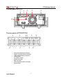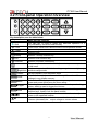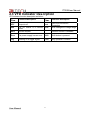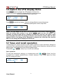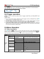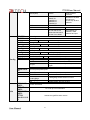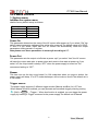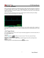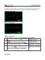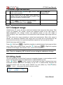
1
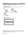
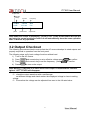
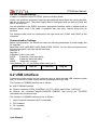
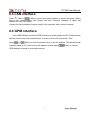
IT7300 User Manual USER MANUAL Programmable AC Power Supply IT7300 Series Model IT7321/IT7322/IT7324 © Copyright All Rights Reserved Ver1.3/Dec, 2013/ IT7320 1 User Manual IT7300User Manual IT7320 Series Programmable AC Power Supplies ........................................................... 3 Security ................................................................................................................................ 3 Security regulation ............................................................................................................. 3 Safety symbols.................................................................................................................... 3 Certification and Quality Assurance ................................................................................. 3 Introduction ........................................................................................................................... 5 Chapter1 Inspection and Installation ..................................................................................... 6 1.1 Inspection .................................................................................................................................................... 6 1.2 Dimension ................................................................................................................................................... 7 Chapter2 Quick start ............................................................................................................. 9 2.1 Front and Rear Panel ................................................................................................................................ 9 2.2 Front-panel Operation Overview............................................................................................................ 11 2.3 VFD Indicator Description ....................................................................................................................... 12 Chapter3 Power on check ................................................................................................... 13 3.1 power on checkout ................................................................................................................................... 13 3.1.1 Power on the supply ..................................................................................................................... 13 3.1.2 System self-test............................................................................................................................. 14 3.2 Output Checkout ...................................................................................................................................... 15 Chapter4 Technical specification ......................................................................................... 16 4.1 Specification.............................................................................................................................................. 16 4.2 Supplementary parameters .................................................................................................................... 19 Chapter5 Basic Operation ................................................................................................... 20 5.1 Local/Remote Mode ................................................................................................................................ 20 5.2 Voltage Setup ........................................................................................................................................... 20 5.3 Frequency Setup ...................................................................................................................................... 21 5.4 Phase Angle Setup .................................................................................................................................. 21 5.5 Output On/Off Operation ......................................................................................................................... 21 5.6 Switch the VFD display items................................................................................................................. 22 5.7 Save and recall operation ....................................................................................................................... 22 5.8 Trigger operation ...................................................................................................................................... 23 5.9 Menu Operation........................................................................................................................................ 23 5.9.1 Menu description .......................................................................................................................... 23 5.9.2 Menu function ................................................................................................................................ 25 5.10 Function operation ................................................................................................................................. 27 5.10.1 Sweep .......................................................................................................................................... 27 5.10.2 List operation(List ) ..................................................................................................................... 29 5.10.3 Dimmer ...................................................................................................................................... 32 5.11 Output range ........................................................................................................................................... 33 5.12 Key lock ................................................................................................................................................... 33 5.13 BNC ......................................................................................................................................................... 34 Chapter6 Remote Operation Mode ............................................................................................ 35 6.1 RS232 interface........................................................................................................................................ 35 6.2 USB interface............................................................................................................................................ 36 6.3 LAN interface ............................................................................................................................................ 37 6.4 GPIB interface .......................................................................................................................................... 37 User Manual 2 IT7300 User Manual IT7320 Series Programmable AC Source Security Please do not install replacement parts in the instrument, or perform any unauthorized modification. Please send the instrument to our company's maintenance department for maintenance, to ensure its security features. Please refer to the manual for specific information warning or precautions to avoid personal injury or equipment damage. There is no part that the operator can maintenance. If maintenance service is required, please contact a trained service personnel. Security regulation To prevent electric shock, non-authorized personnel is strictly not allowed to open the machine. This equipment is strictly prohibited for use in life support systems or any other device with security requirements. We cannot accept responsibility for any direct or indirect financial damage or loss of profit that might occur when using the electronic load. Safety symbols Warning It reminds the user, note some operating procedures, practices, conditions and other matters, that may lead to human casualties. Notes: It reminds the user of some operating procedures, practices, conditions and other matters that may result in instrument damage or data lose for ever. Connect it to safety earth ground using the wire recommended in the user manual. The symbol on an instrument indicates that the user should refer to the operating instructions located in the manual. High voltage danger Certification and Quality Assurance IT7320 series programmable AC power supply fully meet all of the technical specification in the manual. Warranty Our Company gives one year warranty for the materials and manufacturing of the product since the date of shipment. 3 User Manual IT7300User Manual Warranty Service For the warranty service or repair the product, the product must be returned to the designated maintenance units. Return the product to us for warranty service, the customer should pre-pay the one-way Freight to the maintenance department. and our company is responsible for the return shipping cost. If products are returned from other countries for maintenance service, then the customer should pay all freight, duties and other taxes. Guarantee limit The guarantee does not apply to the damage caused by the following conditions: Improper or inadequate maintenance to the products by customer; Customers use their own software or interface; Unauthorized modification or misuse; Operate this product not in the specified environment, or at the wrong place configuration and maintenance. Damage from customer self-installation of circuit, or defects due to customers use their products . Product model or serial number of the fuselage has been altered, deleted, removed or made illegible; Damage caused by accidents including but not limited to lightning, water, fire, abuse or neglect. Notice If the contents of this manual is subject to change, we will not notice additionally User Manual 4 IT7300 User Manual Introduction IT7320 series sets up the new standard for high performance AC power source.It equips with all powerful features such as power line disturbance (PLD) simulation, Dimmer and comprehensive measurement functions.With a compact and standard size of 2U.IT7320 series has built-in LAN/RS232/USB/GPIB communication interface (except IT7321, IT7321 is equipped with LAN/RS232/USB communication interface).These features make the IT7320 series ideal for commercial,power electronics and military test applications from bench-top testing to mass production. Features: High accuracy and resolution Compact and standard size (300VA @ 2U) Programmable frequency:45HZ-500HZ Display Vrms,Irms,Ipeak,frequency,PF,apparent power and active power simultaneously IEC61000-4-11,IEC 61000-4-14,IEC 61000-4-28 voltage dips and frequency variation simulation Power line disturbance simulation capability Programmable voltage and current limit settings Dimmer function Turn on,turn off phase angle control(0-360°) TTL signal which indicates output transient Support front and rear panel output List mode to generate surge,sag and other line disturbance simulations Over-voltage,over-power,over-current,over-temperature protection features Built-in LAN,RS-232, GPIB and USB interface programming with SCPI command language. Memory capacity:10 groups Mode IT7321 IT7322 IT7324 Voltage 300V 300V 300V Current 3A 6A 12A Power 300VA 750VA 1500VA 5 User Manual IT7300User Manual Chapter1 Inspection and Installation Power supply is a kind of high level safety equipment with a protected ground terminal. Before Installation or operation, please read the safety signs and instructions in this manual 1.1 Inspection After receive the power supply, follow these steps to check: 1. Damage When you receive your AC source,inspect it for any obvious damage that may have occurred during shipment.If there is damage,notify the shipping carrier and the nearest ITECH Sales and Support Office immediately. 2.Accessories Make sure you receive the AC source and the following accessories at the same time, if any is missing, please contact your nearest support office. □ a power cord (a power cord appropriate for your location) □ a User’s manual. □ a factory calibration report □ a USB cable 3. AC input There are two kinds of mains input of IT7320 (110Vac and 220Vac). AC input level 110VAC ± 10%, 47 to 63 Hz 220VAC ± 10%, 47 to 63 Hz Power cord type E E E N L L E N N L L China IT-E171 User Manual America,Canada IT-E172 Europe IT-E173 6 N England IT-E174 IT7300 User Manual 1.2 Dimension 1. IT7321 power supply’s dimension: 214.5mmW×88.2mmH×453.5 mmD (W:width H:height * refer to the Dimension below: D:depth) Unit:millimeter 7 User Manual IT7300User Manual 2. IT7322/IT7324 power supply’s dimension: 439mmW×131.4mmH×535.7 mmD (W:width H:height * refer to the Dimension below: D:depth) Unit:millimeter User Manual 8 IT7300 User Manual Chapter2 Quick start This chapter introduces the front panel, the rear panel, key functions and VFD display of the AC source.Make sure that you can quickly know the appearance, instruction and the key function before you operate the power supply, Help you make better use of IT7320 series. 2.1 Front and Rear Panel The front panel of IT7321 ① ③ ④ ② ⑤ ⑥ ⑦ The front panel of IT7322/IT7324 ⑥UP, DOWN, LEFT and RIGHT key ⑦ Output terminals ⑧ Power button ① VFD display ② Rotary knob ③Compound key, the local switch key and power switch ④ Numeric keys and ESC ⑤ Function keys 9 User Manual IT7300User Manual The rear panel of IT7321 ① ② ③ ④ ⑦ ⑥ The rear panel of IT7322/IT7324 ① ② ③ ④ ⑤ ⑥ ⑦ ⑧ ⑨ LAN communication interface RS232 communication interface USB communication interface Cooling fans AC power socket Output terminals BNC terminal GPIB communication interface System Bus User Manual 10 ⑤ IT7300 User Manual 2.2 Front-panel Operation Overview Key description, see the table below: Keys Name and the function The shift key is used to select the alternate operation of a Shift key,indicated by the word under the key Local buton, switch from remote mode to local operation mode Local /Sweep Power on key Numeric keys Number 7/Sweep function key 8 /List Number 8/List function key 9 /*Dimmer Power 0-9 Number 9/Dimmer function key Escape key.It can be used to exit keyboard entry or move up a level in the menu. Set the voltage value/ Switch the voltage range between high range /High/Auto and Auto range mode /Phase Recall /Save /Menu Enter /Trigger On/Off /Lock Set the frequency /set the phase angle Recall the setup from internal memory/ Store the AC source settings in non-volatile memory. Switch the VFD display to be apparent power,peak current,active power and power factor/entry the menu setup Enter key, to confirm the number entered and operation/trigger button, which is used to trigger the List test Output on (off) keys, control power output state / keypad lock function keys, used to lock the panel buttons Left and right direction keys, used to set the value, to adjust the cursor to the specified location Up and down keys, used to turnover the item in the menu or increase (decrease) the output voltage or current values 11 User Manual IT7300User Manual 2.3 VFD Indicator Description VFD indicator function description as follow: Char Function description Char Function description OFF Output is off Prot OVP/OTP/OCP/OPP Protection Rmt The AC source is in remote Auto mode Auto change the voltage range SRQ Service request * Dimmer function is enabled Error The power supply has an error Shift Shift button is pressed Trig Awaiting for a trigger signal Lock Key operation is locked User Manual 12 IT7300 User Manual Chapter3 Power on check This chapter will introduce the procedure of power on check, including pre-check and output check, to make sure the IT7320 series AC source can power on and work normally on the original state. 3.1 power on checkout Before operate the AC source, please read the following safety guide: Warning:The power supply is shipped from the factory with a power-line cord that has a plug appropriate for your location. Your power supply is equipped with a 3-wire grounding type power cord; the third conductor being the ground. The power supply is grounded only when the power-line cord is plugged into an appropriate receptacle. Warning:Use wire with appropriately rated load capacity of all load wires must be able to withstand the maximum short-circuit output current of the power without overheating. If there is more than one load, each load wire must be able to safely carry the power of full rated short-circuit output current. Warning:In order to reduce the risk of fire and electric shock, make sure that the mains supply voltage fluctuations should not exceed 10% of the operating voltage range. Note: In some cases, misconfigurated mains voltage for the instrument may cause the mains fuse disconnected. Power on pre-check includes two parts: power on check and system self check. 3.1.1 Power on the supply Use the following steps to help solve problems you might encounter when turn on the instrument. 1) Verify a good condition of Mains supply connection First, verify that the power cord is firmly plugged into the power receptacle on the rear panel of the AC source. You should also make sure that the power source you plugged the AC source into is energized. Then, verify that the power supply is turned on. 2) Verify the power-line voltage setting. The line voltage is set to the proper value for your country (220VAC or 110VAC) when the power supply is shipped from the factory. 13 User Manual IT7300User Manual 3) Verify that the correct power-line fuse is installed. If the fuse was damaged, please replace the fuse with same specification for your power supply. 4) How to exchange the fuse Remove the AC power cord and open the plastic cover located at the AC power inlet,then you will see the fuse. Replace with a fuse of the same specification and install it. 3.1.2 System self-test After power on,the VFD will display the BIOS version: BIOS VER1.10 After 1s,it will change to display as below: System Selftest….. If the EEPROM was damaged or the latest operation data in EEPROM was lost, the VFD will display with a indicator light of “Error”.Access the menu could check the detailed error information.If everything goes well,VFD will display: User Manual 14 IT7300 User Manual Output state effective voltage Current Frequency OFF 200.0V 0.0mA 60.0 0.00W PF=0.000 0.0S power power factor output time Note:Under the screen of displaying “ITECH IT7321”,press On/Off button will quit the and entry the normal working screen.Or it will automatically done the same operation after 7s without any operation. 3.2 Output Checkout The following procedures check to ensure that the AC source develops its rated outputs and properly responds to operation from the front panel. The following steps verify basic voltage functions without load. 1) Turn on the AC source. 2) Press and numeric key to set a effective voltage,press Enter to confirm and numeric key to set the frequency,press Enter to confirm. 3) Press 4) Press On/Off to turn on the output Note:When On/Off button is lit which means the output is ON,Meanwhile indicator light of “OFF” on VFD will disappear. 5) check the output waveform with a oscilloscope set different voltage and check wether the disiplayed voltage is close to setting voltage. 6) Ensure that the voltage can be adjusted from zero to the full rated value 15 User Manual IT7300User Manual Chapter4 Technical specification This chapter will introduce the main technical parameters of IT7300,such as rated voltage/current/power and so on. Besides, this part will introduce the working environment and storage temperature. 4.1 Specification Model IT7321 AC INPUT Input Phase Voltage Frequency Max.Current Power Factor AC output Max.Power Max Current(rms) Max Current(peak) Phase Total Harmonic Distortion(T.H.D) Crest Factor Line Regulation Load Regulation Response Time Voltage Frequency Phase Angle Range Resolution Accuracy Range 1 110Vac±10%;220Vac±10% 47-63Hz 8A 0.5(typical) AC OUTPUT 300VA 3.0A(0-150V) 1.5A(0-300V) 12A (0-150V) 6A(0-300V) 1Φ/2W ≤0.5% at 45-500Hz (Resistive Load) ≧4 0.1% max for a ±10% line change ≤0.5%FS (Resistive Load) <100uS SETTING 0-300V, 150/300V Auto 0.1V ±(0.2% +0.6V) 45-500Hz 0.1Hz at 45-99.9Hz 1Hz at 100-500Hz 0.1HZ 0-360° 0.1° ±1°(45-65Hz) Resolution Accuracy Range Resolution Accuracy READBACK Voltage Current(rms) Current(peak) User Manual Range Resolution Accuracy Range Resolution Accuracy Range Resolution Accuracy 0-300V 0.1V ±(0.2% + 0.6V) L:120.0mA/ M:1.200A/ H:3.00A * L:0.1mA/ M:1mA/ H:10mA L: ±(0.2%+0.4mA)/ M: ±(0.2%+4mA)/ H: ±(0.2%+20mA) 0-12A 0.01A ±(1% + 120mA) 16 IT7300 User Manual Resolution Power Accuracy Memory Sync Output Signal Interface Operation Environment Dimension Weight L:0.01W/ M:0.1W/ H:1W L: ±(0.2%+0.05W) (47HZ-65HZ)/ M: ±(0.2%+0.5W) (47HZ-65HZ) / H: ±(0.2%+2W) (47HZ-65HZ) OTHER SPECIFICATION 10 memories Output Signal 5V, BNC type LAN, USB, RS232 0-40℃/20-80%RH 214.5mmW×88.2mmH×453.5mmD 9.5kg Model IT7322 AC INPUT Input Phase Voltage Frequency Max.Current Power Factor AC output Max.Power Max Current(rms) Max Current(peak) Phase Total Harmonic Distortion(T.H.D) Crest Factor Line Regulation Load Regulation Response Time Voltage Frequency Phase Angle Range Resolution Accuracy Range 1 110Vac±10%;220Vac±10% 47-63Hz 15A 0.7(typical) AC OUTPUT 750VA 6A(0-150V) 3A(0-300V) 24A (0-150V) 12A(0-300V) 1Φ/2W ≤0.5% at 45-500Hz (Resistive Load) ≧4 0.1% max for a ±10% line change ≤0.5%FS (Resistive Load) <100uS SETTING 0-300V, 150/300V Auto 0.1V ±(0.2% +0.6V) 45-500Hz 0.1Hz at 45-99.9Hz 1Hz at 100-500Hz 0.1HZ 0-360° 0.1° ±1°(45-65Hz) Resolution Accuracy Range Resolution Accuracy READBACK Voltage Current(rms) Current(peak) Range Resolution Accuracy Range Resolution Accuracy Range 0-300V 0.1V ±(0.2% + 0.6V) L:120.0mA/ M:1.200A/ H:6.00A * L:0.1mA/ M:1mA/ H:10mA L: ±(0.2%+0.4mA)/ M: ±(0.2%+4mA)/ H: ±(0.2%+20mA) 0-24A 17 User Manual IT7300User Manual Resolution Accuracy Resolution Power Accuracy Memory Sync Output Signal Interface Operation Environment Dimension Weight 0.01A ±(1% + 120mA) L:0.01W/ M:0.1W/ H:1W L: ±(0.2%+0.05W) (47HZ-65HZ)/ M: ±(0.2%+0.5W) (47HZ-65HZ) / H: ±(0.2%+2W) (47HZ-65HZ) OTHER SPECIFICATION 10 memories Output Signal 5V, BNC type LAN, USB, RS232, GPIB 0-40℃/20-80%RH 439mmW×131.4mmH×535.7mmD 40kg Model IT7324 AC INPUT Input Phase Voltage Frequency Max.Current Power Factor AC output Max.Power Max Current(rms) Max Current(peak) Phase Total Harmonic Distortion(T.H.D) Crest Factor Line Regulation Load Regulation Response Time Voltage Frequency Phase Angle Range Resolution Accuracy Range 1 110Vac±10%;220Vac±10% 47-63Hz 30A 0.7(typical) AC OUTPUT 1500VA 12.0A(0-150V) 6A(0-300V) 48A (0-150V) 24A(0-300V) 1Φ/2W ≤0.5% at 45-500Hz (Resistive Load) ≧4 0.1% max for a ±10% line change ≤0.5%FS (Resistive Load) <100uS SETTING 0-300V, 150/300V Auto 0.1V ±(0.2% +0.6V) 45-500Hz 0.1Hz at 45-99.9Hz 1Hz at 100-500Hz 0.1HZ 0-360° 0.1° ±1°(45-65Hz) Resolution Accuracy Range Resolution Accuracy READBACK Voltage Current(rms) User Manual Range Resolution Accuracy Range 0-300V 0.1V ±(0.2% + 0.6V) L:120.0mA/ M:1.200A/ H:3.00A * 18 IT7300 User Manual Current(peak) Power Resolution Accuracy Range Resolution Accuracy Resolution Accuracy Memory Sync Output Signal Interface Operation Environment Dimension Weight L:0.1mA/ M:1mA/ H:10mA L: ±(0.2%+0.4mA)/ M: ±(0.2%+4mA)/ H: ±(0.2%+20mA) 0-48A 0.01A ±(1% + 120mA) L:0.01W/ M:0.1W/ H:1W L: ±(0.2%+0.05W) (47HZ-65HZ)/ M: ±(0.2%+0.5W) (47HZ-65HZ) / H: ±(0.2%+2W) (47HZ-65HZ) OTHER SPECIFICATION 10 memories Output Signal 5V, BNC type LAN, USB, RS232, GPIB 0-40℃/20-80%RH 439mmW×131.4mmH×535.7mmD 40kg *Description about the switch of current range: When switch from low to high level(L to M,M to H) happened at the condition of Ipeak>300%(Full rms), When Ipeak>300%(Full rms),the current switch from low range to high range(L to M,M to H). When Ipeak<20%(Full rms),the current switch from high range to low range(H to L). When Ipeak<80%(Full rms),the current switch from high range to Middle range(H to M). 4.2 Supplementary parameters Memory :10 groups suggested calibrationfrequency: 1time/year Radiating mode : Fans Operation temperature: 0 to 40 °C Storage temperature: -20 to 70 °C. Humidity : Max humidity: 80% 19 User Manual IT7300User Manual Chapter5 Basic Operation This chapter introduce the basic operations of IT7320 series AC sourece,including the following parts: Local/remote mode Voltage setup Frequency setup Phase angle setup Output on/off operation Switch the VFD display items Save/recall operation Trigger operation Menu operation Switch output voltage range Key lock function BNC terminals function 5.1 Local/Remote Mode to change the AC source from remote to local operation. Press the local button After you power on the AC source, it defaults in local mode, all buttons are enabled. While in remote mode, most buttons are disabled except Shift and Local keys.In addition, the mode modificaton will not effect the output parameters. 5.2 Voltage Setup You can set voltage within the range of rated voltage value. When you press button, the button will be lit. This indicates that you can set voltage. There are three ways to set output voltage through front panel. The first way: press ,adjust cursor location through button, pressing and will enable you to increase or decrease the setting voltage value. The second way: press rotary knob button, adjust to change the setting voltage value. The third way: press User Manual , adjust cursor location through button and numeric key( 20 0 to 9 ) to set voltage value IT7300 User Manual 5.3 Frequency Setup You can set frequency within the range 45Hz to 500Hz. When you press , the button will be lit. This indicates that you can set frequency.There are three ways to set frequency through front panel. ,adjust cursor location through button, pressing The first way: press and will enable you to increase or decrease the setting frequency value. , adjust cursor location through The second way: press rotary knob button, adjust to change the setting frequency value. The third way: press button and numeric key( 0 to 9 ) to set frequency value 5.4 Phase Angle Setup You can set the starting and stop phase angle within range of 0~360° by pressing (Shift)+ (Phase),VFD will display as below: OFF 0.0V Start 0.0mA Phase= 0.0° 50.0 0.6S Press numeric keys to set the starting phase angle and press Enter to confirm.Then the VFD will indicate next operation to set stop phase. OFF 0.0V Stop 0.0mA Phase= 0.0° 50.0 0.6S 5.5 Output On/Off Operation On/Off button is used to control the output state of AC source. When On/Off button is lit,.It indicates the output in on state.When output button is dark which means the output is turned off. Note: make sure you have connected AC source and test DUT very well, then press On/Off button to minimize shock hazard. 21 User Manual IT7300User Manual 5.6 Switch the VFD display items Press button to change the VFD display of bottom line. Default VFD display:effective voltage,effective current,frequence Active power,power fator,output time OFF 0.0V 0.00W Press 0.0mA PF= 0.000 50.0 0.0S to switch the display: effective voltage,effective current,frequence apparent power,peak current,output time OFF 0.0V 0.00VA 0.0mA 50.0 0.00Apk 0.0S Notes: The time shown on the VFD is the output time of AC source. Press On/Off to start the timing when power is on; press On/Off again to turn off power. The duration of power supply will be displayed on the VFD until the next power starts when the timer will reset. The timing is based on the decimal system: when the time reaches 999.9 s, the timing will be displayed in minutes (m); when the time reaches 999.9 m, the timing will be displayed in hours (h). 5.7 Save and recall operation IT7320 series AC source provides10 non-volatile registers to save instrument settings for recall later.Each operating state includes preset voltage, preset frequency, starting and stop phase angle, output range level and dimmer phase angle. Press(Shift) + Recall (Save) key to recall /save settings. Save operation: + Recall (Save).You’ll be To save the instrument’s settings to a register,press shift prompted for a register number.Enter a number between 0 and 9,then press the Enter key.The setting are saved. OFF 2.0V 0.0mA Save data bank=0 User Manual 50.0 0.0S 22 IT7300 User Manual Recall operation press Recall button.You’ll be prompted for a register number.Enter a number between 0 and 9,then press the Enter key.The setting are recalled. OFF 2.0V 0.0mA Recall data bank=0 50.0 0.0S 5.8 Trigger operation IT7320 series AC source has three kinds of trigger modes.They are Manual,BUS and EXTEN. Trigger modes: 1) To use front panel trigger mode,first set the trigger source as Manual.Press shift +Enter (trigger) to start panel trigger mode. 2) The BNC trigger connectors on the rear panel let you apply trigger signals to the AC source.To use external trigger mode,first set the trigger source as EXTERN. 3) To use BUS trigger mode,first set the trigger source as BUS.Connect AC source by USB,RS-232 or LAN communication interface.When the TRIG command is received,the AC source will produce a trigger signal. 5.9 Menu Operation 5.9.1 Menu description Press (Shift)+ (Menu)to enter menu.View the menu on the VFD,and use the direction keys or the knob to scroll through the complete menu listed below.Press Enter to enter the selected menu function,press ESC to return to the previous menu. MENU Init Power-On Power-Out Syste m Buzzer Trigger Communica tion Initialize system menu POWER-ON PARAMENT Sav0(Def) Rst POWER-OUT Off(Def) Last BUZZER On(Def) Off TRIGGER SOURCE Manual(Def) Bus Extern COMMUNICATION 23 Set the Power ON/OFF state after power up. The preset parameter stored in group 0 Factory Default Power on state set In the state of power off In the state of latest power-off state Set buzzer state Buzzer on Buzzer off Trigger source selection. Manual trigger Bus trigger External trigger Communication interface and parameter setting User Manual IT7300User Manual RS232(Def) RS232 4800,8,N,1 9600,8,N,1 19200,8,N,1 38400,8,N,1 57600,8,N,1 Select USB interface LAN Gateway=192.168.0.1 IP=192.168.0.125 Mask=255.255.255.0 Socket Port=30000 USB LAN CONFIG Volt-Min Volt-Max Freq-Min Freq-Max Irms-Protect Config BNC-Set Config menu Voltage lower limit Volt-Min=0.0V Voltage upper limit Volt-Max=300.0V Frequency lower limit Freq-Min=45.0Hz Frequency upper limit Freq-Max=500.0Hz Current RMS protect point Irms-Protect=12.000A BNC PORT SETUP I-Trigger I-On O-Sync O-On Ipeak-Prote ct Dimmer Ipeak-Protect=12.000A DIMMER PRODUCT Power information INFO: ERROR INFO: PRODUCT INFO: IT7321 Ver:0.01~0.0 1 User Manual Set Baud rate,data bit,odd-even check,stop bit and address Select LAN interface Set gateway, IP address, mask address and port. Set Min. voltage Set Max, voltage Set frequency upper limit Set current RMS protect point Input interface for external trigger Input interface for on/off control Output interface for AC phase synchronization signal Output interface for on/off state interface Current peak protect point Set Current peak protect point Phase dimmer LeadingEdge Phase dimmer function LeadingEdge TrailingEdge Off Info Select RS232 interface TrailingEdge Phase dimmer function Disable Phase dimmer function For look up error information Instrument type/Firmware version 24 IT7300 User Manual 5.9.2 Menu function 1. System menu Initialize the system menu relative factory default setup as follows: Power-On Power-Out Buzzer Trigger Communication Sav0 Off On Manual RS232 Power-On This parameter determines the state of the AC source after power up.If you select “Rst”,the default output parameter settings will be active after power up.The default setup is 0V,50HZ, 0° and 0°.If you select “Sav0”,then the AC source will automatically recall the output parameters setting saved in 0 register.. Note,please save these parameters in memory0 according to 5.7. Power-Out This parameter sets the output on/off state at power up.If you select “Last”,the AC source will save the output state prior to power down and revert to that state at power up.If you select “off”,the output state is always “OFF” when the power supply is turned on.The recommend setting is “OFF”. Buzzer This item can set the key sound state.If in ON mode,then when you press a button, the power supply will beep. If in OFF mode,the beeper will not make a sound.The default set is in ON mode. Trigger source The power supply supports 2 different trigger modes (Manual and Bus) for LIST test. When Manual mode is enabled, you can generate an immediate trigger pulse by presing (Shift)+ Enter (Trigger).When bus function is enabled, you can trigger the power supply by sending a Trigger command to the power supply.The default set is Manual 25 User Manual IT7300User Manual Communication There are three types of communication interfaces available:RS-232,USB and LAN.You can choose any one of them to communicate with a PC. RS232 interface Avaiable baudate:4800, 9600, 19200, 38400, 57600, 115.2K Data bit:8 Parity bit:NONE,ODD,EVEN Address:0-31 LAN interface Parameters need to be configured in LAN mode. Gateway, IP address, Mask address and socket port. Before communicating with the principal computer, choose the communication port and perform associated configuration to ensure that communication configuration of the power accords with that of the principal computer. 2. Config menu Volt-Min: Volt-Max: Voltage lower limit setting Freq-Min: Freq-Max: Frequency lower limit setting Frequency upper limit setting Irms-Protect: Ipeak-Protect: Current RMS upper limit setting Peak Current upper limit setting Voltage upper limit setting 3. Instrument information Step 1 2 Operation Press (Shift)+ (Menu)to enter menu operation press right direction key to select INFO,press Enter User Manual 26 VFD display MENU System Config Info PRODUCT INFO: IT7321 Ver:0.06~0.06 IT7300 User Manual 5.10 Function operation 5.10.1 Sweep The Sweep function is used to test efficiency of switching power supply and capture the voltage and frequency at the maximum power point. The voltage and frequency of power may be altered in the form of step ladder by setting the initial voltage, final voltage, step voltage, initial frequency, final frequency, step frequency and one-step time. The one-step time may be indicated in seconds, minutes or hours. A maximum of 10 files may be stored. As the test closes, voltage, frequency and current at the maximum power point may be displayed. > Edit sweep file Note: In the following operations, up and down keys are used to turn over steps, but not to increase or decrease value.When up arrow appears in the lower left corner,you can press the up key to jump to the previous step.When down arrow appears in the lower right corner,press down key can entry the next step. STEP OPERATION 1 Press (Shift)+ (Sweep)to enter menu operation 2 Press Enter to confirm when Edit is shining. 3 4 5 6 7 8 9 10 11 12 VFD DISPLAY SWEEP Edit Recall Disable START VOLTAGE Voltage= 0.0V Press number key or knob to set start voltage, press END VOLTAGE Enter to confirm Voltage= 0.0V Press numeric key or knob to set stop voltage, press STEP VOLTAG Enter to confirm Voltage=0.1V Press numeric key or knob to set step voltage, press TIME UNIT Enter Second Minute Hour to confirm STEP TIME Press left and right arrow keys to select time unit Enter to confirm Time=2.0S second, minute and hour, press START FREQUENCY Set step last time(0.1s~999.9s),press Enter to Frequency=50.0Hz confirm Enter Set start frequency(45Hz~500Hz), press to END FREQUENCY Frequency=50.0Hz confirm Set stop frequency(45Hz~500Hz), press Enter to STEP FREQUENCY Frequency=1.0Hz confirm SWEEP SAVE Set step frequency,press Enter to confirm No Yes Press left and right arrow keys to select whether SWEEP SAVE save sweeping file,” No” means do not saving ,” Yes” Save data bank=0 means saving. Select save position(0~9), press Enter to confirm, SWEEP Edit Recall Disable VFD display “SaveData success! “ for 1 second. 27 User Manual IT7300User Manual >Recall sweep file STEP OPERATION 1 Press multiple keys (Shift)+ (Sweep) to menu operation 2 Press right arrow key then press Enter key to confirm when Recall key is shining. 3 Press numeric key to select needed recall file and press Enter key to confirm. VFD display “Recall Data success! “ for 1 second. VFD DISPLAY SWEEP Edit Recall Disable RECALL SWEEP Recall Sweep=0 SWEEP Edit Recall Disable > Set sweep test state and start test STEP OPERATION 1 Press multiple keys (Shift)+ (Sweep) to menu. 2 Press right arrow key to “Disable”, press down arrow key and Enter to infirm when “Disable” is shining. the words”Sweep” appears at the right bottom,which means the Sweep function is active. 3 Press On/Off key to start sweep test. Enter key will shining during test and will stop after that with power off automatically. VFD DISPLAY SWEEP Edit Recall Disable To exit Sweep test function STEP OPERATION VFD DISPLAY 1 SWEEP Press multiple key (Shift)+ (Sweep) to menu Edit Recall Enable operation. 2 Press right arrow key to “Enable”, press down arrow key and Enter key to confirm and then exit sweep function(Sweep words will disappeared on lower right of VFD display ) User Manual 28 IT7300 User Manual 5.10.2 List operation With List operation applied to the alternating power supply, alternating waveform sequences in various ranges may be output. The surge/trapped wave may be added as required to simulate fluctuation of network voltage so as to evaluate the test result of the instrument under such situation. Various alternating sequences with output varied may be formed by listing the voltage, frequency, slope, surge/trapped wave each step. . Surges wave List sequences of IT7320 series can be stored into a non-volatile register,with a capacity of 100 steps.The user can edit up to 10 files.Following shows how to edit,recall and run a list file: > Set Trigger Source The surge/trapped wave test of LIST may be manually triggered to control the start time of the surge/trapped wave. Operation: (1)Press (Shift)+ (Menu) to entry the menu. Then the system will keep flickering------press Enter to confirm. (2)Press right key to select Trigger.When selected,trigger item will be twinkling.Press Enter to confirm. (3)Press right key to select Manual and press Enter to confirm. 29 User Manual IT7300User Manual >Edit LIST File Steps Operation 1 Press (Shift)+ 8 (List) button,select Edit,press Enter to confirm. 2 Press numeric key,set the step counts(range:1~100),press Enter to confirm. 3 Press numeric key,set number of cycles(range:1~1000),press Enter to confirm. 4 Set the first step voltage and press Enter to confirm. 5 Set the first step frequency and press Enter to confirm. 6 Set the slope(0.1~999.9),press Enter to confirm. 7 Set the time unit:S,min,hour,press Enter to confirm. 8 Set delay time(0.1~999.9),press Enter to confirm. 9 Disable or enable the surges or trap state,press Enter to confirm.If select Disable,then do nothing for step10-step12. Press left/right key to set whether create surges/wave traps continouly.If select Yes,power supply will create surges/wave traps in at intervals of 100ms.Press Enter to confirm. Press numeric keys to set voltage of surges/wave traps,press Enter to confirm.If set voltage is higher than current working voltage,then it is surges,or it is wave traps. Set the starting time of surges/wavetraps,press Enter to confirm.With the restriction of frequency,the max settable time is 20ms. Set the duration time of surges/wave traps.Press Enter to confirm. Repeat step4-13. 10 11 12 13 14 15 16 NO:Do not save the list file,after power off the unit,current file will lose. Yes:Save list file to assigned memory room for quickly recall at any time. Store file to specified storage space(0~9 groups),press Enter to confirm.VFD will display “Save data success!” User Manual 30 VFD display LIST Edit Recall Disable STEP COUNT Step Count=0 LIST REPEAT List Repeat=0 LIST VOLTAGE Step 0 Voltage=0.0V LIST FREQUENCY Step 0 Frequency=0.0Hz LIST SLOPE Step 0 Slope=0.0S DWELL UNIT Second Minute Hour LIST DWELL Step 0 Dwell=0.0S SD STATE Disable Enable SD CONTINUE No Yes SD VOLTAGE Step 0 Voltage=0.0V SD SITE Step 0 Site= 0ms SD TIME Step 0 Time=0ms LIST VOLTAGE Step 1 Voltage=0.0V LIST SAVE No Yes LIST SAVE Save data bank=0 IT7300 User Manual > Set LIST State steps operation 1 Press (Shift)+ 2 VFD display 8 LIST (List) to entry the List menu. Edit Recall Disable Press right key to select Disable,when it flicker,press LIST Edit Recall Enable up/down key to select Enable,and press Enter to confirm.Now the List mode is enabled.Escape menu,the front panel will display “LIST 0”. > Run LIST File After enable the List mode,press On/Off to turn on the output,it will begin to run.Meanwhile,you will see Enter button keep flickering.The output will vary according to the edited steps. Press On/Off button can quit the running state of List file. > Quit LIST Mode Steps Operation 1 Press (Shift)+ 2 8 (List) to entry the List menu. Press right key to select Enable,when it flicker,press up/down key to select Disable,and press Enter to confirm. VFD display LIST Edit Recall Enable LIST Edit Recall Disable >Recall LIST Mode When several List files are stored into the non volatile memory,user can recall the assigned file by Recall operation. Steps Operation 1 Press (Shift)+ 8 (List)button to entry the List menu 2 Press right key to select Recall,when it flicker,press Enter to confirm.Press the file number to recall the assigned file.Press Enter to confirm. 3 When recall successfully,the VFD will display”Recall data success!”. VFD display LIST Edit Recall Disable RECALL LIST Recall List=0 LIST Edit Recall Disable After recall,please enable the LIST state,then quit the menu and press ON/OFF to trigger the execution. 31 User Manual IT7300User Manual 5.10.3 Dimmer The leading and lagging edge of the waveform can by concealed and the phase angle set with Dimmer function to regulate the active power, thus adjusting the lighting intensity. Dimmer of leading edge: Dimmer of lagging edge: Dimmer operation: > Active dimmer function, set LeadingEdge /LaggingEdge 1 2 3 4 Press multiple keys (Shift)+ (Menu)to menu Press right arrow key to select “ Config”, press Enter to confirm when “Config” is shining Press right arrow key to “Dimmer” press Enter to confirm when “Dimmer” is shining. MENU System Config Info CONFIG Volt-Min Volt-Max > DIMMER LeadingEdge TrailingEdge Off Select “LeadingEdge” or “LaggingEdge” to active the DIMMER LeadingEdge TrailingEdge key to confirm when it is function. Press Enter Off shining. Shining”*” indicate on VFD means dimmer function is in used, conversely,”*” disappeared. User Manual 32 IT7300 User Manual > Set phase angle and start test 1 Press compound key enter menu operation 2 Press numeric key to set angle, press Enter to confirm. Also you can adjust angle by knob to view real-time waveform changes along . 3 and numeric key to set voltage Press based on requirement. Press Enter Power source output dimmer wave with “*” shining. 4 (Shift)+ 9 (*Dimmer)and OFF 9.0V 0.0mA 50.0 Dimmer=30.0° 5.11 Output range IT7320 series AC source will allow switchover between High range and Auto range. Take IT7321 as example, the voltage, current and apparent power at the High range is 300V/1.5A/300VA; the voltage, current and apparent power at the Low range is 150V/3A/300VA. Auto range refers to auto switchover mode between High range and Low range. You can choose the range according to actual test requirements. When Auto range is chosen, the switchover between High range and Low range will be performed by the instrument automatically, thus sparing complicated operations such as manual setting. Switch High range and Auto range: Press (Shift) and (High/Auto) together to switch between High range and Auto (Shift) and range. When High range is chosen, press the to switch to Auto range. The indicator “Auto” on the VFD will be on. (High/Auto) together Note: There is a temporary OFF to the AC source during the switchover of range 5.12 Key lock The front panel keys can be locked to prevent unwanted changes to output settings and AC source configurations.Follow the steps below to enable/disable key lock. ( (Shift)+ On/Off (Lock)button to set the key lock state.If keyboard has been Press locked,the indicator light ”Lock” will display on the VFD .In addition,when keyboard are locked,all buttons can’t be used except ON/OFF key and (Shift) key. Press (Shift)+ On/Off (Lock) once again will relieve key lock function. OFF 0.0V 0.00W 0.0mA PF=0.000 50.0 Lock 33 User Manual IT7300User Manual 5.13 BNC There is a composite terminal at the rear panel of the AC source(see description of rear panel), which can be used as: 1. Input signal: I-Trigger: serve as input signal by external trigger. Connect the positive and negative end of the terminal to generate a trigger signal I-On: serve as the control signal for On/Off. When the positive and negative end of the terminal is in short circuit, the status of AC source is On; when the circuit is open, the status of AC source is OFF 2. Output signal: O-Sync: as synchronizing signal of alternating phase O-On: as status signal for On/Off. When the status of AC source is ON, the terminal will output high level; when the status of power supply is OFF, the terminal will output low level Before using BNC terminal,you need to define its function firstly by following steps below: MENU 1 (Shift)+ (Menu)to Press multiple key System Config Info menu operation. 2 3 4 Press right arrow key and select “config”, press Enter key when “Config” is shining. Press right arrow key to BNC-Set and press Enter key when “BNC-Set” is shining. Press left and right arrow keys to select interface function and press Enter . Press ESC key to exit menu. User Manual 34 CONFIG V-Min V-Max > BNC PORT SETUP I-Trigger I-On O-Phase O-On > IT7300 User Manual Chapter6 Remote Operation Mode IT7320 series AC source has three standard communication interface: RS232, USB, LAN.You can choose any one of them to communicate with PC. 6.1 RS232 interface There is a DB9 connector at the rear of the power supply, when connect to computer, you need to select a cable with COM port on both side; To active communication,you need to enable the settings in menu to be the same with the PC communication configuration. Note:The RS232 settings must match the settings in front panel system information. If any change, please press (Shift)+ (Menu)key to modify the menu: SYST SET\COMM. RS-232 data format RS-232 data is a 10-bit word with one start bit and one stop bit.The number of start bit is not programmable.Stop bit is selectable between 1&2.Besides,you can set the parity bit in the menu using the front panel (Shift)+ key. Parity options are stored in a non-volatile memory. Baud Rate The front panel (Shift)+ button allows the user to set baud rate which is stored in the non-volatile memory: 4800,9600,19200 38400,57600,115200 RS-232 connection cable Adopt the RS232 cable with DB-9 interface because the serial port of RS232 can be connected with that of the controller (e.g. PC). The modulating cable of the air-conditioner is not recommended. The pins of plug are shown as the following table. If your computer is provided with a RS232 interface with DB-25 plug, a cable and a adapter with DB-25 plug (one end) and DB-9 plug (the other end) are required (not the modulating cable of the air-conditioner) Pin number Description RS-232 plug pins 1 No connection 2 TXD, transfer date 3 RXD, receive data 4 No connection 5 GND, ground 6 No connection 7 CTS, clear transfer 8 RTS, ready to transfer 9 No connection 35 User Manual IT7300User Manual RS-232 Troubleshooting: In case of connection failure of RS232, perform following check: Check if the computer and power supply are provided with same Baud rate, parity check bit, data bit and flow control. The power supply shall be configured with one start bit (fixed) and one or two stop bits. Just as described in the RS232 connector, appropriate interface cable or adapter shall be adopted. Notes: even if the cable is equipped with right plug, internal wiring may be incorrect. The interface cable must be connected to the right serial port (COM1 and COM2) of the computer. Communication Settings Before communication, you should first make the following parameters of power supply and PC matches. Baud Rate: 9600 (4800,9600,19200,38400,57600,115200). You can enter the system menu from the front panel, and then set the baud rate. Data bits: 8 Stop Bits: 1 Calibration (none, even, odd) EVEN 8 data bits, have even parity ODD 8 data bits have odd parity NONE 8 data bits, no parity Local Address: (0 ~ 31, the factory default setting is 0) Parity=None Start Bit 8 Data Bits Stop Bit 6.2 USB interface Connect the power supply and the computer using a cable with two USB interfaces (each end). All functions of power supply may be programmed through USB. The functions of USB488 interface are as follows 488.2 USB488 Interface. Receive requests of REN_CONTROL, GO_TO_LOCAL and LOCAL_LOCKOUT. Receive the command MsgID=TRIGGER USBTMC and convey the TRIGGER command to the functional layer. The functions of USB488 component are as follows: 1. Able to read all compulsory SCPI commands. 2. SR1 enabled. 3. RL1 enabled. DT1 enabled. User Manual 36 IT7300 User Manual 6.3 LAN interface Press (Shift) + (Menu) on the front panel together to access the menu. Select LAN in the Communication from System and then configure Gateway, IP, Mask and SocketPort in the LAN option. Connect the LAN interface of power supply to the computer with a reticle (crossed). 6.4 GPIB interface Use a IEEE488 bus to connect GPIB interfaces of power supply and PC. Please ensure that the screws have been screwed down in order to have a full connection. Then press + (Menu) to enter the system menu to set the address. The address range of power supply is 0-31.After you set the address, please press button to confirm, GPIB address is saved in nonvolatile memory. 37 User Manual IT7300User Manual Support process If you have a problem, follow these steps: 1 Check the documentation that come with the product 2 Visit the ITECH online service Web site is www.itechate.com ,ITECH is available to all ITECH customers. It is the fastest source for up-to-date product information and expert assistance and includes the following features : Fast access to email AE Software and driver updates for the product Call ITECH support line 4006-025-000 User Manual 38