1
Stratos®Pro A2... PH
User Manual
Latest Product Information:
www.knick.de
Warranty. Disposal. About This Manual.
Warranty
Defects occurring within 3 years from delivery date shall be remedied
free of charge at our plant (carriage and insurance paid by sender).
Sensors, fittings and accessories: 1 year.
Subject to change without notice.
Return of products under warranty
Please contact our Service Team before returning a defective device.
Ship the cleaned device to the address you have been given.
If the device has been in contact with process fluids, it must be decontaminated/disinfected before shipment. In that case, please attach
a corresponding certificate, for the health and safety of our service
personnel.
Disposal
Please observe the applicable local or national regulations concerning
the disposal of “waste electrical and electronic equipment”.
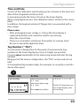
About this manual:
This manual is intended as a reference guide to your device –
You don't have to read the book from front to back.
Take a look at the Table of Contents or the Index to find the function
you are interested in. Each topic is explained on a double-page spread
with step-by-step instructions on how to configure the desired function. Clearly legible page numbers and headlines help you to quickly
find the information:
Configuration
Configuration
Autoclaving Counter
ISM Sensor
Autoclaving counter
1) Press any arrow key.
2) Select CONF using keys,
press enter.
3) Select parameter set using keys,
press enter.
4) Select SENSOR menu using keys,
press enter.
5) All items of this menu group are indicated by
the “SNS:” code.
Press enter to select menu,
edit using arrow keys (see next page).
Confirm (and proceed) by pressing enter.
6) Exit: Press meas key until the [meas] mode
indicator is displayed.
Left page:
How do I get to
the function
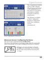
After reaching a specified limit value the autoclaving counter generates a Sensoface message. As soon as the counter has reached
the specified value, Sensoface is getting “sad”. Pressing the info key
shows the text “AuToCLAVE CYCLES oVERRuN” which reminds you
that the maximum number of autoclaving cycles has been reached.
After each autoclaving process, you must manually increment the
autoclaving counter in the SENSoR service menu on the transmitter.
The transmitter displays “INCREMENT AuToCLAVE CYCLE” as confirmation. You can configure the current outputs so that a Sensoface
message generates a 22-mA error signal, see page 63.
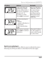
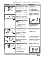
Menu item
Action
Choices
Autoclaving counter Select using keys:
oN:
The cycles are specified
manually (0 ... 9999)
Press enter to confirm.
Select sensor type
Temperature unit
Temp detection during measurement
(Manual temperature)
Temp detection during calibration
(Manual temperature)
Calibration mode
(AuTo: Buffer set)
ACT - Adaptive calibration timer
TTM - Adaptive maintenance timer
CIP/SIP cycles
Autoclaving counter
56
2
With the autoclaving counter switched on, you must increment the
count after each autoclaving process in the SERVICE menu SENSoR/
AuToCLAVE :
After having completed
Incrementing the
autoclaving counter an autoclaving process,
open the SERVICE menu
(SERVICE menu)
SENSoR / AuToCLAVE to
increment the autoclaving count.
To do so, select “YES”
and confirm by pressing
enter.
57
Right page:
Which settings
are provided for
this function
Documents Supplied
Specific Test Report
CD-ROM
Complete documentation:
• User manuals
• Safety instructions
• Certificates
• Short instructions
Safety Information
In official EU languages and others.
• EC Declarations of Conformity
Certificates
•
•
•
•
•
•
IECEx
ATEX
FM
CSA
NEPSI
GOST
Short Instructions
First steps after installation:
• Operation
• Menu structure
• Calibration
• Error messages and recommended actions
In German, English, French, Russian, Spanish,
Portuguese, Italian, Swedish and Dutch.
More languages on CD-ROM and on our
website: www.knick.de
3
Contents
Documents Supplied............................................................................... 3
Introduction.............................................................................................. 7
Intended Use.....................................................................................................7
Safety Information................................................................................. 10
Overview of Stratos Pro A2... PH......................................................... 12
Assembly.................................................................................................. 13
Package Contents..........................................................................................13
Mounting Plan, Dimensions......................................................................14
Pipe Mounting, Protective Hood.............................................................15
Panel Mounting..............................................................................................16
Installation............................................................................................... 17
Installation Instructions..............................................................................17
Rating Plates / Terminal Assignments...................................................18
Wiring of Stratos Pro A2... PH....................................................................19
Wiring Examples............................................................................................21
User Interface, Keypad.......................................................................... 32
Display...................................................................................................... 33
Signal colors (display backlighting)........................................................33
Measuring Mode...........................................................................................34
Selecting the Mode / Entering Values...................................................35
Display in Measuring Mode................................................................. 36
Color-Coded User Interface.................................................................. 37
Operating Modes.................................................................................... 38
Menu Structure of Modes and Functions.............................................39
HOLD Mode.....................................................................................................41
Alarm..................................................................................................................42
Alarm and HOLD Messages.......................................................................43
Configuration.......................................................................................... 44
Menu Structure of Configuration............................................................44
Manual switchover of parameter sets A/B...........................................46
Parameter Sets (Original for Copy).........................................................52
4
Contents
Sensor................................................................................................................54
Current Output 1...........................................................................................70
Current Output 2...........................................................................................78
Temperature Compensation.....................................................................80
CONTROL Input..............................................................................................84
Alarm Settings................................................................................................88
Time and Date................................................................................................92
Tag Number ...................................................................................................92
Digital Sensors........................................................................................ 94
Memosens Sensors: Calibration and Maintenance in the Lab.....94
Memosens Sensors: Configuring the Device .....................................95
Replacing a Sensor.......................................................................................96
Calibration............................................................................................... 98
Selecting a Calibration Mode...................................................................99
Zero Adjustment (ISFET).......................................................................... 100
Automatic Calibration (Calimatic)........................................................ 102
Manual Calibration with Buffer Entry................................................. 104
Data Entry of Premeasured Sensors.................................................... 106
Product Calibration (pH).......................................................................... 108
ORP (Redox) Calibration........................................................................... 110
Temp Probe Adjustment.......................................................................... 112
Measurement........................................................................................113
Diagnostics............................................................................................114
Service....................................................................................................119
Operating States...................................................................................122
A2...X: Supply Units and Connection................................................123
Product Line and Accessories............................................................124
Specifications........................................................................................125
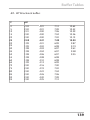
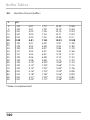
Buffer Tables..........................................................................................133
-U1- Specifiable Buffer Set...................................................................... 143
5
Contents
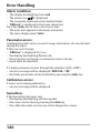
Error Handling.......................................................................................146
Error Messages......................................................................................147
HART: Typical Applications.................................................................150
Sensoface...............................................................................................151
FDA 21 CFR Part 11..............................................................................154
Electronic Signature – Passcodes......................................................... 154
Audit Trail...................................................................................................... 154
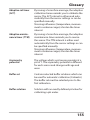
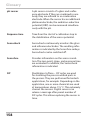
Glossary..................................................................................................155
Index.......................................................................................................160
Trademarks................................................................................................... 171
Passcodes...............................................................................................172
6
Introduction
Intended Use
Stratos Pro A2... PH is used for pH/mV, ORP and temperature
measurement in industry, environment, food processing and sewage
treatment.
Enclosure and mounting possibilities
• The sturdy molded enclosure is rated IP 67/NEMA 4X for outdoor
use. It is made of glass-reinforced PBT / PC and measures
148 mm x 148 mm x 117 mm (H x W x D).
It is provided with knockouts to allow:
• wall mounting (with sealing plugs to seal the enclosure),
see page 14
• post/pipe mounting (Ø 40 … 60 mm, 30 … 45 mm)
see page 15
• panel mounting (138 mm x 138 mm cutout to DIN 43700),
see page 16
Weather protector (accessory)
The weather protector, which is available as accessory, provides
additional protection against direct weather exposure and
mechanical damage, see page 15.
Connection of sensors, cable glands
For connecting the cables, the enclosure provides
• 3 knockouts for cable glands M20x1.5
• 2 knockouts for NPT 1/2” or rigid metallic conduit
For quasi-stationary installations with Memosens sensors, we
recommend using the M12 device socket (accessory ZU 0822) instead
of a cable gland – it allows simple replacement of the sensor cable
without opening the device.
Sensors
The device has been designed for application with commercially
available sensors with a nominal zero point at pH 7, ISFET sensors or
digital sensors. (It can be easily retrofitted for Memosens sensors.)
7
Introduction
Display
Plain-text messages in a large, backlit LC display allow intuitive
operation. You can specify which values are to be displayed in
standard measuring mode ("Main Display", see page 36).
Color-coded user interface
The colored display backlighting signals different operating states
(e.g. alarm: red, HOLD mode: orange, see page 37).
Diagnostics functions
“Sensocheck“ automatically monitors the glass and reference
electrodes; and the “Sensoface“ function clearly indicates the sensor
condition, see page 151.
Data logger
The internal logbook (TAN SW-A002) can handle up to 100 entries –
up to 200 with AuditTrail (TAN SW-A003), see page 117.
2 parameter sets A, B
The device provides two parameter sets which can be switched manually or via a control input for different process adaptations or different
process conditions.
For overview of parameter sets (table for copy), see page 52.
Password protection
Password protection (passcodes) for granting access rights during
operation can be configured, see page 121.
Automatic calibration with Calimatic
You can choose from the most commonly used buffer solutions,
see page 133.
An individual buffer set can also be entered, see page 143.
8
Introduction
Control inputs
Input +
5
Current
Input –
6
HOLD
10
HOLD
HOLD
11
CONTROL
13
CONTROL
CONTROL
14
input
input
input
I input
The analog (0) 4 ... 20 mA current input can
be used for external temperature compensation (TAN required).
See page 82.
HOLD
(floating digital control input)
The HOLD input can be used for external
activation of the HOLD mode, see page 42.
CONTROL
(floating digital control input)
The CONTROL input can be used either for
parameter set selection (A/B) or for flow
monitoring, see page 84.
Signal outputs
The device provides two current outputs (for transmission of
measured value and temperature, for example).
Options
Additional functions can be activated by entering a TAN (page 121).
9
Safety Information
Safety Information
Be sure to read and observe the following instructions!
The device has been manufactured using state of the art technology
and it complies with applicable safety regulations.
When operating the device, certain conditions may nevertheless lead
to danger for the operator or damage to the device.
See also the following documents (page 3):
• "Safety Instructions"
• "Certificates"
CAUTION!
Commissioning must only be performed by trained personnel authorized by the operating company! Whenever it is likely that protection
has been impaired, the device shall be made inoperative and secured
against unintended operation.
The protection is likely to be impaired if, for example:
• the device shows visible damage
• the device fails to perform the intended measurements
• after prolonged storage at temperatures below –30 °C or above
70 °C
• after severe transport stresses
Before recommissioning the device, a professional routine test must
be performed. This test must be carried out at the manufacturer's
factory.
Please note:
Before commissioning you must prove that the device may be
connected with other equipment.
10
Safety Information
Information for installation in hazardous locations
(Stratos Pro A2...X PH)
• Be sure to observe the stipulations of EN 60079-10 / EN 60079-14 or
the corresponding local regulations during installation and commissioning. See also separate “Safety Instructions“ document.
Approvals for application in hazardous locations:
(Stratos Pro A2...X PH)
IECEx, ATEX, FM, CSA, NEPSI, KOSHA and GOST
(see “Certificates“ document).
Memosens Ex wiring
5
124
155
10.6
0
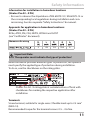
Important Note:
The operator must indicate the type of protection!
When the device provides different types of protection, the operator
must specify the applied type of protection during installation.
To do so, use the checkboxes on the rating plate:
Stratos Pro A2...X rating plate at outside bottom of front with
checkboxes for marking the respective application after
installation
Terminals:
2
Screw terminal, suitable for single wires / flexible leads up to 2.5 mm
(AWG 14).
Recommended torque for the terminal screws: 0.5 ... 0.6 Nm.
11
Overview
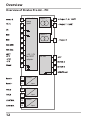
Overview of Stratos Pro A2... PH
A
B
pH / mV /
temp
input
Output 1
8
9
C
Output 2
H
I
17
F
G
D
E
+3 V /–3 V
for ISFET
adapter
RS 485
1
2
K
3
4
12
5
Current
6
10
HOLD
11
13
Control
14
input
input
input
Assembly
Package Contents
Check the shipment for transport damage and completeness!
The package should contain:
• Front unit, rear unit, bag containing small parts
• Specific test report
• Documentation (cf p. 3)
• CD-ROM
1
11
10
2
3
9
8
7 6
5
4
Fig.: Assembling the enclosure
1) Jumper (3 x)
2) Washer (1 x), for conduit
mounting: Place washer
between enclosure and nut
3) Cable tie (3 x)
4) Hinge pin (1 x), insertable
from either side
5) Enclosure screw (4 x)
6) Sealing insert (1 x)
7) Rubber reducer (1 x)
8) Cable gland (3 x)
9) Filler plug (3 x)
10) Hexagon nut (5 x)
11) Sealing plug (2 x), for sealing
in case of wall mounting
13
Assembly
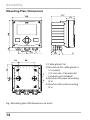
Mounting Plan, Dimensions
117
41
14
148
148
42
6.2
74
34
42
42
1
21
43
80
1)Cable gland (3 x)
2)Knockouts for cable gland or
½” conduit,
21.5 mm dia. (2 knockouts)
3
Conduits not included!
3)Knockout for pipe mounting
4
(4 x)
4)Knockout for wall mounting
(2 x)
Fig.: Mounting plan (All dimensions in mm!)
14
2
Assembly
Pipe Mounting, Protective Hood
ø40...ø60
1
2
3
1)Hose clamp with worm gear
drive to DIN 3017 (2 x)
2)Pipe-mount plate (1 x)
3)For vertical or horizontal posts
or pipes
4)Self-tapping screw (4 x)
4
Fig.: Pipe-mount kit, accessory ZU 0274 (All dimensions in mm!)
147
91
185
199
Fig.: Protective hood for wall and pipe mounting, accessory ZU 0737
(All dimensions in mm!)
15
Assembly
Panel Mounting
< 30
76
31
1)Circumferential sealing (1 x)
2)Screws (4 x)
3)Position of control panel
4)Span piece (4 x)
5)Threaded sleeve (4 x)
Cutout
138 x 138 mm (DIN 43700)
1
1...22
5
4
3
2
Fig.: Panel-mount kit, accessory ZU 0738 (All dimensions in mm!)
16
Installation
Installation Instructions
• Installation of the device must be carried out by trained experts in
accordance with this instruction manual and as per applicable local
and national codes.
• Be sure to observe the technical specifications and input ratings
during installation!
• Be sure not to notch the conductor when stripping the insulation!
• The supplied current must be galvanically isolated. If not, connect
an isolator module.
• All parameters must be set by a system administrator prior to
commissioning!
Terminals:
suitable for single wires / flexible leads up to 2.5 mm2 (AWG 14)
Application in hazardous locations:
For use in hazardous locations, see separate "Certificates" document:
• IECEx
• ATEX
• FM
• CSA
• NEPSI
• GOST
• KOSHA
17
Installation
Rating Plates / Terminal Assignments
Fig.: Terminal assignments of Stratos Pro A2...
Fig.: Stratos Pro A2...N rating plate at outside bottom of front
Fig.: Stratos Pro A2...X rating plate at outside bottom of front
Note: The operator must indicate the type of protection!
When the device provides different types of protection, the operator
must specify the applied type of protection during installation.
To do so, use the checkboxes on the rating plate.
See also “Safety Information“ chapter.
Fig.:
Example of an additional approval plate.
The specifications
refer to the respective
device.
18
Installation
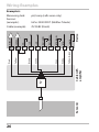
Wiring of Stratos Pro A2... PH
Sensor connection
MK-PH module
Areas for placing the
screwdriver to pull out
the terminals
1
9
10
18
HART
Terminal row 1
Terminal row 2
Fig.: MK-PH module
terminal assignments
In addition:
2 HART pins (between terminal row 1 and 2)
Fig.: Terminals, device opened, back of front unit
19
20
Wiring Examples
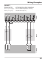
Example 1:
pH, temperature, glass impedance
HA 405-DXK-58 (Mettler-Toledo)
AS9 ZU 0318 (Knick)
Device
Measuring task:
Sensors (example):
Cable (example):
Sensor(s)
Cable
Shield
Core
Jumper!
21
Wiring Examples
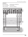
Example 2:
Measuring task:
Sensors (example):
H
I
K
Device
shield
G
RTD
F
RTD (GND)
Core
E
ISM (Data)
Shield
D
ISM (GND)
C
+3 V
SG
B
Sensor(s)
Cable
Shield
ref. el.
A
Core
meas. el
Cable (example):
–3 V
pH/ORP, temp, glass impedance, ref. impedance
pH: HA 405-DXK-58 (Mettler-Toledo),
Pt: ZU 0073 (Knick)
2x AS9 ZU 0318 (Knick)
22
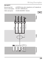
Wiring Examples
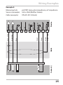
Example 3:
K
Cable
Sensor(s)
White
Jumper!
Device
shield
I
Shield
Yellow/Green
H
RTD
G
RTD (GND)
F
ISM (Data)
ISM (GND)
E
Green
Core
D
–3 V
SG
C
pH, temp, glass impedance
SE 533 (Knick)
VP6 ZU 0313 (Knick)
+3 V
ref. el.
B
Shield Red
A
Clear
meas. el
Measuring task:
Sensors (example):
Cable (example):
23
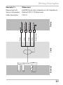
Wiring Examples
Example 4:
I
K
Sensor(s)
Cable
White
Green
Core
Shield
Device
shield
H
Shield
Yellow/Green
G
RTD
F
RTD (GND)
E
ISM (Data)
ISM (GND)
D
–3 V
SG
C
+3 V
ref. el.
B
Shield Red
A
Core Clear
meas. el
Measuring task:
pH/ORP, temp, glass impedance, ref. impedance
Sensors (example): pH: SE 533 (Knick)
Pt: ZU 0073 (Knick)
Cable (example):
VP6 ZU 0313 (Knick) or AS9 ZU 0318 (Knick)
24
Wiring Examples
Example 5:
K
Device
shield
I
Sensor(s)
Cable
Shield
Yellow/Green
RTD
H
White
G
RTD (GND)
F
Green
Blue
E
ISM (Data)
Shield Red
D
ISM (GND)
C
–3 V
SG
B
pH/ORP, temp, glass impedance, ref. impedance
InPro 4260 (Mettler-Toledo)
VP6 ZU 0313 (Knick)
+3 V
ref. el.
A
Core Clear
meas. el
Measuring task:
Sensors (example):
Cable (example):
25
Wiring Examples
Example 6:
H
I
K
Sensor(s)
Cable with
amplifier
White
Gray
Green
Brown
Yellow
Pink
Jumper!
Device
shield
G
Yellow/Green
F
RTD (GND)
E
RTD
D
ISM (Data)
C
ISM (GND)
SG
B
InPro 3300 ISFET (Mettler-Toledo)
ZU 0582 (Knick)
–3 V
ref. el.
A
pH, temp (safe areas only)
+3 V
meas. el
Measuring task:
Sensors
(example):
Cable (example):
26
Wiring Examples
Example 7:
Sensor(s)
Cable
Core
Shield
Device
Caution!
Do not connect an additional analog sensor!
Measuring task:
pH/ORP, temp, glass impedance, ref. impedance
Sensors (example): ISM digital InPro 4260i (Mettler-Toledo)
Cable (example):
AK9 (Mettler-Toledo)
27
Wiring Examples
Example 8 – Note: Switch off Sensocheck!
Device
Measuring task:
ORP, temp, glass impedance, ref. impedance
Sensors (example): ORP: SE 535 (Knick)
Cable (example):
AS9 ZU 0318 (Knick)
Sensor(s)
Cable
Shield
Core
Shield
Jumper!
28
Wiring Examples
Example 9:
Measuring task:
Sensors (example):
Cable (example):
pH/ORP, temp, glass impedance, ref. impedance
SE 533/1-ADIN (Knick)
CA/003-NAADIN11 (Knick)
Con
Device
Indu
Sensor(s)
Cable
Shield (blue)
4
White/Clear
3
Yellow
2
Green
Brown
1
29
Wiring Examples
Example 10:
I
K
Pfaudler probe
Cable
H
Device
shield
G
RTD
F
RTD (GND)
E
D
ISM (Data)
C
ISM (GND)
SG
B
–3 V
ref. el.
A
+3 V
meas. el
Connecting a Pfaudler probe:
30
Device
pH Reiner
with equipotential bonding,
VP screw cap
Differential
Models 03/04
Models 18/40
with equipotenwith equipoten- tial bonding
tial bonding
Models 03/04
without equi
potential
bonding
A
Coax core
Coax WH
Coax WH
meas
Coax WH
B
ref
Coax shield
Coax BN
Coax BN
Coax BN
C
SG
Blue
Blue
Blue
Jumper B/C
H
RTD
(GND)
Green
Brown
Brown
Brown
I
RTD
White
Green, Black
Green, Black
Green, Black
K
Shield
Green/Yellow, Gray Orange, Violet
Orange, Violet
Orange, Violet
D
E
F
G
Wiring Examples
Sensor(s)
Cable
Shield (clear)
4
White
3
Yellow
2
Green
Brown
1
Device
pH/ORP, temp, glass impedance, ref. impedance
Orbisint CPS 11 D Memosens
CYK 10
GND/shield
Measuring task:
Sensors (example):
Cable (example):
RS 485 (B)
Memosens
RS 485 (A)
Example 11:
31
User Interface, Keypad
1
MEMO
SENS
2
3
4
Key
Function
•
•
•
•
•
•
•
Arrow keys
up / down
Arrow keys
left / right
32
1 IrDA transmitter/receiver
2 Display
3 Keypad
4 Rating plate
(enclosure bottom)
•
•
•
•
•
Return to last menu level
Directly to measuring mode (press > 2 s)
Measuring mode: other display
Retrieve information
Show error messages
Configuration: Confirm entries,
next configuration step
Calibration:
Continue program flow
Measuring mode: Call menu
Menu: Increase/decrease a numeral
Menu: Selection
Previous/next menu group
Number entry: Move between digits
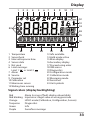
Display
1
2
3
4
5
6
7
8
9
10
11
MEMO
SENS
23
12
13
14
24
15
16
22
21
1 Temperature
2 Sensocheck
3 Interval/response time
4 Sensor data
5 Not used
6 Limit message:
Limit 1
or Limit 2
7 Alarm
8 Service
9 Parameter set
10Calibration
11Memosens sensor
12Waiting time running
20
19
18
17
13Info available
14Hold mode active
15Main display
16Secondary display
17Proceed using enter
18ISM sensor
19Diagnostics
20Configuration mode
21Calibration mode
22Measuring mode
23Sensoface
24Unit symbols
Signal colors (display backlighting)
Red
Red blinking
Orange
Turquoise
Green
Purple
Alarm (in case of fault: display values blink)
Input error: illegal value or wrong passcode
HOLD mode (Calibration, Configuration, Service)
Diagnostics
Info
Sensoface message
33
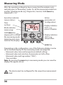
Measuring Mode
After the operating voltage has been connected, the analyzer automatically goes to “Measuring“ mode. To call the measuring mode from
another operating mode (e.g. Diagnostics, Service): Hold meas key
depressed (> 2 s).
Sensoface indicator
(sensor status)
Time
(or flow)
Mode indicator
(measuring)
Hold meas key
depressed for calling
the measuring mode
(pressing once more
switches the display)
Active
parameter set
(configuration)
Display indicates
OUT1: e.g.
process variable
Display indicates
OUT2: e.g.
temperature
enter key
Depending on the configuration, one of the following displays can be
set as standard display for the measuring mode (see page 36):
• Measured value, time and temperature (default setting)
• Measured value and selection of parameter set A/B or flow
Measured value and tag number (“TAG”)
• Time and date
Note: By pressing the meas key in measuring mode you can view the
displays for approx. 60 sec.
The device must be configured for the respective measurement
task!
34
Selecting the Mode / Entering Values
To select the operating mode:
1)Hold meas key depressed (> 2 s) (directly to measuring mode)
2)Press menu key: the selection menu appears
3)Select operating mode using left / right arrow key
4)Press enter to confirm the selected mode
Selection menu
Selected mode
(blinks)
4
1
3
2
To enter a value:
5)Select numeral: left / right arrow key
6)Change numeral: up / down arrow key
7)Confirm entry by pressing enter
5
7
6
35
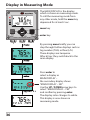
Display in Measuring Mode
The MAIN DISPLAY is the display
which is shown in measuring mode.
To call the measuring mode from
any other mode, hold the meas key
depressed for at least 2 sec.
meas key
enter key
By pressing meas briefly you can
step through further displays such as
tag number (TAG) or flow (L/h).
These displays are turquoise.
After 60 sec they switch back to the
main display.
approx. 2 s
36
Press enter to
select a display as
MAIN DISPLAY –
the secondary display shows
"MAIN DISPLAY – NO“.
Use the UP / DOWN arrow keys to
select "MAIN DISPLAY – YES“
and confirm by pressing enter.
The display color changes to white.
This display is now shown in
measuring mode.
Color-Coded User Interface
The color-coded user interface guarantees increased operating safety.
Operating modes are clearly signaled.
The normal measuring mode is white. Information text appears on a
green screen and the diagnostic menu appears on turquoise.
The orange HOLD mode (e.g. during calibration) is quickly visible as is
the magenta screen which indicates asset management messages for
predictive diagnostics – such as maintenance request, pre-alarm and
sensor wear.
The alarm status has a particularly noticeable red display color and is
also signaled by flashing display values. Invalid inputs or false passcodes cause the entire display to blink red so that operating errors are
noticeably reduced.
White:
Measuring mode
Red blinking:
Alarm, errors
Turquoise:
Magenta:
Maintenance request Diagnostics
Orange:
HOLD mode
Green:
Information texts
37
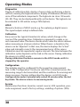
Operating Modes
Diagnostics
Display of calibration data, display of sensor data, performing a device
self-test, viewing the logbook entries, display of hardware/software versions of the individual components. The logbook can store 100 events
(00...99). They can be displayed directly on the device. The logbook can
be extended to 200 entries using a TAN (Option).
HOLD
Manual activation of HOLD mode, e.g. for replacing a digital sensor.
The signal outputs adopt a defined state.
Calibration
Every sensor has typical characteristic values, which change in the
course of the operating time. Calibration is required to supply a correct measured value. The device checks which value the sensor delivers
when measuring in a known solution. When there is a deviation, the
device can be “adjusted“. In that case, the device displays the “actual“
value and internally corrects the measurement error of the sensor.
Calibration must be repeated at regular intervals. The time between the
calibration cycles depends on the load on the sensor. During calibration
the device is in HOLD mode.
During calibration the device remains in the HOLD mode until it is
stopped by the operator.
Configuration
The analyzer must be configured for the respective measurement
task. In the “Configuration“ mode you select the connected sensor, the
measuring range to be transmitted, and the conditions for warning and
alarm messages. During configuration the device is in HOLD mode.
Configuration mode is automatically exited 20 minutes after the last
keystroke. The device returns to measuring mode.
Service
Maintenance functions (monitor, current source), IrDA operation, passcode assignment, reset to factory settings, enabling of options (TAN).
38
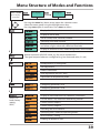
Menu Structure of Modes and Functions
Meas. mode
(main display
selectable)
TAG display
CLK display
after 60 s
after 60 s
Pressing the menu key (down arrow) opens the selection menu.
Select the menu group using the left/right arrow keys.
Pressing enter opens a menu item. Press meas to return.
Display of calibration data
Display of sensor data
Self test: RAM, ROM, EEPROM, module
100 events with date and time
Display of measured values (mV_pH, mV_ORP, RTD,
resistances of glass electrode, reference electrode)
Display of software version, model designation, serial number
Manual activation of HOLD mode, e.g. for sensor replacement.
The signal outputs behave as configured (e.g. last measured value, 21 mA)
pH adjustment (as configured)
ORP adjustment
Product calibration
Zero adjustment (for ISFET only)
Adjustment of temperature probe
Configuring parameter set A
Configuring parameter set B
Display of measured values for validation (simulators)
(Access via
code, factory
setting:
5555)
For ISM: Reset TTM, increment autoclaving counter
Current source, output 1
Current source, output 2
Activating the IrDA interface
Specifying access codes for operating modes
Reset to factory setting
Enabling an option via TAN
39
40
HOLD Mode
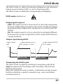
The HOLD mode is a safety state during configuration and calibration.
Output current is frozen (LAST) or set to a fixed value (FIX).
The HOLD mode is indicated by orange display backlighting.
HOLD mode, display icon:
Output signal response
• LAST: The output current is frozen at its last value. Recommended
for short configuration procedures. The process should not change
decisively during configuration. Changes are not noticed with this
setting!
• FIX: The output current is set to a value that is noticeably different
from the process value to signal the control system that the device
is being worked at.
Output signal during HOLD:
Output current
[mA]
Output signal for HOLD
FIX setting = 21.0 mA
Output signal for HOLD
LAST setting
21
4
HOLD active
HOLD active
Terminating the HOLD mode
The HOLD mode is ended by switching to measuring mode (hold
meas key depressed). The display reads “Good Bye“, after that, the
HOLD mode is exited.
When the calibration mode is exited, a confirmation prompt ensures
that the installation is ready for operation (e.g.: sensor reinstalled,
located in process).
41
Alarm
External activation of HOLD
The HOLD mode can be activated from outside by sending a signal to
the HOLD input (e.g. from the process control system).
Power supply
12...24 V AC/DC
HOLD
10
11
input
Process control system
HOLD inactive
HOLD active
0...2 V AC/DC
10...30 V AC/DC
Manual activation of HOLD
The HOLD mode can be activated manually from the HOLD menu. This
allows checking or replacing a sensor, for example, without provoking
unintended reactions at the outputs.
Press meas key to return to selection menu.
Alarm
When an error has occurred, Err xx is displayed immediately.
Only after expiry of a user-defined delay time will the alarm be
registered and entered in the logbook.
During an alarm the display blinks, the display backlighting turns red.
Error messages can also be signaled by a 22 mA output current
(see Configuration).
2 sec after the failure event is corrected, the alarm status will be
deleted.
42
Alarm and HOLD Messages
Message
Alarm
(22 mA)
Released by
Sensocheck
Error Messages
Cause
Polarization / Cable
Flow (CONTROL input)
HOLD via menu or input
Configuration
Calibration
Service
Generating a message via the CONTROL input
(min. flow / max. flow)
The CONTROL input can be used for parameter set selection or for
flow measurement (pulse principle), depending on its assignment in
the “Configuration” menu.
When preset to flow measurement
an alarm can be generated when the measured flow exceeds a
specified range:
(specify value, default: 5 liters/h)
(specify value, default: 25 liters/h)
CONTROL
Power supply
12...24 V AC/DC
13
14
input
43
Configuration
Menu Structure of Configuration
The device provides 2 parameter sets “A“ and “B“. By switching between the parameter sets you can adapt the device to different measurement situations, for example.
Parameter set “B“ only permits setting of process-related parameters.
The configuration steps are assigned to different menu groups.
With the left/right arrow keys you can jump between the individual menu groups.
Each menu group contains menu items for setting the parameters.
Pressing enter opens a menu item. Use the arrow keys to edit a value.
Press enter to confirm/save the settings.
Return to measurement: Hold meas key depressed (> 2 s).
Select menu
group
Menu group
Code
Display
Select menu
item
Sensor selection
Menu item 1
...
Menu item ...
Current output 1
Current output 2
Compensation
Control input
(parameter set or flow
measurement)
Alarm mode
Setting the clock
Tag number
44
Configuration
Parameter set A/B: configurable menu groups
The device provides 2 parameter sets “A“ and “B“. By switching between the parameter sets you can adapt the device to different measurement situations, for example.
Parameter set “B“ only permits setting of process-related parameters.
Menu group
Parameter set A
Parameter set B
Sensor selection
Current output 1
Current output 2
Compensation
Control input
Alarm mode
Parameter set
selection
Setting the clock
Tag number
--Current output 1
Current output 2
Compensation
--Alarm mode
-------
External switchover of parameter sets A/B
You can switch between parameter sets A and B by applying a signal
).
to the CONTROL input (parameter setting:
Max. 30 V AC/DC
CONTROL
13
14
input
Stratos Pro A2...
e.g. process control system
Parameter set A active
Parameter set B active
0...2 V AC/DC
10...30 V AC/DC
45
Configuration
Manual switchover of parameter sets A/B
Display
Action
Remark
To switch between
parameter sets:
Press meas.
Manual selection of
parameter sets must have
been preset in CONFIG
mode. Default setting is a
fixed parameter set A.
Wrong settings change
the measurement
properties!
PARSET blinks in the
lower line.
Select parameter set
using and keys
Select
PARSET A / PARSET B
Press enter to
confirm.
Cancel by pressing
meas.
46
Configuration
Configuration
Select
Default
Sensor (SENSOR)
(omitted for ISM)
(EXT. only with I-input
enabled via TAN)
(EXT. only with I-input
enabled via TAN)
Note: Pressing info
displays nominal buffer
values + manufacturer
U1
(For specifiable
buffer set,
see Appendix:
“Buffer Tables“)
Enter values for buffer 1
Enter values for buffer 2
(omitted for ISM)
*) The setting: TEMP MEAS: AUTO/MAN/EXT applies to all outputs: OUT1/OUT2/display;
Sensors with deviating zero/slope require the “Pfaudler” option (TAN).
Settings with “Sensor: STANDARD” selected (not required for Memosens Pfaudler sensor).
**) only with STANDARD and Pfaudler option (TAN), not with Memosens Pfaudler.
47
Configuration
Configuration
Select
Default
Sensor (SENSOR)
ISM
(for
ISM sensors only)
Output 1 (OUT1)
Select °C / °F at
“Sensor“
48
Configuration
Configuration
Select
Default
Output 2 (OUT2)
Select °C / °F at
“Sensor“
Temperature compensation (CORRECTION)
0 ... 100 °C
in 5°C steps
49
Configuration
Configuration
Control input (CNTR_IN)
Select
Default
Parameter-set
switchover (PARSET)
or
flow measurement
(FLOW)
12000
pulses/liter
0 ... 20000
pulses/liter
Alarm (ALARM)
Real-time clock (CLOCK)
Tag number (TAG)
(Input in text line)
___
*) is only displayed if enabled and SENSOR: TEMP EXT has been selected.
**)Hysteresis fixed at 5% of threshold value
50
Configuration
Support of Pfaudler Sensors
or pH sensors with a zero point other than pH 7 and/or deviating slope,
e.g. pH sensors with a zero point at pH 4.6
This requires an additional function (TAN). The option is enabled in the
SERVICE / OPT: PFAUDLER menu (see page 121).
For Pfaudler standard pH sensors, you can specify a nominal zero point and a
nominal slope.
In addition, you can enter a pHiso value.
The additional entries appear in the CONFIGURATION / SENSOR menu:
SNS: NOM ZERO (default: 07.00 pH)
SNS: NOM SLOPE (default: 59.2 mV)
SNS: PH_ISO (default: 07.00 pH)
Prior to measurement, you must enter the values for nominal zero and slope and
the isothermal intersection point pHiso as provided by the manufacturer and
perform a calibration using suitable buffer solutions.
When you use a Memosens Pfaudler sensor, the data will be read from the sensor or
will be set to standard values. Here, you do not have to make entries. The respective
menu items will be suppressed.
The nominal ZERO/SLOPE values are required for the proper functioning of the
sensor monitoring and calibration functions (Sensoface, Calimatic), they do not
replace an adjustment (calibration)!
Typical values
Probe
Pfaudler
enamel probes
(Pfaudler
specifications)
Probes with
absolute pH
measurement
and Ag/AgCl
reference system
Differential pH
Probes with
probe
absolute pH
measurement
and Ag/A (silver
acetate) reference
system
Nom. slope
55 mV/pH
55 mV/pH
55 mV/pH
55 mV/pH
Nom. zero
pHiso
pH 8.65
pH 1.35
pH 8.65
pH 1.35
pH 1.35
pH 1.35
pH 7 ... 12
pH 3.00
Please note:
Please refer to the operating instructions of the respective sensor for more
information on functioning, installation, calibration and configuration.
51
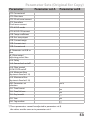
Parameter Sets (Original for Copy)
Parameter
Parameter set A
Parameter set B
SNS: Sensor type
SNS: RTD type
SNS: Temperature unit
SNS: Temp measurement
SNS: Manual meas. temp
SNS: Calibration temp
SNS: Manual cal temp
SNS: Calibration mode
SNS: Select buffer set
(-U1-, see Appendix)
SNS: Calibration timer
SNS: Calibration cycle
SNS: ISM adaptive cal
timer (ACT)
SNS: ISM adaptive
maintenance timer (TTM)
SNS: CIP counter
SNS: CIP cycles
SNS: SIP counter
SNS: SIP cycles
SNS: Autoclaving counter
OT1: Process variable
OT1: Current start
OT1: Current end
OT1: Filter time
OT1: 22 mA error current
OT1: Sensoface
22mA error current
OT1: HOLD mode
OT1: HOLD-FIX current
OT2: Process variable
OT2: Current start
52
*) These parameters cannot be adjusted in parameter set B,
the values are the same as in parameter set A.
Parameter Sets (Original for Copy)
Parameter
Parameter set A
Parameter set B
OT2: Current end
OT2: Filter time
OT2: 22 mA error current
OT2: Sensoface
22mA error current
OT2: HOLD mode
OT2: HOLD-FIX current
COR: Temp coefficient
COR: Ext. temp input
COR: Current range
COR: Current start
COR: Current end
IN: Parameter set A/B or
flow
IN: (Flow meter)
Adjusting pulses/liter
ALA: Delay
ALA: Sensocheck on/off
ALA: Flow control
FLOW CNTR on/off
ALA: Minimum flow
(hysteresis fixed at 5 %)
ALA: Maximum flow
(hysteresis fixed at 5 %)
PAR: Parameter set
selection
CLK: Time format
CLK: Time hh/mm
CLK: Day/month
CLK: Year
TAG: Tag number
*) These parameters cannot be adjusted in parameter set B,
the values are the same as in parameter set A.
53
Configuration
Sensor
Select: sensor type, temperature probe, temperature unit,
temp detection during measurement
1) Press menu key.
2) Select CONF using keys, press enter.
3) Select parameter set using , press enter.
4) Select SENSOR menu using keys, press
enter.
5) All items of this menu group are indicated by
the “SNS:” code.
Press enter to select menu,
edit using arrow keys (see next page).
Confirm (and proceed) by pressing enter.
6) Exit: Press meas key until the [meas] mode
indicator is displayed.
Select sensor type
Select type of temp probe
Temperature unit
Temp detection during measurement
(Manual temperature)
Temp detection during calibration
(Manual temperature)
Calibration mode
(Auto: Buffer set)
Calibration timer
Calibration cycle
Cleaning cycles
Cleaning cycle counter
Sterilization cycles
Sterilization cycle counter
54
Configuration
5
Menu item
Action
Select sensor type
Select sensor type using
keys.
Choices
Digital sensors:
Press enter to confirm.
Select type of temp
probe
(not for digital sensors)
Select type of temperature probe using
keys.
Press enter to confirm.
Temperature unit
Select °C or °F using
keys.
Press enter to confirm.
Select mode using
Temp detection
during measurement keys:
AUTO: Measured by
sensor
MAN: Direct input of
temperature, no measurement (see next step)
EXT: Temperature specified via current input
(only if TAN E enabled)
Press enter to confirm.
(Manual temperature) Modify digit using
keys,
select next digit using
keys.
Press enter to confirm.
55
Configuration
Sensor
Select: temp detection during calibration, calibration mode
1) Press menu key.
2) Select CONF using keys, press enter.
3) Select parameter set using , press enter.
4) Select SENSOR menu using keys, press
enter.
5) All items of this menu group are indicated by
the “SNS:” code.
Press enter to select menu,
edit using arrow keys (see next page).
Confirm (and proceed) by pressing enter.
6) Exit: Press meas key until the [meas] mode
indicator is displayed.
Select sensor type
Select type of temp probe
Temperature unit
Temp detection during measurement
(Manual temperature)
Temp detection during calibration
5
(Manual temperature)
Calibration mode
(Auto: Buffer set)
Calibration timer
Calibration cycle
Cleaning cycles
6
Cleaning cycle counter
Sterilization cycles
Sterilization cycle counter
56
Configuration
5
Menu item
Action
Temp detection
during calibration
Select mode using
keys:
AUTO: Measured by
sensor
MAN: Direct input of
temperature, no measurement (see next step)
EXT: Temperature specified via current input
(only if TAN E enabled)
Press enter to confirm.
Choices
(Manual temperature) Modify digit using
keys,
select next digit using
keys.
Press enter to confirm.
Calibration mode
Select CALMODE using
keys:
AUTO: Calibration with
Calimatic buffer set
recognition
MAN: Manual entry of
buffer solutions
DAT: Input of adjustment
data of premeasured
sensors
Press enter to confirm.
(Auto: Buffer set)
Select buffer set using
keys (see buffer tables for nominal
values).
Press enter to confirm.
-00-...-10-,
(-U1-, see Appendix)
Pressing the info key displays the manufacturer
and nominal values in the
lower line.
57
Configuration
Sensor
Adjust: Cal timer, cal cycle
1) Press menu key.
2) Select CONF using keys, press enter.
3) Select parameter set using , press enter.
4) Select SENSOR menu using keys, press
enter.
5) All items of this menu group are indicated by
the “SNS:” code.
Press enter to select menu,
edit using arrow keys (see next page).
Confirm (and proceed) by pressing enter.
6) Exit: Press meas key until the [meas] mode
indicator is displayed.
Select sensor type
Select type of temp probe
Temperature unit
Temp detection during measurement
(Manual temperature)
Temp detection during calibration
5
(Manual temperature)
Calibration mode
(Auto: Buffer set)
Calibration timer
Calibration cycle
Cleaning cycles
6
Cleaning cycle counter
Sterilization cycles
Sterilization cycle counter
58
Configuration
5
Menu item
Action
Calibration timer
Adjust CALTIMER using
keys:
OFF: No timer
ADAPT: Maximum cal
cycle (adjust in the next
step)
FIX: Fixed cal cycle (adjust
in the next step)
Press enter to confirm.
Calibration cycle
Choices
With ADAPT, the calibration cycle is automatically
reduced depending on
the sensor load (high
temperatures and pH
values) and for digital
sensors also depending
on the sensor wear
Only with FIX/ADAPT:
Modify digit using
keys,
select next digit using
keys.
Press enter to confirm.
Note for the calibration timer:
When Sensocheck has been activated in the Configuration – Alarm
menu, the expiration of the calibration interval is indicated by
Sensoface:
Display
Status
+
Over 80 % of the calibration interval has
already past.
+
The calibration interval has been exceeded.
The calibration timer settings apply to both parameter sets A and B.
The time remaining until the next due calibration can be seen in the
diagnostics menu (see Diagnostics chapter).
59
Configuration
ISM Sensor
Adaptive cal timer (ACT)
1
2
enter
3
enter
1) Press menu key.
2) Select CONF using keys,
press enter.
3) Select parameter set using keys,
press enter.
4) Select SENSOR menu using keys,
press enter.
5) All items of this menu group are indicated by
the “SNS:” code.
Press enter to select menu,
edit using arrow keys (see next page).
Confirm (and proceed) by pressing enter.
6) Exit: Press meas key until the [meas] mode
indicator is displayed.
Select sensor type
Temperature unit
4
Temp detection during measurement
(Manual temperature)
Temp detection during calibration
enter
(Manual temperature)
Calibration mode
5
(Auto: Buffer set)
ACT - Adaptive calibration timer
TTM - Adaptive maintenance timer
meas
6
60
CIP/SIP cycles
Autoclaving counter
Configuration
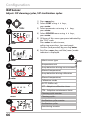
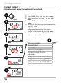
Adaptive Calibration Timer (ACT)
By issuing a Sensoface message, the adaptive calibration timer
reminds you to calibrate the sensor. After expiration of the ACT interval, Sensoface is getting “sad”. Pressing the info key shows the text
“OUT OF CAL TIME CALIBRATE SENSOR” which reminds you that a
calibration is due. The ACT interval is either read automatically from
the sensor settings or can be specified manually (max. 9999 days).
Stressing influences (temperature, measurement in extreme ranges)
shorten the timer interval.
The adaptive cal timer is reset after each calibration.
You can configure the current outputs so that a Sensoface message
generates a 22-mA error signal, see page 75.
Menu item
Action
Adaptive cal timer
(ACT)
Select using keys:
AUTO:
The interval stored in
the ISM sensor is used
(default)
MAN:
The interval is specified
manually (0 ... 9999 days)
Choices
Press enter to confirm.
61
Configuration
ISM Sensor
Adaptive Maintenance Timer (TTM)
1
2
enter
3
enter
1) Press menu key.
2) Select CONF using keys,
press enter.
3) Select parameter set using keys,
press enter.
4) Select SENSOR menu using keys,
press enter.
5) All items of this menu group are indicated by
the “SNS:” code.
Press enter to select menu,
edit using arrow keys (see next page).
Confirm (and proceed) by pressing enter.
6) Exit: Press meas key until the [meas] mode
indicator is displayed.
Select sensor type
Temperature unit
4
Temp detection during measurement
(Manual temperature)
Temp detection during calibration
enter
(Manual temperature)
Calibration mode
5
(Auto: Buffer set)
ACT - Adaptive calibration timer
TTM - Adaptive maintenance timer
meas
6
62
CIP/SIP cycles
Autoclaving counter
Configuration
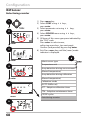
Adaptive Maintenance Timer
(TTM, Time To Maintenance)
By issuing a Sensoface message, the adaptive maintenance timer
reminds you to service the sensor. After expiration of the interval,
Sensoface is getting “sad”. Pressing the info key shows the text
“OUT OF MAINTENANCE CLEAN SENSOR” which reminds you
that a sensor maintenance is due. The TTM interval is either read
automatically from the sensor settings or can be specified manually
(max. 9999 days).
Stressing influences (temperature, measurement in extreme ranges)
shorten the timer interval.
You can configure the current outputs so that a Sensoface message
generates a 22-mA error signal, see page 75.
Menu item
Action
Adaptive maintenance timer (TTM)
Select using keys:
AUTO:
The interval stored in
the ISM sensor is used
(default)
MAN:
The interval is specified
manually (0 ... 9999 days)
Choices
Press enter to confirm.
The adaptive maintenance timer can be reset in the SERVICE /
SENSOR / TTM menu. Here, the interval is reset to its initial value.
To do so, select
“TTM RESET = YES“
and confirm by pressing
enter.
63
Configuration
Standard and ISFET Sensor
Adjust: CIP cleaning cycles, SIP sterilization cycles
1
2
enter
3
1) Press menu key.
2) Select CONF using keys,
press enter.
3) Select parameter set using keys,
press enter.
4) Select SENSOR menu using keys,
press enter.
5) All items of this menu group are indicated by
the “SNS:” code.
Press enter to select menu,
edit using arrow keys (see next page).
Confirm (and proceed) by pressing enter.
6) Exit: Press meas key until the [meas] mode
indicator is displayed.
5
enter
Select sensor type
Select type of temp probe
4
Temperature unit
Temp detection during measurement
(Man. temperature)
enter
Temp detection during calibration
(Man. temperature)
5
Calibration mode
(Auto: Buffer set)
Calibration timer
meas
6
64
Calibration cycle
CIP cleaning cycles
SIP sterilization cycles
enter
Configuration
5
Menu item
Action
Choices
CIP / SIP
The following adjustments are possible for standard and ISFET
sensors:
Select ON or OFF using
Cleaning cycles
keys.
When switched on, the
cycles will be entered in
the extended logbook
but not counted.
Press enter to confirm.
Sterilization cycles
Select ON or OFF using
keys.
When switched on, the
cycles will be entered in
the extended logbook
but not counted.
Press enter to confirm.
Logging the cleaning and sterilization cycles with connected sensor
helps measuring the load on the sensor.
Suitable for biochemical applications (process temp approx. 0 ... 50 °C,
CIP temp > 55 °C, SIP temp > 115 °C).
65
Configuration
ISM Sensor
Adjust: CIP cleaning cycles, SIP sterilization cycles
1
2
enter
3
enter
1) Press menu key.
2) Select CONF using keys,
press enter.
3) Select parameter set using keys,
press enter.
4) Select SENSOR menu using keys,
press enter.
5) All items of this menu group are indicated by
the “SNS:” code.
Press enter to select menu,
edit using arrow keys (see next page).
Confirm (and proceed) by pressing enter.
6) Exit: Press meas key until the [meas] mode
indicator is displayed.
Select sensor type
Temperature unit
4
Temp detection during measurement
(Manual temperature)
Temp detection during calibration
enter
5
(Manual temperature)
Calibration mode
(Auto: Buffer set)
ACT - Adaptive calibration timer
TTM - Adaptive maintenance timer
Cleaning cycle counter
meas
6
Cleaning cycles
Sterilization cycle counter
Sterilization cycles
Autoclaving counter
66
Configuration
5
Menu item
Action
Choices
CIP / SIP
The following adjustments are possible for ISM sensors :
Select ON or OFF using
ON/OFF
Cleaning cycle
keys.
counter
Press enter to confirm.
Cleaning cycles
Only with CIP COUNT ON: 0...9999 CYC
Enter value using
(0000 CYC)
keys.
Press enter to confirm.
Sterilization cycle
counter
Select ON or OFF using
keys.
ON/OFF
Press enter to confirm.
Sterilization cycles
Only with CIP COUNT ON: 0...9999 CYC
Enter value using
(0000 CYC)
keys.
Press enter to confirm.
The cleaning and sterilization cycles are counted to measure the load
on the sensor.
Suitable for biochemical applications (process temp approx. 0...50 °C,
CIP temperature > 55 °C, SIP temperature > 115 °C).
67
Configuration
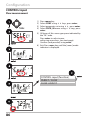
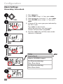
ISM Sensor
Autoclaving counter
1
2
enter
3
enter
1) Press menu key.
2) Select CONF using keys,
press enter.
3) Select parameter set using keys,
press enter.
4) Select SENSOR menu using keys,
press enter.
5) All items of this menu group are indicated by
the “SNS:” code.
Press enter to select menu,
edit using arrow keys (see next page).
Confirm (and proceed) by pressing enter.
6) Exit: Press meas key until the [meas] mode
indicator is displayed.
Select sensor type
Temperature unit
4
Temp detection during measurement
(Manual temperature)
Temp detection during calibration
enter
(Manual temperature)
Calibration mode
5
(Auto: Buffer set)
ACT - Adaptive calibration timer
TTM - Adaptive maintenance timer
meas
6
68
CIP/SIP cycles
Autoclaving counter
Configuration
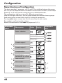
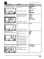
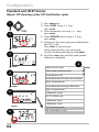
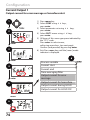
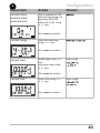
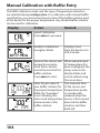
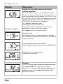
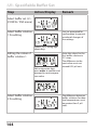
Autoclaving Counter
After reaching a specified limit value the autoclaving counter generates a Sensoface message. As soon as the counter has reached
the specified value, Sensoface is getting “sad”. Pressing the info key
shows the text “AUTOCLAVE CYCLES OVERRUN” which reminds you
that the maximum number of autoclaving cycles has been reached.
After each autoclaving process, you must manually increment the
autoclaving counter in the SENSOR service menu on the transmitter.
The transmitter displays “INCREMENT AUTOCLAVE CYCLE” as confirmation. You can configure the current outputs so that a Sensoface
message generates a 22-mA error signal, see page 75.
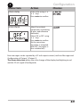
Menu item
Action
Choices
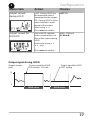
Autoclaving counter Select using keys:
ON:
The cycles are specified
manually (0 ... 9999)
Press enter to confirm.
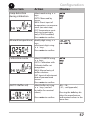
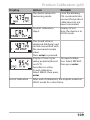
With the autoclaving counter switched on, you must increment the
count after each autoclaving process in the SERVICE menu SENSOR/
AUTOCLAVE :
After having completed
Incrementing the
autoclaving counter an autoclaving process,
open the SERVICE menu
(SERVICE menu)
SENSOR / AUTOCLAVE to
increment the autoclaving count.
To do so, select “YES”
and confirm by pressing
enter.
69
Configuration
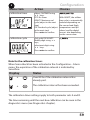
Current Output 1
Output current range. Current start. Current end.
1) Press menu key.
2) Select CONF using keys, press enter.
3) Select parameter set using keys, press
enter.
4) Select OUT1 menu using keys, press
enter.
5) All items of this menu group are indicated by
the “OT1:” code.
Press enter to select menu,
edit using arrow keys (see next page).
Confirm (and proceed) by pressing enter.
6) Exit: Press meas key until the [meas] mode
indicator is displayed.
5
6
70
Process variable
Current start
Current end
Time averaging filter
Output current for error
message
Output current for Sensoface
Output current during HOLD
Output current for HOLD FIX
Configuration
5
Menu item
Action
Choices
Process variable
Select using keys:
PH: pH value
ORP: Redox potential
TMP: Temperature
Press enter to confirm.
Current start
Modify digit using
keys,
select next digit using
keys.
Press enter to confirm.
Current end
Enter value using
keys.
Press enter to confirm.
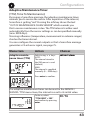
Assignment of measured values: Current start and current end
Example 2: Range pH 5...7
Advantage: Higher resolution in
range of interest
[pH]
Example 1: Range pH 0...14
[pH]
14
7
7
5
0
Output current
4
20 [mA]
Output current
5
4
20 [mA]
71
Configuration
Current Output 1
Adjusting the time interval of the output filter
1) Press menu key.
2) Select CONF using keys, press enter.
3) Select parameter set using keys, press
enter.
4) Select OUT1 menu using keys, press
enter.
5) All items of this menu group are indicated by
the “OT1:” code.
Press enter to select menu,
edit using arrow keys (see next page).
Confirm (and proceed) by pressing enter.
6) Exit: Press meas key until the [meas] mode
indicator is displayed.
5
5
6
72
Process variable
Current start
Current end
Time averaging filter
Output current during error
message
Output current for Sensoface
Output current during HOLD
Output current for HOLD FIX
enter
Configuration
5
Menu item
Action
Time averaging filter
Enter value using
keys.
Choices
Press enter to confirm.
Time averaging filter
To smoothen the current output, a low-pass filter with adjustable filter
time constant can be switched on. When there is a jump at the input
(100 %), the output level is at 63 % after the time interval has been
reached. The time interval can be set from 0 to 120 sec. If the time
interval is set to 0 sec, the current output directly follows the input.
Please note:
The filter only acts on the current output, not on the display or the
limit value!
During HOLD the filter is not applied. This prevents a jump at the
output.
Display
pH
0/4-20 mA
Time interval 0...120 s
Temp
Time interval 0...120 s
73
Configuration
Current Output 1
Output current for error message or Sensoface alert
1
2
enter
3
enter
4
enter
5
meas
6
74
1) Press menu key.
2) Select CONF using keys,
press enter.
3) Select parameter set using keys,
press enter.
4) Select OUT1 menu using keys,
press enter.
5) All items of this menu group are indicated by
the “OT1:” code.
Press enter to select menu,
edit using arrow keys (see next page).
Confirm (and proceed) by pressing enter.
6) Exit: Press meas key until the [meas] mode
indicator is displayed.
Process variable
Current start
Current end
Time averaging filter
Output current for error
message
Output current for Sensoface
Output current during HOLD
Output current for HOLD FIX
Configuration
Menu item
Action
Choices
Output current for
error message (FAIL)
In the case of an error
(FAIL), the current output is
set to 22 mA.
Select ON or OFF using
keys.
Press enter to confirm.
Output current for
Sensoface (FACE)
In the case of a Sensoface
alert (FACE), the current
output is set to 22 mA.
Select ON or OFF using
keys.
Press enter to confirm.
Display
Error (22 mA)
pH
Sensoface alert (22 mA)
Temp
Error messages and Sensoface alerts can be set separately for both current outputs.
This allows, for example, signaling error messages only over current output 1 and
Sensoface alerts only over current output 2.
75
Configuration
Current Output 1
Output current during HOLD
1) Press menu key.
2) Select CONF using keys,
press enter.
3) Select parameter set using keys,
press enter.
4) Select OUT1 menu using keys,
press enter.
5) All items of this menu group are indicated by
the “OT1:” code.
Press enter to select menu,
edit using arrow keys (see next page).
Confirm (and proceed) by pressing enter.
6) Exit: Press meas key until the [meas] mode
indicator is displayed.
Process variable
Current start
Current end
Time averaging filter
Output current for error
message
Output current for Sensoface
Output current during HOLD
Output current for HOLD FIX
76
Configuration
5
Menu item
Action
Choices
Output current
during HOLD
LAST: During HOLD the
LAST/FIX
last measured value is
maintained at the output.
FIX: During HOLD a value
(to be entered) is maintained at the output.
Select using
Press enter to confirm.
Output current for
HOLD FIX
Only with FIX selected:
Enter current which is to
flow at the output during
HOLD
Enter value using
keys.
00.00...22.00 mA
(21.00 mA)
Press enter to confirm.
Output signal during HOLD:
Output current
[mA]
Output signal for HOLD
FIX setting = 21.0 mA
Output signal for HOLD
LAST setting
21
4
HOLD active
HOLD active
77
Configuration
Current Output 2
Process variable. Current start. Current end ...
1) Press menu key.
2) Select CONF using keys, press enter.
3) Select parameter set using keys, press
enter.
4) Select OUT2 menu using keys, press
enter.
5) All items of this menu group are indicated by
the “OT2:” code.
Press enter to select menu,
edit using arrow keys (see next page).
Confirm (and proceed) by pressing enter.
6) Exit: Press meas key until the [meas] mode
indicator is displayed.
5
6
78
Process variable
Current start
Current end
Time averaging filter
Output current for error
message
Output current for Sensoface
Output current during HOLD
Output current for HOLD FIX
Configuration
5
Menu item
Action
Process variable
Select using keys:
PH: pH value
ORP: Redox potential
TMP: Temperature
Press enter to confirm.
Choices
All the following adjustments are made as for current output 1
(see pg 70)!
79
Configuration
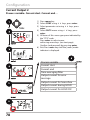
Temperature Compensation
TC process medium: Linear, ultrapure water, table
1) Press menu key.
2) Select CONF using keys, press enter.
3) Select parameter set using keys, press
enter.
4) Select CORRECTION menu using keys,
press enter.
5) All items of this menu group are indicated by
the “COR:” code.
Press enter to select menu,
edit using arrow keys (see next page).
Confirm (and proceed) using enter.
6) Exit: Press meas key until the [meas] mode
indicator is displayed.
5
6
80
Temperature compensation for
process medium
Current input,
external temp measurement
Current range
Current start
Current end
Configuration
Menu item
Action
Choices
Temp compensation, For pH measurement
only: Select temperature
process medium
compensation of the
process medium.
Linear: LIN
Ultrapure water:
PUREWTR
Table: USERTAB
Select using key,
proceed using enter.
Temp compensation, Enter the linear temperature compensation of the
linear
process medium.
Enter value using
keys.
Press enter to confirm.
Temp compensation, When you have selected
temperature compensatable
Confirm safety
prompt,
then enter values
(5°C step size)
tion via table (USERTAB),
you can enter values for
a TC table from 0 to 95 °C
in 5-K steps.
The analyzer displays
temperature values in
5 °C steps. You must specify the percent deviation
of the measured value
from each of these temperature values.
Intermediate values are
linearly interpolated.
TC compensation can be
defined separately for
parameter sets A and B.
0 ... 95 °C
(5°C step size)
81
Configuration
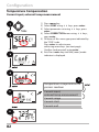
Temperature Compensation
Current input, external temp measurement
1) Press menu key.
2) Select CONF using keys, press enter.
3) Select parameter set using keys, press
enter.
4) Select CORRECTION menu using keys,
press enter.
5) All items of this menu group are indicated by
the “COR:” code.
Press enter to select menu,
edit using arrow keys (see next page).
Confirm (and proceed) using enter.
6) Exit: Press meas key until the [meas] mode
indicator is displayed.
5
6
82
Temperature compensation for
process medium
Current input,
external temp measurement
Current range
Current start
Current end
Configuration
5
Menu item
Action
Current input,
external temp
measurement
Only if enabled via TAN
and selected during configuration (SENSOR).
Select ON or OFF using
keys.
Choices
Press enter to confirm.
Current range
Select desired range
using keys.
Press enter to confirm.
Current start
Modify digit using
keys,
select next digit using
keys.
Input range:
Press enter to confirm.
Current end
Enter value using
keys.
Input range:
Press enter to confirm.
83
Configuration
CONTROL Input
Parameter set selection via external signal
1) Press menu key.
2) Select CONF using keys, press enter.
3) Select parameter set using , press enter.
4) Select CNTR_IN menu using keys, press
enter.
5) All items of this menu group are indicated by
the “IN:” code.
Press enter to select menu,
edit using arrow keys (see next page).
Confirm (and proceed) using enter.
6) Exit: Press meas key until the [meas] mode
indicator is displayed.
CONTROL input (function)
PARSET
FLOW
6
84
Configuration
5
Menu item
Action
Select function of
CONTROL input
Select using keys.
Press enter to confirm.
Choices
(selecting parameter
set A/B via signal at
CONTROL input)
External switchover of parameter sets
The parameter set A/B can be activated from outside by sending a
signal to the CONTROL input (e.g. from the process control system).
Power supply
12...24 V AC/DC
CONTROL
input
Process control system
Parameter set A
Parameter set B
0...2 V AC/DC
10...30 V AC/DC
85
Configuration
CONTROL Input
Flow measurement
1) Press menu key.
2) Select CONF using keys, press enter.
3) Select parameter set using , press enter.
4) Select CNTR_IN menu using keys, press
enter.
5) All items of this menu group are indicated by
the “IN:” code.
Press enter to select menu,
edit using arrow keys (see next page).
Confirm (and proceed) using enter.
6) Exit: Press meas key until the [meas] mode
indicator is displayed.
CONTROL input (function)
PARSET / FLOW
FLOW: ADJUST
86
Configuration
5
Menu item
Action
Choices
Select function of
CONTROL input
Select using keys.
Press enter to confirm.
PARSET
(selecting parameter
set A/B via signal at
CONTROL input)
Flow
(for connecting a pulseoutput flow meter)
Adjust to flow meter:
With “Flow” selected,
you must adjust the
device to the flow meter
used.
Enter value using arrow
keys. Press enter to
confirm.
12000 pulses/liter
In the alarm menu you can configure flow monitoring. When you have
set CONTROL to FLOW, you can specify 2 additional limit values for
maximum and minimum flow.
If the measured value lies outside this range, an alarm message and a
22-mA error signal (if configured) will be generated.
Display
Flow measurement in measuring mode
Display
Flow measurement (sensor monitor)
87
Configuration
Alarm Settings
Alarm delay. Sensocheck.
1) Press menu key.
2) Select CONF using keys, press enter.
3) Select parameter set using , press enter.
4) Select ALARM menu using keys, press
enter.
5) All items of this menu group are indicated by
the “ALA:” code.
Press enter to select menu,
edit using arrow keys (see next page).
Confirm (and proceed) using enter.
6) Exit: Press meas key until the [meas] mode
indicator is displayed.
5
6
88
Delay
Sensocheck
Alarm: CONTROL input
For flow monitoring:
Max. flow alarm
For flow monitoring:
Min. flow alarm
Configuration
5
Menu item
Action
Alarm delay
Enter value using
keys.
Press enter to confirm.
Sensocheck
Select Sensocheck
(continuous monitoring
of glass and reference
electrode)
Select ON or OFF using
keys.
Press enter to confirm.
(At the same time,
Sensoface is activated.
With OFF, Sensoface is
also switched off.)
Choices
Error messages can be signaled by a 22 mA output current (see Error Messages and
Configuration of Output 1/Output 2).
The alarm delay time delays the color change of the display backlighting to red
and the 22 mA signal (if configured).
89
Configuration
Alarm Settings
CONTROL input (FLOW MIN, FLOW MAX)
1) Press menu key.
2) Select CONF using keys, press enter.
3) Select parameter set using , press enter.
4) Select ALARM menu using keys, press
enter.
5) All items of this menu group are indicated by
the “ALA:” code.
Press enter to select menu,
edit using arrow keys (see next page).
Confirm (and proceed) using enter.
6) Exit: Press meas key until the [meas] mode
indicator is displayed.
5
6
90
ALARM: Delay
Alarm: Sensocheck
Alarm: CONTROL input
For flow monitoring:
Max. flow alarm
For flow monitoring:
Min. flow alarm
Configuration
5
Menu item
Action
Choices
CONTROL input
The CONTROL input can
generate an alarm when
assigned to FLOW (flow
monitoring) in the CONF
menu:
FLOW CNTR
Flow measurement:
allows monitoring the
minimum and maximum
flow (pulse counter)
Alarm
Minimum flow
Specify value
Default: 05.00 liters/h
Alarm
Maximum flow
Specify value
Default: 25.00 liters/h
FLOW MIN
FLOW MAX
91
Configuration
Time and Date
Tag Number
1
2
enter
3
1) Press menu key.
2) Select CONF using keys,
press enter.
3) Select parameter set A using keys,
press enter.
4) Select CLOCK or TAG using keys, press
enter.
5) All items of this menu group are indicated by
the “CLK:” or “TAG” code.
Press enter to select menu,
edit with arrow keys (see next page).
Confirm (and proceed) with enter.
6) Exit: Press meas key until the [meas] mode
indicator is displayed.
enter
4
5
enter
5
Time format
Time
Day and month
Year
Tag number
meas
6
92
enter
Configuration
Time and Date
Control of the calibration and cleaning cycles is based on the time and
date of the integrated real-time clock.
In measuring mode the time is shown in the lower display.
When using digital sensors, the calibration data is written in the s ensor
head.
In addition, the logbook entries (cf Diagnostics) are provided with a
time stamp.
Please note:
• After prolonged power outage (> 5 days) the time display is
replaced by dashes and cannot be used for processing.
Enter the correct time.
• There is no automatic switchover from winter to summer time!
Be sure to manually adjust the time!
Tag Number (“ TAG“)
You can enter a designation for the point of measurement (tag
number) in the lower display line. Up to 32 digits are possible.
Pressing meas (repeatedly) in the measuring mode indicates the tag
number.
Being part of the device configuration, the “TAG“ can be read out via
IrDA.
A standardized tag number helps, for example, to correctly re-install a
device after repair.
5
Menu item
Action
Choices
Tag number
Select character using
keys,
select next digit using
keys.
A...Z, 0...9, – + < > ? / @
Press enter to confirm.
The first 10 characters are
seen in the display without scrolling.
93
Digital Sensors
Stratos Pro can be operated with digital sensors. Due to the galvanic
isolation of Memosens sensors, earth or ground potentials have no
effect here. Therefore, a Solution Ground or measures for equipotential
bonding are not required.
Digital sensors can be calibrated and maintained in the lab.
This considerably simplifies on-site maintenance.
Memosens Sensors:
Calibration and Maintenance in the Lab
The “MemoSuite“ software allows calibrating Memosens sensors
under reproducible conditions at a PC in the lab. The sensor parameters are registered in a database. Documenting and archiving meet
the demands of FDA CFR 21 Part 11. Detailed reports can be output as
csv export for Excel.
Settings and
specifications
Currently connected sensor:
Sensor type, manufacturer,
order code and serial number
Function selection
(The selected function is
highlighted.)
Parameters of currently
connected sensor
Last calibration
(adjustment)
Display size of measured values:
When the cursor moves over a measured value, it
changes to a magnifying glass, allowing to magnify
the measured-value display at a mouse click.
94
Digital Sensors
The comprehensive display
options of the software
allow drawing conclusions
on the aging behavior of
the sensors at one glance
and making a reliable
forecast for predictive
maintenance.
Calibration history of several sensors
The software is available
as “Basic“ (calibration
function) or “Advanced“
(with sensor database)
version:
www.knick.de
History: Load diagrams of the sensors
Memosens Sensors: Configuring the Device
The sensor type is selected during Configuration.
The device only switches to measuring mode when the connected
sensor corresponds to the type configured (Sensoface is friendly):
MEMO
SENS
Otherwise, an error message is released.
The info icon is displayed. You can display
the error text in the bottom line using the
keys.
95
Digital Sensors
Connecting a Digital Sensor
Step
Action/Display
Remark
Connect sensor
Before a digital sensor
is connected, the error
message “No sensor“ is
displayed.
Wait until the
sensor data are
displayed.
Check sensor
data
Go to
measuring
mode
MEMO
SENS
MEMO
SENS
View sensor information
using keys,
press enter to confirm.
Press meas, info or enter
Replacing a Sensor
The hourglass in the
display blinks.
Display color changes to
green.
Sensoface is friendly
when the sensor data are
okay.
After 60 sec the device
automatically returns to
measuring mode (timeout).
A sensor should only be replaced during HOLD mode to prevent unintended reactions of the outputs or contacts. When you first want to
calibrate the new sensor, it can also be replaced in calibration mode.
96
Digital Sensors
Step
Action/Display
Remark
Select HOLD
mode
Press menu key to call
the selection menu,
select HOLD using the
keys, press enter
to confirm.
Now the device is in HOLD
mode. The HOLD mode can also
be activated externally via the
HOLD input. During HOLD the
output current is frozen at its last
value or set to a fixed value.
Disconnect old
sensor,
connect new
sensor.
Wait until the
sensor data are
displayed.
Check sensor
data
Check
measured
values,
then
exit HOLD.
Temporary messages are displayed during the replacement
but neither output to the alarm
contact nor entered in the logbook.
MEMO
SENS
MEMO
SENS
You can view the sensor manufacturer and type, serial number,
and last calibration date.
View sensor information using keys,
press enter to confirm.
The sensor replacement is
Hit meas key:
entered in the extended
Return to the selection menu. Hold meas logbook.
key depressed: Device
switches to measuring
mode.
97
Calibration
Please note:
• All calibration procedures must be performed by trained personnel. Incorrectly set parameters may go unnoticed, but change the
measuring properties.
• The response time of the sensor and temperature probe is
considerably reduced when the sensor is first moved about
in the buffer solution and then held still.
• The device can only operate properly when the buffer solutions
used correspond to the configured set. Other buffer solutions, even
those with the same nominal values, may demonstrate a different
temperature response. This leads to measurement errors.
When using ISFET sensors or sensors with a zero point other
than pH 7, the nominal zero point must be adjusted each time a new
sensor is connected. This is important if you want to obtain reliable
Sensoface messages. The Sensoface messages issued during all further
calibrations are based on this basic calibration.
98
Selecting a Calibration Mode
Calibration is used to adapt the device to the individual sensor
characteristics, namely asymmetry potential and slope.
Access to calibration can be protected with a passcode
(SERVICE menu).
First, you open the calibration menu and select the calibration mode:
CAL_PH
Depending on configuation setting:
AUTO Automatic buffer recognition (Calimatic)
MAN Manual buffer input
DAT
Input of premeasured electrode data
CAL_ORP
ORP calibration
P_CAL
Product calibration (calibration with sampling)
ISFET-ZERO Zero adjustment. Required for ISFET sensors,
subsequently you can conduct either a
one or a two-point calibration.
CAL_RTD
Temperature probe adjustment
To preset CAL_PH (CONF menu / configuration):
1)Hold meas key depressed (> 2 s) (measuring mode)
2)Press menu key: the selection menu appears
3)Select CONF mode using left / right arrow key
4)Select “SENSOR“ – “CALMODE“: AUTO, MAN, or DAT.
Press enter to confirm
Selection menu
Selected mode
(blinks)
1
4
3
2
99
Zero adjustment
Zero Adjustment (ISFET)
This adjustment allows the use of ISFET sensors with differing nominal
zero (pH only). The function is available when Sensor selection = ISFET
has been set during configuration. Zero adjustment is disabled for any
other sensors.
The adjustment is made using a zero buffer (pH 7.00).
Permitted range for buffer value: pH 6.5 ... 7.5.
Temperature-corrected input. Maximum zero offset: ± 200 mV.
Display
Action
Remark
Select Calibration.
Press enter to proceed.
100
Ready for calibration.
Hourglass blinks.
Display (3 sec)
Now the device is in
HOLD mode.
Immerse sensor in a pH
7.00 buffer. Enter the
temperature-corrected
pH value in the range
6.50 to 7.50 using the
arrow keys (see buffer
table).
Confirm with enter.
Stability check.
The measured value
[mV] is displayed.
The “hourglass” icon is
blinking.
If the zero offset of
the sensor is too
large (> ± 200 mV),
a CAL ERR error
message is generated. In that case the
electrode cannot be
calibrated.
Please note:
Stability check can
be stopped (by
pressing enter).
However, this reduces calibration
accuracy.
Zero Adjustment (ISFET)
Display
Action
Remark
At the end of the adjustment procedure
the zero offset [mV] of
the sensor is displayed
(based on 25 °C).
Sensoface is active.
Press enter to proceed.
This is not the final
calibration value of
the sensor! Asymmetry potential
and slope must be
determined with a
complete 2-point
calibration.
Use the arrow keys to
select:
• Repeat
(repeat calibration) or
• Measuring.
Confirm by pressing
enter.
Place sensor in process. After end of calibraPress enter to end zero tion, the outputs recalibration.
main in HOLD mode
for a short time.
Note for zero adjustment
After having adjusted the zero offset, be sure to calibrate the sensor
following one of the procedures as described on the next pages.
101
Adjustment (Calimatic)
Automatic Calibration (Calimatic)
The AUTO calibration mode and the type of temperature detection
are selected during configuration. Make sure that the buffer solutions
used correspond to the configured buffer set. Other buffer solutions,
even those with the same nominal values, may demonstrate a different temperature response. This leads to measurement errors.
Display
Action
Remark
Select Calibration.
Press enter to proceed.
Ready for calibration.
Hourglass blinks.
Select calibration
method: CAL_PH
Press enter to proceed.
Remove the sensor and
temperature probe,
clean them, and immerse them in the first
buffer solution (in any
order). Start by pressing
enter
Buffer recognition.
While the “hourglass”
icon is blinking, the
sensor and temperature
probe remain in the first
buffer solution.
Buffer recognition
terminated, the nominal buffer value is
displayed.
102
Display (3 sec)
Now the device is in
HOLD mode.
When manual input
of temperature has
been configured, the
temp value in the
display blinks and
can be edited using
the arrow keys.
The response time
of the sensor and
temperature probe
is considerably
reduced when the
sensor is first moved
about in the buffer
solution and then
held still.
Automatic Calibration (Calimatic)
Display
Action
Remark
At the end of the stability check, the value will
be saved and the asymmetry potential will be
displayed.
Calibration with the first
buffer is terminated.
Remove the sensor and
temp probe from the
first buffer solution and
rinse them thoroughly.
Use the arrow keys to
select:
• END (1-point cal)
• CAL2 (2-point cal)
• REPEAT
Press enter to proceed.
Please note:
Stability check can
be stopped after
10 sec (by pressing
enter). However, this
reduces calibration
accuracy. Display for
1-point cal:
2-point calibration:
Immerse sensor and
temperature probe
in the second buffer
solution.
Press enter to start.
Retract sensor and
temp probe out of
second buffer, rinse off,
re-install.
Press enter to proceed.
The calibration
process runs as for
the first buffer.
Use the arrow keys to
select:
• MEAS (exit)
• REPEAT
Press enter to proceed.
Exit: HOLD is deactivated with delay.
When 2-point cal is
ended:
Sensoface is active.
End by pressing
enter
The slope and asymmetry potential of
the sensor (based on
25 °C) are displayed.
103
Manual Calibration with Buffer Entry
The MAN calibration mode and the type of temperature detection
are selected during configuration. For calibration with manual buffer
specification, you must enter the pH value of the buffer solution used
in the device for the proper temperature. Any desired buffer solution
can be used for calibration.
Display
Action
Remark
Select Calibration.
Press enter to proceed.
Ready for calibration.
Hourglass blinks.
Remove the sensor and
temperature probe,
clean them, and immerse them in the first
buffer solution.
Press enter to start.
Display (3 sec)
Now the device is in
HOLD mode.
When manual input
of temperature has
been configured, the
temp value in the
display blinks and
can be edited using
the arrow keys.
Enter the pH value of
The response time
your buffer solution for of the sensor and
the proper temperature. temperature probe
While the “hourglass”
is considerably
icon is blinking, the
reduced when the
sensor and temperature sensor is first moved
probe remain in the
about in the buffer
buffer solution.
solution and then
held still.
104
Manual Calibration with Buffer Entry
Display
Action
Remark
At the end of the stability check, the value will
be saved and the asymmetry potential will be
displayed.
Calibration with the first
buffer is terminated.
Remove the sensor and
temp probe from the
first buffer solution and
rinse them thoroughly.
Use the arrow keys to
select:
• END (1-point cal)
• CAL2 (2-point cal)
• REPEAT
Press enter to proceed.
Please note:
Stability check can
be stopped after
10 sec (by pressing
enter). However, this
reduces calibration
accuracy. Display for
1-point cal:
2-point calibration:
Immerse sensor and
temperature probe
in the second buffer
solution.
Enter pH value.
Press enter to start.
Rinse sensor and temperature probe and
reinstall them.
Press enter to proceed.
Use the arrow keys to
select:
• MEAS (exit)
• REPEAT
Press enter to proceed.
Exit: HOLD is deactivated with delay.
Sensoface is active.
End by pressing
enter
The calibration
process runs as for
the first buffer.
Display of slope and
new asymmetry
potential (based on
25 °C).
When 2-point cal is
ended:
105
Data Entry of Premeasured Sensors
The DAT calibration mode must have been preset during
configuration.
You can directly enter the values for slope and asymmetry potential
of a sensor. The values must be known, e.g. determined beforehand in
the laboratory.
Display
Action
Remark
Select Calibration.
Press enter to proceed.
“Data Input“
Ready for calibration.
Hourglass blinks.
Display (3 sec)
Now the device is in
HOLD mode.
Enter asymmetry
potential [mV].
Press enter to proceed.
Enter slope [%].
The device displays
the new slope and
asymmetry potential
(at 25 °C).
Sensoface is active.
Use the arrow keys to
select:
• MEAS (exit)
• REPEAT
Press enter to proceed.
106
Exit:
HOLD is deactivated
with delay.
Converting Slope to mV
Converting slope [%] to slope [mV/pH] at 25 °C
%
78
80
82
84
86
88
90
92
94
96
98
100
102
mV/pH
46.2
47.4
48.5
49.7
50.9
52.1
53.3
54.5
55.6
56.8
58.0
59.2
60.4
Converting asymmetry potential to sensor zero point
ZERO = 7 -
VAS[mV]
S [mV / pH]
ZERO
=Sensor zero
VAS
=Asymmetry potential
S
=Slope
107
Product calibration
Product Calibration (pH)
Calibration by sampling (one-point calibration).
During product calibration the sensor remains in the process.
The measurement process is only interrupted briefly.
Procedure:
1)The sample is measured in the lab or directly on the site using a portable meter. To ensure an exact calibration, the sample temperature
should correspond to the measured process temperature.
During sampling the device saves the currently measured value and
then returns to measuring mode. The “calibration“ mode indicator
blinks.
2)In the second step you enter the measured sample value in the
device. From the difference between the stored measured value and
entered sample value, the device calculates the new asymmetry
potential.
If the sample is invalid, you can take over the value stored during
sampling. In that case the old calibration values are stored.
Afterwards, you can start a new product calibration.
Display
Action
Remark
Select product
calibration: P_CAL.
Press enter to proceed.
108
Ready for calibration.
Hourglass blinks.
Display (3 sec)
Now the device is in
HOLD mode.
Take sample and save
value.
Press enter to proceed.
Now the sample can
be measured.
Product Calibration (pH)
Display
Action
Remark
The device returns to
measuring mode.
From the blinking
CAL mode indicator
you see that product
calibration has not
been terminated.
Display (3 sec)
Now the device is in
HOLD mode.
Product calibration
step 2
End of calibration
The stored value is
displayed (blinking) and
can be overwritten with
the measured sample
value.
Press enter to proceed.
Display of new asymTo repeat calibrametry potential (based tion: Select REPEAT,
on 25°C).
then press enter
Sensoface is active.
To exit calibration:
Select MEAS, then press
enter
After end of calibration, the outputs remain in
HOLD mode for a short time.
109
ORP (Redox) Calibration
The potential of a redox sensor is calibrated using a redox (ORP) buffer
solution. In the course of that, the difference between the measured
potential and the potential of the calibration solution is determined
according to the following equation. During measurement this difference is added to the measured potential.
mVORP = mVmeas – ΔmV
mVORP
= displayed ORP
mVmeas
= direct sensor potential
ΔmV
=delta value, determined during
calibration
The sensor potential can also be related to another reference system
– e.g. the standard hydrogen electrode. In that case the temperaturecorrected potential (see table) of the reference electrode used must
be entered during calibration. During measurement, this value is then
added to the ORP measured.
Please make sure that measurement and calibration temperature are
the same since the temperature behavior of the reference electrode is
not automatically taken into account.
Temperature dependence of commonly used reference systems
measured against SHE
Temperature
[°C]
Ag/AgCl/KCl
1 mol/l
[∆mV]
Ag/AgCl/KCl
3 mol/l
[∆mV]
Thalamid
[∆mV]
Mercury
sulfate
[∆mV]
0
10
20
25
30
40
50
60
70
80
249
244
240
236
233
227
221
214
207
200
224
217
211
207
203
196
188
180
172
163
-559
-564
-569
-571
-574
-580
-585
-592
-598
-605
672
664
655
651
647
639
631
623
613
603
110
ORP Calibration
Display
Action
Remark
Select ORP calibration,
proceed with enter
Remove the sensor and temperature
probe, clean them, and
immerse them in the
redox buffer.
Enter setpoint value for
redox buffer.
Press enter to proceed.
Display (3 sec)
Now the device is in
HOLD mode.
The ORP delta value is
displayed (based on
25°C).
Sensoface is active.
Press enter to proceed.
To repeat calibration:
Select REPEAT.
To exit calibration:
Select MEAS, then press
enter
After end of calibration, the outputs remain in HOLD mode
for a short time.
111
Temp probe adjustment
Temp Probe Adjustment
Display
Action
Remark
Select temp adjustment. Press enter to
proceed.
Wrong settings
change the
measurement
properties!
Measure the temperature of the process medium using an external
thermometer.
Display (3 sec)
Now the device is in
HOLD mode.
Enter the measured
temperature value.
Maximum difference:
10 K.
Press enter to proceed.
Display of actual
temperature (uncompensated) in the
lower display.
The corrected temperature value is displayed.
Sensoface is active.
To exit calibration:
Select MEAS, then press
enter
To repeat calibration:
Select REPEAT, then
press enter
After calibration is
ended, the device will
switch to measuring
mode.
112
After end of calibration, the outputs remain in HOLD mode
for a short time.
Measurement
Display
Remark
From the configuration or calibration menus,
you can switch the device to measuring
mode by pressing the meas key.
In the measuring mode the main display
shows the configured process variable (pH,
or AM/PM and °F:
ORP [mV], or temperature), the secondary display shows the time and the second
configured process variable (pH, ORP [mV],
or temperature). The [meas] mode indicator
lights and the active parameter set (A/B) is
indicated.
By pressing the meas key you can step through the following
displays. When no key has been pressed for 60 sec, the device
returns to the standard display.
1)Selecting the parameter set
(if set to “manual“ in the configuration).
Select the desired parameter set using
thearrow keys (PARSET A or PARSET B
blinks in the lower display line).
Confirm by pressing enter.
Further displays
(each with meas).
2)Display of tag number (“TAG“)
3)Display of time and date
113
Diagnostics (DIAG)
Diagnostics
In the Diagnostics mode you can access the following menus without
interrupting the measurement:
CALDATA
Viewing the calibration data
SENSOR
Viewing the sensor data
SELFTEST
Starting a device self-test
LOGBOOK
Viewing the logbook entries
MONITOR
Displaying currently measured values
VERSION
Displaying device type, software version, serial number
Access to diagnostics can be protected with a passcode
(SERVICE menu).
Please note:
HOLD is not active during Diagnostics mode!
Action
Key
Remark
Activate
Diagnostics
Press menu key to call the selection
menu.
(Display color changes to turquoise.)
Select DIAG using keys,
confirm by pressing enter.
Select
diagnostics
option
Use keys to select from:
Caldata Sensor Selftest
Logbook Monitor VERSION
See next pages for further
proceeding.
Exit
114
meas
Exit by pressing meas.
Diagnostics
Display
Menu item
Display of calibration data
Select CALDATA using, confirm with enter.
Use thekeys to select the desired parameter from
the bottom line of the display (LAST_CAL ISFET-ZERO
ZERO SLOPE NEXT_CAL).
The selected parameter is shown in the main display.
Press meas to return to measurement.
Display of sensor data
For analog sensors, the type is displayed
(STANDARD / ISFET). Not applicable for digital
transmitters (-MSPH).
For digital sensors, the manufacturer, type,
serial number, and last calibration date is displayed.
In each case Sensoface is active.
Display data using keys,
return by pressing enter or meas.
115
Diagnostics
Display
Menu item
Device self-test
(To abort, you can press meas.)
1) Display test: Display of all segments with
changing background colors (white/green/red).
Press enter to proceed.
2) RAM test: Hourglass blinks, then display of
--PASS-- or --FAIL-Press enter to proceed.
3) EEPROM test: Hourglass blinks, then display of
--PASS-- or --FAIL-Press enter to proceed.
4) FLASH test: Hourglass blinks, then display of
--PASS-- or --FAIL-Press enter to proceed.
5) Module test: Hourglass blinks, then display of
--PASS-- or --FAIL-Press enter or meas
to return to measuring mode.
116
Diagnostics
Display
Menu item
Displaying the logbook entries
Select LOGBOOK using, press enter to confirm.
Using the keys, you can scroll backwards and
forwards through the logbook (entries -00-...-99-),
-00- being the last entry.
If the display is set to date/time, you can search for a
particular date using the keys.
Pressto view the corresponding message text.
If the display is set to the message text, you can
search for a particular message using the keys.
Pressto display the date and time.
Press meas to return to measurement.
Extended logbook / Audit Trail (via TAN)
Using the keys, you can scroll backwards and
forwards through the extended logbook (entries
-000-...-199-), -000- being the last entry.
Display: CFR
Audit Trail also records function activations
(CAL CONFIG SERVICE), some Sensoface messages
(cal timer, wear) and opening of the enclosure.
117
Diagnostics
Display
Menu item
Display of currently measured values
(sensor monitor)
Display examples:
Select MONITOR using, press enter to confirm.
Use the keys to select the desired parameter
from the bottom line of the display: mV_PH mV_ORP
RTD R_GLASS R_REF I-INPUT (for digital sensors also:
OPERATION TIME SENSOR WEAR LIFETIME CIP SIP
AUTOCLAVE, for ISM sensors in addition:
ACT (adaptive calibration timer)
TTM (adaptive maintenance timer)
DLI (Dynamic Life Time Indicator). The selected
parameter is shown in the main display.
Press meas to return to measurement.
Display mV_pH
(for validation, sensor can be immersed in a calibration solution, for example, or the device is checked by
using a simulator)
Display of remaining dynamic lifetime
(only for digital sensors, however not for MEMOSENS)
Display of sensor operating time
(for digital sensors only)
Version
Display of device type, software/hardware version,
and serial number for all device components.
Use the keys to switch between software and
hardware version. Press enter to proceed to next
device component.
118
Service (SERVICE) A
Service
In the Service mode you can access the following menus:
MONITOR
Displaying currently measured values
SENSOR
ISM only:
Resetting TTM
Incrementing autoclaving counter
OUT1
Testing current output 1
OUT2
Testing current output 2
IRDA
Activating and communicating via the IrDA interface
CODES
Assigning and editing passcodes
DEFAULT
Resetting the device to factory settings
OPTION
Enabling options via TAN.
Please note:
HOLD is active during Service mode!
Action
Key/Display
Remark
Activate
Service
Press menu key to call the selection
menu.
Select SERVICE using keys,
press enter to confirm.
Passcode
Enter passcode “5555“ for service
mode using the keys.
Press enter to confirm.
Display
Exit
In service mode the following icons
are displayed:
• [diag] mode indicator
• HOLD triangle
• Service (wrench)
meas
Exit by pressing meas.
119
Service
Menu item
Remark
Displaying currently measured values
(sensor monitor) with HOLD mode activated:
Select MONITOR using, press enter to confirm.
Select variable in the bottom text line using.
Display example:
The selected parameter is shown in the main display.
As the device is in HOLD mode, you can perform
validations using simulators without influencing the
signal outputs.
Press meas to return to the service menu.
Return to measurement: Press meas once more.
Resetting the adaptive maintenance timer
Here, the interval is reset to its initial value. To do so,
select “TTM RESET = YES“ and confirm by pressing
enter.
Incrementing the autoclaving counter
After having completed an autoclaving process,
you must increment the autoclaving count.
To do so, select “YES” and confirm by pressing enter.
The device confirms with
“INCREMENT AUTOCLAVE CYCLE“.
Specifying current at outputs 1 and 2:
Select OUT1 or OUT2 using thekeys,
press enter to confirm.
Enter a valid current value for the respective output
using keys.
Press enter to confirm.
For checking purposes, the actual output current is
shown in the bottom right corner of the display.
End by pressing enter or meas.
120
Service
Menu item
Remark
IrDA communication:
Select IRDA using,
press enter to confirm.
When IrDA communication is active, the device
remains in the HOLD mode for reasons of safety.
Further operation is performed via IrDA.
End communication by pressing meas.
Exception: Firmware update
(must not be interrupted!)
Assigning passcodes:
In the “SERVICE - CODES“ menu you can assign passcodes to DIAG, HOLD, CAL, CONF and SERVICE modes
(Service preset to 5555).
When you have lost the Service passcode, you have
to request an “Ambulance TAN“ from the manufacturer specifying the serial number of your device.
To enter the “Ambulance TAN“, call the Service function and enter passcode 7321. After correct input of
the ambulance TAN the device signals “PASS“ for 4 sec
and resets the Service passcode to 5555.
Reset to factory settings:
In the “SERVICE - DEFAULT“ menu you can reset the
device to factory settings.
Caution!
After a reset to factory setting the device must
be reconfigured completely, including the sensor
parameters!
Releasing an option:
Options come with a “transaction number“ (TAN).
To release the option, enter this TAN and confirm by
pressing enter.
121
Measuring
Time
out
OUT 2
Operating status
OUT 1
Operating States
-
DIAG
60 s
CAL
No
CONF
20
min
20
min
20
min
20
min
No
SERVICE
SERVICE OUT 1
SERVICE OUT 2
HOLD
Explanation: as configured (Last/Fix or Last/Off )
active
manual
122
A2...X: Supply Units and Connection
Recommended Power Supply Units:
Order No.:
Repeater power supply, Ex, 24 V AC/DC,
output 0/4...20 mA
Repeater power supply, Ex, 90...253 V AC,
output 4...20 mA
Repeater power supply, Ex, 90...253 V AC,
HART, output 4...20 mA
Repeater power supply, Ex, 24 V AC/DC,
output 4...20 mA
Repeater power supply, Ex, 24 V AC/DC,
HART, output 4...20 mA
Repeater power supply, non-Ex, 24 V DC,
output 4...20 mA
Repeater power supply, non-Ex, 24 V DC,
HART, output 0/4...20 mA / 0...10 V
Connection to Supply Units
+
Supply unit 1
-
+
Hazardous-area
requirements for cable:
Between the wires:
Solid insulation ≥ 0.5 mm
Test voltage ≥ 500 V
Supply unit 2
-
123
Product Line and Accessories
Order Code Stratos Pro A 2...
Example
2-wire / 4-20 mA
A
2
Communication
Without (HART retrofittable via TAN) 0
Version number
Version
Approvals
General Safety
ATEX / IECEx Zone 2
ATEX / IECEx / FM / CSA Zone 1 / Cl 1 Div 1
Other approvals
1
N
B
X
Z
Measuring channel
Memosens pH / Redox
digital
Memosens Cond
digital
Memosens Oxy
digital
Dual COND (2x2-electrode sensors, analog)
N
pH / ORP value
Measuring module
(ISM digital per TAN)
Cond, 2-/4-electrode
Measuring module
Conductivity, electrodeless Measuring module
Oxygen (ISM digital and
Measuring module
traces per TAN)
Options
Without 2nd current output
With 2nd current output
TAN options
HART
Logbook
Extended logbook (Audit Trail)
Trace oxygen measurement
Current input + 2 digital inputs
ISM digital
Mounting accessories
Pipe-mount kit
Protective hood
Panel-mount kit
124
0
1
Specifications
pH/mV input
Input for pH or ORP sensors or ISFET
Input
Glass electrode or ISFET
Input
Reference electrode
Input
ORP electrode (e.g. platinum) or auxiliary
electrode for impedance measurement
Measuring range
–1500 ... +1500 mV
Display range
pH value
–2.00 ... 16.00
ORP
–1999 ... +1999 mV
Input resistance
> 1 x 10¹² Ω
Input current
< 1 x 10-12 A
Impedance range
0.5 ... 1000 MΩ (± 20%)
Input resistance
> 1 x 10¹⁰ Ω
Glass electrode input5)
Reference electrode input5)
< 1 x 10⁻¹⁰ A
Input current
Impedance range
Measurement error 1,2,3)
2)
0.5 ... 200 kΩ (± 20%)
pH value
< 0.02
TC: 0.002 pH/K
mV value
< 1 mV
TC: 0.1 mV/K
pH sensor standardization *
pH calibration
Operating modes
BUF
Calibration with Calimatic
automatic buffer recognition
MAN
Manual calibration with
entry of individual buffer values
DAT
Data entry of pre-measured electrodes
Product calibration
Calimatic buffer sets *
-01- Mettler-Toledo
2.00/4.01/7.00/9.21
-02- Knick CaliMat
2.00/4.00/7.00/9.00/12.00
-03- Ciba (94)
2.06/4.00/7.00/10.00
-04- NIST technical
1.68/4.00/7.00/10.01/12.46
-05- NIST standard
1.679/4.006/6.865/9.180
-06- HACH
4.01/7.00/10.01
-07- WTW techn. buffers 2.00/4.01/7.00/10.00
-08- Hamilton
4.01/7.00/10.01/12.00
-09- Reagecon
2.00/4.00/7.00/9.00/12.00
-10- DIN 19267
1.09/4.65/6.79/9.23/12.75
-U1-
Specifiable buffer set with 2 buffer solutions
125
Specifications
Zero adjustment
± 200 mV (for ISFET)
Max. calibration range
Asymmetry potential
±60 mV
Slope
80 ... 103 % (47.5 ... 61 mV/pH)
(possibly restricting notes from Sensoface)
ORP sensor standardization* ORP calibration (zero adjustment)
Max. calibration range
–700 ... +700 ΔmV
Adaptive cal timer *
(Pat. DE 101 41 408)
Interval 0000 ... 9999 h
Sensocheck
Automatic monitoring of glass and reference electrode (can be disabled)
Delay
Approx. 30 s
Sensoface
Provides information on the sensor condition,
evaluation of zero/slope, response time, calibration interval,
wear, Sensocheck, can be switched off
Temperature input
Pt100 / Pt1000 / NTC 30 kΩ *
2-wire connection, adjustable
Measuring range
Pt 100/Pt 1000
-20.0 ... +200.0 °C / –4 ... +392 °F
NTC 30 kΩ
-20.0 ... +150.0 °C / –4 ... +302 °F
NTC 8.55 kΩ (Mitsubishi) –10.0 ... +130.0 °C / +14 ... +266 °F
Balco 3 kΩ
–20.0 ... +130.0 °C / –4 ... +266 °F
Adjustment range
10 K
Resolution
0.1 °C / 0.1 °F
Measurement error 1,2,3)
< 0.5 K (< 1K for Pt100; < 1K for NTC >100°C)
Temperature compensation
of process medium
Linear -19.99 ... +19.99 %/K (reference temp 25 °C)
ultrapure water, user-defined table
ISM input
“One wire“ interface for operation with ISM (digital sensors)
(6 V / Ri= approx. 1.2 kΩ)
Power output
for operating an ISFET adapter
+3 V / 0.5 mA
–3 V / 0.5 mA
126
Specifications
I input (TAN)
Current input 0/4 ... 20 mA / 50 Ω for external temperature signal
Start/end of scale
Configurable –20 ... 200 °C (-4 ... +392 °F)
Characteristic
Linear
Measurement error 1.3)
< 1% current value + 0.1 mA
HOLD input
Galvanically separated (OPTO coupler)
Function
Switches device to HOLD mode
Switching voltage
0 ... 2 V (AC/DC)
HOLD inactive
10 ... 30 V (AC/DC)
HOLD active
CONTROL input
Galvanically separated (OPTO coupler)
Function
Selecting parameter set A/B or flow measurement
Parameter set A/B
Control input
FLOW
Pulse input for flow measurement 0 ... 100 pulses/s
Pulse amplitude 10 ... 30 V DC
Message
via 22 mA
Display
00.0 … 99.9 l/h
Output 1
Current loop, 4 ... 20 mA, floating, protected against inverse polarity
HART communication (see further below for specifications)
Supply voltage
14 ... 30 V
Process variable *
pH, ORP or temperature
Characteristic
Linear
Overrange *
22 mA in the case of error messages
Output filter *
PT1 filter, time constant 0 ... 120 s
Measurement error 1)
< 0.25 % current value + 0.025 mA
Start/end of scale *
Configurable within selected range
Minimum span
pH 2.00 / 200 mV / 20 K / 36 °F
0 ... 2 V (AC/DC)
10 ... 30 V (AC/DC)
Parameter set A
Parameter set B
127
Specifications
Output 2
Current loop, 4 ... 20 mA, floating, protected against inverse polarity
Supply voltage
14 ... 30 V
Process variable *
pH, ORP or temperature
Overrange *
22 mA in the case of error messages
Output filter *
PT1 filter, time constant 0 ... 120 s
Measurement error 1)
Start/end of scale
*
< 0.25 % of current value + 0.05 mA
Configurable within selected range
Minimum span
pH 2.00 / 200 mV / 20 K / 36 °F
Real-time clock
Different time and date formats selectable
Power reserve
> 5 days
Display
LC display, 7-segment with icons
Main display
Character height approx. 22 mm, unit symbols approx. 14 mm
Secondary display
Character height approx. 10 mm
Text line
14 characters, 14 segments
Sensoface
3 status indicators (friendly, neutral, sad face)
Mode Indicators
meas, cal, conf, diag
Further icons for configuration and messages
Alarm indication
Display blinks, red backlighting
Keypad
Keys: meas, menu, info, 4 cursor keys, enter
HART communication
HART version 6
Digital communication by FSK modulation of output current 1
Device identification, measured values, status and messages,
parameter setting, calibration, records
IrDA interface
Infrared interface for firmware update
FDA 21 CFR Part 11
Access control by editable passcodes
Logbook entry and flag via HART
Message and logbook entry when enclosure is opened
128
Specifications
Diagnostics functions
Calibration data
Calibration date, zero, slope, response time
Device self-test
Display test, automatic memory test (RAM, FLASH, EEPROM),
module test
Logbook
100 events with date and time
Extended logbook (TAN)
Audit Trail: 200 events with date and time
Service functions
Sensor monitor
Display of direct sensor signals
Current source
Current specifiable for output 1 and 2 (04.00 ... 22.00 mA)
IrDA
Activating the IrDA function
Passcodes
Assigning passcodes for menu access
Factory setting
Resetting all parameters to factory setting
TAN
Enabling optionally available additional functions
Data retention
Parameters, calibration data, logbook > 10 years (EEPROM)
EMC
EN 61326-1 (General Requirements)
Emitted interference
Class B (residential area)
Immunity to interference
Industry EN 61326-2-3
Nominal operating conditions
Ambient temperature
–20 ... +65 °C
Transport/Storage temperature
–30 ... +70 °C
Relative humidity
10 ... 95% not condensing
Supply voltage
14 ... 30 V
129
Specifications
Explosion protection
Explosion protection
Memosens Ex wiring
130
Uo
(V)
Io
(mA)
Po
(mW)
Ci
(μH)
Li
(μH)
5
124
155
10.6
0
Specifications
Enclosure
Molded enclosure made of glass-reinforced PBT, PC
Mounting
Wall, pipe/post or panel mounting
Color
Gray, RAL 7001
Ingress protection
IP 67, NEMA 4X
Flammability
UL 94 V-0
Dimensions
148 mm x 148 mm
Control panel cutout
138 mm x 138 mm to DIN 43 700
Weight
Approx. 1200 g
Cable glands
3 knockouts for M20 x 1.5 cable glands
2 knockouts for NPT ½” or rigid metallic conduit
Connections
Terminals, conductor cross-section max. 2.5 mm2
*) User-defined
1) Acc. to EN 60746, at nominal operating conditions
2) ± 1 count
3) Plus sensor error
5) At room temperature
131
Specifications
132
Buffer Tables
-01- Mettler-Toledo
(corresponds to former “Knick technical buffers”)
°C
0
5
10
15
20
25
30
35
40
45
50
55
60
65
70
75
80
85
90
95
pH
2.03
2.02
2.01
2.00
2.00
2.00
1.99
1.99
1.98
1.98
1.98
1.98
1.98
1.99
1.99
2.00
2.00
2.00
2.00
2.00
4.01
4.01
4.00
4.00
4.00
4.01
4.01
4.02
4.03
4.04
4.06
4.08
4.10
4.13
4.16
4.19
4.22
4.26
4.30
4.35
7.12
7.09
7.06
7.04
7.02
7.00
6.99
6.98
6.97
6.97
6.97
6.98
6.98
6.99
7.00
7.02
7.04
7.06
7.09
7.12
9.52
9.45
9.38
9.32
9.26
9.21
9.16
9.11
9.06
9.03
8.99
8.96
8.93
8.90
8.88
8.85
8.83
8.81
8.79
8.77
133
Buffer Tables
-02-
°C
Knick CaliMat
(Merck Titrisols, Riedel-de-Haen Fixanals)
pH
Order No. CS-P0200A/...
CS-P0400A/...
CS-P0700A/...
CS-P0900A/...
CS-P1200A/...
0
5
10
15
20
25
30
35
40
50
60
70
80
90
4.05
4.04
4.02
4.01
4.00
4.01
4.01
4.01
4.01
4.01
4.00
4.00
4.00
4.00
7.09
7.07
7.04
7.02
7.00
6.99
6.98
6.96
6.96
6.96
6.96
6.96
6.98
7.00
9.24
9.16
9.11
9.05
9.00
8.95
8.91
8.88
8.85
8.79
8,73
8,70
8,66
8,64
12.58
12.39
12.26
12.13
12.00
11.87
11.75
11.64
11.53
11.31
11.09
10.88
10.68
10.48
134
2.01
2.01
2.01
2.00
2.00
2.00
2.00
2.00
2.00
2.00
2.00
2.00
2.00
2.00
Buffer Tables
-03-
Ciba (94) buffers
Nominal values: 2.06 4.00 7.00 10.00
°C
0
5
10
15
20
25
30
35
40
45
50
55
60
65
70
75
80
85
90
95
pH
2.04
2.09
2.07
2.08
2.09
2.08
2.06
2.06
2.07
2.06
2.06
2.05
2.08
2.07*
2.07
2.04*
2.02
2.03*
2.04
2.05*
4.00
4.02
4.00
4.00
4.01
4.02
4.00
4.01
4.02
4.03
4.04
4.05
4.10
4.10*
4.11
4.13*
4.15
4.17*
4.20
4.22*
7.10
7.08
7.05
7.02
6.98
6.98
6.96
6.95
6.94
6.93
6.93
6.91
6.93
6.92*
6.92
6.92*
6.93
6.95*
6.97
6.99*
10.30
10.21
10.14
10.06
9.99
9.95
9.89
9.85
9.81
9.77
9.73
9.68
9.66
9.61*
9.57
9.54*
9.52
9.47*
9.43
9.38*
* extrapolated
135
Buffer Tables
-04-
°C
0
5
10
15
20
25
30
35
40
45
50
55
60
65
70
75
80
85
90
95
NIST technical buffers
pH
1.67
1.67
1.67
1.67
1.675
1.68
1.68
1.69
1.69
1.70
1.705
1.715
1.72
1.73
1.74
1.75
1.765
1.78
1.79
1.805
* Values complemented
136
4.00
4.00
4.00
4.00
4.00
4.005
4.015
4.025
4.03
4.045
4.06
4.075
4.085
4.10
4.13
4.14
4.16
4.18
4.21
4.23
7.115
7.085
7.06
7.04
7.015
7.00
6.985
6.98
6.975
6.975
6.97
6.97
6.97
6.98
6.99
7.01
7.03
7.05
7.08
7.11
10.32
10.25
10.18
10.12
10.06
10.01
9.97
9.93
9.89
9.86
9.83
9.83*
9.83*
9.83*
9.83*
9.83*
9.83*
9.83*
9.83*
9.83*
13.42
13.21
13.01
12.80
12.64
12.46
12.30
12.13
11.99
11.84
11.71
11.57
11.45
11.45*
11.45*
11.45*
11.45*
11.45*
11.45*
11.45*
Buffer Tables
-05-
°C
0
5
10
15
20
25
30
37
40
45
50
55
60
65
70
75
80
85
90
95
NIST standard buffers
NIST Standard (DIN 19266 : 2000-01)
pH
1.668
1.670
1.672
1.676
1.680
1.685
1.694
1.697
1.704
1.712
1.715
1.723
4.004
4.001
4.001
4.003
4.008
4.015
4.028
4.036
4.049
4.064
4.075
4.091
6.950
6.922
6.900
6.880
6.865
6.853
6.841
6.837
6.834
6.833
6.834
6.836
9.392
9.331
9.277
9.228
9.184
9.144
9.095
9.076
9.046
9.018
8.985
8.962
1.743
4.126
6.845
8.921
1.766
4.164
6.859
8.885
1.792
1.806
4.205
4.227
6.877
6.886
8.850
8.833
13.423
13.207
13.003
12.810
12.627
12.454
12.289
12.133
11.984
11.841
11.705
11.574
11.449
11.330
11.210
11.100
10.990
10.890
10.790
10.690
Please note:
The actual pH values of the individual batches of the reference
materials are documented in a certificate of an accredited laboratory.
This certificate is supplied with the respective buffers. Only these
pH(S) values shall be used as standard values for the secondary reference buffer materials. Correspondingly, this standard does not include
a table with standard pH values for practical use. The table above only
provides examples of pH(PS) values for orientation.
137
Buffer Tables
-06-
°C
0
5
10
15
20
25
30
35
40
45
50
55
60
65
70
75
80
85
90
95
HACH buffers
Nominal values: 4.01 7.00 10.01 (± 0.02 at 25 °C)
pH
4.00
4.00
4.00
4.00
4.00
4.01
4.01
4.02
4.03
4.05
4.06
4.07
4.09
4.10*
4.12*
4.14*
4.16*
4.18*
4.21*
4.24*
* Values complemented
138
7.118
7.087
7.059
7.036
7.016
7.000
6.987
6.977
6.970
6.965
6.964
6.965
6.968
6.98*
7.00*
7.02*
7.04*
7.06*
7.09*
7.12*
10.30
10.23
10.17
10.11
10.05
10.01
9.96
9.92
9.88
9.85
9.82
9.79
9.76
9.71*
9.66*
9.63*
9.59*
9.56*
9.52*
9.48*
Buffer Tables
-07- WTW technical buffers
°C
0
5
10
15
20
25
30
35
40
45
50
55
60
65
70
75
80
85
90
95
pH
2.03
2.02
2.01
2.00
2.00
2.00
1.99
1.99
1.98
1.98
1.98
1.98
1.98
1.99
2.00
2.00
2.00
2.00
2.00
2.00
4.01
4.01
4.00
4.00
4.00
4.01
4.01
4.02
4.03
4.04
4.06
4.08
4.10
4.13
4.16
4.19
4.22
4.26
4.30
4.35
7.12
7.09
7.06
7.04
7.02
7.00
6.99
6.98
6.97
6.97
6.97
6.98
6.98
6.99
7.00
7.02
7.04
7.06
7.09
7.12
10.65
10.52
10.39
10.26
10.13
10.00
9.87
9.74
9.61
9.48
9.35
139
Buffer Tables
-08-
°C
0
5
10
15
20
25
30
35
40
45
50
55
60
65
70
75
80
85
90
95
Hamilton Duracal buffers
pH
1.99
1.99
2.00
2.00
2.00
2.00
1.99
1.98
1.98
1.97
1.97
1.98
1.98
1.98
1.99
1.99
2.00
2.00
2.00
2.00
4.01
4.01
4.00
4.00
4.00
4.01
4.01
4.02
4.03
4.04
4.05
4.06
4.08
4.10*
4.12*
4.14*
4.16*
4.18*
4.21*
4.24*
* Values complemented
140
7.12
7.09
7.06
7.04
7.02
7.00
6.99
6.98
6.97
6.97
6.97
6.98
6.98
6.99*
7.00*
7.02*
7.04*
7.06*
7.09*
7.12*
10.23
10.19
10.15
10.11
10.06
10.01
9.97
9.92
9.86
9.83
9.79
9.75
9.72
9.69*
9.66*
9.63*
9.59*
9.56*
9.52*
9.48*
12.58
12.46
12.34
12.23
12.11
12.00
11.90
11.80
11.70
11.60
11.51
11.42
11.33
11.24
11.15
11.06
10.98
10.90
10.82
10.74
Buffer Tables
-09-
°C
0°C
5°C
10°C
15°C
20°C
25°C
30°C
35°C
40°C
45°C
50°C
55°C
60°C
65°C
70°C
75°C
80°C
85°C
90°C
95°C
Reagecon buffers
pH
*2.01
*2.01
2.01
2.01
2.01
2.00
1.99
2.00
2.01
2.01
2.00
2.00
2.00
*2.00
*2.00
*2.00
*2.00
*2.00
*2.00
*2.00
*4.01
*4.01
4.00
4.00
4.00
4.00
4.01
4.02
4.03
4.04
4.05
4.07
4.08
*4.10
*4.12
*4.14
*4.16
*4.18
*4.21
*4.24
*7.07
*7.07
7.07
7.04
7.02
7.00
6.99
6.98
6.97
6.97
6.96
6.96
6.96
*6.99
*7.00
*7.02
*7.04
*7.06
*7.09
*7.12
*9.18
*9.18
9.18
9.12
9.06
9.00
8.95
8.90
8.86
8.83
8.79
8.77
8.74
*8.70
*8.67
*8.64
*8.62
*8.60
*8.58
*8.56
*12.54
*12.54
12.54
12.36
12.17
12.00
11.81
11.63
11.47
11.39
11.30
11.13
10.95
*10.95
*10.95
*10.95
*10.95
*10.95
*10.95
*10.95
* Values complemented
141
Buffer Tables
-10-
142
DIN 19267 buffers
-U1- Specifiable Buffer Set
You can specify a buffer set with 2 buffer solutions in the temperature
range of 0 ... 95 °C, step width: 5 °C.
To do so, select buffer set -U1- in the configuration menu.
As delivered, the Ingold technical buffer solutions pH 4.01 / 7.00 are
stored as buffer set and can be edited.
Conditions for the specifiable buffer set:
• All values must lie in the range pH 0 ... 14
• Maximum difference between two adjacent pH values
(5 °C step width) of the same buffer solution: pH 0.25
• The values of buffer solution 1 must be lower than those of
buffer solution 2:
The difference between values for identical temperatures must be
greater than 2 pH units.
Faulty entries are indicated in measuring mode by the
“FAIL BUFFERSET -U1-“ message.
The 25 °C value is always used for buffer display during calibration.
143
-U1- Specifiable Buffer Set
Step
Action/Display
Remark
Select buffer set -U1(CONFIG / SNS menu)
Select buffer solution
1 for editing
You are prompted for
confirmation to prevent
accidental changes of
the settings.
Select “YES“ using up/
down key.
Editing the values of
buffer solution 1
Edit using arrow keys,
press enter to confirm and
proceed to next temperature value.
Select buffer solution
2 for editing
144
Enter the values for the
first buffer solution in
5°C steps.
The difference to the
next value must not
exceed 0.25 pH unit.
The difference between
buffer solutions for identical temperatures must
be greater than 2 pH
units.
-U1- Specifiable Buffer Set
Buffer Set U1:
Fill in your configuration data or use the table as original for copy.
Temperature (°C) Buffer 1
Buffer 2
5
10
15
20
25
30
35
40
45
50
55
60
65
70
75
80
85
90
95
145
Error Handling
Alarm condition:
• The display backlighting turns red
is displayed
• The alarm icon
• The complete measured-value display blinks
• “ERR xxx“ is displayed in the lower menu line
Press the [info] key to view a short error text:
• The error text appears in the lower menu line
• The main display reads “InFo“.
Parameter errors:
Configuration data such as current range, limit values, etc are checked
during the input.
If they are out of range,
• “ERR xxx“ is displayed for 3 sec,
• the display backlighting flashes red,
• the respective maximum or minimum value is shown,
• input must be repeated.
If a faulty parameter arrives through the interface (IrDA, HART),
• an error message will be displayed: “ERR 100...199“
• the faulty parameter can be localized by pressing the [info] key
Calibration errors:
If errors occur during calibration,
• an error message will be displayed
Sensoface:
If the Sensoface becomes sad,
• the display backlighting will turn purple
• the cause can be seen by pressing the info key
• the calibration data can be seen in the Diagnostics menu
146
Error codes
Error Messages
Info text
Error
(is displayed in case of
fault when the Info key is
pressed)
Problem
Possible causes
Error in factory settings
EEPROM or RAM defective
This error message only occurs
in the case of a total defect. The
device must be repaired and
recalibrated at the factory.
Error in configuration or
calibration data
Memory error in device program
Configuration or calibration data
defective; completely reconfigure and recalibrate the device.
No module
Please have the module installed
in the factory.
Wrong module
Please have the module replaced
in the factory.
System error
Restart required.
If error still persists, send in the
device for repair.
pH sensor *
Sensor defective
Sensor not connected
Break in sensor cable
Wrong sensor *
Sensor devaluated *
147
Error Messages
Info text
Error
(is displayed in case of
fault when the Info key is
pressed)
Problem
Possible causes
Failure in sensor *
Error in cal data *
ORP display range
violation
< -1999 mV or > 1999 mV
pH display range violation
< -2 or > 16
mV range
Temperature range
violation
Sensocheck glass
Sensocheck ref.
Load error
Output current 1
< 3.8 mA
Output current 1
> 20.5 mA
Output current 2
< 3.8 mA
Output current 2
> 20.5 mA
Temperature value outside
table
*) Digital sensors (ISM, InduCon, Memosens)
148
Error Messages
Info text
Error
(is displayed in case of
fault when the Info key is
pressed)
Problem
Possible causes
Flow too low
Flow too high
Span Out1 configuration error
Selected span too small
Span Out2 configuration error
Selected span too small
Configuration error:
Specifiable buffer set U1
I-Input configuration error
149
HART: Typical Applications
HART Terminal
+ out
8
+
250 Ohm
4 ... 20mA
- out 1
9
- out 2
17
Power supply
Uout
min 19V
-
A2...
HART Terminal
+ out
HART Terminal
8
1
WG 21
5
4 ... 20mA
- out 1
9
- out 2
17
A2...
150
2
6
Sensoface
(Sensocheck must have been activated during configuration.)
The smiley in the display (Sensoface) alerts to sensor problems
(defective sensor, sensor wear, defective cable, maintenance request).
The permitted calibration ranges and the conditions for a friendly,
neutral, or sad Sensoface are summarized in the following table.
Additional icons refer to the error cause.
Sensocheck
Continuously monitors the sensor and its wiring.
Critical values make the Sensoface “sad” and the corresponding icon
blinks:
The Sensocheck message is also output as error message Err 15 (glass
electrode) or Err 16 (reference electrode – for digital transmitters,
however only with InduCon sensors with SG). The alarm contact is
active, the display backlighting turns red, output current 1 is set to
22 mA (when configured correspondingly).
Sensocheck can be switched off during configuration (then Sensoface
is also disabled).
Exception:
After a calibration a smiley is always displayed for confirmation.
Please note:
The worsening of a Sensoface criterion leads to the devaluation of the
Sensoface indicator (Smiley becomes “sad”). An improvement of the
Sensoface indicator can only take place after calibration or removal of
the sensor defect.
151
Sensoface
Display
Problem
Asymmetry
potential and
slope
Calibration
timer
Status
Asymmetry potential (zero)
and slope of the sensor are
still okay.
The sensor should be replaced
soon.
Asymmetry potential and
slope of the sensor have
reached values which no longer ensure proper calibration.
Replace sensor.
Over 80% of the calibration
interval has already past.
The calibration interval has
been exceeded.
Sensor defect
Check the sensor and its
connections (see also Error
Messages Err 15 and Err 16).
Response
time
Sensor response time has
increased.
The sensor should be replaced
soon.
To achieve an improvement, clean
the sensor and soak it in buffer.
Sensor response time significantly increased ( > 72 s, calibration aborted after 120 s)
Replace sensor.
152
Sensoface
Display
Problem
Sensor wear
(for digital
sensors only)
Status
High temperatures and pH
values have caused a wear of
over 80%.
The sensor should be replaced
soon.
Wear is at 100%.
Replace sensor.
Replace sensor
Maximally permitted number of autoclaving cycles has been reached.
Replace sensor or increment autoclaving
counter.
Maximally permitted number of
sterilizing cycles has been reached.
Replace sensor or increment SIP counter.
Maximally permitted number of
cleaning cycles has been reached.
Replace sensor or increment CIP
counter.
153
FDA 21 CFR Part 11
Conformity with FDA 21 CFR Part 11
In their directive “Title 21 Code of Federal Regulations, 21 CFR Part
11, Electronic Records; Electronic Signatures“ the US American health
agency FDA (Food and Drug Administration) regulates the production
and processing of electronic documents for pharmaceutical development and production. This results in requirements for measuring
devices used for corresponding applications. The following features
ensure that the measuring devices of this Series meet the demands of
FDA 21 CFR Part 11:
Electronic Signature – Passcodes
Access to the device functions is regulated and limited by individually
adjustable codes – “Passcodes“ (see SERVICE). This prevents unauthorized modification of device settings or manipulation of the measurement results. Appropriate use of these passcodes makes them suitable
as electronic signature.
Audit Trail
Every (manual) change of device settings can be automatically documented. Each change is tagged with a “Configuration Change Flag“,
which can be interrogated and documented using HART communication. Altered device settings or parameters can also be retrieved and
documented using HART communication.
Extended logbook
Audit Trail also records function activations (CAL, CONFIG, SERVICE),
some Sensoface messages (cal timer, wear), and opening of the
enclosure.
154
Glossary
Adaptive cal timer
(ACT)
By issuing a Sensoface message, the adaptive
calibration timer reminds you to calibrate the
sensor. The ACT interval is either read automatically from the sensor settings or can be
specified manually.
Stressing influences (temperature, measurement in extreme ranges) shorten the timer
interval.
Adaptive maintenance timer (TTM)
By issuing a Sensoface message, the adaptive
maintenance timer reminds you to service
the sensor. The TTM interval is either read
automatically from the sensor settings or can
be specified manually.
Stressing influences (temperature, measurement in extreme ranges) shorten the timer
interval.
Asymmetry
potential
The voltage which a pH sensor provides at a
pH of 7. The asymmetry potential is different
for each sensor and changes with age and
wear.
Buffer set
Contains selected buffer solutions which can
be used for automatic calibration (Calimatic).
The buffer set must be selected prior to the
first calibration.
Buffer solution
Solution with an exactly defined pH value for
calibrating a pH meter.
155
Glossary
Calibration
Adjustment of the pH meter to the current
sensor characteristics. The asymmetry potential and slope are adjusted. Either a one- or
two-point calibration can be carried out. With
one-point calibration only the asymmetry
potential (zero point) is adjusted.
Calimatic
Automatic buffer recognition. Before the
first calibration, the buffer set used must be
activated once.
The patented Calimatic then automatically
recognizes the buffer solutions used during
calibration.
CIP
Cleaning In Place – CIP cycles are used for
cleaning the process-wetted parts in the
process. They are performed for biotech applications, for example. Depending on the
application, one or more chemicals are used
at temperatures above 70 °C. This extremely
stresses the sensors. Digital sensors can
release a message after preset number of
CIP cycles. This allows replacing the sensor in
time.
Combination
electrode
Combination of glass and reference electrode
in one body.
DLI
Diagnostics function for digital sensors.
The “Dynamic Lifetime Indicator“, DLI, calculates the expected remaining sensor lifetime
based on the sensor load.
156
Glossary
GainCheck
Device self-test which runs automatically in
the background at fixed intervals. The memory and measured-value transfer are checked.
You can also start GainCheck manually in the
diagnostics menu. In that case, also a display
test will be performed.
ISFET adapter
Adapter between ISFET sensor and transmitter. Here, the signal of the pH-sensitive
FET is converted to voltage corresponding
to the signal of a glass electrode. This voltage is led to the pH input of the device and
is processed further as usual. The adapter is
directly supplied from the device.
ISM
Intelligent Sensor Management –
ISM sensors have an “electronic datasheet”
which allows the storage of additional operating parameters such as calibration date and
settings directly in the sensor.
One-point
calibration
Calibration with which only the asymmetry
potential (zero point) is taken into account.
The previous slope value is maintained.
Only one buffer solution is required for a
one-point calibration.
Passcode
User-defined four-digit number to select
certain operating modes.
157
Glossary
pH sensor
A pH sensor consists of a glass and a reference electrode. If they are combined in one
body, they are referred to as combination
electrode. When the sensor has an additional
platinum electrode, the oxidation-reduction
potential (ORP) can be measured simultaneously with the pH.
Response time
Time from the start of a calibration step to
the stabilization of the sensor potential.
Sensocheck
Sensocheck continuously monitors the glass
and reference electrodes. The resulting information is indicated by the Sensoface smileys.
Sensocheck can be switched off.
Sensoface
Provides information on the sensor condition. The zero point, slope, and response time
are evaluated. In addition, the Sensocheck
information is indicated.
SIP
Sterilization In Place – CIP cycles are used
for sterilizing the process-wetted parts in
the process. They are performed for biotech
applications, for example. Depending on the
application, one or more chemicals are used
at temperatures above 115 °C. This extremely
stresses the sensors. Digital sensors can
release a message after preset number of
SIP cycles. This allows replacing the sensor in
time.
158
Glossary
Slope
Is indicated in % of the theoretical slope
(59.2 mV/pH at 25 °C).
The sensor slope is different for each sensor
and changes with age and wear.
TAN
Transaction number for releasing an
additional function.
TTM, Time To
Maintenance
Adaptive maintenance timer. The TTM interval is either read automatically from the
sensor settings or can be specified manually.
After expiration of the interval, the adaptive
maintenance timer issues a Sensoface message to remind you to service the sensor
Stressing influences (temperature, measurement in extreme ranges) shorten the timer
interval.
Two-point
calibration
Calibration with which the asymmetry
potential (zero point) and slope are determined. Two buffer solutions are required for
two-point calibration.
Zero adjustment
Basic adjustment of the ISFET sensor to
ensure reliable Sensoface information.
Zero point
See asymmetry potential
159
Index
21-mA output signal in HOLD mode 41
22-mA output signal during failure 148
A
Access codes: Electronic Signature 154
Access codes: Table 172
Accessories 124
ACT (adaptive cal timer, ISM sensors) 60
Adaptive calibration timer: Configuration 60
Adaptive calibration timer: Description 59
Adaptive maintenance timer: Configuration 62
Adaptive maintenance timer: Description 63
Adaptive maintenance timer: Reset 120
Alarm and HOLD messages 43
Alarm: Delay 88
Alarm: Failure alarm 146
Alarm: Flow monitoring via the CONTROL input 90
Alarm: Operating mode 42
Alarm: Sensocheck 88
Ambulance TAN 121
Application in hazardous locations 17
Application: Mark rating plate 11
Approvals: Application in hazardous locations 11
Approvals: Explosion protection, rating plate 11
Approvals: Explosion protection, specifications 130
Assembly: Enclosure 7
Assembly: Panel mounting 16
Assembly: Pipe mounting 15
Assembly: Wall mounting 13
Asymmetry potential 107
Audit Trail: Explanation 154
Audit Trail: View entries 117
Autoclaving counter, ISM sensor: Description 69
Autoclaving counter: Configuration 68
Autoclaving counter: Incrementing 120
Automatic calibration (Calimatic) 102
160
Index
B
Backlight colors 37
Buffer tables 133
C
Calibration 98
Calibration cycle 59
Calibration data 115
Calibration mode (configuration) 56
Calibration mode selection 99
Calibration timer: Cconfiguration 58
Calibration timer: Sensoface indication 152
Calibration: Automatic calibration (Calimatic) 102
Calibration: Calibration error 146
Calibration: Data entry of premeasured sensors 106
Calibration: Explanation 38
Calibration: ISFET sensors 98
Calibration: Manual calibration with buffer entry 104
Calibration: Product calibration (pH) 108
Calibration: Redox calibration (ORP) 110
Calibration: Temp probe adjustment 112
Calibration: Zero adjustment 101
Calimatic: Automatic calibration 102
CD-ROM 3
CIP (cleaning cycles, ISM sensor) 67
CIP (cleaning cycles, standard or ISFET sensor) 65
Cleaning cycles, ISM sensor: Configuration 66
Cleaning cycles, standard or ISFET sensors: Configuration 64
Colors in display 37
Compensation, temperature 80
Compulsory marking 11
Configuration: Alarm 88
Configuration: Calibration mode 56
Configuration: Calibration timer 58
Configuration: CIP/SIP settings 66
Configuration: CONTROL input 84
Configuration: Current output 1 70
Configuration: Current output 2 78
Configuration: Explanation 38
161
Index
Configuration: Individual data, buffer set (for copy) 145
Configuration: Individual data, original for copy 52
Configuration: ISM sensor 60
Configuration: Menu groups 45
Configuration: Menu structure 44
Configuration: Output current during Error and HOLD 74
Configuration: Overview 47
Configuration: Sensocheck 88
Configuration: Sensor 54
Configuration: Tag number 92
Configuration: Temperature 54
Configuration: Temperature compensation 80
Configuration: Time and date 92
Connection to supply units 123
CONTROL input 43
Control inputs: CONTROL 84
Control inputs: HOLD 42
Control inputs: Overview 9
Control inputs: Temperature compensation 82
CONTROL: Floating relay input 84
CONTROL: Flow measurement 43
CONTROL: Parameter set selection 84
Converting slope to mV 107
Current output 1 (configuration) 70
Current output 2 (configuration) 78
D
Data entry of premeasured sensors 106
Data logger: Explanation 8
Data logger: View entries 117
Date and time: Display 113
Date and time: Usage 93
Delay for alarm 88
Device self-test 116
Device type: Display 118
Diagnostics functions 38
Diagnostics mode 114
Diagnostics: Calibration data 115
Diagnostics: Device self-test 116
162
Index
Diagnostics: Hardware and software version 118
Diagnostics: Logbook 117
Diagnostics: Sensor data 115
Diagnostics: Sensor monitor, measured values 118
Digital sensors: Operation and connection 94
Digital sensors: Sensor type selection 55
Dimensions 14
Display backlighting 37
Display measured values (sensor monitor) 118
Display test 116
Display: Active parameter set (A or B) in display 34
Display: Parameter set A/B 113
Display: Select main display 36
Display: Symbols and colors 33
Display: Time and date 113
Disposal 2
Documentation: Package contents 3
E
EEPROM test, device self-test 116
Einsatzart, Typschilder 18
Electrical installation 17
Electronic Signature 154
Enclosure components 13
Enclosure: Mounting possibilities 7
Entering values 35
Error handling 146
Error messages 147
Error messages (error codes) 147
Explosion protection 130
Extended logbook: Explanations 154
Extended logbook: Via TAN 117
External temp measurement 82
F
FACE: Sensoface alert, 22-mA output current 75
FAIL: Error message, 22-mA output current 75
FDA 21 CFR Part 11: Requirements 154
FIX: Output signal in HOLD mode 41
163
Index
FLASH test 116
FLOW 87
Flow measurement 86
Flow measurement: Generate message 43
G
Glossary 155
H
HART: Application examples 150
Hazardous locations: Notes for installation 11
HOLD mode 41
HOLD: Description 41
HOLD: Exit 41
HOLD: External activation 42
HOLD: Manual activation 42
HOLD: Output signal response 41
HOLD: Output signal, explanation 41
I
Incorrect use 10
Individual configuration data 52
Info text 147
Installation: Hazardous locations 11
Installation: Memosens 7
Installation: Notes 17
Installation: Safety information 11
Installation: Terminal assignments 18
Intended use 7
IrDA communication: Activating 121
IrDA: Possible errors 146
IrDA: Specifications 128
IrDA: Transceiver 32
ISFET sensors 98
ISM sensors: CIP/SIP settings 66
ISM sensors: Configure adaptive cal timer 60
ISM sensors: Configure adaptive maintenance timer 62
ISM sensors: Configure autoclaving counter 68
164
Index
K
Keypad 32
L
LAST: Output signal in HOLD mode 41
Likely misuse 10
Linear temperature compensation 81
Logbook 117
Loss of Service passcode 121
M
Manual calibration with buffer entry 104
meas: Key for function activation (see Measurement) 34
Measured values: Display 118
Measurement 113
Measurement: Operating mode 34
Measuring mode: Changing the display 36
Measuring task: pH/ORP, temperatur, glass impedance (examples) 21
Measuring tasks, wiring examples with cables and sensrors 21
Memosens sensors: Calibration and maintenance in the lab 94
Memosens sensors: Configure device 95
Memosens: Connection 96
Memosens: Ex wiring 11
Memosens: Installation 7
MemoSuite: Software for calibrating Memosens sensors 94
Menu groups (configuration) 45
Menu structure (general) 39
Menu structure (configuration) 44
Message via CONTROL input 43
Module test 116
Mounting plan, device assembly and dimensions 14
N
Notes for installation in hazardous locations 11
O
Operating mode selection 35
Operating modes 38
Operating states 122
165
Index
Options: Enabling via TAN 121
Options: Overview of TAN options 124
Order code 124
ORP calibration 110
Output current 1 (configuration) 70
Output current 2 (configuration) 78
Output current for error message (FAIL) 75
Output current for Sensoface (FACE) 75
Output filter 72
Output signal during HOLD 41
Output signal during HOLD (configuration) 77
Overview of parameter sets 45
Overview: Configuration 47
Overview: Device characteristics 7
Overview: Terminal assignments 12
P
Package contents: Complete 13
Package contents: Documentation 3
Panel mounting 16
Parameter errors 146
Parameter set A/B: Configure external switching 84
Parameter set A/B: Display 113
Parameter set A/B: External switchover 45
Parameter set A/B: Individual configuration data 52
Parameter set A/B: Introduction 8
Parameter set A/B: Manual switchover 46
Parameter set A/B: Menu groups 45
Passcode, configuring 121
Passcodes (electronic signature) 154
Passcodes, table 172
Pfaudler sensors, connection 30
Pfaudler sensors, description and specifications 51
Pipe mounting 15
Point of measurement (TAG) 93
Power supply units 123
Predictive maintenance (Memosens) 95
Presetting pH calibration 99
166
Index
Process variable for current output 1 71
Process variable for current output 2 79
Product calibration 108
Product line 124
Protective hood 15
R
RAM test 116
Rating plates 18
Redox calibration 110
Registered trademarks 171
Release of options 121
Reset to factory settings 121
Return of products 2
S
Safety information 10
Safety instructions, separate booklet 3
Selection menu 35
Sensocheck: Activating 88
Sensocheck: Configuration 89
Sensocheck: Meaning of icons 151
Sensoface alerts 75
Sensoface: Cause for error message 146
Sensoface: Meaning of icons 151
Sensor configuration 54
Sensor connection 19
Sensor connection (examples) 21
Sensor data: Display 115
Sensor defect 152
Sensor monitor: Display measured values 118
Sensor monitor: Service mode 120
Sensor type selection 54
Sensor wear: Sensoface indication 153
Sensors with zero point other than pH 7 98
Serial number: Display 118
Service mode 119
Service passcode lost 121
Service: Factory settings 121
167
Index
Service: Increment autoclaving counter 120
Service: IrDA communication 121
Service: Options, enabling via TAN 121
Service: Passcodes 121
Service: Reset TTM interval 120
Service: Sensor monitor 120
Service: Specify output current value 120
Signal colors 37
Signal outputs 9
Signal response in HOLD mode 41
SIP, sterilization cycles, ISM sensor 67
SIP, sterilization cycles, standard or ISFET sensor 65
Software version: Display 118
Solution Ground and Memosens 94
Specifications 125
Standard display, configuring 36
Start-up 10
Sterilization cycles, ISM sensor: Configuration 66
Sterilization cycles, standard or ISFET sensor 64
T
TAG 93
TAN options: Enabling 121
TAN options: Required codes 124
TC table 81
Technical terms 155
Temp probe adjustment 112
Temperature compensation 80
Temperature compensation: Table 81
Temperature dependence 110
Temperature detection: Calibration 57
Temperature detection: Temp specification via current input 55
Temperature detector: Adjustment 112
Temperature detector: Select type 54
Terminal assignments 18
Terminals: Properties 11
Terminals: Schematic overview 12
Terminals: Terminal assignments 18
168
Index
Time and date (configuration) 92
Time averaging filter 73
Time: Display 113
Trademarks 171
Transaction number 121
Transceiver (IrDA): Location 32
Transceiver (IrDA): Specifications 128
TTM: Configure adaptive maintenance timer 62
TTM: Reset 120
U
User interface 32
W
Warranty 2
Weather protector 15
Wiring 19
Wiring examples, sensor connection 21
Wiring: Power supply units 123
Wiring: Sensor connection 19
Wiring: Sensor connection (examples) 21
Z
Zero adjustment (ISFET) 100
169
170
Trademarks
The following names are registered trademarks. For practical reasons
they are shown without trademark symbol in this manual.
Stratos®
Sensocheck®
Sensoface®
Calimatic®
GainCheck®
InPro® is a registered trademark of Mettler-Toledo AG.
ISM® is a registered trademark of Mettler-Toledo AG.
Memosens® is a registered trademark of Endress+Hauser Conducta
GmbH and Knick Elektronische Messgeräte GmbH & Co. KG.
HART® is a registered trademark of the HART Communication
Foundation.
171
Passcodes
In the SERVICE – CODES menu you can assign passcodes to protect the
access to certain functions.
Mode of operation
Passcode
Service (SERVICE)
5555
Diagnostics (DIAG)
HOLD mode
Calibration (CAL)
Configuration (CONF)
Knick
Elektronische Messgeräte
GmbH & Co. KG
P.O. Box 37 04 15
D-14134 Berlin
Phone: +49 (0)30 - 801 91 - 0
Fax: +49 (0)30 - 801 91 - 200
Internet: http://www.knick.de
[email protected]
TA-212.115-KNE03
20120102
Software version: 3.x