1
User manual
Technical parameters
EDEBDA0200-2112-1_EN
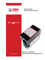
thyro
switch
System | english
Thyristor switch for
reactive current compensation
© KBR GmbH
Subject to
technical changes
2
Contents
EDEBDA0200-2112-1_EN
Intended use .................................................................................................................. 4
Safety Notes ................................................................................................................................................ 6
Application range ..................................................................................................................................... 7
Installation ................................................................................................................................................... 8
Connection . ................................................................................................................................................. 9
Start-up ......................................................................................................................................................... 10
Performance limitation depending on ambient temperature ........................................... 11
Model type overview .............................................................................................................................. 11
Declaration of conformity .................................................................................................................... 11
V2.0
3
thyro
switch
1 Intended use
The thyroswitch is a power electronics component for hooking up capacitive loads to
the grid. The device is intended exclusively for installation in switchgear and controlgear.
Only detuned (up to 14 %) compensation stages may be switched. First and foremost,
symmetrical three phase current compensation is the intended use, but it is also possible
to switch two separate alternating current compensation stages simultaneously.
Technical data:
Input:
- Control input
- Fusing
typically 10V DC-10mA / 30V DC-22mA
typically 180V AC-10mA / 260V AC-14mA, 50/60Hz
max. 6A
Power supply:
- Auxiliary voltage
85-265V AC/DC 14VA 50/60Hz
no tolerance in either direction
- Fusing
max. 6A
Load circuit:
- Supply voltage UN
400/500V 50/60Hz depending on type
- Tolerance UN
UN±10
- Harmonic voltage
acc. to DIN EN 61000-2-4 class 3; THD max. 10%
- Load current:
70/90/115A depending on type
- Power dissipation
70A type approx. 2.2W per A
90/115A type approx 2.1W per A
For power-off time > 5s
Closure delay:
Input:
Reclosure delay:
- DC: 0 … max. 20ms
- AC: 10 … max. 30ms
at chopping operation
Input:
- DC: 0 … max. 33ms
- AC: 10 … max. 43ms
EDEBDA0200-2112-1_EN
Electrical safety:
Standards and subsequent amendments
- Protection class
I
- Protection type
IP10
- Overvoltage category
CAT3
4
V2.0
thyro
switch
Ambient conditions:
- Standards and
subsequent
amendments
DIN EN 60721-3-3/A2
(3K5+3Z11)
IEC 721-3-3 (3K5+3Z11)
- Operating temperature
-5°C... +55°C => Please observe power limitation
depending on ambient temperature (see page 8).
- Air humidity
5%...95% non-condensing
- Storage temperature
-25°C... +70°C
Installation:
- Position
vertical (recommended) or 45° tilted
- Space for heat discharge
at least 50 mm to the fan
and at least 150 mm to the heat sink outlet
Housing:
70/90A-Typ: 220 x 105 x 188 mm
(H x W x D)
115A-Typ:
Weight:
70/90A-Typ: approx. 2900 g
115A-Typ:
220 x 105 x 198 mm
EDEBDA0200-2112-1_EN
approx. 3600 g
V2.0
5
thyro
switch
2 Safety note
Due to the design with forced cooling, i. e. with the use of a fan, particularly the unimpeded
air intake must be guaranteed. The cooling openings must not be covered up. The distances
specified from neighboring components must be observed.
For rated load, there is an increase in temperature between fresh air and exhaust air of:
• max. 52°C for type 115A
• max. 40°C for type 90A
• max. 35°C for type 70A
Temperature-sensitive components such as cable ducts should be protected accordingly.
The thyroswitch may only be operated with a power disconnecting device connected in
series.
The thyroswitch cannot function alone as a component and must be configured for use
with a compensation unit.
In detuned systems, it is absolutely essential that the thyroswitch is switched before the
inductor and capacitor.
The thyroswitch may only be deployed in the context of its intended use.
Even when used only as intended, a defect cannot be ruled out. In this case, the currents
and voltages in the load circuit could be affected. The following errors are possible: Current
interruption, half-wave operation or constant energy flow. Correct design of protective
devices must therefore be ensured during project planning.
Incorrect operation or wrong connections could lead to destruction of the device or the
load.
Work such as assembly, maintenance and servicing may only be performed by qualified
electricians. A soon as the thyroswitch is connected to the power supply system, the
capacitive load is charged to to network peak voltage. In addition, a phase is switched
directly to the load. This means that the load is under voltage, even when switched off, and
remains connected to the power supply. When working on the load, the device must be
disconnected from the power supply under all circumstances. Risk of fatal injury!
6
V2.0
EDEBDA0200-2112-1_EN
The thyroswitch may only be connected with insulated crimp-type cable sockets.
thyro
switch
Even after disconnection from the network, a residual charge remains in the capacitive
load. Before working on the equipment, it must be checked that the capacitors are deenergized. The discharge time of the capacitors must be taken into account.
Note: Power capacitors must be equipped with permanently connected discharge devices
and be discharged within five minutes to a residual charge of max. 50µC to a voltage of
60V. If this has a disturbing effect on the function of the electrical equipment, a warning
sign must be put up in a clearly visible position stating that the discharge time is longer
than five minutes. If it is possible to come into contact with the voltage of the capacitors
even if the connectors are used correctly, and if these connectors can be pulled off without
the use of tools, the discharge must be possible within one minute. (See EN 50178, section
5.2.5)
For the setup of the discharge equipment it must be remembered that capacitors when
switched off are charged to a direct voltage at the level of the network peak voltage.
The parallel operation of systems with conventional protective relaying and semiconductor
technology is only possible for induced systems. Otherwise, the thyroswitch could be
destroyed by charging effects.
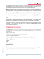
3 Application range
The thyroswitch is particularly intended for systems with frequent and rapidly changing
reactive power loads. The advantages of the thyroswitch compared to conventional
technology are:
• High switching speed
• Switching performance with low system perturbation
• Switching without wearing parts
• Long working life thanks to practically unlimited frequency of operations
Fields of application:
• Cranes
• Lifts
• Welding equipment
• Molding presses
EDEBDA0200-2112-1_EN
• Wind turbines
The power switch can be operated in conjunction with reactive power controllers,
programmable logic controllers, computer systems and process controllers.
V2.0
7
thyro
switch
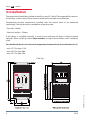
4 Installation
The thyroswitch should be installed vertically or max. 45° tilted. The integrated fan controls
the air flow, so that nearly all the warm air produced is emitted in one direction.
Temperature-sensitive components installed near the device have to be protected
accordingly. The safe distances specified must be observed.
• Fan side: >50mm
• Heat sink outlet: >150mm
If the device is installed vertically, it must be ensured that the heat is always emitted
upwards. When installing several thyroswitches on top of one another, cowls should be
used.
For rated load, there is an increase in temperature between fresh air and exhaust air of:
• max. 52°C for type 115A
• max. 40°C for type 90A
• max. 35°C for type 70A
EDEBDA0200-2112-1_EN
115A-Typ
8
V2.0
thyro
switch
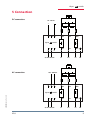
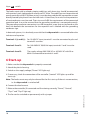
5 Connection
10 - 30V DC
DC connection:
_
+
10 - 30V DC
_
+
thyro
thyro
AC connection:
1
2
3
U2
V2
W2
1
2
3
U2
V2
W2
4
5
6
U1
V1
W1
4
5
6
U1
V1
W1
switch
switch
85-265 VAC/DC
L1
L2
L3
PE
85-265 VAC/DC
L1
L2
L3
PE
180 - 260V AC
180 - 260V AC
EDEBDA0200-2112-1_EN
thyro
thyro
V2.0
1
2
3
U2
V2
W2
1
2
3
U2
V2
W2
4
5
6
U1
V1
W1
4
5
6
U1
V1
W1
switch
switch
85-265 VAC/DC
L1
L2
L3
PE
85-265 VAC/DC
L1
L2
L3
PE
9
thyro
switch
The load current with insulated crimping cable lugs with 8mm rings should be connected
with terminal studs, tightened with a torque of 5.5 - 6Nm. The cable lugs must be positioned
exactly vertically to the PCB. When wiring, it must be observed that the connections are not
directly heated up by the air from the heat sinks. As load fuses, fuse units for the protection
of semiconductors must be used. Their size must fulfill the requirements of the connected
capacitive load. It must be ensured that the grounding conductor is connected correctly.
The grounding conductor connection is an M6 hexagonal screw that can be found on the
heat sink beneath the connections for the capacitor and is labeled with the grounding
conductor sign.
In detuned systems, it is absolutely essential that the thyroswitch is connected before the
inductor and capacitor.
Terminals 1(+) and 3(-):For 10-30V DC input, terminal 1 must be connected to plus and
terminal 3 to minus.
Terminals 2 and 3:For 180-260V AC 50/60 Hz input, terminals 2 and 3 must be
used.
Terminals 4 and 5:The supply voltage 200-250V AC or 85-265V AC with 50 or
60Hz is connected to terminals 4 and 5.
6 Start-up
1. Make sure that the thyroswitch is properly connected.
2. Attach the plastic housing.
3. Switch on the supply voltage ("Power" LED lights up)
4. If necessary, check the connection of the controller ("control" LED lights up and fan
starts up).
Note: The load current may only be released for the first start-up if there is no connection,
i. e. the thyroswitch is switched off.
6. Connect the load current.
7. Release the controller (if connected and functioning correctly, "Power", "Control",
"Thyr1" and "Thyr2" light up).
EDEBDA0200-2112-1_EN
8. The fan can be switched on permanently with a jumper.
10
V2.0
thyro
switch
Strom [A]
7 Performance limitation depending on
ambient temperature
Umgebungstemperatur [°C]
8 Model type overview
Special voltages and currents on request
9 Declaration of conformity
EDEBDA0200-2112-1_EN
ENGLISH
CE DECLARATION OF CONFORMITY
We declare that we have sole responsibility that this product (see table) meets the
conditions of Directives 73/23/EEC and 89/336/EEC and corresponds to the following
standards or reference documents:
EN 61010-1:2002-08; EN61010-1/B1:2002; EN 61010-1/B2:2004;
EN 61000-6-1:2007; EN 61000-6-2:2005; EN 61000-6-3:2007; EN 61000-6-4:2007
V2.0
11
Am Kiefernschlag 7
D-91126 Schwabach,
Germany
Phone +49 (0) 9122 6373 - 0
Fax
+49 (0) 9122 6373 - 83
E-mail [email protected]
www.kbr.de
EDEBDA0200-2112-1_EN
KBR Kompensationsanlagenbau GmbH