1
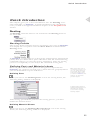
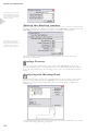
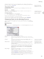
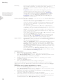
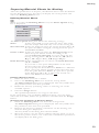
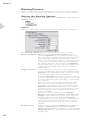
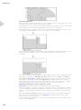
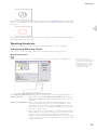
Infinum
Nesting
User Manual
Align: y
Intersection
Align: x
Infinum
Nesting-Handbuch
Manual version: I40U5Ge05
May 2005
Development: Concepts Technology Co. Ltd.
Documentation:
Infinum, DraftBoard and the Slogans The smart Drawing Board
und The smart Drawing program are trade marks of
Concepts Technology Co. Ltd.
Other trademarks and product names are trademarks and registered
trademarks of their respective holders.
© Copyright 2005, Concepts Technology Co. Ltd. All rights reserved..
Tabel of Contents
First Steps
7
Documentation ........................................................................... 7
Registration .................................................................................. 7
System Requirements ................................................................. 8
Installation ................................................................................... 8
Starting Infinum ......................................................................... 8
Quick Introduction
11
Nesting ....................................................................................... 11
Nesting
15
Constructing Parts and Sheets ................................................ 15
Nesting Tools ............................................................................ 16
Defining Parts and Material Sheets ........................................ 16
Nesting Process ........................................................................ 20
Nesting Analysis ....................................................................... 23
CHAPTER
1
First Steps
Documentation
Registration
System Requirements
Installation
StartingInfinum
First Steps
1
First Steps
This manual describes how to use Infinum on your computer.
The Getting Started chapter briefly describes the documentation of Infinum, tells you how to install the program on your computer and use
it with Microsoft Windows. It lists the type of equipment you need, tells
you how to register your copy of Infinum and tells you how to start
and end Infinum..
Documentation
This manual describes Infinum for Windows 98/ME, Windows 2000,
Windows NT4 SP5 and for Windows XP.
Infinum consists of the following two parts
•
Nesting
and
• Construction
that are both integrated into one program, but are described in two
manuals.
Detailed informations about
the user interface of your
computer you find in the
User Guide for Microsoft
Windows .
The documentation of Infinum consists of the following Nesting
manual and, since the drawing tools of Infinum are identical with
DraftBoard Professional, the User manual of DraftBoard
Professional.
Before using this manual, you should install Infinum on your
computer. Installation instructions are contained in this chapter.
After installation you should study the Quick Introduction chapter in the
DraftBoard manual first and then continue with the chapter Nesting
Techniques in this Infinum manual. This will familiarize you with the
tools, features and commands of Infinum and enable you to maximize your productivity in the shortest amount of time.
Registration
Contrary to popular opinion, registration cards and trash aren't
synonymous. In fact, the registration card for Infinum, conveniently
located inside your software box, is quite valuable – to you and to us.
We'd really like to encourage you to return it. Filling out the
registration card is a painless process.
For such a minor investment of time, you'll become a registered
customer . Only by registering Infinum, are you entitled to receive
Telephone product support and Free updates
7
First Steps
System Requirements
The system requirements for Infinum are identical with the den
system requirements for DraftBoard Expert and listed in the
enclosed DraftBoard manual. In addition Infinum requires a dongle
for launching the program.
1
Installation
Important: Before you start
the installation remove any
USB Dongle from the USB
Interface. Dongles for a
Parallel-interface must not
be removed.
Infinum comes on a CD-ROM and can be installed as a Single User
License for Microsoft Windows.
Single User License
The Single User License will be installed as follows.
Installing a Single User License for Windows
1.
Start Microsoft Windows.
2.
Insert the Infinum CD ROM into the CD ROM drive of your
computer.
Start the Explorer
3.
4.
In the Explorer click on the icon for your CD ROM drive.
The content of the CD ROM is displayed.
5.
Start the installation by double clicking the file Setup.exe.
6.
Follow the directions on the screen.
7.
During the installation you are asked to enter your Authorization Code, that you will find on the enclosed License Agreement.
After the installation Infinum 4.0 is displayed in the WindowsStart menu.
When the installation is complete, click the OK button.
The installation automatically creates the submenu Infinum 4.0
in the Program menu of the Windows Start menu.
This menu contains besides other entries the menu item
8.
Infinum 4.0
that will start Infinum.
You should read the Read me file first that you can open with the
Readme menu item, since it contains information that was not
available when this manual was printed.
Starting Infinum
You start and quit Infinum as follows:
1.
2.
3.
Connect the enclosed Dongle to the parallel or USB interface of
your computer. If you want to connect your computer to a printer
using the parallel interface, the printer cable can be connected
directly to the dongle.
Start your computer.
Select the menu item
Infinum 4.0
in the Infinum 4.0 submenu in the Start menu.
Terminating Infinum
1.
2.
8
Click File in the Infinum menu bar.
The File menu is displayed.
Select the menu item Quit in the File menu.
CHAPTER
2
Quick Introduction
Overview of the Nesting functionality of Infinum
Quick Introduction
2
Quick Introduction
This chapter gives you a short introduction into the Nesting tools
and commands of Infinum. A quick introduction into the drawing
tools you find in the Quick Introduction chapter of the DraftBoardManual.
Nesting
All Nesting commands and tools are situated in the Nesting menu in
the menu bar.
Nesting Palette
The Nesting Palette contains all tools required to nest parts in Infinum.
You display the tool palette with the Show Palette command in the
Nesting menu.
In Infinum you first import or design the required parts and material
plates, then you define these parts and sheets with the related Nesting
commands, before you start the nesting calculation. After the nesting
process is completed you can analyse the calculated nesting data.
Defining Parts and Material sheets
When all parts and material plates are designed or imported into
Infinum, the geometry of each part or sheet must be grouped, before
you can define them as parts and sheets.
Defining Parts
Objects that exist only of
one element such as a circle or an ellipse must not
ne grouped. That is valid
as well for symbols, that
you plave in Infinum , since
symbols are placed as
grouped objects.
When you choose the Defining Parts tool in the Nesting Palette, the
following dialog window is displayed:
A detailed description for
defining Nesting Parts you
will find in the related
section in the following
Nesting chapter.
After having specified the parts for the nesting process, you must
define the material sheets. .
Defining Material Sheets
When you choose the Defining Material Sheets tool in the Nesting
Palette, the following dialog window is displayed:
11
Quick Introduction
A detailed description for
defining Material Sheets
you will find in the related
section in the following
Nesting chapter.
2
Setting the Nesting options
Before you can start the nesting calculation, you have to specify all
nesting parameters. When you select the Options command in the
Nesting menu the following dialog window is displayed:
A detailed description for
specifying the Nesting
Options you will find in the
related section in the following Nesting chapter.
After you have specified all Nesting Options you can start the
Nesting calculation.
Nesting Process
For the Nesting calculation you select the Nesting tool in the
Nesting Palette. This command nests automatically and according
to your specifications all existing parts onto the defined material
plates.
Analysing the Nesting Data
When the nesting process is completed you can analyse the calculated nesting data using the Result tool in the Nesting Palette.
When you select this command the following dialog window is
displayed:
A detailed description of all nesting tools and commands you find
in the following Nesting chapter.
12
CHAPTER
3
Nesting
Introduction
Defining Parts
Defining Plates
Nesting Process
Analysis
Nesting
3
Nesting
With Infinum you purchased a powerful Nesting program. It provides
interactive and automatic nesting of an infinite number of shaped parts
on any number of sheets.
You can import parts or design them within Infinum. The powerful
integrated CAD engine offers all professional tools such as for Splines
or Offset Curves for constructing parts and designing material sheets.
After the definition of parts and material sheets and the specification
of all related Nesting parameters such as Collarwidth, Cutter Diameter,
Clearance etc., Infinum calculates in an one step process the optimized
arrangement of the defined parts on all specified sheets.
An Analyze tool provides precise data of the optimization process. The
results can be exported as ASCII Data.
Introduction
The Nesting process in Infinum requires the following steps:
•
Construction or Import of parts and material sheets.
•
Defining parts and sheets.
•
Nesting.
[Calculation of the optimum arrangement of the placed parts]
•
Nesting Analysis.
[Evaluation of the calculated data].
Before you can nest the parts you must first design the parts or import
them into Infinum..
Constructing Parts and Sheets
Infinum has an integrated CAD Engine for the construction of
nesting parts and material sheets.
15
Nesting
For the construction of parts and sheets you can use all in Infinum
available geometry elements such as
How to use the different
tools is decribed in the
DraftBoard manual that
explains all CAD commands and functions,
that are integrsated into
Infinum .
3
•
•
•
•
•
•
•
•
•
Lines
Connected Lines
Parallel Lines
Offset Curves
Arcs
Circles
Ellipses
Polygons
Spline Curves
The related tools for constructing these geometry objects you find in
the Tool palette located at the left side of the Infinum window.
A precise description of
the Import command you
find in the DraftBoard User
Manual . When you select
the Group option while
importing you don’t have to
group the geometry again
after having it imported.
Instead of designing parts and sheets you can import any type of
geometry into Infinum that was created in other CAD or Graphic
programs using the Import command in the File menu.
When you have designed the parts you must group all geometry
elements using the Group command in the Arrange menu. That is not
required for elements that exist of one entity like circles, ellipses or
symbols that are already grouped when you place them into Infinum .
After having designed or imported and grouped all parts, they must be
defined as parts and sheets for the nesting process..
Nesting Tools
All commands and functions for Nesting you find in the related menus
in the menu bar.
All Nesting commands and tools you find in the Nesting menu in the
menu bar.
When you select the Show Palette command the Nesting Palette is
displayed.
Nesting Palette
The Nesting palette contains all functions required for nesting in
Infinum.
Show Palette
This command displays the Nesting Palette:
This type of command is
called a Toggle command
since it toggles between
the two command Show
Palette and Hide Palette
depending if the Nesting
Palette is displayed or not.
For removing the Nesting Palette you select the Hide Palette command
in the Nesting menu. The Nesting Palette can be moved on the drawing
area and is handled like the DraftBoard Tool Palette. The Nesting
Palette contains the following functions:
All functions are described in the next sections.
Defining Parts and Material Sheets
After you have all parts and sheets designed or imported into
Infinum, all geometry objects must be grouped, before they can be
specified as Nesting Parts or Nesting Sheets.
16
Nesting
Objects that exist only of one entity like circles, ellipses must not be
grouped. That is also valid for symbols that are already grouped when
they are placed in Infinum.
Grouping Parts
More information about
Symbols you find in the
Symbols chapter of the
DraftBoard User Manual .
Geometry elements are grouped using the Group command in the
Arrange menu.
Group
Ctrl+Y
This command in the Arrange menu combines selected objects to
function as a single object.
Grouping Objects
1.
Select the objects to be grouped..
2.
Select Group from the Arrange menu.
A detailled description of
the Group command you
find in the Edit Objects
chapter of the DraftBoard User Manual .
Once you group geometry, you can’t edit the individual objects
within the group unless you ungroup them.
You can also combine groups. For hierarchical groups, Infinum
ungroups each group in the order in which they were combined.
Preparing Parts for the Nesting Process
After having grouped all parts the must be defined for the Nesting
process. To do so we display the Nesting Palette and select the Defining
Parts tools.
Defining Parts
When you select the Defining Parts tool the Part Options dialog box
is displayed:
This dialog box allows the following settings:
Name
In this entry field you can name the part. The name
must be unique and may exist only once in the nesting
file.
Target
This entry field requires the target number and
specifies how often you want to nest that part on all
defined material sheets.
Filler Parts
In this entry field you enter the quantity of so called
Filler parts that should be nested in addition to the
Target quantity in case there remains enough room
on the sheets.
Independent of the target
quantity specified, Infinum
can only nest as many
parts as there is space on
the defined sheets. The
actusal number of parts
finally nested is shown in
the Nesting Results dialog
box.
In case you have defined several sheets, the parts are
only nested on sheet that contain already parts. For
placing Filler parts you must choose the option Fit
Filler Parts on last Sheet in the Nesting Options
dialog box.
Step Angle
In this entry field you can specify the desired Step
Angle from 0° to 360°.
When calculating the arrangement of the parts on a
sheet, Infinum will rotate the parts around their
center to find the optimum placement. The number of
degrees Infinum is allowed to rotate the parts is
specified in this entry field. The smaller the specified
step angle the longer the calculation process will last.
The default step angle is 90°.
17
3
Nesting
Priority
In this entry field you specify the priority a part should
be nested in relation to other parts. The priority is
defined in whole numbers where 1 specifies the lowest
priority.
Infinum places a part with the highest priority
number before all other parts on the first sheet.
In case parts have an identical priority, Infinum
checks the sorting parameters (Perimeter or Area)
you have set in the Nesting Options dialog box.
Infinum will nests than the part with the largest
perimeter or area first.
Setting the Nesting options
in the section Nesting Process provides a more detailed description about the
options Perimeter/Area.
3
Grain direction In this List Field you can choose the Grain direction
(X, Y or None).
If you want to nest a part independent of the Grain
direction, select the option None.
You can select a specific Grain direction (X or Y) only,
if you have also defined a specific Grain direction for
the Material sheet.
If a specific grain direction (X or Y) is defined for
parts, but not for the Material Sheet (Grain direction
= None), the parts will not be nested.
Note: If a specific grain direction (X or Y) is defined for
parts, it also must be defined for Material Sheets, Only then
the parts will be nested.
Parts with specific grain direction (X or Y) will not be nested
on sheets with none grain direction..
In case parts and material sheets have specific grain
directions (X or Y), Infinum will rotate all parts to
match the grain direction of the related sheets.
Type of Fit
In this list field you can select if Center of Gravity or
Quicktest (Area) should be the determining parameter
for the nesting calculation.
With the Quicktest (Area) option the nesting process
will be significantly faster than with the Center of
Gravity option. Though the nesting calculation with
the Center of Gravity option is slower, it may lead to
better nesting results, especially if the parts have very
irregular shapes.
If you select in the Nesting Option dialog box the
Flat End method, Infinum will automatically switch
to the Center of Gravity option.
Defining Parts
1.
Select the part you want to define.
2.
Choose the Defining Part tool from the Nesting Palette.
The Parts Option dialog box is displayed. The entry fields show
the parameters that were last-specified.
3.
Define the part by specifying values or selecting one of the
available options.
4.
Click the Assign button.
The specified parameters are assign to the part.
In the open dialog you can define additional parts. You just must
select the next part, define the parameters and click then the Assign
button.
Checking the assigned Parameters of Parts
18
1.
Select the Defining Part tool from the Nesting Palette.
The Parts Option dialog box is displayed. The entry fields show
the parameters that were last-specified.
2.
Deselect all objects by clicking somewhere on the drawing area
with the dialog box displayed.
All entry fields in the dialog box will turn blank.
3.
Move the mouse over the parts without selecting them. As soon
the mouse pointer comes over a part the related part parameters
are displayed in the Part options dialog window.
Nesting
Preparing Material Sheets for Nesting
After the specification of all parts, the Material sheets must be defined
for the Nesting Process. For that you display the Nesting Palette and
select the Defining Sheets tool.
Defining Material Sheets
When you select the Defining Sheets tool, the Sheets Option dialog
box is displayed:
3
The Sheets option dialog box allows the following settings:
Name
In this entry field you can name the sheet. The name
must be unique and used only once in the nesting file.
Nest direction In this list field you select the Nesting direction (X or Y)
the parts should be arranged, starting from the specified Corner to Start.
Corner to Start In this list field you select the Starting Corner from
where the parts will be nested according to the
specified Nesting direction. You can select the following starting points: LL (Lower Left), LR (Lower
Right), UL (Upper Left), UR (Upper Right).
Grain direction In this List Field you can choose the Grain direction
(X, Y or None).
If you want to nest parts independent of the Grain
direction select the option None.
If you specify the Grain direction None for a Material
Sheet, only parts will be nested on that sheet that also
have the grain direction None. If a part has a specific
Grain direction (X or Y), it will not be nested on a
sheet with None Grain direction.
Defining Material Sheets
1.
Select the sheet you want to define.
2.
Choose the Defining Sheet tool from the Nesting Palette.
The Sheets Option dialog box is displayed. The entry fields show
the parameters that were last-specified.
3.
Define the sheet by specifying values or selecting one of the
available options.
4.
Click the Assign button.
The specified parameters are assign to the sheet.
In the open dialog you can define additional sheets. You just must
select the next sheet, define the parameters and click then the Assign
button.
Checking the Parameter of Material Sheets
1.
Select the Defining Sheet tool from the Nesting Palette.
The Sheet Options dialog box is displayed. The entry fields show
the parameters that were last-specified.
2.
Deselect all objects by clicking somewhere on the drawing area
with the dialog box displayed.
All entry fields in the dialog box will turn blank.
3.
Move the mouse over the sheets without selecting them. As soon
the mouse pointer comes over a sheet the related sheet parameters
are displayed in the dialog box.
19
Nesting
Nesting Process
Before we can calculate the arrangement of the parts on the material
sheets, we have to specify the general options for the Nesting Process.
Setting the Nesting Options
To set the Nesting options you must select the Options command in the
Nesting menu.
3
Options
When you select this command the following dialog box is displayed:
The Nesting options dialog box allows the following settings:
Flat end method
When the option Flat end method option is
selected, Infinum tries to place the parts along
the nesting direction with a minimum material waste
(epitomised for minimum sheet length) and to
create a flat end. This is done by rotating the parts
in a way that the smallest side of a part shows in
the nesting direction. At the sheet end Infinum
arranges the parts to create a flat end. This option
is important especially when parts are nested on
endless sheets.
Height fraction
In this dialog box you specify a percentage value
of the overall nesting sheet length required, where
Infinum will switch from Center of Gravity nesting
to the Minimum length (flat end) method.
Normally Infinum optimizes the parts according
to their Center of Gravity, in the opposite to the Flat
end method that nests parts according to their smallest extension.
Since the Center of Gravity nesting requires often
less material, you can combine both methods by
specifying a percentage value for the sheet length..
Infinum then will nest parts below that value
according to their Center of Gravity and above that
value according to their minimum extension to
create a flat end.
The best results you will get with a Height
fraction between 60 % and 80 %. With 100 % Infinum would exclusively use the Center of Gravity
method with no flat end. With 0 % Infinum
would exclusively use the Minimum Length method
with a flat end, but the material waste could be
significantly larger than with the Center of Gravity
method.
Fit Filler parts
20
If that option is activated, Infinum will nest the
number of Filler Parts specified in the Parts
options dialog window in addition to the specified
Target Quantity on all sheets that contain already
nested parts.
Nesting
On all empty sheets that were not required to nest
the specified Target Quantity no Filler parts will
be nested.
If the Fit Filler parts option is not activated
Infinum will nest only the Target Quantity
specified in the Parts options dialog window.
Resolution
This value specifies the Nesting Resolution. The
smaller the resolution the more compact the parts
are nested, but will require more time to calculate
the nesting.
Remember: The option Fit
Filler Parts never will start
a new sheet to fill exclusively filler parts.
The smallest value allowed is 0,001 mm. The
largest value must be larger than the length of the
longest sheet divided by 50 000.
3
If the resolution is larger than this value no
nesting will occur. Recommended is the default
value 1.
Cutter diameter
In this entry field you enter the Cutter diameter
of the cutting tool you will use later to cut the
nested parts.
Clearance
Here you specify the Clearance between two
parts. For the absolute clearance between two
parts you must add twice the cutter diameter (for
each part).
Collar width
With this value you define the minimum distance
Infinum should keep from the sheet edge.
Sort by
In this list field you define according to which
parameter Infinum will place parts of equal
priority: First parts with the largest area or parts
with the largest perimeter.
Color to ignore
In this list field you can choose a color for
geometry objects that Infinum will ignore during
the nesting calculation. More information about
this option you will find in the next section Nesting
Calculation.
Nesting Calculation
Infinum offers the following Nesting functionality:
•
True Shape Nesting
Parts with irregular shapes are nested in a way that other parts can
use the cutout of these parts.
•
Multilevel Nesting
Holes and cutouts can be nested with smaller parts to achieve a
minimum material waste.
•
Multiple Orientation
Infinum rotates parts for an optimized arrangement by 1° steps.
•
Non-rectangular Plates Support
Infinum is able to nest parts at any shape.
The Nesting calculation in Infinum is a fully automatised process,
that starts as soon you select the Nesting tool in the Nesting palette.
Nesting
When you select this tool all parts will be nested fully automatically
according to the specified parameters. If a nesting calculation is not
possible, an error message will be posted.
Center of Gravity Nesting
With this nesting option all parts will be nested on any sheet according
to their Center of Gravity.
21
Nesting
Flat End Nesting
This Nesting option is design to nest endless sheets targeting for a flat
end and use the minimum sheet length possible.
3
The default Center of Gravity nesting method normally uses less material
but requires more sheet length and won't create a flat end.
In the following graphic you see a optimized arrangement of parts on
an endless sheet nested by the Center of Gravity method.
The following graphic shows the same example nested by the Flat end
method. There could be more material used than in the previous
example.
The best result you will achieve with endless sheets by combining both
methods and using a Height fraction value between 60 % and 80 %.
With 100 % Infinum would exclusively use the Center of Gravity method with no flat end. With 0 % Infinum would exclusively use the
Minimum Length method with a flat end, but the material waste could
be significantly larger than with the Center of Gravity method.
Ignoring geometry with a specific color
Infinum interprets all closed shapes as part boundaries.
If for example a geometry object contains a circle, that doesn't present
a part boundary (cutting boundary) it will be only ignored by nesting
and not interpreted as a hole, if you assign this geometry an ignoring
color.
But the Color to ignore option can not be used to exclude complete
parts from nesting. In this case Infinum would generate the error
message No closed Geometry!
In the following example a part has a rectangular outer boundary with
a hole in the middle.
22
Nesting
When you assign the circle an ignoring color, Infinum will handle this
part as a rectangular shaped part and will not place smaller parts within
the hole.
3
Notations within and assigned to parts will be automatically identified
and ignored while nesting.
Nesting Analysis
After parts have been nested the calculated data can be analyzed.
Analyzing Nesting Data
The tool for the Nesting analysis you find in the Nesting Palette.
Nesting Results
When you select this tool the following dialog window is displayed:
The units of all areas
displayed correspond to the
units selected in the Units
dialog box, that you find in
the Preferences submenu
of the Layout menu. The
default value is mm 2 .
The Nesting Results dialog box contains the following Information:
Parts/Sheets
With this option NstSheets/NstParts you select
if Parts or Sheets will be displayed in the Selection
Window.
Selection Window The Selection Window displays depending on the
option selected all parts or sheets listed in a tree
structure. If you click on the + sign in front of a
list item the tree is expanded displaying all objects
related to that item.
Each tree item is followed by a number in brackets
that indicates how often that part is nested on all
sheets. If two numbers are displayed the first
number represents all defined parts (Target Quantity
+ filler parts) and the second number shows nested
Target quantity.
23
Nesting
Assumed you have selected the Sheet option and
you click on the plus sign in front of a sheet, than
all parts will be displayed that are nested on that
sheet.
If you have selected the Part option all sheets will
be listed where the selected part was nested.
Result Window
Sheet Option
The Result Window lists all calculated nesting data
of a part or sheet that is selected in the Selection
Window:
Sheets selected in the Selection Window:
Nested Parts
Here you find the number of different parts that
were nested on that sheet.
3
Sheet Area
shows the whole area of the selected sheet.
Nested Area
lists the summarized area of all parts nested on the
selected sheet.
Used Area
shows the used area of all nested parts on that
sheet including the specified Clearances and Cutter
diameters in the Parts options dialog box.
Usage (%)
shows how many percent of the area of the
selected sheet is used.
Parts selected in the Selection Window:
Target Quantity
shows the quantity specified in the Parts options
dialog as Target Quantity for that part.
Nested
shows how often this part is nested on all sheets
including all possible filler parts.
Nested on sheet ‘Name’
shows how often the selected part is nested on the
selected sheet.
Part Option
Part selected in the Selection Window
Target Quantity
shows the Target Quantity defined for that part
in the Part Options dialog box.
Nested
shows how often the selected part is nested on all
sheets including any filler parts.
Remaining Quantity
shows how many parts of the Target Quantity
were not nested. This number does not include
any Filler Parts.
Used Sheets
shows on how many sheets the selected part was
nested.
Sheets selected in the Selection Window
Target Quantity
shows the Target Quantity for that part specified
in the Part Options dialog box.
Nested
lists how often the related part is nested on the
selected sheet including any possible Filler Parts.
Nested on sheet ‘Name’
shows how often the selected part is nested on the
selected sheet.
View
24
When you select this option the View window is
displayed showing the selected part or sheet.
Nesting
Export
When you click this button the Save as dialog
window is displayed, where you can specify a name
for the data you want to export. As soon as you
click the Save button all Nesting Results are saved
as ASCII File.
Show
When you click this button the selected part or
sheet is selected on the drawing area and displayed
at full screen size.
3
25