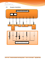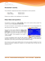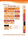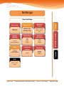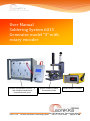
1
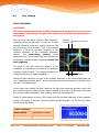
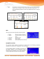
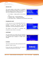
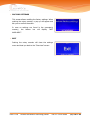
User Manual Soldering System 6015 Generator model “S” with rotary encoder soniKKs Sonobonders US 6015 – R with Profibus interface and handheld control panel 2014-07-28 soniKKs Soldering Station for laboratory trials soniKKs Ultrasonics Technology GmbH soniKKs Heater Controller Doc.nr.: 3010.2399a page 1 of 39 Table of contents Table of contents ................................................................................................................. 2 Safety ................................................................................................................................. 4 1. Conventional use .......................................................................................................... 4 2. Security instructions...................................................................................................... 5 3. Device Placement ......................................................................................................... 6 Packages ............................................................................................................................. 7 Technical Data ..................................................................................................................... 8 Cabling description ............................................................................................................... 9 1. Connectors overview ..................................................................................................... 9 2. “Interface” connector .................................................................................................. 11 2.1. Pin-out ................................................................................................... 11 2.2. Description of the signals ......................................................................... 12 2.3. Example of installation............................................................................. 13 Status LEDs ....................................................................................................................... 14 Parameters’ security ........................................................................................................... 14 Menu items and operation ................................................................................................... 15 Navigation chart ................................................................................................................. 16 Structure of the menu and functions .................................................................................... 19 1. Overview ................................................................................................................... 19 2. Time & Energy ........................................................................................................... 19 3. Solder. Tip Temperature ............................................................................................. 19 4. Power ........................................................................................................................ 20 5. Frequency .................................................................................................................. 20 6. Timer ........................................................................................................................ 20 7. Energy ....................................................................................................................... 21 8. Display ...................................................................................................................... 22 9. Setup ........................................................................................................................ 22 9.1. User settings .......................................................................................... 23 9.2. Reseller settings...................................................................................... 27 Operating instructions ......................................................................................................... 31 1. Introduction to the ultrasonic soldering process ............................................................ 31 2. Standard soldering procedure ...................................................................................... 31 3. Changing heaters and sonotrodes ................................................................................ 32 2014-07-28 soniKKs Ultrasonics Technology GmbH Doc.nr.: 3010.2399a page 2 of 39 Troubleshooting ................................................................................................................. 35 Maintenance and care ......................................................................................................... 37 Warranty ........................................................................................................................... 37 Declaration of Conformity.................................................................................................... 38 Imprint .............................................................................................................................. 39 2014-07-28 soniKKs Ultrasonics Technology GmbH Doc.nr.: 3010.2399a page 3 of 39 Safety Below you can see all the warning and security symbols used in this manual. Symbols in this manual: Immediate danger to health and life (bad injuries or death). Attention hot surface. Do not touch! Possible damage, without danger for people. Electrical voltage! Symbols on the devices: CE Conformity Symbol Attention hot surface. Do not touch! (on the soldering iron and the soldering station) 1. Conventional use This generator was designed to be used in ultrasonic soldering applications. Using a proper solder alloy from the CERASOLZER family, various materials can be soldered (e.g. ceramic, glass, metals…). 2014-07-28 soniKKs Ultrasonics Technology GmbH Doc.nr.: 3010.2399a page 4 of 39 This generator can only be used with soniKKs components (i.e. ultrasonic soldering iron, foot switch and other accessories). We cannot guarantee the compatibility and the good functioning of third party manufacturers’ components. 2. Security instructions Operations of all ultrasonic equipment by trained staff only! Do not use this unit in explosive environments without taking all necessary security measures! Check the unit any time before operating. The electromagnetic compatibility conforms to international standards. For more details, consult the “Technical data” section of this manual. All necessary adjustments are either made by the manufacturer or described in this manual. In case of any trouble with the generator, do contact our technical service. Never open the unit or, in any way tamper with it. This will void your warranty and may cause an electric shock. For any cleaning or maintenance of the device, please disconnect the mains supply. All maintenance should be done by trained staff only. Pay attention to all warnings and hints in this manual and on the generator. Great attention should be given to the mains supply voltage. Over- or undervoltage can cause malfunction or destroy the generator! Always place the generator on a stable and flat surface. Correct operations can only be guaranteed if the generator is used along with the recommended ultrasonic iron. Use only the recommended interface cables. Do not coil up the RF-cable or the line cord. Coiling up these cables can cause overheating of the cables. While using the generator, do not touch the heater or the soldering iron’s shaft. Caution – could be very hot! Never point the connected soldering iron at people. Avoid all operations of the generator in presence of animals. They have a more extended frequency range of audible sound than people and are thus highly sensitive to ultrasounds. ATTENTION ! 2014-07-28 Be careful when manipulating the soldering iron and the soldering station while in use. Do not ever lay the soldering iron on a table or near any flammable item or substance. Danger of fire. soniKKs Ultrasonics Technology GmbH Doc.nr.: 3010.2399a page 5 of 39 In the following cases, immediately disconnect the unit from the mains and call a qualified service technician: 3. If If If If If cables or connectors are damaged the housing is damaged fluid accidentally came into the generator the unit fell to the ground the unit shows significant differences from normal operation Device Placement A running generator can heat up noticeably. If the generator cannot dissipate the heat, there is a possibility of an overheat condition. An error message “Overtemperature” will appear if a display is connected and the “OVERTEMP” LED will light up. See the error description “Overtemperature” for further details. If possible, avoid operating the unit at ambient temperatures above 30°C/86°F. Make sure that sufficient cool air can reach the generator for proper cooling. Air conditioning helps in high temperature environment. Always keep the cooling slots on the rear of the generator clear! Do not place anything in front of the cooling slots. Keep the generator away from heat sources to avoid overheating. Also avoid direct sunlight exposure. Place the unit so that no humidity or fluid can come into the generator. Lay the cables in a way that no one can stand on them or stumble over them. Never lift the device or carry it by its cables. ATTENTION! Place the unit so, that no vapor (water or other) can get into the device. Dusty or chemically contaminated air may cause long-term corrosion of the device. Keep the generator away from heat sources to avoid overheating. 2014-07-28 soniKKs Ultrasonics Technology GmbH Doc.nr.: 3010.2399a page 6 of 39 Packages The soniKKs ultrasonic soldering generators are available in 3 different packages: Sonobonder US 6015 - R Sonobonder US 6015 - D Sonobonder US 6015 - T Our R and T models can come with an integrated LCD display (see T above) or with an external detachable navigation panel (see R and D). The D generator does not exist with an integrated LCD display, as it is a DIN-rail mounting model. Two models of detachable panels are available: Detachable panel 2014-07-28 Detachable handheld unit soniKKs Ultrasonics Technology GmbH Doc.nr.: 3010.2399a page 7 of 39 Technical Data Mechanical Data Dimensions (W x H x D) Weight R D T 175 x 70 x 362 mm 175 x 70 x 362 mm 260 x 85 x 370 mm approx. 1.85 kg approx. 1.85 kg approx. 3.7 kg Protection category IP 20, IEC 60 529, EN 60 525 Electrical Data R D Operating frequencies 60kHz Mains supply 90 - 250VAC, 50 - 60Hz Current consumption max. 0.5A Ultrasonic power (max.) 15W Heater power 70W Operating temperature range Options 2014-07-28 T - 10°C to + 40°C, not condensing Userport RS232 LCD display on front or external, with rotary encoder Profibus soniKKs Ultrasonics Technology GmbH Doc.nr.: 3010.2399a page 8 of 39 Cabling description Connectors overview 1. Most connectors are located on the pack panel of the generator. Here is a description of the connectors that you may find, depending on the features and the packaging of your generator. 1) 2) 3) 4) 5) The mains power inlet The soldering iron’s connector The interface connector for remote control An Ethernet connector for the external navigation unit (optional) A D-SUB connector for the Profibus interface (optional) The pictures below show you the locations of these connectors. 1 3 2 R-model back panel 2014-07-28 soniKKs Ultrasonics Technology GmbH Doc.nr.: 3010.2399a page 9 of 39 3 1 2 T-model back panel 2014-07-28 soniKKs Ultrasonics Technology GmbH Doc.nr.: 3010.2399a page 10 of 39 2. “Interface” connector 2.1. Pin/ Color Pin-out Signal Description 1 / white RF-DA Error 2 / brown GND Common ground. 3 / green FS- ND Remote input (active low) – link to ground to turn on the generator. Optionally also remote with 24V is available. 4 / yellow RF- A relay Relay output “RF-DA”, closed when ultrasonic voltage is emitted. 5 / grey Error relay Relay output “Error”, closes upon error. Normally open. 6 / pink P-extern Input for power control 5V = 50% power / 10V = 100% power. 7 / blue P-out Output 0 – 10V, corresponds to the output power 0-100%. 8 / red +15V 15V supply voltage for external use (max. 100mA). ATTENTION ! & Common relay-root for RF-DA and ERROR relays. The color code depicted above is only relevant to the cables supplied by the device manufacturer. Cables from third party manufacturers might use different color codes. Only use shielded cables! 2014-07-28 soniKKs Ultrasonics Technology GmbH Doc.nr.: 3010.2399a page 11 of 39 2.2. Description of the signals (1) RF-DA & Error Common input/output root of the internal relays “RF-DA” und “ERROR”. Relay input/output signals have no reference to GND. (2) GND Common reference point for input / output signals (except for the relay outputs). (3) FS- GND To switch on the generator, connect this signal to GND (pin 2). The behavior of this pin can be configured to be level- or edge triggered. A configuration is possible using a (optional) display (integrated/extern). (4) RF- DA relay As soon as ultrasonic voltage is available on the RF-output socket, a relay closes (normally open), and this pin (4) is linked via the relay to Pin 1 (RF-DA & ERROR). To use this function, connect, for instance 24V to pin 1 (RF-DA & ERROR). This voltage will then appear on pin 4, as soon as the generator is turned on, and an ultrasonic signal is available on the output socket. (5) Error relay This pin is internally connected to the error relay (root of the relay is pin 1). Normally open. If there is any malfunction of the generator, this relay will be closed. (6) A- extern The generator’s amplitude can be controlled with an external voltage applied to this pin. This function can be enabled on the LCD-display. On generators without LCD display, this function can be enabled using the RS232 interface. Applying a voltage between 5 and 10V, the amplitude can be adjusted in a range of 50-100% of the nominal generator amplitude. Any voltage below 5V will clip the amplitude to 50%. (7) P- Out This output pin provides an analog signal proportional to the emitted ultrasonic power, in the range of 0-10V (i.e. 0V = 0% and 10V = 100% of the nominal power of the generator). (8) + 15 V This output provides an auxiliary voltage of +15V for external use. The maximum output current is 100mA (75mA permanent load) and can be used as a supply voltage of the relay root „RF-DA &Error” on pin 1. 2014-07-28 soniKKs Ultrasonics Technology GmbH Doc.nr.: 3010.2399a page 12 of 39 2.3. Example of installation Generator: 8-pole Interface socket Error Relay 5 Error HF-DA Relay 1 4 6 7 HF-DA Error HF-DA A-Ext. 5-10V P-Out 0-10V 2 3 FSGND Max: 24V 100mA GND 8 +15V OUT Max. 100mA +10V Error RF V Example of external connections 2014-07-28 soniKKs Ultrasonics Technology GmbH Doc.nr.: 3010.2399a page 13 of 39 Status LEDs Generator “Sonic” LED ON: ultrasonic power is active. “Error” LED ON: there is a malfunction of the generator. “Heater ON” LED “Overtemp” LED ON: the user has set the soldering iron to heat Blinking: the heater is in standby mode (see the heater standby description on page 28). ON: the generator is overheating and the over temperature electrical fuse has shut off the generator. Blinking: the generator was shut down during the last soldering process due to over temperature. The LED turns off if you start the generator again. “Mode” LED ON: the generator is set to stop after a predetermined condition is reached. These conditions are time or energy. “Output %” gauge Indicates the effective ultrasonic power in steps of 10% of the nominal power. Soldering robot-head “Heater” LED Indicates the currently set nominal temperature percentage. The LED blinks with a fix period, while the ON/OFF ratio is proportional to the temperature. Example: if nominal temperature is set to 20%, the LED will be ON 20% of the period, and OFF 80%. If it is set to 100%, the LED is ON all the time. “Overtemp" LED ON: the transducer is overheating Soldering iron’s LEDs and plug The LEDs present on the front of the T-model 2014-07-28 soniKKs Ultrasonics Technology GmbH Doc.nr.: 3010.2399a page 14 of 39 Parameters’ security The unit features a unique two-level security concept based on numeric passwords. User settings: Reseller settings: Password-Level 1 Password-Level 2 Please ask your retailer or your manufacturer for the passwords. Menu items and operation The generator is operated by a rotary encoder, which can be turned as well as pushed. This makes the operation very easy and comfortable. The menu is structured in several subitems (see navigation chart). You can change between the items by turning the rotary encoder. Name of subitem The top bar of the screen indicates the name of the subitem, while the bottom bar tells you if adjustments can be done in this screen (see also navigation chart’s color code). In this case, the bottom bar will display “PUSH TO ADJUST” (see screenshot on the right) or “PUSH TO RESET”. Possibility of adjustment To enter the adjustment mode, push the rotary encoder as suggested. A value will then be highlighted, meaning that you can modify it by turning the encoder. Once you have selected the value/option of your choice, push the encoder again to validate the change. Some screens may contain several editable values. In this case, the values are edited in turn from the top to the bottom. Validating the changes of the last editable value will finally close the adjustment mode. 2014-07-28 soniKKs Ultrasonics Technology GmbH Doc.nr.: 3010.2399a page 15 of 39 Navigation chart Menu items Accumulated energy Set the soldering temperature Elapsed time Frequency Timer Shows current power Shows current frequency Set the duration of ultrasonic power emission Energy Display Set an energy threshold upon which the device stops Contrast Backlight Beeper Setup User must authenticate himself with a password 2014-07-28 Transition Power Adjustment is possible Frequency Amplitude Power Solder Tip Temperature Time&Energy User settings Reseller settings soniKKs Ultrasonics Technology GmbH Doc.nr.: 3010.2399a You can only adjust the amplitude. The other values are just displayed. Overview Display Caption Your logo / “Hello” page 16 of 39 Settings Adjust start frequency External Voltage Generator Temp. Transducer Temp. Pow. supply Temp. Heater standby Timeout Idle temperature Info Displays information about the device Test button Off Push Latch Trigger Parameter Locking On/Off Nominal Source External voltage Front / Comm. bus Remote start mode Latch Static Trigger Adjustment is possible Sensor Info Language English German French Transition Start frequ. Display User Settings Exit Back to menu items 2014-07-28 soniKKs Ultrasonics Technology GmbH Doc.nr.: 3010.2399a page 17 of 39 Settings (continued) Transducer limit (de)-activate screens Timer & Energy External Voltage Generator Temp. Transducer Temp. Pow. supply Temp. Set temperature limit of the connected transducer Greetings Runtime Offsets Monitor operating time (also resettable) A min offset A max offset Hello/Logo (Startup message) Factory settings Exit Restore factory settings Back to menu items 2014-07-28 soniKKs Ultrasonics Technology GmbH Adjustment is possible Sensor Info Transition Screens Display Reseller settings Doc.nr.: 3010.2399a page 18 of 39 Structure of the menu and functions 1. Overview The overview screen displays 3 parameters: The current working frequency of the device. When the generator is not emitting power, the start frequency is displayed instead. The nominal amplitude The power currently emitted by the generator When pushing the rotary encoder, you will notice that the only editable parameter in this screen is the nominal amplitude. The start frequency can be adjusted in the dedicated Start Frequency screen (see “Start Frequency” section in the user settings). “Amplitude” 2. Valid interval 50 – 100 % Resolution 1% steps Time & Energy This screen displays the total energy accumulated during the ongoing run (“Accrued Energy”) as well as the duration of this run (“Elapsed Time”). The final values keep being displayed after the generator has stopped. 3. Solder. Tip Temperature This screen allows setting the nominal temperature of the soldering tip. As the soldering tip temperature cannot be measured, this value is simply expressed as a percentage of the maximum temperature (i.e. with the maximum power) 2014-07-28 soniKKs Ultrasonics Technology GmbH Doc.nr.: 3010.2399a page 19 of 39 “Solder. Tip Temperature” 4. Valid interval 0 – 100 % Resolution 1% steps Power Here you can read out the currently emitted power. 5. Frequency In this screen the current working frequency of the device is shown. If there is no ultrasonic output, the start frequency is displayed. 6. Timer The generator features two special operation modes: Soldering on time (“Timer”) Soldering on energy (“Energy”) Both operation modes can be used simultaneously and are indicated by the “Mode” LED. 2014-07-28 soniKKs Ultrasonics Technology GmbH Doc.nr.: 3010.2399a page 20 of 39 If the Timer function is activated, the generator automatically turns off when the predetermined time value is reached. Thus, it is possible to make soldering processes on a specified time. “Timer” 7. Valid interval 0(=off) - 99.999 s Resolution 1 ms Energy The generator features two special operation modes: Soldering on time (“Timer”) Soldering on energy (“Energy”) Both operation modes can be used simultaneously and are indicated by the “Mode” LED. If the energy function is activated, the generator turns off automatically when the predetermined energy value is reached. This makes sure that you have the same input energy in every soldering process. In case you use both operation modes simultaneously, the value which is reached first turns the generator off. Example: if energy and timer are activated, the timer works as a time limit. If this time limit is reached, before the predetermined energy value is reached, the generator turns off automatically. In this screen you can determine the desired energy value. “Energy” Valid interval 0(=off) - 9999 J Resolution 1 Joule 2014-07-28 soniKKs Ultrasonics Technology GmbH Doc.nr.: 3010.2399a page 21 of 39 8. Display Here you can tune display-related parameters such as the contrast and the backlight. You can also activate/deactivate the beeper. The contrast level is adjustable from 0 to 100%. As for the backlight, you can choose between the three options below: On: Auto: the backlight is switched on permanently the backlight switches automatically off after a while if the generator is not used the backlight is dimmed to a low level Dim: 9. Setup To change the settings you need a numeric password. In the navigation chart, you can see which settings require which password-level. User settings: Reseller settings: Password-Level 1 Password-Level 2 Upon entering adjustment mode, the screen on the right appears. The digits are set one by one by turning and pushing the encoder. In order to reach the desired settings, you will have to enter the corresponding password. Please ask passwords. 2014-07-28 your reseller or manufacturer for soniKKs Ultrasonics Technology GmbH the Doc.nr.: 3010.2399a page 22 of 39 9.1. User settings START FREQUENCY ATTENTION: The start frequency should be modified by experienced personnel only. An incorrect adjustment could damage the generator. Make sure to follow the advice given in this section. First, let us be clear about what the “Start frequency” represents. When the generator is turned on, it starts emitting ultrasonic power at a certain frequency: the start frequency, hence its name. Then, the generator endeavors to tune the operating frequency to the resonant frequency of the connected transducer system. This auto-tuning function works downwards only, which means that the generator will be scanning a limited range of frequencies below the start frequency. The graph on the right shows the behavior of the impedance of a transducer in function of the excitation frequency (yellow curve). The resonant frequency is reached at the point of lowest impedance. Resonant frequency Start frequency max. 0.5kHz Setting the start frequency too close to the resonant frequency of the system might cause the error “amplitude protection active”. In this case please set the start frequency to a higher value (see also “Troubleshooting”). On the other hand, setting the start frequency too high could cause the generator not to find the resonant frequency since the scan range is limited. In this case, the generator could emit at a wrong operating frequency, which could be harmful to the equipment. Ideally, it should always be set to 0.5kHz higher than the resonant frequency of the transducer system. If the latter is unknown, use the originally set start frequency, i.e. 60.5kHz (as shown on the screenshot below). “Start Frequency” Valid interval Manufacturer setting Resolution 10 Hz 2014-07-28 soniKKs Ultrasonics Technology GmbH Doc.nr.: 3010.2399a page 23 of 39 SENSOR INFO This screen displays various pieces of information gathered by the sensors present in the generator. In case your generator does not feature one of them, no value will be displayed at the corresponding line. Ext. Voltage = voltage applied to the interface pin Generator Temp. = internal temperature Transducer Temp. = transducer temperature Power Supply Temp. = temperature of the generator’s power supply NOMINAL SOURCE The amplitude can be controlled by an external voltage or tuned via the user interface: the encoder and the communication buses. Push the rotary encoder to activate the adjustment mode. The currently set option is now highlighted. By turning the encoder, you can switch between the two options. When the desired option is highlighted, push the encoder again. Herewith, you confirm the setting and exit the adjustment mode. External voltage: the amplitude can no longer be adjusted with the rotary encoder. Instead, it is set by an external voltage 5-10V (standard) or rather 0-10V (user specific adjustment), that corresponds to 50-100% output power. Front/Comm. Bus: the nominal power can directly be adjusted via the rotary encoder or the different communication buses. HEATER STANDBY This screen deals with the standby mode of the generator, which activates after a certain period of inactivity (“Timeout”). It is also possible so set the “idle temperature” of the soldering iron, which will become effective as long as the generator is in standby mode. 2014-07-28 soniKKs Ultrasonics Technology GmbH Doc.nr.: 3010.2399a page 24 of 39 “Timeout” “Idle temperature” Valid interval 0 - 99 min Valid interval 0 - 50 % Resolution 1 min steps Resolution 1 % steps NB: setting the timeout to 0 will deactivate the standby mode. TEST BUTTON In this screen, you can define the functioning of the test button (“Test”). Four modes are available: “Off”, “Push”, “Latch” and “Trigger”. Proceed as usual to activate the adjustment mode and change this parameter. Off: Push: Latch: Trigger: the test button is de-activated as long as you push the test button the generator is on pushing the test button switches the generator on, pushing it again switches the generator off this option is only recommended when at least one of the special operation modes (Timer or Energy) is used. A short pulse starts the generator. The device automatically switches off when the predetermined time or energy is reached. see draft in the “Remote start mode” section below REMOTE START MODE Here you can adjust how the remote signal works. You can choose between the options “Latch”, “Static” and “Trigger”. Proceed as usual to activate the adjustment mode and set the parameter. Latch: activating remote switches the generator on, activating remote again switches the generator off. Storage function Static: the generator is on as long as the remote signal is active. No storage function 2014-07-28 soniKKs Ultrasonics Technology GmbH Doc.nr.: 3010.2399a page 25 of 39 Trigger: this option is only recommended when at least one of the special operation modes (Timer or Energy) is used. A short pulse starts the generator. The device automatically switches off when the predetermined time or energy is reached. Latch Static Time/Energy reached Trigger INFO Here you can see some information about the device: Engine: Display: Datecode: Serial #: Runtime: Firmware revision of the core Firmware revision of the front board Production date Serial number (total) operating time (h:mm:ss) PARAMETER LOCKING The parameter locking enables the supervisor to restrict access to the following parameters: Amplitude, the Soldering Tip Temperature, Timer and Energy. If the parameter locking is activated, the bottom bar will display “LOCKED” in the corresponding screens, meaning that the parameters are no longer adjustable. Trying to adjust them will lead to an audio warning. 2014-07-28 soniKKs Ultrasonics Technology GmbH Doc.nr.: 3010.2399a page 26 of 39 Proceed as usual to activate the adjustment mode and change the setting. LANGUAGE Here you can select the language in which the screens’ contents are displayed. Our soldering generators are currently configurable to three different languages: English, German, and French. ATTENTION: For your own safety, do not choose a language you do not speak. The language changes immediately by confirming your choice and the menu appears in the chosen language, which could be foreign to you. EXIT Pushing the rotary encoder will close the settings menu and lead you back to the “Overview” screen. 9.2. Reseller settings SCREENS In this screen, you can customize the main menu by enabling/disabling the “Timer” and “Energy” screens. A crossed checkbox means that the screen will be displayed, while a blank checkbox means it will be hidden. We recommend deactivating all functions, which are not necessarily needed. Like this your main menu is more clearly and perfectly adapted to your requirements. 2014-07-28 soniKKs Ultrasonics Technology GmbH Doc.nr.: 3010.2399a page 27 of 39 SENSOR INFO This screen displays various pieces of information gathered by the sensors present in the generator. In case your generator does not feature one of them, no value will be displayed at the corresponding line. Ext. Voltage = voltage applied to the interface pin Generator Temp. = internal temperature Transducer Temp. = transducer temperature Power Supply Temp. = temperature of the generator’s power supply TRANSDUCER LIMIT In this screen you can set a temperature limit for the transducer not to heat up too much. Once this threshold is reached, the generator switches off automatically. This avoids damaging the transducer. This feature is only active if a transducer with temperature sensor function is connected. GREETINGS This screen allows you to select what will be displayed on startup. You can either choose to display the stored logo (personal logo on request) or a simple “Hello” message. RUNTIME Here you can read out the (total) operating time of the generator. Format: h:mm:ss. As you can see in the bottom bar, the runtime is resettable by pushing the rotary encoder. 2014-07-28 soniKKs Ultrasonics Technology GmbH Doc.nr.: 3010.2399a page 28 of 39 OFFSETS ATTENTION: You must consult the manufacturer before you change these values. Danger of damaging the transducer system! As explained in the “Overview” screen description (page 19), the amplitude of the vibrations of the sonotrode is adjustable from 50% to 100%. Those percentages correspond to two physical values Amin and Amax (expressed in µm), which are respectively the minimum and maximum amplitude. This screen allows you to tune those two values by adding offsets to them. These offsets are called “A min offset” and “A max offset”. They are given in the form of signed percentages of the maximal amplitude Amax (adjusted in factory). On the graph below, this value is called “Amax,f” where “f” stands for “factory”. In this example, the user sets “Amin offset” to -40% and “Amax offset” to -20%. In this case, as shown on the graph, the minimum amplitude will be decreased by 40% of “Amax,f”, while the maximum amplitude will be decreased by 20% of “Amax,f”. Amplitude (µm) Amax,f Original operating range Amax offset Tuned operating range Amax Amin,f Amin offset Amin Amplitude (%) 50% Proceed as usual to activate adjustment mode and change settings. 2014-07-28 100% % the the “A min / max offset” Valid interval -40% to +25% Resolution 1% steps soniKKs Ultrasonics Technology GmbH Doc.nr.: 3010.2399a page 29 of 39 FACTORY SETTINGS This screen allows recalling the factory settings. When pushing the rotary encoder, a pop up will appear and ask you to confirm the action. In case no settings are found in the generator’s memory, the bottom bar will display “NOT AVAILABLE”. EXIT Pushing the rotary encoder will close the settings menu and lead you back to the “Overview” screen. 2014-07-28 soniKKs Ultrasonics Technology GmbH Doc.nr.: 3010.2399a page 30 of 39 Operating instructions 1. Introduction to the ultrasonic soldering process Ultrasonic soldering is performed through an ultrasonic-activated soldering iron and a flux-free solder alloy (CERASOLZER). Therefore, since it involves no corrosive chemical agents, it is considered as an eco-friendlier and softer soldering process than the “standard” techniques requiring flux. To solder two parts together, you always need to clean the surfaces before in order for the solder to wet the surface correctly (i.e. to adhere). The reason for this is that impurities such as dirt or oxidation prevent any reaction between the substrate and the solder to occur. With the ultrasonic soldering process, the oxide layers of the substrate surface are removed by the only action of the ultrasonic vibrations, which propagate into the molten solder alloy. The cavitation phenomenon that results of this propagation is exactly the same that is used for ultrasonic cleaning. Small bubble-shaped cavities appear in the liquid and erode the surface of the substrate as they burst against it. This way, the solder can efficiently wet and bond to the cleaned surface. The joint is even stronger, as the ultrasonic vibrations forcibly expel voids from the joint. This also enables such joints to be used in high vacuum applications. On top of it, ultrasonic soldering makes it possible to solder a large range of materials, such as glass or ceramic, which is impossible to achieve with classic soldering methods. This is made possible by the chemical composition of the CERASOLZER alloy. 2. Standard soldering procedure Z We have developed a special soldering station with an integrated movable heater, on which you can place the parts to be soldered. This heater will allow you to heat the parts and keep the soldering iron’s tip in place in order to achieve great control over the soldering. Thanks to the different handles, it is possible to adjust the position of the heater along the X and Y axis, while the soldering iron can be moved along the Z axis. Y X Moreover, we also provide a heater controller which, once connected to the heater, will enable you to control the temperature of the heater very accurately. soniKKs Soldering Station 2014-07-28 soniKKs Ultrasonics Technology GmbH Doc.nr.: 3010.2399a page 31 of 39 The temperature is a crucial parameter in the soldering process. Thus, if you did not purchase our heater controller, we advise you to get hands on such equipment. soniKKs Heater Controller H01 Here are the main steps to follow in order to obtain a solid joint. a. Prepare the surfaces that are to be soldered. Although the cavitation effect produced by the ultrasonic waves will take care of the small impurities for you, the biggest of them should be removed, i.e. rust, oil or dust… b. Set the temperature of the soldering iron (see Solder. Tip Temperature screen on page 18). Wait for the temperature to be sufficient to melt the CERASOLZER (do some trials). c. When it is hot, apply some CERASOLZER on the soldering iron’s tip. d. Apply the tip on one of the surfaces to heat it. Make sure to hold the flat surface of the tip parallel to the surface. Wait until the surface has heated up sufficiently (if you apply solder on it, it should melt). e. Then start the generator by pushing the test button, so that the cavitation effect starts. At this point, you will feel the soldering iron being repelled from the surface. This feeling will go stronger as you increase the ultrasonic power. Do not apply more pressure on it though. f. Once the surface has been coated, repeat these operations with the second surface. g. Finally, place the tinned surfaces against each other and heat the pieces so that the solder melts. h. Hold the pieces tight while waiting for the joint to cool down. Finding the optimum ultrasonic energy and soldering tip temperature can only be done by trials. Keep in mind that the less these parameters will be, the stronger the joint will be. 3. Changing heaters and sonotrodes The soldering robot-head can be easily disassembled in order to replace the heater or the soldering tip. An assembled robot-head is shown on the picture below. 2014-07-28 soniKKs Ultrasonics Technology GmbH Doc.nr.: 3010.2399a page 32 of 39 soniKKs Ultrasonic Soldering robot-head 6015 The only tools needed to remove the the sonotrode are two pliers or 7mm flat spanners. For the heater, no tools are needed. Follow the instructions below to disassemble the robot-head: a. First of all, disconnect the robot head from the generator and make sure that it has completed cooled down to avoid any injury. b. Unscrew the two parts of the black housing and remove the left part in order to reach the heater. c. Hold the two ceramic cylinders and simply unplug the detachable part. Be very careful when manipulating ceramics, as it breaks very easily. Thread Removable part Put this part away if you need to change the sonotrode. If all you need is changing the heater, just plug a new heater and reassemble the housing. 2014-07-28 soniKKs Ultrasonics Technology GmbH Doc.nr.: 3010.2399a page 33 of 39 d. To go further, unplug the two wires that connect the heater to the electric circuitry and remove this part. Wrench flats As you can see here, the sonotrode is screwed to a support part. Two 7mm wrench flats are located on the base of the sonotrode and on the support part. e. Unscrew the sonotrode and replace it. Follow the instructions backwards to reassemble the robot-head. 2014-07-28 soniKKs Ultrasonics Technology GmbH Doc.nr.: 3010.2399a page 34 of 39 Troubleshooting Error message Possible reason Repair Transducer broken Short circuit at RFcable Error on the generator Start frequency too close to resonance frequency Transducer broken Replace transducer Replace RF-cable Error on the generator Contact soniKKs Transducer not connected or broken Connect or replace transducer Cable broken Replace cable Fan broken Check fan Check if air suctioning works Contact soniKKs Error on the generator Contact soniKKs Select higher value for start frequency Replace transducer Generator overloaded Reduce compacting pressure Use generator with more power 2014-07-28 soniKKs Ultrasonics Technology GmbH Doc.nr.: 3010.2399a page 35 of 39 Soldering iron’s transducer overheating 2014-07-28 soniKKs Ultrasonics Technology GmbH Let it cool down Doc.nr.: 3010.2399a page 36 of 39 Maintenance and care There is no need for special maintenance! Please remove any dust and dirt with a damp woven fabric. Do not use any chemicals to clean the device. Keep the cooling slots clear all time. Warranty The period and extent of the warranty is part of the commercial terms and conditions. Special agreements are part of the confirmation of the order. The warranty does not cover any malfunctions, injuries and damages that result from such use or improper operation in use. Warranty exclusion applies in the following cases: Damage Damage Damage Damage Damage Damage 2014-07-28 due due due due due due to to to to to to wrong handling or tampering wrong application shock, dirt or moisture operation by non-qualified staff nonobservance of safety regulations or accident prevention regulations modifications to the operating manual soniKKs Ultrasonics Technology GmbH Doc.nr.: 3010.2399a page 37 of 39 Declaration of Conformity We, soniKKs Ultrasonics Technology GmbH, declare in sole responsibility that the products listed below: - Ultrasonic generator “soniKKs Sonobonder US 6015 – R” Ultrasonic generator “soniKKs Sonobonder US 6015 – D” Ultrasonic generator “soniKKs Sonobonder US 6015 – T” Correspond to the following EEC directives: EN EN EN EN EN EN 50081-1 50082-2 55022 55014 6055 61000 The requirements of the low voltage directive are observed. ATTENTION: The device is not designed to be connected to the public utility (AC) power line! Unauthorized modification of the device makes this declaration void. Dobel 01.11.2008 Klaus Kern Managing Director 2014-07-28 soniKKs Ultrasonics Technology GmbH Doc.nr.: 3010.2399a page 38 of 39 Imprint Purpose and use The operating manual explains the handling and operation of the display and the firmware in connection with standard accessories for use in laboratories and the industry. Please read especially the safety instructions carefully and observe them all. The operating manual should always be at hand, to help you to solve any questions and problems that may arise. All rights reserved This manual has been prepared with all due care, nevertheless faults and omissions cannot be fully precluded. soniKKs GmbH reserves the right to make changes to the technical data and specifications during the curse of further development of the product. Without given prior notice. Address Editing soniKKs ® Ultrasonics Technology GmbH Neuenbürgerstraße 72 75335 Dobel Germany first edition: Phone: Fax: Mail: May 2014 + 49 (0) 7083 – 92 48 360 + 49 (0) 7083 – 92 48 370 [email protected] www.sonikks.de www.sonikks.com 2014-07-28 soniKKs Ultrasonics Technology GmbH Doc.nr.: 3010.2399a page 39 of 39