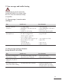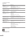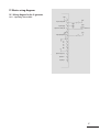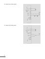
1
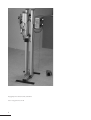
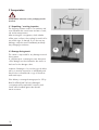
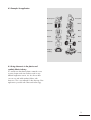
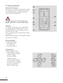
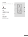
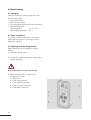
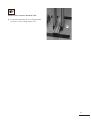
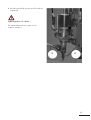
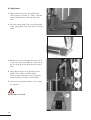
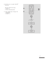
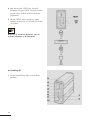
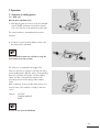
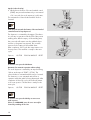
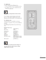
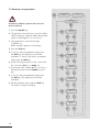
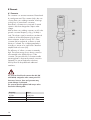
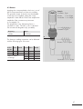
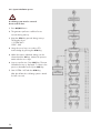
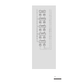
Operating Instructions
C U T T I N G S TAT I O N T Y P E 3 B A S E / T Y P E 5 TA B L E
English
W I T H A G E N E R AT O R S L 3 5
Copyright by Rinco Ultrasonics AG, Switzerland
Version 2.0, gb, Art.-No. 34134
2
Note
Before the machine is unpacked and started up, these
operating instructions must be read and their content
must be observed when operating the machine. The
machine may only be operated, serviced and repaired
by persons who are familiar with these operating
instructions and the current statutory regulations for
health and safety at work.
Specification
Maschine
3 21 1390 Typ 3
Article: 31836
Series: 1004
Year: 2002
Generator
SL 35 für 600 W
Article: 2772
Series: 1898
Year: 2002
Agency
3
Contents
1 Explanation of symbols and signs
7
2 Safety information
2.1 General
2.2 Intended purpose
2.3 Special points to note
2.4 Choosing staff
2.5 Installing the units
2.6 Operation
2.7 Noise emissions
2.8 Guarantee
8
8
8
8
8
8
8
9
9
3 Transportation
3.1 Unpacking/receiving inspection
3.2 Damage during transit
3.3 Positioning the plant
10
10
10
11
4 Product Information
4.1 Side view of cutting station
4.1.1 Cutting station
4.1.2 Ultrasonic generator
4.2 Examples for application
4.3 Using ultrasonics in the plastics
and synthetic fabrics industry
4.4 Advantages of welding and cutting
with ultrasonic
4.5 Cutting station functions and
characteristics
4.6 Technical data of cutting station
4.6.1 Insert
4.6.2 Booster
4.6.3 Structure
4.6.4 Compressed air
4.6.5 Weight
4.7 Technical data of ultrasonic generator
4.7.1 Dimensions SL35
4.7.2 Concept
4.7.3 Available generator modules
4.7.4 Connected loads
4.7.5 Dimensions
12
12
12
12
13
13
4
14
5 Control and display elements
5.1 Pneumatic group
5.2 Vibration system
5.3 Anvil
5.4 Fixing axis of anvil
5.5 Fixing clamp of anvil
5.6 Support arm of anvil
5.7 Controls and indicators
18
18
19
19
19
19
19
20
6 Commissioning
6.1 Setting up
6.2 Space requirement
6.3 Preparing and connecting the unit
6.4 Fitting the vibration system
6.5 Adjustments
6.6 Switching off
22
22
22
22
26
28
7 Operation
7.1 Sequence of welding process
7.1.1 Work cycle
7.1.2 Optimisation
7.1.3 Parameter setup
7.1.4 Description of setting
parameters
7.2 Parameter set-up procedure
7.3 Automatic connection
29
29
29
31
31
32
8 Elements
8.1 Converter
8.2 Booster
8.3 Horn
8.3.1 Horn materials
8.4 Cutting table for work piece (anvil)
36
36
37
38
39
40
9 Replacement
9.1 Replacing the booster
9.2 Parameter initialization
9.2.1 Description of selectable
functions
9.2.2 System initialization process
41
41
47
48
34
35
14
15
15
15
15
15
15
16
16
16
17
17
17
50
10 Cleaning and servicing
10.1 General servicing tasks
10.2 Vibration system and carriage
10.3 Pneumatic group
10.4 Generator
10.5 Oscillating system
10.6 Threaded coupling
52
52
52
53
53
54
54
11 Error messages and trouble shooting
11.1 Error messages/corrective actions:
switching on
11.2 Error messages and error elimination
during adjustments and welding
11.3 Generator error messages
during operation
55
55
12 Electric wiring diagrams
12.1 Wiring diagram for the SL generator
12.1.1 Operating element STO1
12.1.2 Manual starter
STO2 (standard)
12.1.3 Manual starter
STO2 (optional)
12.1.4 Automatic start-up
STO2 (pedal)
12.1.5 Interface STO3
12.2 Melting strips
12.3 Listing of fuses
12.4 Back part of generator SL35
12.5 Listing of the connection terminals
of the unit
57
57
57
58
55
56
58
59
60
61
62
62
62
13 Technical drawings and dimensions
13.1 Drawing of cutting station
13.2 Amplitude values of the
GM generator module series
13.3 Amplitude of SL generators
with 35 kHz
13.4 Length of screws of the different
components of the vibration system
for 35 kHz
63
63
64
14 Adresses of technical customer service
66
64
65
5
Important
Please quote the exact type designation and the
unit serial numbers in all enquiries concering your
Multipress and your Generator.
You will find this data on the rating plate (A) at the
back of each unit, as well as on the inside cover
flap of this operating manual.
The design and circuitry of these units are subject
to continuous further development and improvement,
and represent the latest state of the art.
RINCO ULTRASONICS AG
Romanshorn, Schweiz
Preface
Congratulations on the purchase of your cutting
station.
The purpose of this manual is to give the purchaser
and the user all the information they need in terms
of the handling, assembly, operation and care of
the cutting station.
To ensure that your system is always in an
operational state, you should take note of and
follow all the tips and instructions contained
within this manual.
6
A
1 Explanation of symbols and signs
Special attention should be paid to passages with
the following symbols:
Special information or operating instructions.
Warnings regarding risk of personal injury or
damage to parts of the equipment.
7
2 Safety information
2.5 Installing the units
2.1 General
The design of this unit conforms to the current state
of engineering and is safe to operate.
The individual modules and the complete unit are
subject to continual inspection by our quality
assurance department.
Always unplug the power cable before making any
connections to peripheral units.
Be sure to fit the power supply with a grounding
connector!
Observe any statutory safety regulations in force in
!
2.2 Intended purpose
your country!
The unit is intended exclusively for the ultrasonic
welding of suitable plastics. Any other use is
regarded as inconsistent with the intended purpose,
and is undertaken at the user's own risk.
The manufacturer is not liable for any resultant
damage. Intended for industrial use.
Failure to observe these regulations will exempt the
manufacturer from all liability for injury to persons or
damage to materials!
Before starting up the unit, always make sure it is in
a closed and safe condition.
2.6 Operation
2.3 Special points to note
• Before you start up the unit for the first time,
read this operation manual carefully.
• Being badly informed about how to operate and
look after the generator can result in damage.
• Always keep the operating manual handy at the
site of the unit.
• Do not perform any modifications, extensions
or conversions on the unit which might endanger
safety without the supplier's consent.
• Do not alter the programming (software) of
programmable control systems.
2.4 Choosing staff
Work on the electrical installations of the unit may
only be performed by an electrical specialist or
instructed staff under the management and supervision of an electrical specialist, according to
electrical engineering standards.
8
Never open the generator or converter housing while
the Multipress is in operation.
There is a high voltage inside the units – risk of injury!
Avoid any potentially unsafe working practices.
Correct operation and careful handling of the units
and their associated tools during operation will
• keep the system ready for service,
• prolong its useful life, and
• reduce stoppage times to a minimum.
2.7 Noise emissions
Caution!
Limits: Ultrasonic does not cause any damage
according to present scientific research as long as
the maximum noise level remains below 140 dB and
the average level, assuming an 8h/day, remains
below 110 dB.
Keep an eye on the sub harmonic i.e. audible
frequencies, which fluctuate depending on application and are annoying and harmful. Significant are
the energy equivalent, continuous sound levels
assuming a representative working period
(min. 8 h/day max. 2000 h/year) of 85-87 dB(A)
as limit.
If these limits are exceeded, the personnel must
have sound protection devices at their disposal or else
a machine specific sound protection is required.
(Specifications according to SUVA-Information
no. 86048 d 4.94)
2.8 Guarantee
With the supply of the unit, RINCO Ultrasonics AG
enters a guarantee in accordance with VSM
(Verein Schweizerischer Maschinen-Industrieller =
Association of Swiss Machine Manufactureres).
The following conditions apply in order for RINCO
ULTRASONICS AG to uphold the guarantee:
• The user must be familiar with the content of
these operating instructions.
• The instructions and notes contained in these
instructions must be observed.
• No reconstruction or changes to parts of the
machine or the generator are permitted.
In case of difficulties or questions, RINCO
ULTRASONICS AG offers telephone support
through qualified specialist personnel.
9
3 Transportation
Transportation instructions on the packaging must be
observed.
3.1 Unpacking / receiving inspection
The shipping container used for our machines and
units withstands the normal wear and tear of road,
rail and air transportation.
After receiving the consignment, check whether
all the parts conform to the packing list and look for
any visible signs of damage. If you discover any
damage, notify the carrier immediately and keep
the packaging as evidence.
B
3.2 Damage during transit
The carrier is responsible for any damage incurred
during transit.
A complete report containing an exact description
of the damage must be submitted to the carrier as
the basis for the damages claim.
Incidents of damage or loss involving goods delivered by us must be reported to us immediately and
they must be confirmed with a copy of the above
mentioned report.
If the delivery is arranged carriage paid or CIF by
RINCO ULTRASONICS AG, the damaged
consignment will be replaced if necessary and
claims will be levelled against the relevant
transit insurance.
10
B
3.3 Positioning the plant
The location of the unit is important. In order to
guarantee a long service life, the unit should be
installed in clean surroundings.
Make sure that the electronic equipment is mounted
in a vibration-free environment.
The factory settings are performed at 20° C. The
ambient temperature can range between 10° C
and 45° C during operation.
11
4 Product Information
4.1 Side view of cutting station
4.1.1 Cutting station
5
1
2
3
4
5
6
7
8
9
10
Main column
Support arm of anvil
Fixing plate
Support arm for insert
Pneumatics group
Vibration system
Anvil
Fixing axis of anvil
Fixing clamp of anvil
Insert carriage
4
10
1
6
2
7
8
9
3
4.1.2 Ultrasonic generator SL35
26
26.1
27
28
29
30
31
32
33
34
12
Handle of generator module
Handle of generator module when
specifying the model
LED display
Two-line LCD screen
Input keyboard
Key TEST US
Displays
US ON (green)
VALVE (green)
ERROR (red)
“On / Off” key
LED display for the unit during operation
Fixing screws
4.2 Examples for application
Electric power
Power/fuel
Generator
Driver
Converter
Motor
Booster
Gears
Sonotrode
Drive
Ready for
welding
Ready
4.3 Using ultrasoncis in the plastics and
synthetic fabrics industry
It is well known that thermoplastic materials come
in many shapes and sizes and are used in very
different application areas. It is also known that
one can cut and weld synthetic fabrics with
ultrasonic. This is an example for the diversity of the
applications possible with ultrasound technology.
13
4.4 Advantages of welding and cutting with
ultrasonic
Ultrasonic welding is used as part of an assembly
process for the manufacture of large series of
quality products. Its major advantage is the cost
effectiveness. Cutting with ultrasonic has the great
advantage that it will result in a clean cut and
that the edge of the fabric is fused so that any
tearing is prevented.
Ultrasonic is an environment-friendly technology
without additional input materials. For this reason,
ultrasonic welding is recommended in sterile areas
since there is no danger of contamination from
additives.
The typical work cycle of an ultrasonic welding
process is no longer than a fraction of a second.
Once the welding process has been completed the
melted seam will become hard again.
At this point it is possible to process and transport
the work piece, i.e. it is ready for the next process
step. No additional work sequence is required.
Ultrasonic welding is carried out with the material
of the item itself, i.e. no external additives have
to be added such as bonding agents, solvents, etc.
This means that the assembly processes can be
easily automated and productivity increased.
Not much energy is required for the welding
process. The efficiency of the welding system is 95%.
4.5 Cutting station functions and characteristics
The cutting station and generator developed by us
combine to a system with mechanical precision as
well as durability and versatility. At the same time,
we have endeavoured to make the operation and
use of the unit as easy as possible.
The vertical level of the machine can be adjusted
with the help of the fixing screws of the brackets.
An adjustment mechanism can be used to align the
anvil in parallel to the front face of the sonotrode.
14
4.6 Technical data of cutting station
Dimensions in mm
4.6.1 Insert
• Maximum travel of insert: 40 mm
• Adjustable depth stop
• Precision guides of linear ball bearings
in insert
• Double action cylinder
• Switch for top position of cylinder
(optional)
• Piezoelectrical converter
• Connection thread / fixing thread
for sonotrode M 8
4.6.2 Booster
Reduce
Booster
1:0.5
1:0.6
Colour Material
Booster Colour
blue aluminium 1:1
violet aluminium 1:1.5
1:2
Further characteristics in
1:2.5
accordance with order
1:3
green
yellow
white
black
brown
Material
aluminium
aluminium
titanium
titanium
titanium
4.6.3 Structure
• Construction with ‘Heron’ brand aluminium
profile
• Fixing axis of anvil with fixing clamp
• Pedal
4.6.4 Compressed air
• Dry compressed air, maximum 7 bar (105 PSI)
4.6.5 Weight
• Weight: 90 kg
15
4.7 Technical data of ultrasonic generator
4.7.1 Dimensions SL35
Dimensions in mm
Weight 7 kg
4.7.2 Concept
• Flexible module system with various insert
modules.
• Clear and simple parameter input with 2- line
LCD display.
• Optimal efficiency and minimal energy
dissipation by using microprocessor regulated
frequency control.
• Real time microprocessor regulator to maintain
constant amplitude under varying loads.
• Maintains constant amplitudes during power
fluctuations.
• Recognizes system errors and outputs detailed
error messages on the LCD display.
• Electronically adjustable amplitude output.
• Variable start-up characteristics (softstart) for
optimal adaptation to large size welding
equipment (except SLH20).
• Interface to connect to SPS master control.
16
4.7.3 Available generator modules
Type
max. power
GM 35-400
GM 35-600
GM 35-900
400 W
600 W
900 W
4.7.4 Connected loads
• 230 V 50-60 Hz / maximum current
consumption 6.3 A
• consumption 110 V (up to 600 W)
4.7.5 Dimensions
• see Fig. page 16
17
5 Control and display elements
5.1 Pneumatic group
1
1 Pressure controller
The pressure controller is used to reduce the
welding pressure. In order to select a nominal
value, pull out the control knob and turn to the
required position. Push the knob back in order
to fix it in that position.
Maximum connection pressure: 7 bar
2
3
4
2 Pressure indicator
The pressure gauge indicates the maximum
pressure selected for welding.
3 Solenoid valve of cylinder
5
The cylinder is activated via an electric signal in
order to move towards the cutting position.
7
9
6
4 Solenoid valve for cooling
An electric signal activates a fan in the areas with
a heat load (converter and sonotrode).
5 Fan switch for converter
8
6 Fan switch for sonotrode
7 Speed switch for the upwards movement of the insert
8 Speed switch for the downwards movement of the
insert
9 Control screw for the downward movement stop
Release the counter nut and adjust the screw with
the insert in the lower position until it touches the
point of the anvil; then retighten the counter nut.
10 Connection for compressed air
10
18
5.2 Vibration system
4
1 Converter
2 Booster
1
3 Sonotrode
10
2
4 HF connection
10 Carriage insert
3
5.3 Anvil
7
9
Anvil
8
5.4 Fixing axis of anvil
7
8
Fixing axis of anvil
2
5.5 Fixing clamp of anvil
9
Fixing clamp of anvil
5.6 Support arm of anvil
2
Support arm of anvil
19
5.7 Controls and indicators
26 Generator module grips
If necessary, you can pull out the generator module
by holding these grips. The fastening screws (34)
for opening the generator module are located
above and below the grip bars.
The generator module is never to be pulled out or
plugged in while mains is connected. (high voltage)
27 LED bar
This display indicates the power supplied during
the welding operation. When the horn is idle
(vibrating freely in the air), the display should not
rise above the 25% mark.
An error message will be issued if the 100% mark
is exceeded.
After the welding operation a flashing LED indicates
the peak power supplied.
28 2-line LCD display
The LCD display shows:
• Welding parameters
• Error messages
• Operating conditions
29 Input keypad
Using this keypad you can
• activate generator functions.
• change welding parameters.
a) zeroes, display
b) increase number
c) decrease number
d) select number to the left
e) select number to the right
f) return by one program line
g) to next program line
h) enter / exit program
20
30 Key "US-TEST"
Key to activate ultrasonics test. The display shows
the current horn frequency. If the key is activated
formore than 5 seconds, the error message comes
on.
Do not touch horn!
31 LED
• "US-ON" Ultrasonics active
• "VALVE" Solenoid valve active
• "ERROR" Error output active
32 Key "ON/OFF"
Mains switch
33 LED
"POWER" indicator
34 Fastening screws
Must be locked in operation!
21
6 Commissioning
6.1 Setting up
Select the location for setting up the unit under
the following criteria:
• Clean environment
• Firm and level surface
• The cutting table area must free from vibrations
• Ambient temperature:
During operation:
10° C – 45° C
While adjusting settings: 20° C
6.2 Space requirement
The location where the machine is set-up must
afford sufficient space for servicing as well as
adjustment activities.
6.3 Preparing and connecting the unit
When setting up the unit, please proceed as
follows:
1. Attach the cutting station.
2. Connect the cables between the cutting station
and the generator.
Only earthed mains connections may be used.
3. Plug the cutting station connectors into
the generator sockets.
1 STO1 Insert
2 STO2 Start (optional)
3 STO3 Interface (optional)
4 STO4 Converter connection
5 STO5 Mains connection
22
Compressed air connection: maximum 7 bar
4. Connect the pneumatic hose to the pneumatic
connection on the cutting station (10).
10
23
6.4 Fitting the vibration system
It is imperative to switch off the generator prior
to fitting the vibration system.
1. Release the screws (1) with the allen key
(6 mm).
2. Insert the converter and the booster (already
1
assembled) through the lower part up to the stop
and then tighten the screws (1).
3. Connect the HF plug to the HF terminal (2) of
the converter and connect the cooling pipe (3).
2
3
1
24
4. Put the sonotrode (4) in place and fix it with the
spanner (5).
Tightening moment: 15 – 25 Nm
The ultrasound transmission system is now
ready for operation.
5
4
25
6.5 Adjustments
1. Release the pressure from the cylinder and
set the pressure controller to “0 bar”; lower the
insert manually down to the stop above the
anvil.
2. Place the cutting edge of the sonotrode exactly
to the cutting edge of the anvil at the end of the
radius.
3. Release the nut (2) and tighten the screw (1) up
to the stop of the cutting table (3). Then remove
the sonotrode by a few decimal units from the
anvil.
1
4. Adjust the pressure to 2 kg and step on the
pedal (16) in order to activate cutting.
Then proceed to adjust the screw (1) until the
machine performs a clean cut of the fabric.
2
5. Lock the nut (2) and the machine is now ready
3
for operation.
Do not touch the sonotrode.
26
16
6. Switch the unit on using the “ON/OFF”
button (32).
After the US-TEST, the message
>> READY <<
is shown on the display (28).
7. Use the “SETUP” key to change to the
* PARAMETER *
>> ADJUST <<.
US-TEST
>> READY <<
* PARAMETER *
>> ADJUST <<
27
8. After pressing the “SETUP” key, check all
parameters using the “NEXT” key and enter the
nominal values, if these are known from the
specification.
9. Use the “SETUP” key to change to normal
operation and the unit is now ready for the first
cut of fabric.
Please refer to “Parameter adjustment”, page 34,
for further information on the adjustments.
* PARAMETER *
>> ADJUST <<
6.6 Switching off
1. Use the ON/OFF key (32) to switch off the
generator.
28
7 Operation
7.1 Sequence of welding process
7.1.1 Work cycle
Manual starter (standard mode)
1. After pressing the two buttons of the two-handed
control (START) simultaneously with an interval
of 0.3 seconds, the work sequence (cycle) starts.
The solenoid valve is activated and the insert is
lowered.
2. Continue to press the two-handed controls until
the ultrasound is activated.
If the two-handed controls are released too early, the
insert retracts to its home position.
The ultrasonic is initiated by the trigger. The
ultrasonic will stay in operation until the end of the
pre-set welding time. After the expiry of the welding
time, the sonotrode will remain over the welded
object until the cooling time has expired. This
provides pressure for the setting of the welded
seam.
After completion of the cycle the insert returns to its
home position. The machine is ready for the next
cycle.
Options:
US-STOP
FOLLOW IMPULSE
RESET
To clear an error press the CLR button.
29
Impulse (reduced safety)
1. When the two buttons of the two-handed control
(START) are pressed simultaneously in an interval
of 0.3 seconds, the work sequence (cycle) starts.
This activates the solenoid valve and the insert is
lowered.
From this point onwards the buttons of the two-handed
control must not be kept depressed.
The ultrasonic is initiated by the trigger. The ultrasonic will stay in operation until the end of the pre-set
welding time. After the expiry of the welding time,
the sonotrode will remain over the welded object
until the cooling time has expired. This provides
pressure for the setting of the welded seam.
After completion of the cycle the insert returns to its
home position. The machine is ready for the next
cycle.
Options:
US-STOP
FOLLOW IMPULSE
RESET
To clear an error press the CLR button.
Automatic (for automatic operation without safety)
The work sequence is started by an impulse lasting
100 ms at the input of START 1 (STO2). The
solenoid valve is activated and the insert is lowered.
The ultrasonic is now activated and will be in
operation while the pedal is being depressed. After
completion of the work cycle, the insert will retract
to its home position. The machine is ready for the
next cycle.
Options:
US-STOP
FOLLOW IMPULSE
RESET
To clear an error press the CLR key or start a new
work sequence.
If there is a HARDWARE error, the error can only be
cleared by switching off the unit.
30
7.1.2 Optimisation
In order to optimise the welding process,
• only one parameter must be changed at a time,
• the welding result must be checked after each
change of a parameter.
Never change several parameters at the same time.
If one changes several parameters at the same
time, it is not possible to establish which of the
parameters has had an effect on the welding result.
7.1.3 Parameter setup
Setting parameters are available according to
initialization of generator. They can be modified as
required.
For activating the parameter setup see following
page.
Parameters to be set up
Setting
Part counter
Welding time
Hold time
Trigger
After-pulse
Amplitude
Performance limits
After impulse
[ADJUSTING :]
[PART :]
[WELDTIME :]
[HOLDTIME :]
[TRIGGER :]
[AFTERPULSE :]
[AMPLITUDE :]
[PERFORMANCE MIN:]
[PERFORMANCE MAX:]
[AFTERPULS :]
It is advisable to record the respective changes in a
setup log in order to be able to return to existing
settings whenever necessary.
31
7.1.4 Description of setting parameters
Setting [ADJUSTING :]
• Press both start buttons within 0.3 seconds to
lower the actuator. Keep the start buttons
actuated until safety switch is reached. Press
start buttons again to move actuator back
to the home position.
Part counter [PART :]
• The part counter steps up by one after each
sound welding. Press CLR key to reset part
counter.
• Maximum display: 9999999
Welding time [WELDTIME :]
• Duration of welding.
• Setting range: 0.00 – 9.99 s
• Standard setting: 1.00 s
This parameter is operative only if the function
[WELDTIME: TIMER] is operative in the * SYSTEM--INIT *.
Hold time [HOLDTIME :]
• Upon exipation of the welding time the horn
keeps exerting
pressure on the welding object for the HOLD TIME.
• Setting range: 0.00..9.99 s
• Standard setting: 1.00 s
Trigger [TRIGGER :]
• Upon reaching the TRIGGER, the generator is
started. The FU-trigger point is determined by a
force sensor.
• Setting range: 0.00 – 9.9 FU
This parameter is operative only if the [TRIGGER:
FU] function is operative in the * SYSTEM--INIT *.
32
Trigger [TRIGGER :]
• Upon reaching the TRIGGER, the welding
is released.
• Setting range: 0.00 – 3.99 s
This parameter is operative only if the [TRIGGER:
TIMER] function is operative in the * SYSTEM--INIT *.
After impulse [AFTER.PULSE]
• Duration of after impulse after end switch
shut off:
• Setting range: 0.00 – 1.99 s
• Standard setting: 0.00 s
Amplitude [AMPLITUDE :]
• The amplitude may be reduced from 100% to
60% by step of 5%. A change of the booster
may thus be avoided.
• Output amplitude: see page 64
• Setting range: 1 – 9 (9 = 100%)
• Standard setting: 5
Maximum output power drops with a reduction of the
amplitude.
33
7.2 Parameter set-up procedure
RINCO ULTRASONIC
SWITZERLAND
>> US-TEST <<
++++++++++++
>> READY <<
PART : 1234567
An ultrasonic vibration system must be connected.
Do not touch horn!
1. Press the ON/OFF key.
* PARAMETER *
>> ADJUSTING <<
2. The generator starts with a two seconds' self-test
while warming up. After the self-test the vibration
system is tested again for a 1/2 second.
3. Upon termination of tests the message
>> READY <<
PART: 1234567 appears on the display.
* PARAMETER *
PART : 1234567
4. Press the SETUP key.
5. To move to the next parameter setting: press
the NEXT key. The display shows the next
parameter. To return to the previous parameter
setting press the PREV key.
* PARAMETER *
WELDTIME: 9.99s
6. Move to the required point on the counter with
–>
the cursor keys LEFT ( <–) or RIGHT (–>).
7. Increase the value with the UP ( ) cursor key or
decrease the value with the DOWN ( ) cursor
key.
* PARAMETER *
HOLDTIME : 9.99s
–>
8. To move to the next parameter setting: press
the NEXT key. The display shows the next
parameter.
* PARAMETER *
TRIGGER : 9.99s
9. Exit the parameter set-up with the SETUP key.
The system is ready for welding.
* PARAMETER *
AFTERIMPLUSE: 9.99s
* PARAMETER *
AMPLITUDE : 9
34
7.3 Automatic connection
The operating switch (ON / OFF) can be activated
or deactivated. To open the generator module (32)
it is necessary to,
1. release the four screws (34),
2. pull the handles (26) outwards towards the
guides. The steady is in the rear top position (35).
Standard position
The steady is in the top position and the ON / OFF
switch (32) is activated.
Automatic option
The steady is in the bottom position and the
ON / OFF switch (32) is deactivated. Start-up will
be initiated automatically when the unit is
connected to mains power.
Steady is in the
top position
Steady is in the
bottom position
35
8 Elements
8.1 Converter
The converter is a sensitive instrument. Please handle it with great care! The converter (24) is the core
of every ultra sonic welding instrument. It belongs
to the group of piezoelectric converters.
Piezoelectric converters are composed of several
ceramics disks that change their shapes under
voltage.
With an ultra sonic welding converter, an AC voltage with a nominal frequency of (e.g. 20 kHz) is
used. This electric signal is turned into mechanical
oscillations of the same frequency by the piezoelectric elements. At the front end, "K1" of the
converter (24) a mechanical oscillation in axial
direction is created. The oscillating amplitude is
normally too minute to be useful and is therefore
amplified with a booster (25).
The efficiency of a Piezo converter is extremely
high. The minute energy losses during conversion
are traceable in the heat build up in of the
converter. The special build of converters enable
remaining heat to dissipate by natural convection.
Optimally, for special applications the heat
build up must be dissipated with additional
ventilators.
The converter should not be warmer than 50° (40°
with 70 kHz) centigrades at the contact point "K1".
Converters, boosters, horns and generators may
sustain damage if overheated.
The converter must be tightened with torque values
listed in the following table.
Frequency
Torque
20 kHz
35 kHz
70 kHz
30-40 Nm
15-25 Nm
1.8-2.2 Nm
36
8.2 Booster
Applying the correct amplitude to the horn is one of
the most important factors in ultra sonic welding.
The geometric shape of the horn must be adapted
to the object to be welded. Setting the correct
amplitude is often difficult. The booster amplifies the
amplitude of the converter at a preset ratio.
In our example 1:2.
The amplification resp. dampening factor is
specified as a ratio. The ratio is color coded and
has a numerical designation (A). (see table)
Example
Converter: 5 µm
Booster:
1: 2 –>10 µm
Sonotrode: 1: 3 –> 30 µm
Converter = 5 µm
Frequency
Torque
35 kHz
15-25 Nm
A
The ultrasonic welding instruments can be delivered
with the following types of boosters:
Reduce
Booster
1:0.5
1:0.6
Colour Material
Booster Colour
blau Aluminium 1:1
violett Aluminium 1:1.5
1:2
andere Verhältnisse
1:2.5
auf Anfrage
1:3
grün
gelb
weiss
schwarz
braun
Booster = 1: 2 –> 10 µm
Material
Aluminium
Aluminium
Titan
Titan
Titan
Sonotrode = 1: 3 –> 30 µm
37
8.3 Horn
Any kind of change to the metallic body of the
horn influences the oscillating characteristics and therefore none should be made without consulting the
manufacturer!
The horn transmits the ultra sonic energy to the
object to be welded in form of intense oscillations
created by the converter.
Work pieces come in various shapes and the horns
must be adapted to the shapes as required. The
horn is an acoustic body tuned to the frequency of
resonance.
That sets limits to the shapes it may take. The
geometric shape of the horn should be kept as
simple as possible.
In addition to the geometric shapes, other important
factors are to be considered:
1. The horn has to be tuned to the frequencies of
resonance according to the table.
frequency of resonance Tolerace
35 kHz ±50 Hz +150 / -250 Hz
2. To let the horn oscillate correctly, it should be
shaped to move in the most axial direction to
the surface to be welded, with the aim of
transmitting the most pulses from the frontal area
of the horn onto the object to be welded.
3. The amplitude of the horn is determined by the
shape of the horn.
Most important in manufacturing the horn is:
• Extensive knowledge about the load factors of
the various materials.
38
8.3.1 Horn materials
Horns must be made of special high load material.
Only high load aluminum, titan and steel alloy are
used.
The choice of material depends mostly on the
intended application.
Other factors also influence the choice of material:
1. Rigidity of the material used for the horn in
connection with the targeted oscillation
amplitude.
2. Surface properties of the work piece and the
related surface treatment properties.
3. The sound transmission properties.
4. The heat transmission properties of the horn
material.
It must be taken into consideration that the horn is
subjected too extreme mechanical loads.
It is therefore of utmost importance to shape the
horn in such a way that the plastics part to be
welded is welded under optimal conditions.
With abrasive plastics, a coating of the horn surface will increases its life span.
RINCO has years of experience in manufacturing
horns. Manufacturing horns without the theoretical
and practical experience leads to unsatisfactory
and bad welding results and to poor product
quality.
In some cases the oscillating system and the generator
may be damaged.
The horn must be fastened with a tightening torque to
15 – 25 Nm.
39
8.4 Cutting table for work piece (anvil)
The cutting table for the work piece or anvil has
several functions:
• to maintain the distance between the cutting
edge of the work piece and the cutter,
• counter plate for the cutter so that this will
carry out a clean cut,
• absorbing any vibrations and avoiding
excessive wear.
In many cases, the quality of the cut depends on
the shape of the cutting table and the work piece.
It is recommended that the manufacturer of the
sonotrode also produces the cutting table since he
will be more familiar with the requirements of
the application.
40
9 Replacement
9.1 Replacing the booster
Before releasing the converter clamp (2) it is imperative
that the main power switch is turned “OFF”.
1
2
1. Release the bolts and the sonotrode (3) using
the spanner.
3
2. Release the screw fixing (1) with the allen key
(5mm).
3. Pull out the cooling pipe (4).
4. Remove the plug from the HF terminal (5) of
the converter.
5. Move the whole vibration system downwards.
4
5
41
6. Move the vibration system through the lower
part of the clamp (2) with the booster upwards.
7. Use the allen key 5 to tighten the screws (1) of
the clamp (2).
2
1
8. Release the converter (6) with the special span-
ner (A) and detach the booster (7) by releasing
the screws.
9. If the thread is slightly seized up, loosen the con-
verter (6) with a light tap with your hand; use
the spanner (A) as shown in figure 5.
7
6
42
A
10. Again release the clamp (2).
11. Pull the booster (7) out.
12. Attach a new booster to the bracket (2) with
the thread facing downwards so that it can be
screwed to the converter (6).
2
7
6
43
13. Lock the clamp (2) by tightening the screws (1).
1
14. Make the screw connection between the con-
verter (6) and the booster (7) and use the special spanner (A) to pull tight.
7
2
6
A
15. Again release the clamp (2).
16. Pull the converter (6) together with the booster
(7) (which has been screwed to the converter)
out and turn it.
2
7
6
44
17. Again place the complete vibration
system with the converter (6) uppermost.
5
4
18. Connect the plug to the HF terminal (5) and
connect the cooling pipe (4).
7
1
19. Turn the screws (1) to tighten the clamp (2) of
the converter.
20. Again make the screw connection between
the sonotrode (3) and the booster (7).
21. Tighten the sonotrode (3) with the spanner (8).
1
2
8
3
45
22. Align the sonotrode vertically at the anvil by
releasing the clamp (2) with the screws (1)
and then tightening the clamp (2) again once
it has been positioned.
10
1
2
23. Release the fixing clamp of the anvil (9) with
the screws (10). Slide the bar of the anvil
along until the cutting edge of the sonotrode is
placed exactly at the end of the radius; then
retighten the clamp (9).
24. For further information regarding the
adjustment of the cutting edge see section
6.5 Adjustments.
46
9
9.2 Parameter initialization
To prepare the Multipress and the Generator for
their various tasks, the individual press functions
are initialized according to the mode of operation
via the generator control system.
Press the PREV key and keep this depressed during
firing up in order to activate the standard start-up.
Press the CLR key in order to confirm the standard
start-up.
When pressing the SETUP key the standard start-up
will be interrupted.
In the * SYSTEM--INIT * menu you can select the
following functions:
• START
[MANUAL/IMPULSE/
AUTOMATIC]
[FU/TIMER/EXTERNAL/RS/OFF]
• TRIGGER
• WELDING
[TIMER/EXTERNAL]
• VALVE
[ON/OFF]
• END SWITCH
[ON/OFF]
• SOFTSTART
[1-9]
• AFTERPULSE
[ON/OFF]
• LANGUAGE
[GERMAN/
ENGLISH/
FRENCH/
ITALIAN/
SPANISH/
DUTCH/
DANISH/
NORWEGIAN/
SWEDISH/
FINNISH]
• AMPLITUDE*
INTERNAL/EXTERNAL]
• SDF*
[ON/OFF]
• TRIGGER
[BEFORE/AFTER]
• PERFORMANCE
• LIMIT*
[ON/OFF]
47
9.2.1 Description of selectable functions
START (MANUAL)
• The generator must be started up MANUALLY.
TRIGGER (FU/TIME)
• The TRIGGER can be confirmed with FU or
TIME.
• Standard setting: FU
WELDING TIME (TIME)
• The generator must be started up in TIME.
VALVE (YES/NO)
• The generator must be started up in the YES
position.
F-C US (YES/NO)
• This function is activated when a unit was started with YES.
• Standard setting for initiation: NO
• A signal at input 2 or 3 of the connection
interface interrupts the ultrasound. After the
interruption a second welding can be carried
out by pressing the two-handed controls. If no
signal is emitted, the ultrasound will be
interrupted once the welding time has elapsed.
An error message is activated.
LANGUAGE (SPANISH/ENGLISH)
• Standard setting: ENGLISH
AMPLITUDE (YES/NO)
• If NO has been selected for starting up, the
amplitude can be selected in the parameter
submenu.
• Standard setting: NO
• When YES has been selected for start-up, the
amplitude can be selected outside with the
potentiometer or with a voltage of 0 – 5 V DC.
Option A
• With the 10 Ω potentiometer
Option B
• With a voltage of 0 – 5 V.
• If the internal voltage is not used, the earth
connection GND 5 V is connected outside to
GND.
• 0 V = 60%, 5 V = 100%
48
SOFTSTART (1-9)
• The duration from starting up to reaching the full
amplitude can be adjusted in 9 steps.
1 Slow start of vibration for sonotrodes with a
large volume
9 Fast start of vibration for small sonotrodes
• Standard setting: 7 (See illustration)
SDF (YES/NO)
• This function is not activated unless YES is selected for start-up.
• Standard setting: NO
• Starting aid for starting up sonotrodes with
large volume.
TRIGGER (BEFORE/AFTER)
• In the case of AFTER, the trigger is activated
after the safety contact.
• In the case of BEFORE, the trigger is activated
during the lowering movement. It is required
when the welding distance is more than 6 mm.
• Standard setting: AFTER
RESET
• A signal of 24 V DC at the RESET input will
interrupt the work cycle.
The machine will retract to its home position and
indicate an error.
49
9.2.2 System initialization process
RINCO ULTRASONIC
SWITZERLAND V2E0
A oscillating system must be connected.
Do not touch the horn.
1. Press ON/OFF button.
* SYSTEM--INIT *
CODE : 000
2. The generator performs a self-test for two
seconds during start up.
* SYSTEM--INIT *
CODE : 472
3. Keep the SETUP key pressed during start up.
The display shows:
* SYSTEM--INIT *
CODE : 000
4. Using the cursor keys, set code to 472.
* SYSTEM--INIT *
START : MANUAL
Acknowledge by pressing the SETUP key.
5. Within the menus individual settings can be
selected with the CLR key. Numerical input are
made with the cursor keys.
* SYSTEM--INIT *
TRIGGER : FU
6. Jump to next function. Press NEXT key. The next
selectable function is displayed. To return to the
previous selectable function press PREV key.
7. Quit SYSTEM - INIT with the SETUP key.
After the self-test the oscillating system is tested
for half a second.
>> US-TEST <<
++++++++++++
>> READY <<
PART : 1234567
* SYSTEM--INIT *
WELDTIME : EXT.
* SYSTEM--INIT *
VALVE : ON
* SYSTEM--INIT *
US-STOP : OFF
50
* SYSTEM--INIT *
SOFTSTART : 5
* SYSTEM--INIT *
LANGUAGE:ENGLISH
* SYSTEM-INIT *
AMPLITUDE: OFF
* SYSTEM--INIT *
SDF : OFF
* SYSTEM-INIT *
TRIGGER : AFTER
51
10 Cleaning and Servicing
10.1 General servicing tasks
5
4
10
All cleaning and servicing must be carried out by qualified personnel.
1
6
2
Prior to starting servicing, it is imperative to check that
all services, such as power and compressed air, have
been switched off.
7
8
9
Important: never clean the keyboard and the front of
the generator with corrosive agents.
3
Neither the cutting station nor the generator require
special servicing.
However, regular cleaning of the following parts
enhances the service life of the unit:
• pneumatics group (5),
• vibration system (6),
• anvil (7),
• carriage (10)
10.2 Vibration system and carriage
Daily cleaning:
• Converter (6)
• Booster (7)
• Sonotrode (3)
6
7
3
52
10.3 Pneumatics group
No servicing required.
10.4 Generator
Ensure that the display screen of the generator is
always clean.
53
10.5 Oscillating system
Work may only be carried out on the vibration system
and converter housing when the mains voltage is
switched off! High voltage!
Avoid contact with the RF connection of the
converter.
Never connect any measuring instruments to the
RF socket of the converter!
The converter is electrically charged even after
switching off the generator.
10.6 Threaded coupling
Converter (24), booster (25) and horn (9) are
screwed together.
Torque: 35 kHz 15-25 Nm
Black spots on the surfaces of the booster (25) or
the horn (9) are easily removed.
1. Place a polishing cloth on an even surface
2. Draw blackened spot over the cloth.
54
11 Error messages and trouble shooting
Troubleshooting may only be carried out by
specially trained staff. In case of doubt, contact
the service centre or the manufacturer directly
(see appendix).
11.1 Error messages / corrective action:
switching on
Error
Possible cause
Error elimination
Generator cannot be
switched on
–
–
–
–
–
–
–
–
–
–
–
–
After being switched on,
the display shows:
no voltage supply
EMERGENCY STOP button pressed
fuse faulty
module not in its housing
vibration system not in use
RF cable not plugged in the
vibration system or generator
– error in vibration system:
a) not screwed together firmly enough
b) horn defective our outside
the frequency
c) booster defective
d) Converter defective
insert mains plug
release EMERGENCY STOP button
test fuses F1– F5
insert module and bolt together
use vibration system
plug in RF cable
– screw together more firmly
– replace horn
– replace booster
– replace converter
11.2 Error messages and error elimination
during adjustments and welding
Error
Possible cause
Error elimination
The insert is lowering but the
ultrasonic does not work
In spite of increasing the
welding time, the parts do
not fuse
The machine retracts to its
home position without welding
– The setting of the trigger is very high
– The pressure sensor is defective
– The stop setting is very low
– Select a lower setting
– Replace the pressure sensor
– Adjust the stop to a higher setting
– The safety switch was not reached
– Keep the two-handed controls
depressed until the unit reaches
the safety switch or starts welding
55
11.3 Generator error messages
during operation
Error
Possible causes
«OVERLOAD1»
The generator was charged over
100% of nominal power
–
–
–
–
–
–
«OVERLOAD2»
The generator had to utilise to the
full the final stage reserve capacity
«TRIGGER»
Trigger point not reached after
10 seconds
«FREQUENCY»
Vibration system out of frequency
range of generator
«TIME OVERFLOW»
Operation time has exceeded
«RESET»
The plant returns to stop as a
result of an external signal
«ABORT»
Welding could not be carried-out
according to program
«HARDWARE»
Cancel error by pressing the CLR key.
The «Hardware» error can only be
canceled by switching the unit off.
56
Trigger set too high
maximum welding pressure too high
Generator output too low for intended application
Vibration system defective
Amplitude too low at contact cut off during cutting operations
Mains voltage below nominal tolerance
–
–
–
–
–
–
–
–
–
–
–
Trigger set too high
wrong Parameter initialization
Trigger system defective
faulty horn or horn incorrectly tuned
faulty booster
faulty converter
faulty RF cable or RF cable not connected
faulty generator
frequency change due to coupling with the fixture
the US-TEST key was pressed longer than 5 seconds
the control time has been exceeded during an application using
contact cut off.
– 24V signal was aborted at entrance 7 of the Interfaces
– start button releases before safety switch was reached or before
hold time run out
–
–
–
–
–
–
–
–
defective valve in the feeder
defective pressure monitoring switch in the feeder
defective safety witch
defective upper end position switch
upper end position switch not adjusted
Stroke less than 6 mm
Malfunction in the generator
defective two-hand trigger
12 Electric wiring diagrams
12.1 Wiring diagram for the SL generator
12.1.1 Operating element STO1
Input for safety switch
Input for trigger
Output from solenoid valve
Input top limit position
Input emergency stop
Input N/O 1
Input N/C 2
57
12.1.2 Manual starter STO2 (standard)
Input emergency stop
Input N/O 1
Input N/O 2
12.1.3 Manual starter STO2 (optional)
Input emergency stop
Input N/O 1
Input N/O 2
58
12.1.4 Automatic start-up STO2 (pedal)
Input emergency stop
Input N/O 1
Input N/O 2
59
12.1.5 Interface STO3
Input US-stop 1
Input US-stop 2
Output reserve
NC
Input reset
Input amplitude
Error
- max. 24V / 0.5A
- open in case of an error
Insert in position
- max. 24V / 0.5A
- open if not positioned
60
12.2 Melting strips
The melting strips are situated on the following components:
On the base of the mains terminal
Bus print
Module of generator
All fuses are of equal size: 5 x 20 mm
61
12.3 Listing of fuses
Generator
GM35-400
GM35-600
GM35-900
Base of mains terminal
Bus print
Module of generator
F1
F2
F3
F4
F5
4 A/T
4 A/T
6,3 A/T
4 A/T
4 A/T
6,3 A/T
400 mA/T
400 mA/T
400 mA/T
4 A/T
4 A/T
6,3 A/T
100 mA/T
100 mA/T
100 mA/T
12.4 Back part of generator SL 35
1
2
3
4
5
STO1
STO2
STO3
STO4
STO5
12.5 Listing of the connection terminals
of the unit
List of generator base plates
STO1
STO2
STO3
STO4
STO5
Base
Base
Base
Base
Base
plate
plate
plate
plate
plate
RINCO order number
14-pole AMP
7-pole AMP
SUB-D 15-pole
Lemo 1
250V / 8A
List of terminal connections
ST1
ST2
ST3
ST4
ST5
62
Plug
Plug
Plug
Plug
Mains cable
5445
5442
5469
7255
120-1517
RINCO order number
14-pole AMP
7-pole AMP
SUB-D 15-pole
Lemo 1
250V
5443
5440
5446
2647
depending on country
13 Technical drawings and dimensions
13.1 Drawing of cutting station
63
13.2 Amplitude values of the GM generator
module series
The different generator outputs generate different
amplitudes. The value of the amplitude described
in the diagram below refers to the respective
configuration of the generator/booster/sonotrode.
The effective amplitude of the welding is directly
listed.
9
24
25
A
K1
K2
Sonotrode
Converter
Booster
Amplitude
Connecting surface
Connecting surface
13.3 Amplitude of SL generators with 35 kHz
Sonotrode
64
Booster
13.4 Length of screws of the different
components of the vibration system for 35 kHz
2.4 Converter
The screw is an integral part of the converter, it cannot
be removed.
25 Booster
The connecting surfaces are placed exactly parallel
between the front and connection face.
9.1
9
Sonotrode
9.1 Sonotrode screw
The sonotrode screw is manufactured from highly
resistant steel or titanium.
65
14 Addresses of technical customer
service
The RINCO ULTRASONICS customer service is
available for you in case of faults or welding
problems.
A
In order to be able to give you correct advice, our
customer service requires the following data:
1. Model and serial number of your unit
2. An exact description of the fault or cutting
problem
Our address:
RINCO ULTRASONICS AG
Industriestrasse 4
CH-8590 Romanshorn
Switzerland
Switzerland
Phone 071 466 41 00
Fax
071 466 41 01
International
Phone ++41 71 466 41 00
Fax
++41 71 466 41 01
www.rincoultrasonics.com
66
R
A CREST GROUP COMPANY
RINCO ULTRASONICS AG
Industriestrasse 4
CH -8590 Romanshorn 1
Switzerland
Phone +41 71 466 41 00
Fax
+41 71 466 41 01
[email protected]
www.rincoultrasonics.com