1
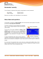
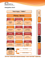
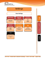
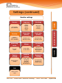
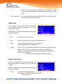
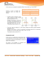
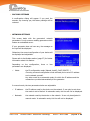
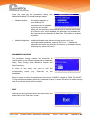
User Manual Display and Firmware Generator model “W“ with rotary encoder 2015-01-29 soniKKs GmbH - Ultrasonics Technology Doc.nr.: 3010.2399a page 1 of 43 Table of contents Table of contents ................................................................................................................. 1 Parameters’ security ............................................................................................................. 4 Menu items and operation ..................................................................................................... 4 Status LEDs ......................................................................................................................... 5 Navigation chart ................................................................................................................... 6 Structure of the menu and functions ...................................................................................... 9 1. Overview ..................................................................................................................... 9 2. Time & Energy ............................................................................................................. 9 3. Power .......................................................................................................................... 9 4. Frequency .................................................................................................................. 10 5. Delay ......................................................................................................................... 10 6. Timer ........................................................................................................................ 10 7. Energy ....................................................................................................................... 11 8. Hold time ................................................................................................................... 11 9. Afterburst .................................................................................................................. 12 10. Counter .................................................................................................................. 12 11. Temperature ........................................................................................................... 12 12. Display ................................................................................................................... 13 13. Setup ..................................................................................................................... 13 13.1. User settings .......................................................................................... 14 13.2. Reseller settings...................................................................................... 17 Welding Cycle mode ........................................................................................................... 23 1. Purpose of the feature ................................................................................................ 23 2. Status LEDs................................................................................................................ 23 3. Testbutton function .................................................................................................... 24 4. Parameters of the welding cycle................................................................................... 24 5. Timing chart............................................................................................................... 25 Operation over Modbus/TCP ................................................................................................ 26 1. 2. Basic network information ........................................................................................... 26 1.1. IP Configuration Mode ............................................................................. 26 1.2. IP address .............................................................................................. 26 1.3. Netmask................................................................................................. 27 Modbus/TCP protocol overview .................................................................................... 27 2.1. 2015-01-29 Modbus/TCP pattern ............................................................................... 27 soniKKs GmbH - Ultrasonics Technology Doc.nr.: 3010.2399a page 2 of 43 3. 2.2. Data types in Modbus .............................................................................. 28 2.3. Modbus memory map and functions ......................................................... 29 2.4. Modbus exceptions.................................................................................. 29 Operating a soniKKs Welding Generator over Modbus/TCP ............................................. 30 3.1. Configuring the generator’s network settings ............................................. 30 3.2. Specifications and adjustments ................................................................ 31 3.3. soniKKs welding generator’s Modbus map ................................................. 31 3.4. Practical examples .................................................................................. 35 4. Errors ........................................................................................................................ 37 5. Technical Support ....................................................................................................... 37 Troubleshooting ................................................................................................................. 41 Maintenance and care ......................................................................................................... 42 Warranty ........................................................................................................................... 42 Imprint .............................................................................................................................. 43 2015-01-29 soniKKs GmbH - Ultrasonics Technology Doc.nr.: 3010.2399a page 3 of 43 Parameters’ security The unit features a unique two-level security concept based on numeric passwords. User settings: Reseller settings: Password-Level 1 Password-Level 3 Please ask your retailer or your manufacturer for the passwords. Menu items and operation The generator is operated by a rotary encoder, which can be turned as well as pushed. This makes the operation very easy and comfortable. The menu is structured in several subitems (see navigation chart). You can change between the items by turning the rotary encoder. Name of the subitem The top bar of the screen indicates the name of the subitem, while the bottom bar tells you if adjustments can be done in this screen (see also color code of navigation chart). If so, the bottom bar will display “PUSH TO ADJUST” (see screenshot on the right) or “PUSH TO RESET”. Possibility of adjustment To enter the adjustment mode, push the rotary encoder as suggested. A value will then be highlighted, meaning that you can modify it by turning the encoder. Once you have selected the value/option of your choice, push the encoder again to validate the change. As you can see in the screenshot above, some screens can contain several editable values. In this case, the values are edited in turn from the top to the bottom. Validating the changes of the last editable value will then close the adjustment mode. 2015-01-29 soniKKs GmbH - Ultrasonics Technology Doc.nr.: 3010.2399a page 4 of 43 Status LEDs “Sonic” LED ON: ultrasonic power is active. “Error” LED ON: there is a malfunction of the generator. “< > Nominal” LED No function in this version. “Overtemp.” LED ON: the generator is overheating and the over temperature fuse has shut off the generator. Blinking: the generator was shut down during the last welding process due to over temperature. The LED turns off if you start the generator again. “Mode” LED ON: the generator is set to stop after a predetermined condition is reached. These conditions are time or energy. Blinking: one (or more) welding cycle parameter is set “Output %” gauge Indicates the effective ultrasonic power in steps of 10% of the nominal power. 2015-01-29 soniKKs GmbH - Ultrasonics Technology Doc.nr.: 3010.2399a page 5 of 43 Navigation chart Power Frequency Amplitude Power Accumulated energy Elapsed time Shows current power Frequency Delay Timer Shows current frequency Set the start delay Set the duration of ultrasonic power emission Energy Hold Afterburst Set an energy threshold upon which the device stops Set the hold time Set the afterburst time Counter Temperature Display Amount of finished parts Current internal temperature Contrast Backlight Beeper Setup User settings User must authenticate himself with a password Reseller settings 2015-01-29 soniKKs GmbH - Ultrasonics Technology Doc.nr.: 3010.2399a Adjustment is possible Time&Energy Transition Overview You can only adjust the amplitude, the other values are just displayed. Menu items Display Caption Your logo / “Hello” page 6 of 43 Settings Nominal Source Testbutton Off Push Latch Trigger Adjust start frequency External voltage Front / Comm. bus Remote start mode Transducer Temperature Info Latch Static Trigger Current temperature of transducer Shows information about the device Exit 2015-01-29 soniKKs GmbH - Ultrasonics Technology Transition Back to menu items Adjustment is possible Start frequ. Display User Settings Doc.nr.: 3010.2399a page 7 of 43 Settings (continued) Greetings (de-)activate more functions English German French Spanish Polish Hello/Logo (Startup message) Error relay polarity Sonic relay polarity Monitor operating time (also resettable) Normally open Normally closed Normally open Normally closed Sonic relay mode Offsets Transducer limit HF status Cycle A min offset A max offset Set limit for temperature of the connected transducer Factory settings Network Settings Parameter Locking Restore factory settings Config. Mode IP address Netmask MB Pipeline MB Exceptions Lock parameter adjustment in certain screens Runtime Adjustment is possible Language Transition Screens Display Reseller settings Exit Back to menu items 2015-01-29 soniKKs GmbH - Ultrasonics Technology Doc.nr.: 3010.2399a page 8 of 43 Structure of the menu and functions 1. Overview The overview displays the current working frequency of the device. If there is no ultrasonic output, the start frequency is displayed. Here you can adjust the desired amplitude. Push the rotary encoder to activate the adjustment mode. The line where the amplitude-value is displayed is now marked. Turning the rotary encoder right, decreases the value – turning left increases the value. To close the adjustment mode, push the rotary encoder again. “Amplitude” Valid interval 50 – 100 % Resolution 1% steps 2. Time & Energy In this screen the accumulated energy is displayed as well as the duration of the last process (“elapsed time”). 3. Power Here you can read out the currently emitted power. 2015-01-29 soniKKs GmbH - Ultrasonics Technology Doc.nr.: 3010.2399a page 9 of 43 4. Frequency In this screen the current working frequency of the device is shown. If there is no ultrasonic output, the start frequency is displayed. 5. Delay This screen makes it possible to use a start delay, which is the time between the user’s start request (via the remote) and the actual start of the device. See the Welding information. 6. Cycle mode section for further Timer The generator features two special operation modes: Welding on time (“Timer”) Welding on energy (“Energy”) Both operation modes can be used simultaneously and are indicated by the Mode-LED. If the Timer-function is activated, the generator automatically turns off when the predetermined time value is reached. Thus, it is possible to make welding processes on a specified time. Push the rotary encoder to start the adjustment mode. Turn it until the desired value is reached. To close the adjustment mode please push the rotary encoder again. “Timer” Valid interval 0(=off) - 99.999 s Resolution 1 ms 2015-01-29 soniKKs GmbH - Ultrasonics Technology Doc.nr.: 3010.2399a page 10 of 43 7. Energy The generator features two special operation modes: Welding on time (“Timer”) Welding on energy (“Energy”) Both operation modes can be used simultaneously and are indicated by the Mode-LED. If the energy function is activated, the generator turns off automatically when the predetermined energy value is reached. This makes sure that you have the same input energy in every welding process. In case you use both operation modes simultaneously, the value which is reached first turns the generator off. E.g. if energy and timer are activated, the timer works as a time limit. If this time limit is reached, before the predetermined energy value is reached, the generator turns off automatically. In this screen you can determine the desired energy value. Please push the rotary encoder to activate the adjustment mode. Turn it until your desired value is reached. To close the adjustment mode please push the rotary encoder again. “Energy” Valid interval 0(=off) - 9999 J Resolution 1 Joule 8. Hold time The hold time is available if your device is configured in welding cycle mode. Once your welding press has squeezed the parts to solder together and applied the ultrasounds to them, the press will keep squeezing them together for the specified “hold” time. It enables to maintain the parts still during the cooling down of the solder. See the Welding Cycle mode section for further information. 2015-01-29 soniKKs GmbH - Ultrasonics Technology Doc.nr.: 3010.2399a page 11 of 43 9. Afterburst In welding cycle mode, the afterburst is the final step of the cycle. After the hold time, while the press releases the parts, some material may stick to the sonotrode. Setting an afterburst time will make the generator clean the sonotrode by emitting an additional burst of ultrasounds. See the Welding Cycle mode section for further information. 10. Counter The Counter works as a part counter and shows the amount of finished parts. You can reset the counter by pushing the rotary encoder as suggested in the bottom bar. A pop-up window will invite you to confirm your request. The option is selected when highlighted. Select “yes” to confirm or “no” to cancel. 11. Temperature This screen displays the internal temperature of the generator. If your generator is not equipped with a temperature sensor, the bottom bar will display the “NOT AVAILABLE” message. 2015-01-29 soniKKs GmbH - Ultrasonics Technology Doc.nr.: 3010.2399a page 12 of 43 12. Display Here you can tune display-related parameters such as the contrast and the backlight. You can also activate/deactivate the beeper. Push the rotary encoder to enter adjustment mode. Select the desired contrast level by turning the encoder and push it to confirm the change. Repeat the same operation for the backlight. As you will notice, you can choose between the three options below: On: Auto: the backlight is switched on permanently the backlight switches automatically off after a while if the generator is not used the backlight is dimmed to a low level Dim: Push again to set the displayed option and go on to the beeper adjustment. Choose between “On” and “Off”. When ready, push one last time to apply the change and quit the adjustment mode. 13. Setup To change the settings you need a numeric password. In the navigation chart, you can see which settings require which password-level. User settings: Reseller settings: Password-Level 1 Password-Level 3 Upon entering adjustment mode, the screen on the right appears. The digits are set one by one by turning and pushing the encoder. In order to reach the desired settings, you will have to enter the corresponding password. Please ask your reseller or manufacturer for the passwords. 2015-01-29 soniKKs GmbH - Ultrasonics Technology Doc.nr.: 3010.2399a page 13 of 43 13.1. User settings START FREQUENCY ATTENTION: The adjustment of the start frequency should only be done by experienced personnel. The start frequency always has to be adjusted higher than the resonance frequency of the connected transducer system. If the resonance frequency of the connected transducer system is unknown, use the standard frequencies shown in the chart. Generator model 20 kHz 30 kHz 35 kHz Start frequency 20,5 kHz 30,5 kHz 35,5 kHz 40,5 kHz kHz decrease, tuning to the If the generator is started, the displayed frequency should40always resonance frequency of the system. 60,5 kHz 60 kHz Setting the start frequency too close to the resonance frequency of the system might cause the error “amplitude protection active”. In this case please set the start frequency to a higher value. (See also: Troubleshooting) In this menu the start frequency can be adjusted by pushing and turning the rotary encoder. “Start Frequency” Valid interval Manufacturer setting Resolution 10 Hz NOMINAL SOURCE The amplitude can be controlled by an external voltage or tuned via the user interface: the encoder and the communication buses. Push the rotary encoder to activate the adjustment mode. The currently set option is now highlighted. By turning the encoder, you can switch between the two options. When the desired option is highlighted, push the encoder again. Herewith, you confirm the setting and exit the adjustment mode. External voltage: 2015-01-29 the amplitude can no longer be adjusted with the rotary encoder. soniKKs GmbH - Ultrasonics Technology Doc.nr.: 3010.2399a page 14 of 43 Instead, it is set by an external voltage 5-10V (standard) or rather 0-10V (user specific adjustment), that corresponds to 50-100% output power. Front/Comm. Bus: the nominal power can directly be adjusted via the rotary encoder or the different communication buses. TESTBUTTON In this screen you can adjust how the test-button („Test“) works. 4 options are available: “off”, “Push”, “Latch” and “Trigger”. Proceed as usual to activate the adjustment mode and change the settings. Off: the test-button has no function Push: as long as you push the test-button the generator is on Latch: pushing the testbutton switches the generator on, pushing again switches the generator off Trigger: this option is only recommended when at least one of the special operation modes (Timer or Energy) is used. A short (Trigger) pulse starts the generator. The device automatically switches off when the predetermined time or energy is reached. see draft in item-description “Remote start mode” REMOTE START MODE Here you can adjust how the remote signal works. You can choose between the options “Latch”, “Static” and “Trigger”. Proceed as usual to activate the adjustment mode and change the settings. Latch: 2015-01-29 a pulse switches the generator on, a second pulse switches the generator back off. Storage function soniKKs GmbH - Ultrasonics Technology Doc.nr.: 3010.2399a page 15 of 43 Static: the generator is on as long as the remote signal is active. No storage function Trigger: this option is only recommended when at least one of the special operation modes (Timer or Energy) is used. A short pulse starts the generator. The device automatically switches off when the predetermined time or energy is reached. Static Latch Trigger TRANSDUCER TEMPERATURE In this screen you can read out the current temperature of the transducer. This feature is only active if a transducer with temperature sensor function is connected. 2015-01-29 soniKKs GmbH - Ultrasonics Technology Doc.nr.: 3010.2399a page 16 of 43 INFO Here you can see some information about the device: Engine: Datecode: Firmware revision of the core Firmware revision of the front board date of production Serial#: Serial-number of the device Runtime: (total) operating time (h:mm:ss) Display: EXIT Pushing the rotary encoder leaves the setup menu and leads back to the “Overview” screen. 13.2. Reseller settings SCREENS In this screen you can selectively disable or enable menu items. If there is a cross in the check-box, this menu item is shown in the menu. If there is no cross, the menu item is not shown in the menu. In the factory presets only the functions “Timer” and “Energy” are activated. For more information about the functions please ask your reseller or manufacturer. We recommend deactivating all the functions that you do not need. Like this your item menu is more adapted to your requirements. Proceed as usual to activate the adjustment mode and change the setting. 2015-01-29 soniKKs GmbH - Ultrasonics Technology Doc.nr.: 3010.2399a page 17 of 43 LANGUAGE Here you can select the language in which the screens’ contents are displayed. Our generators are currently configurable to five different languages: English, German, French, Spanish and Polish. Proceed as usual to activate the adjustment mode and change the settings. ATTENTION: For your own safety, do not choose a language you do not speak. The language changes immediately by confirming your choice and the menu appears in the chosen language, which could be foreign to you. GREETINGS This screen allows you to select what will be displayed on startup. You can either choose to display the stored logo (personal logo on request) or a simple “Hello” message. RUNTIME Here you can read out the (total) operating time of the generator. Format: h:mm:ss. Reset of the runtime is possible. Proceed as usual to activate the adjustment mode and change the settings. ERROR RELAY POLARITY In this screen, you can adjust the behavior of the internal error relay. The current configuration is indicated by a ticked check box. The relay can either behave as a normally open or a normally closed contactor. 2015-01-29 soniKKs GmbH - Ultrasonics Technology Doc.nr.: 3010.2399a page 18 of 43 “Normally open” means that the relay will be closed upon failure of the generator. Conversely, the relay will be opened upon failure if the relay polarity is set to “normally closed”. SONIC RELAY POLARITY In this screen, you can adjust the behavior of the internal sonic relay. The current configuration is indicated by a ticked check box. The relay can either behave as a normally open or a normally closed contactor. “Normally open” means that the relay will be closed upon start of the generator. Conversely, the relay will be opened upon stop if the relay polarity is set to “normally closed”. HF RELAY MODE This screen is only available if the cycle timer option has been activated on your generator. It can be done on request by the manufacturer. In this screen, you can set the behavior of the “HF – DA” internal relay to one of the two options below: HF Status: the relay behaves like in the Standard mode (Welding Cycle mode disabled). It indicates an active-level (high or low depending on its polarity) if the generator is emitting ultrasonic power. Cycle: the relay indicates an active-level (high or low depending on its polarity) as long as the welding cycle is not complete. OFFSETS ATTENTION: It is only permitted to adjust the amplitude after having consulted the manufacturer. Danger of damaging the transducer system! 2015-01-29 soniKKs GmbH - Ultrasonics Technology Doc.nr.: 3010.2399a page 19 of 43 In this screen you can adjust the amplitude offsets “A min offset” and “A max offset”. “A min / max offset” Proceed as usual to activate the adjustment mode and change the settings. Valid interval -40 % and +50 % Resolution 1 % steps The value, which you define for “A min offset” changes the usually minimal amplitude adjustment 50 %. Example: If you choose – 40 % for “A min offset.”, the absolute value 50 % is downsized through 40 % of his own value (40% of 50) 50 – 20 = 30 The amplitude value would be 30 %. The value, which you define for “A max offset” changes the usually maximal amplitude adjustment 100 % Example: If you choose – 20 & for “A max offset”, the absolute value 100 % is downsized through 20 % of his own value (20% of 100) 100 – 20 = 80 The amplitude value would be 80 %. TRANSDUCER LIMIT In this screen you can determine a temperature value. If the temperature of the transducer reaches this value, the generator switches off automatically (for reasons of safety of the transducer). This option is only available if a transducer with temperature sensor function is connected. 2015-01-29 soniKKs GmbH - Ultrasonics Technology Doc.nr.: 3010.2399a page 20 of 43 FACTORY SETTINGS A confirmation dialog will appear if you push the encoder. By choosing yes, the factory settings will be restored. NETWORK SETTINGS This screen deals with the generator’s network parameters. It only concerns welding generators which feature an embedded server. If your generator does not have any, the message on the right will be displayed. Otherwise, the current configuration of your device will be displayed and adjustable. Please refer to the Modbus section (page 27) for further information about this feature. Depending on the configuration, three or less parameters are displayed : Mode: the IP configuration mode (Manual, AutoIP, DHCP, BOOTP…). Choosing a manual configuration mode will lead you to set an IP address and a netmask yourself. Any other mode is an automatic mode, for which the IP address and the netmask are provided automatically to the generator. In manual mode, the two parameters below are adjustable: IP address: the IP address used by the device on the network. It can only be set when the mode is set to Manual. In automatic mode, this line will not be displayed. Netmask: the netmask used by the device on the network. It can only be adjusted in manual mode. In automatic mode, this line will not be displayed. 2015-01-29 soniKKs GmbH - Ultrasonics Technology Doc.nr.: 3010.2399a page 21 of 43 Once you have set the parameters above, two additional Modbus/TCP-related settings appear: Modbus Pipeline: the pipeline behavior of your Modbus/TCP connection can be adjusted by turning the encoder. When set, the generator will queue the polls it receives and answer all of them in turn. When disabled, the generator only answers the last received poll and discards all stale polls. This feature is enabled by defaut. Modbus Exceptions: traditional Modbus uses silence to signal some errors (e.g. unconfigured slave address, timeout, CRC error…). Setting this parameter will cause the generator to issue error messages instead, specifying the cause of the error. PARAMETER LOCKING The parameter locking enables the supervisor to restrict access to the following parameters: Amplitude, Delay, Timer, Energy, Hold, Afterburst, Counter and Start Frequency. In order to lock them, you have to lock the corresponding screen (e.g. “Overview” for the amplitude). When a screen is locked, the bottom bar then shows “LOCKED” instead of “PUSH TO ADJUST”. Trying to adjust parameters while the “parameter locking” is active will lead to an audio warning and of course the access will be refused. EXIT Pushing the rotary encoder leaves the setup menu and leads back to the “Overview” screen. 2015-01-29 soniKKs GmbH - Ultrasonics Technology Doc.nr.: 3010.2399a page 22 of 43 Welding Cycle mode If your generator is configured for cycle welding, please take into consideration the following section in addition to the previous chapters. 1. Purpose of the feature The cycle mode has been designed to be used together with ultrasonic welding presses that do not feature a built-in controller. Controllers are commonly used in welding chains, to make them more efficient and to improve their cadence. In order to do this, the controller makes sure that the ultrasonic energy is automatically delivered to the sonotrode at specific periods of the welding cycle: during the welding time (when the pieces are pressed against each other) and optionally during an afterburst. Therefore, the welding cycles can be completed faster, without any waste of time. Thanks to this helpful feature, the soniKKs Welding Generator can replace such a controller, giving your ultrasonic presses the “intelligence” they are lacking. 2. Status LEDs The behaviors and meaning of the status LEDs of the generator are globally the same as described on page 4. The only changes concern the “Error” LED and the “Mode” LED, which will work as follows. Error – LED Welding Cycle mode disabled: ON: an error occurred Welding Cycle mode enabled: ON: an error occured Blinking: the weld time has expired whereas the energy threshold has not been reached (see the Timing chart) Welding Cycle mode disabled: ON: the generator is set to a timer or energy mode. Welding Cycle mode enabled: ON: a welding cycle is ongoing. Mode – LED 2015-01-29 soniKKs GmbH - Ultrasonics Technology Doc.nr.: 3010.2399a page 23 of 43 3. Testbutton function Please note that the testbutton’s function remains the same whether the Welding Cycle feature is enabled or not. The generator will emit ultrasonic power as long as the testbutton signal is active (see the Testbutton and Remote sections, page 15). It cannot be used to start a cycle for instance. Of course, the testbutton will be ignored during the welding cycles. 4. Parameters of the welding cycle The welding cycle can include up to four steps, whose durations can be tuned by the user. The different times of the welding cycle are: Delay: the delay between the moment the remote input is activated and the weld time starts. Weld Time/Energy: the generator emits ultrasonic power until the specified time/energy threshold is reached. If both thresholds are set, the generator stops as soon as one of the two is reached. Hold Time: a delay time after the generator has stopped emitting ultrasonic power. This phase enables the press to hold the pieces while the weld cools down. Afterburst: the time during which the generator will emit ultrasonic power at the end of the cycle. The afterburst is used to remove the residues of material from the sonotrode. In addition, the user can also configure the Sonic output relay to act as a cycle status (as explained on page 20). The output will then be active during the whole cycle, i.e. from the start of the delay phase to the end of the afterburst phase. 2015-01-29 soniKKs GmbH - Ultrasonics Technology Doc.nr.: 3010.2399a page 24 of 43 5. Timing chart The graph below illustrates the welding cycle and its timings. Delay Weld Hold Time Afterburst On Remote Input Off On Time Ultrasonic Power Output Time Off Active HF Relay Output – HF Status Time Inactive Active HF Relay Output – Cycle Time Inactive On Mode LED Off On Error LED * Off Start of the cycle Time/Energy threshold reached Time Time End of the cycle * This behavior only applies in the case when a Weld Time and a Weld Energy are both set, and the Weld Time expires before the Weld Energy is reached. 2015-01-29 soniKKs GmbH - Ultrasonics Technology Doc.nr.: 3010.2399a page 25 of 43 Operation over Modbus/TCP The soniKKs welding generators can be equipped with an embedded server that enables them to be operated over TCP/IP using the Modbus/TCP protocol. For these devices, the user can configure the network settings as explained in this chapter. 1. 1.1. Basic network information IP Configuration Mode The IP address of the device can be set manually (in which case it is called a “static” address) or automatically by an auto-configuration server, commonly a DHCP server (it is then called a “dynamic” address). In manual addressing mode, the user sets the IP address himself, and can additionally set a netmask (see explanations below). This “static” configuration will remain the same as long as the user does not change it again. The automatic addressing mode includes different modes that correspond to different autoconfiguration protocols: AutoIP: the server automatically generates its own IP in the 169.254.x.x range with a Class B subnet. Dynamic Host Configuration Protocol (DHCP): a DHCP configuration server will automatically provide the server with an IP address taken from its own pool of available addresses. Bootstrap Protocol (BOOTP): a BOOTP configuration server will automatically provide the server with an IP address taken from its own pool of available addresses. NB: The user can enable either one of those modes or several modes at the same time. 1.2. IP address The IP address is an identifier that allows a device to connect to an IP network. Each device present on the network has a unique IP address in order to be reached easily. The Modbus/TCP servers integrated in soniKKs generators use an IPv4 address that consists of a 32-bit word that is usually given in the “dotted decimal” notation: four decimal numbers ranging from 0 to 255 separated by dots (ex: 192.168.178.123). The IP address contains two pieces of information that are the network number and the host number, which is the actual identifier of the device on the network. 2015-01-29 soniKKs GmbH - Ultrasonics Technology Doc.nr.: 3010.2399a page 26 of 43 The size of these numbers, which means the number of bits dedicated respectively to the network and the host ID, is defined by the first three bits of the address as follows. 1.3. Network Leading Size of Class bits network number bit field Size of host number bit field A 000 8 24 B 010 16 16 C 110 24 8 Netmask In IPv4, the netmask, also called “subnet mask”, is a 32-bit word used to divide a network into subnetworks. As for the IP address, it is commonly given in the dotted decimal notation. This mask is used to indicate which part of the IP address corresponds to the network address, and thus which part corresponds to the host identifier. The “ones” delimit the bit field of the network whereas the “zeros” indicate the host’s bit field. 2. Modbus/TCP protocol overview NB: For more detailed information about the Modbus protocol, you may want to refer to the official documentation available at http://www.modbus.org/ Modbus is a “Master-Slave” protocol used for supervisory control and data acquisition (SCADA), in which the master (usually a PLC) can obtain and modify parameters contained in the slave’s memory via “Read/ Write” commands. Only the master can send commands to the slave which executes it and systematically sends back a response (even for Write commands). 2.1. Modbus/TCP pattern A typical Modbus/TCP frame is formatted as shown below. It is composed of a 7-byte header that contains indications about the message, followed by the actual data to be transmitted. Example: 2015-01-29 Transaction ID Protocole Length Slave ID Function Data 00 58h 00 00h 00 06h 01h 04h 0B BE 00 06h soniKKs GmbH - Ultrasonics Technology Doc.nr.: 3010.2399a page 27 of 43 The different packets have the following significations: Length Description Transact. ID 2 bytes On a network, a master can send many requests in a short time and the answers to these requests may come in another order. This identifier allows the master to link each response it receives to one command it has sent. Thus, each request has a unique identifier that the response also contains. Protocole 2 bytes These 2 bytes indicate which protocol is used. 00 00h corresponds to Modbus/TCP. Length 2 bytes The number of bytes contained in the rest of the message (slave ID, Function and Data). Slave ID 1 byte The device address on the network. Each slave present on the network has its own ID number (from 1 to 247), allowing the master to indicate the recipient of the command (i.e. to which device it is addressed). Note that messages sent to slave 0 are processed by all the slaves. Function 1 byte The code for the function that the slave must perform. The Modbus specification defines a set of functions (see below) and assigns a code to each of them. Data N bytes Additional data accompanying the function code such as the address of the starting register, the number of registers concerned and the data to be written (for Write commands). NB: the values are in hexadecimal (marked “h”), that is to say that 2 digits represent 1 byte. 2.2. Data types in Modbus Modbus differentiates 4 data-types based on length and accessibility criteria. Coils: The coils are one-bit values that can be modified as well as read (e.g. on/off command, enable/disable a mode…). Discrete Inputs: The discrete inputs are one-bit values that cannot be modified by the master. They usually are status and thus can only be read (e.g. run status, error status…). Input Registers: The input registers are read-only values that can occupy one or more registers depending on their length. They are usually used for sensor measurements (current temperature, current power…). Holding Registers: The holding registers are read/write values that can also occupy 2015-01-29 soniKKs GmbH - Ultrasonics Technology Doc.nr.: 3010.2399a page 28 of 43 several registers. They are usally used for configurable parameters such as nominal values, thresholds… 2.3. Modbus memory map and functions The parameters are stored in the slave’s memory in 16-bit registers. The Modbus protocol defines a memory map that separates the 4 data-types depicted above. Therefore, the memory is subdivided in 4 blocks of registers which contain our parameters. In the array below, you can see that each of these blocks can be accessed using its appropriate functions. For instance, the coils (registers 1 to 9999) can be read thanks to function 01 only. Function Code Register Addresses Read Coils 01d 01h Write Single Coil 05d 05h Write Multiple Coils 15d 0Fh Read Discrete Inputs 02d 02h 10001 - 19999 Read Input Registers 04d 04h 30001 - 39999 Read Holding Registers 03d 03h 40001 - 49999 Write Single Holding Register 06d 06h Write Multiple Holding Registers 16d 10h 1 - 9999 In the messages, however, the master always specifies an address between 0 and 9998d (270Eh). When processing the message, the slave will then add an offset corresponding to the block implied by the function code: 1 for the coils, 10001 for the discrete inputs, 30001 for the input registers and 40001 for the holding registers. 2.4. Modbus exceptions The Modbus protocol also features some error recognition cases, called exceptions. When a command is sent, there are 4 possible outcomes: - It does not reach the slave the master gets no response. - It reaches the slave with some glitches parity or CRC error the master gets no response. - It reaches the slave with no transmission error and is successfully processed by the slave the master gets a valid response. - It reaches the slave with no transmission error but the command cannot be processed the master gets an exception response indicating the cause of the failure. 2015-01-29 soniKKs GmbH - Ultrasonics Technology Doc.nr.: 3010.2399a page 29 of 43 The exception response has the following pattern: Transaction ID Protocole Length Slave ID Function Data Master: 00 58h 00 00h 00 06h 01h 03h 00 00 00 0Ah Slave: 00 58h 00 00h 00 03h 01h 83h 02h In this example the master asks slave number 1 to read the content of the holding registers area (03h) starting at address 40001d (00 00h) and including 10d registers (00 0Ah). The exception is recognizable thanks to the function field. It is signaled by the slave by setting the first bit of the function code to 1. The nature of the exception is then indicated by the data field: 02h corresponds to an Illegal Data Address for instance. Please refer to the Modbus official documentation for the description of all possible exceptions. 3. 3.1. Operating a soniKKs Welding Generator over Modbus/TCP Configuring the generator’s network settings To access your device over the network, here is how to proceed: Ask your administrator for this information: An available IP address The netmask Start your generator. Go to the Network Settings screen in the level-3 settings. Set the configuration mode to “Manual” and enter your IP address and netmask. Now configure the Modbus/TCP parameters (pipeline, exceptions). First, try with the default settings. Confirm the changes. Power-cycle your generator in order for the changes to be applied. 2015-01-29 soniKKs GmbH - Ultrasonics Technology Doc.nr.: 3010.2399a page 30 of 43 Connect your Modbus/TCP master and wait until the left LED of the Ethernet port is steady green. 3.2. Specifications and adjustments Modbus/TCP connections to the generator should be established using TCP port #502. A 500ms connection timeout makes the connection restart if no poll has been performed in this time frame. Thus, please make sure that the poll rate respects this timeout, otherwise the connection will restart indefinitely (see Technical Support on page 35). The efficiency of the Modbus/TCP protocol is well-known. However, it requires an accurate adjustment of the master and slave settings. Therefore, you will have to give great attention to your master’s tuning in order to optimize the link between your master and the generator. If your knowledge about Modbus/TCP is limited, you can refer to the paragraph called “Recommended poll rates” of the Technical Support. Regarding the slave (the generator), two parameters are adjustable: - The pipeline option: in pipeline mode, the slave processes every command present in its TCP stack, one after the other. When the option is deactivated, the slave only responds to the newest command and ignores all other commands of the stack. This way, it allows the master to retry old requests without risking building up a stale queue of waiting requests. The pipeline option is enabled by default. You should disable it only if you are having problems. - The exceptions option: Traditional serial Modbus uses silence to signal some errors. However, Modbus/TCP defines error codes to make the errors explicit. The soniKKs generator can return two exceptions, depending on the gravity of the error: 0x0A and 0x0B. 0x0A indicates a “hard” error where a retry is not likely to succeed. Conversely, 0x0B stands for a “soft” error where a retry may succeed. 3.3. soniKKs welding generator’s Modbus map The parameters below are accessible at the specified addresses (see also section “Modbus memory map and functions”). To simplify the notations, only the lower part of the address is shown in the tables (e.g. 44018 4018). Given the nature of the Modbus addressing scheme, the address sent in the message should be: (register address – 1) 2015-01-29 soniKKs GmbH - Ultrasonics Technology Doc.nr.: 3010.2399a page 31 of 43 3.3.1. Coils (Read/Write) Register Number of Type Name address registers Description 1001 1 Bit Start/Stop command 0: Start the generator 1: Stop the generator 1002 1 Bit reserved reserved 1011 1 Bit reserved reserved 3.3.2. Discrete Inputs (Read only) Register Number of Type address registers Name Description 2001 1 Bit HF Status 0: No HF detected on output 1: HF detected on output 2002 1 Bit ON/OFF Status 0: The generator is not emitting power 1: The generator is emitting power 2003 1 Bit Error Status 0: Status OK 1: Status Error 2004 1 Bit Start Command Status 0: No start command pending 1: Start command pending 2005 1 Bit Overtemp Status 0: Temperature OK 1: Temperature exceeded 2006 1 Bit Run Status 0: Generator is idle 1: Generator is running(1) 2007 1 Bit reserved reserved Please note that the Run Status bit can be “1” even if the generator is not currently emitting power. Example: if a HoldTime and an Afterburst are set, the ON/OFF status will be “1” during the “weld time” and the afterburst, and “0” during the “hold time”. As for the Run Status, it will be “1” during the whole run. (1) 2015-01-29 soniKKs GmbH - Ultrasonics Technology Doc.nr.: 3010.2399a page 32 of 43 3.3.3. Input Registers (Read only) Register Number of Type address registers Name Description 3001 1 Short Status code Current error code 3002 1 Short reserved reserved 3003 1 Short Actual Power Actual power level (‰) 3004 1 Short Peak Power Peak power from the previous run (‰) 3005 1 Short Generator Temperature Internal temperature (°C) 3006 1 Short Transducer Temperature Transducer temperature (°C) 3007 2 Long Actual Frequency Working frequency (Hz) 3009 2 Long Accumulated Energy Accumulated energy (J) 3011 2 Long Actual Timer Elapsed time during the current run (ms) 3013 1 Short reserved reserved 3014 2 Long reserved reserved 3101 1 Short Nominal Min Minimal amplitude (%) 3102 1 Short Total Power Maximum total output power (W) 3110 2 Long reserved reserved 3112 2 Long reserved reserved 2015-01-29 soniKKs GmbH - Ultrasonics Technology Doc.nr.: 3010.2399a page 33 of 43 3.3.4. Holding registers (Read/Write) Register Number of Type address registers Name Description 4001 1 Short Nominal Amplitude 4002 1 Short Weld Energy Welding energy threshold (J) 4004 1 Short reserved reserved 4005 1 Short reserved reserved 4006 2 Long Start Frequency 4008 2 Long reserved reserved 4010 2 Long reserved reserved 4012 2 Long ON Time / Weld Time (4) ON time / Welding time (ms) 4014 2 Long reserved reserved 4016 2 Long reserved reserved 4018 2 Long reserved reserved 4020 2 Long reserved reserved 4022 1 Short reserved reserved 4023 1 Short Delay Time 4024 2 Long Hold Time 4026 1 Short Afterburst Time (3) (2) Nominal amplitude (%) Start frequency (Hz) Delay time before welding (ms) (5) Delay time after welding (ms) (5) (5) Additional US burst time (ms) Make sure that the nominal source is set to « Front / Comm. Bus » (see Nominal Source screen in the user settings). (2) (3) Please do not change this parameter unless you understand the implications. (4) Used for the welding time if the Welding Cycle feature of your generator has been activated. Only available if the Welding Cycle feature of your generator has been activated. See the Welding Cycle addendum for further information. (5) 2015-01-29 soniKKs GmbH - Ultrasonics Technology Doc.nr.: 3010.2399a page 34 of 43 3.4. Practical examples Here are some actual examples that will help you start operating the soniKKs Welding Generator over Modbus/TCP. 3.4.1. Switching the generator ON and OFF This can be done by setting/resetting the value contained in register 1001, using the “Write single coil” function (05h). The actual address to be sent is then 1000d (1001 – 1) which gives 03 E8h. To set and reset a coil, the values to send are respectively FF 00h and 00 00h. Therefore, the message should look as follows: Transaction ID Protocole Length Slave ID Function Data Master: 00 AAh 00 00h 00 06h 02h 05h 03 E8 FF 00h Slave: 00 AAh 00 00h 00 06h 02h 05h 03 E8 FF 00h The slave returns the same frame (as for every write commands). 3.4.2. Adjusting the Amplitude level The amplitude level is located in register 4001d, and can be accessed using the “Read Holding Register” and “Write Holding Register” functions (respectively 03h and 06h). To read it, the master should send the following packet: Transaction ID Protocole Length Slave ID Function Data Master: 00 ABh 00 00h 00 06h 05h 03h 0F A0 00 01h Slave: 00 ABh 00 00h 00 05h 05h 03h 02 00 53h The master requests the slave number 5 to read in the holding register area (function 03h) starting at address 0F A0h (4000d) 00 01h (1d) register. The data returned by the slave contains the length of the holding register in bytes (02h) followed by the content of the register: 00 53h 83d% of amplitude. To tune it to 57% for example (39h), the packet should be the following: 2015-01-29 soniKKs GmbH - Ultrasonics Technology Doc.nr.: 3010.2399a page 35 of 43 Transaction Protocole ID Length Slave ID Function Data Master: 00 ACh 00 00h 00 06h 05h 06h 0F A0 00 39h Slave: 00 ACh 00 00h 00 06h 05h 06h 0F A0 00 39h The slave returns the same packet as it is a write command. NB: The amplitude level can only be set between 50% and 100%. 3.4.3. Setting timers The Hold and Afterburst timers can be adjusted via the registers 4024d and 4026d. Instead of setting them with two separate “Write Holding Register” commands, you might want to adjust both with a single command. In that case you can use the “Write Multiple Registers” function (10h) as follows: Trans. ID Protocole Length Slave ID Func. Data Master: 00 ADh 00 00h 00 0Fh 01h 10h 0F B7 00 03 06 00 00 03 E8 07 D0h Slave: 00 ADh 00 00h 00 06h 01h 10h 0F B7 00 03h When writing multiple coils or registers, the length of the data to be written has to be specified. Here, the master asks slave 1 (01h) to write to multiple holding registers (10h), to the area starting at address 4023d (0F B7h) and involving 3 registers (00 03h), the 6 following bytes (06h): 00 00 03 E8 07 D0h. As the Hold Timer includes registers 4024d and 4025d, it will receive the first 4 bytes (each register is 2-byte wide). The Hold Timer is then set to 00 00 03 E8h 1000dms. The last 2 bytes will go to register 4026d, which means that the Afterburst time will be 07 D0h 2000dms. Note that this method is only applicable to consecutive registers. The response from the device is the same frame without the written values. 2015-01-29 soniKKs GmbH - Ultrasonics Technology Doc.nr.: 3010.2399a page 36 of 43 4. Errors In case an error occurs during the configuration (on startup), an error message will be displayed in the Network Settings screen and the server configuration will remain unchanged. You may want to power-cycle your generator again. If the problem persists, please contact us. 5. Technical Support Using the soniKKs generator with Modbus/TCP is normally easy. However, if a problem occurs, it is difficult to troubleshoot without an in-depth knowledge of Modbus and the system dynamics of polling. Some general guidelines for troubleshooting: - Start polling slowly and increase speed gradually. Keep in mind that in many situations, the host application declares “No response” when in fact, the device did respond, and the application did not understand the response. Recommended poll rates We recommend using the following values to configure your Modbus/TCP master, assuming that your network load and latency times are within the range of a few msec. - response timeout: 275ms poll rate for fast-updating process values: 300ms poll rate for slow-updating process values (e.g. temperature, error code): 1000ms commands etc.: on demand If you find stable results with these values when running the link over a longer period of time (2h+) you can try to lower the poll rate while keeping the response timeout untouched to allow for congestions to be gracefully resolved. See below for a description of timeout factors to take into account. How fast can I poll? It is important to understand that the link to the generator's processor is realized through a gateway from Modbus/TCP to a low-speed serial link. Therefore, you cannot expect to poll any faster than you could by a direct serial link. In fact, since you are adding a number of queuing systems between your application and device, you may even lose a bit of performance. For example, some download tests showed that remote download by Modbus/TCP bridged to Modbus/RTU ran about 20 percent slower than direct download by Modbus/RTU. 2015-01-29 soniKKs GmbH - Ultrasonics Technology Doc.nr.: 3010.2399a page 37 of 43 Above all, remember that the serial speed (or baud rate) consumes the largest amount of time. Suppose you issue a Modbus poll for 125 registers. This requires a 255-byte response, which at 115.2kbps (the speed of the serial link) requires over 22msec just to physically shift across the wire. The overall time it takes to poll is the combined sum of these delays: a. Delay for master/client to recognize need for poll. b. Delay to issue and get the poll onto the Ethernet. c. Delay for the poll to cross Ethernet and arrive error-free at the device (may include retries and contention). d. Delay for Modbus/TCP gateway to process and queue Modbus/RTU poll. e. Physical delay to shift poll bit-by-bit across the serial link. f. Delay in the device to recognize, process, and start reply. g. Physical delay to shift response out bit-by-bit across the serial link. h. Delay for Modbus/TCP gateway to process and queue Modbus/TCP response. i. Delay for the response to cross Ethernet and arrive error-free at the master/client (may include retries and contention). Delay a is defined by your OPC or DDE driver. For example, a driver that runs only once each 55 msec (using the old DOS timer slice) can have a variable delay here of between 0 to 110 msec. Delays c and i are defined by the complexity, load and link speed of your TCP/IP network. For example, if you are going through radio or satellite links, these delays routinely amount to 1000 msec (1 sec) or more per poll and another 1000 msec for a response. Delays e and g are defined by the baud rate and the amount of data you want to transfer per request. Delay f is defined by the device. The soniKKs implementation starts the reply within less than 5 msec. Delays d, e, and h are defined by the load on the Modbus/TCP gateway. I cannot get a slave response The soniKKs generator only expects and processes genuine Modbus/TCP from the network. Some applications just pack Modbus/RTU raw in TCP – this is not supported! Make sure that you choose “Modbus/TCP” as the protocol in your Modbus master application instead of “Modbus/RTU over TCP”. What to do if polls fail The soniKKs generator core probably cannot accept a new poll as fast as you are sending it over TCP. TCP/IP is a full-duplex channel, and since you can have up to 8 active sockets, it is very easy to have a new request already waiting as your last poll's response is being returned. The only solution to this is to slow down your Modbus/TCP masters so that they never poll before the last poll's response has been seen. This manually creates the time delay between polls your device expects. 2015-01-29 soniKKs GmbH - Ultrasonics Technology Doc.nr.: 3010.2399a page 38 of 43 - My soniKKs generator runs fine for about 10 minutes and then my applications report it offline. My soniKKs generator runs fine until it goes off-line, then it polls only intermittently. Sometimes my soniKKs generator returns the wrong data. After a while, the soniKKs generator seems to take longer and longer to answer. After a few hours, it takes 10 minutes or more for systems changes to propagate up to the master/client. All these relate to the same issue: a mismatch in queuing behavior and expectation by the master/client to the new realities of Ethernet (it is not the generator behaving poorly). Resetting the generator fixes the problem (flushes the bloated TCP queues full of stale requests). The core problem is that the master/client is using the old RS232/RS485 serial assumption that no answer means poll was lost. However, in the case of the Modbus/TCP gateway in between, it could also mean the gateway has not had time to answer because it is being overworked. Also remember that TCP is reliable – the gateway receives all polls sent without error. The result is that the master/client retries, which makes it harder for the gateway to catch up. Here is the scenario that is causing the problem: 1. Master sends out MB/TCP Poll #A with a timeout of 1000 msec. 2. Gateway receives the poll, but the serial link is busy so it waits - possibly another MB/TCP master is being serviced or timeouts waiting on off-line stations are creating a backlog of new requests. 3. After approximately 850 msec, the serial link is now free and the gateway forwards the MB/RTU request to the controller. 4. The gateway receives the response from the generator, and since the timeout on the gateway and master are not inherently synchronized, the gateway sends the MB/TCP response into the TCP socket. 5. In the best of times, it may take 5-10 msec for this response to actually go down the gateway's TCP stack, across the wire, and up the master's TCP stack. If a WAN or satellite is involved, it could take 750 msec or longer. 6. Meanwhile, before the master receives the Response #A, it gives up and makes the Modbus/RTU assumption that the request must have been lost. The master sends out a new MB/TCP Poll #B. 7. A few msec later, there is a response that looks like a good Response #B, but actually is Response #A. If the master does not use a sequence number (which many do not) and has forgotten about pending poll #A, it wrongly assumes this is response #B (possibly with catastrophic results if Poll #B was the same size but different register range). Here is the source of the problem “Generator returns the wrong data.” 8. The master is idle and has no outstanding polls. Yet the gateway has received Poll #B by TCP/IP. It sends this out to Modbus/RTU slave and gets an answer, which means it's working normally and as expected. 9. The gateway then returns Response #B to the master (if the socket is still open) and there it sits in its TCP/IP buffer. The master is not expecting more responses, so it neither receives nor purges the "extra" response. 10. Master sends Poll #C and magically finds "a response" waiting as soon as it looks in the receive buffer - yet this is stale Response #B received before poll #C was even issued. If the master does not implement Modbus/TCP sequence numbers, then it accepts the response #B as satisfying poll #C. 2015-01-29 soniKKs GmbH - Ultrasonics Technology Doc.nr.: 3010.2399a page 39 of 43 Imagine if the master is putting out 300 polls per minute (5 polls per second), but the gateway can only process on average 290 of those per minute and some carry over. After 10 minutes, you may have up to 100 “stale” responses waiting in your master’s TCP buffer. This makes it appear as though there is now a 20-second “lag” in data reaching the master. Here is the source of your “data taking longer and longer to propagate to Master/Client” problem. However, if the master does implement Modbus/TCP sequence numbers, then the stale responses are rejected. If the master is smart enough to resynchronize itself (Response #B does not kill poll #C, but master waits more), then this resynchronization will manifest itself as the slave going offline and back on-line intermittently. If the master is not smart enough to resynchronize, once this out-of-sync behavior occurs, your slave goes permanently off-line. As you can see, this Modbus/TCP master is out of sync and the only cure may be to either restart the master or power cycle the soniKKs generator. Both actions close the socket and purge the backlogged messages. The use of a gateway brings out this shortcoming in master/client Modbus/TCP designs, but even a pure MB/TCP-to-MB/TCP network would suffer from this problem if the poll cycle approached the average response time. Any Modbus/TCP network going through WAN will discover this. Ideally the Modbus/TCP master application used should implement the sequence number and gracefully handle receipt of stale responses with unexpected sequence numbers. Unfortunately, the Modbus/TCP specification says that this sequence number is optional and can be used by a master to match responses to requests; however it can usually be just left as zero. The Modbus/TCP slave just echoes this back in the response. Anyway, most Modbus/TCP OPC servers today do not implement the sequence number. So what is your solution if your Modbus/TCP master is first generation? - Slow down your poll rate. You have to consider the worst-case response time – assume all polls timeout. If you are only polling a single slave (or poll one slave at a time), then you can try to disable the “MB Pipeline” option in the server configuration (see page 22). This will either help or make things hopelessly worse. If your OPC server or host application relies on pipelining to send more than one outstanding poll at once, then disabling the pipeline will essentially stop all data communication (in which case, you can just turn the pipeline back on !). The ideal solution is for your Modbus/TCP master to not only support the Sequence Number, but also support the receipt of the 0x0A and 0x0B extended Modbus/TCP exception response. Then the master never needs to do retries – for each poll, it will receive either a value Modbus/TCP response or a Modbus/TCP exception that the slave is unreachable or timed out. This prevents the master from sending more polls than the gateway can process and building the TCP buffer queue up in the first place. You can enable the “use extended exception responses” in the server configuration as well (see page 22). 2015-01-29 soniKKs GmbH - Ultrasonics Technology Doc.nr.: 3010.2399a page 40 of 43 Troubleshooting Error message Possible reason Repair Transducer broken Short circuit at RFcable Error on the generator Replace transducer Replace RF-cable Start frequency too close to resonance frequency Select higher value for start frequency Transducer broken Replace transducer Error on the generator Contact soniKKs Transducer not connected or broken Connect or replace transducer Cable broken Replace cable Fan broken Check fan Check if air suctioning works Contact soniKKs Error on the generator Contact soniKKs Generator overloaded Reduce compacting pressure Use generator with more power 2015-01-29 soniKKs GmbH - Ultrasonics Technology Doc.nr.: 3010.2399a page 41 of 43 Maintenance and care There is no need for special maintenance! Please remove any dust and dirt with a damp woven fabric. Do not use any chemicals to clean the device. Keep the cooling slots clear all time. Warranty The period and extent of the warranty is part of the commercial terms and conditions. Special agreements are part of the confirmation of the order. The warranty does not cover any malfunctions, injuries and damages that result from such use or improper operation in use. Warranty exclusion applies in the following cases: Damage Damage Damage Damage Damage Damage 2015-01-29 due due due due due due to to to to to to wrong handling or tampering wrong application shock, dirt or moisture operation by non-qualified staff nonobservance of safety regulations or accident prevention regulations modifications to the operating manual soniKKs GmbH - Ultrasonics Technology Doc.nr.: 3010.2399a page 42 of 43 Imprint Purpose and use The operating manual explains the handling and operation of the display and the firmware in connection with standard accessories for use in laboratories and the industry. Please read especially the safety instructions carefully and observe them all. The operating manual should always be at hand, to help you to solve any questions and problems that may arise. All rights reserved This manual has been prepared with all due care, nevertheless faults and omissions cannot be fully precluded. soniKKs GmbH reserves the right to make changes to the technical data and specifications during the curse of further development of the product. Without given prior notice. Address Editing soniKKs ® Ultrasonics Technology GmbH Neuenbürgerstraße 72 75335 Dobel Germany first edition: second edition: Phone: Fax: Mail: August 2012 March 2014 + 49 (0) 7083 – 92 48 360 + 49 (0) 7083 – 92 48 370 [email protected] www.sonikks.de www.sonikks.com 2015-01-29 soniKKs GmbH - Ultrasonics Technology Doc.nr.: 3010.2399a page 43 of 43