1
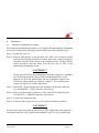
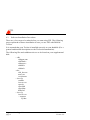
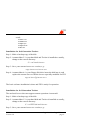
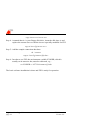
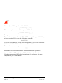
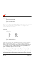
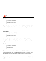
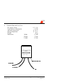
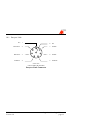
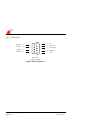
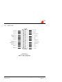
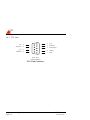
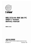
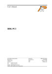
*-.User’s manual Ingenieurbüro Ingo Mohnen Rottstraße 33 52068 Aachen Germany Tel: +49 (241) 94924-0 Fax: +49 (241) 94924-29 E-Mail: [email protected] WWW: http://members.aol.com/impaachen Document: Document No.: Date: File: FIJI Manual DC9544001 October 30, 1995 fiji.wpd Copyrights and Warranties Ingenieurbüro Ingo Mohnen warrants the FIJI Centronics to link interface and cabling against defects in materials and workmanship for a period of one year from the date of original retail of purchase. This warranty does not apply if the product has been damaged by accident, abuse, misuse, or misapplication, has been modified without the written permission, or if the serial number has been removed or defaced. In no event will Ingenieurbüro Ingo Mohnen be liable for direct, indirect, special, incidential, or consequential damages resulting from any breach of warranty, or under any legal theory, including lost profits, downtime, goodwill, damage to or replacement of equipment and property, and any costs of recovering, reprogramming or reproducing any program or data used with FIJI. This manual and the software described in it are copyrigthed with all rights reserved. Under the copyright laws, this manual or the software may not be copied, in whole or part without written consent of Ingenieurbüro Ingo Mohnen, except in the normal use of the software or to make a backup copy. The same proprietary and copy right notices must be affixed to any permitted copies as were affixed to the original. This exception does not allow copies to be made for others, whether or not sold, but all material purchased with all (with all backup copies) may be sold, given or loaned to another person. The main parts of iserver.exe are property of INMOS Limited. FIJI Manual Version 3.0 Ingenieurbüro Ingo Mohnen page 1 Table of Contents General Description ........................................................................................... 4 System Requirements ........................................................................................ 5 Extent of supply................................................................................................. 6 Installation ......................................................................................................... 7 Hardware Installation Procedure ................................................................... 7 Software Installation Procedures................................................................... 8 Installation for 2nd Generation Toolset: ................................................... 9 Installation for 3rd Generation Toolset: .................................................... 9 Using FIJI ........................................................................................................ 11 Troubleshooting............................................................................................... 13 Creating your own server ................................................................................ 15 OpenLink:............................................................................................... 15 CloseLink:............................................................................................... 16 ReadLink: ............................................................................................... 16 WriteLink:............................................................................................... 17 ResetLink:............................................................................................... 18 AnalyseLink:........................................................................................... 18 TestError:................................................................................................ 18 TestRead: ................................................................................................ 19 TestWrite: ............................................................................................... 19 2nd generation Toolset iserver .................................................................... 20 3rd generation Toolset iserver..................................................................... 21 Testing a parallel port ...................................................................................... 22 Technical Data................................................................................................. 23 Connector Pinouts ........................................................................................... 24 Parsytec Link............................................................................................... 25 Hema Link................................................................................................... 26 MSC Link.................................................................................................... 27 TTL Link..................................................................................................... 28 Ingenieurbüro Ingo Mohnen page 2 FIJI Manual Version 3.0 FIJI Manual Version 3.0 Ingenieurbüro Ingo Mohnen page 3 1 General Description Congratulations on the purchase of your Centronis to Link Adapter FIJI! You are now owner of a highly developed adapter that enables interfacing between OS-Transputer-Links and a common Centronics data outlet as it is found with nearly all computing machines nowadays. FIJI provides a lot of sophisticated features: • External connection to standard printer port (especially interesting for Notebook/Laptop operation) • Various link standards supported • Hardware-implemented semaphore for multitasking operation • Interrupt-controlled operation supported • Software-switchable linkspeed (10 Mbps/20Mbps) • Data transfer rate up to 200 kBps • Adapted software upgrade for INMOS Toolset (2nd and 3rd Generation) • Basic software package for use in customers’ applications Any suggestions concerning the further improvement of this product are welcome. Feel free to send your comments to: Ingenieurbüro Ingo Mohnen Rottstraße 33 D-52068 Aachen Germany Fax: +49 (241) 94924-29 Ingenieurbüro Ingo Mohnen page 4 FIJI Manual Version 3.0 2 System Requirements • IBM AT/386/486 or compatible PC with parallel port • External keyboard connector DIN or MiniDIN supplying +5VDC • MS-DOS , version 3.3 or later It is assumed that the installer is familiar with the installation of hard- and software in PCs running MS-DOS. FIJI Manual Version 3.0 Ingenieurbüro Ingo Mohnen page 5 3 Extent of supply Before using this product, please carefully check that your package includes: • • • • • • FIJI Centronics to Link Adapter DIN MiniDIN converter MiniDIN DIN converter Test connector 3.5" disk User's manual Ingenieurbüro Ingo Mohnen page 6 FIJI Manual Version 3.0 4 4.1 Installation Hardware Installation Procedure The hardware installation procedure is very simple. During hardware installation be aware of electrostatic discharge! Please follow the steps outlined below: Step 1: Switch off your PC. Step 2: Plug in FIJI directly to the parallel port. Don’t use extension cables between FIJI and the parallel port since these may result in improper operation. Fasten FIJI by means of the attached screws. For this, insert a small screwdriver into the holes from the rear side of FIJI. Avoid unnecessary mechanical strain. CAUTION!!! Do not connect FIJI to the parallel port while the computer is switched on! Such an installation can put FIJI in an undefined state, result damage to FIJI or the parallel port. Do not by mistake connect your FIJI to any other connector available on the PC. PC's parallel ports always are Sub-D 25 female connectors! Step 3: Insert FIJI’s keyboard plug into the computer's keyboard connector. Use the MiniDIN DIN converter if necessary. Step 4: Insert your keyboard’s connector (if any) into FIJI’s keyboard jack. Use the DIN MiniDIN converter if necessary. Step 5: Connect the transputer link. Step 6: Switch on the system. Now you are ready to install the software. CAUTION!!! Do not power up your system without having FIJI connected to the computer’s keyboard connector. This could result in damage to FIJI or your parallel port. FIJI Manual Version 3.0 Ingenieurbüro Ingo Mohnen page 7 4.2 Software Installation Procedures There are a few steps to be taken before you start using FIJI. The following steps explain the software installation in case you use FIJI with INMOS Toolset. It is assumed that your Toolset is installed correctly on your harddisk (For a general and detailed description see the Toolset documentation). The following files and subdirectories are to be found on your supplemental disk: -- cbk cbkport.asm cbk2link.c cbkcport.c cbkutil.c cbkint.h --doc cbk_doc.txt news.txt revision.txt -- iserv2g readme iserver.exe speed.c speed.btl speed.bat hello.btl -- iserv3g iserver.exe -- connect fiji.dat Ingenieurbüro Ingo Mohnen page 8 FIJI Manual Version 3.0 --tools testacc.exe testtran.exe testpar.exe testsped.exe trans.exe Installation for 2nd Generation Toolset: Step 1: Make a backup copy of the disk. Step 2: Assumed that C: is your hard disk and Toolset is installed as usually, change to the correct directory: C:\>cd ictools\iserver Step 3: Save your current iserver.exe version, e.g.: copy iserver.exe iserver.sav Step 4: Assumed that A: is your floppy disk drive insert the disk into A: and replace the current iserver with the iserver especially modified for FIJI. copy a:\iserv2g\iserver.exe c: The basic software installation is done and FIJI is ready for operation. Installation for 3rd Generation Toolset: The enclosed iserver does not support remote operation via network! Step 1: Make a backup copy of the disk. Step 2: Assumed that C: is your hard disk and Toolset is installed as usually, change to the correct directory: C:\>cd D7314A\tools\iserver Step 3: Save your current iserver.exe version, e.g.: FIJI Manual Version 3.0 Ingenieurbüro Ingo Mohnen page 9 copy iserver.exe iserver.sav Step 4: Assumed that A: is your floppy disk drive, insert the disk into A: and replace the current iserver with the iserver especially modified for FIJI. copy a:\iserv3g\iserver.exe c: Step 5: Add the sample connection data base: cd ..\connect copy a:\iserv3g\connect\fiji.dat c: Step 6: In order to use FIJI, the environment variable ICONDB, which is usually set in autoexec.bat, must be redirected, e.g.: set ICONDB=c:\D7314A\connect\fiji.dat The basic software installation is done and FIJI is ready for operation. Ingenieurbüro Ingo Mohnen page 10 FIJI Manual Version 3.0 5 Using FIJI The enclosed software package provides all necessary functions of the INMOS Toolset in adapted form for your FIJI interface. So you can keep your familiar programming environment by simply exchanging some basic functions as described in chapter 7. There are several LEDs allowing the supervision of FIJI’s operation. Active LEDs have the following meaning: Busy (yellow): FIJI is busy due to attempts from any kind of software. Access from other software will be denied. Fast (yellow): Link speed is 20 Mbps. (LED ‘off’ means 10 Mbps) Send (green): One byte has been sent down the link and an acknowledge has not yet arrived. Receive (green): One byte has arrived from the link and can be read by the PC. Analyse (red): Analyse signal output is active. Error (red): Error signal input or Reset signal output is active. (See drawing in chapter 9 for LED's positions.) To establish a connection between your transputer environment and a host machine via FIJI you first have to tell the software tools where to find FIJI and which link speed is to be used. Default settings are: LPT1, 20 Mbps. If you use 2nd generation Toolset, other configurations are selectable by using a command line option in the following way: /sl {LPT_NO},{LINKSPEED},{ADAPTEROPTION} DOS can handle a maximum of three parallel ports. {LPT_NO}=(1,2,3) FIJI Manual Version 3.0 Ingenieurbüro Ingo Mohnen page 11 Commonly used link speeds are 10 or 20 Mbps. {LINKSPEED}=(10,20) There is one option to unconditionally reset FIJI before use. {ADAPTEROPTION}=(r,R) Example: To start the toolset compiler with FIJI at LPT2 using a link speed of 10 Mbps without resetting FIJI execute the following command: icc /sl 2,10 ... If you use 3rd generation Toolset, this configuration is part of the connection data base file fiji.dat. Refer to the comments given there. To start the toolset server type: iserver /sl fiji ... Ensure the correct hard- and software installation and start operation! At least the Error LED and the Busy LED should be active for a short moment. If nothing happens and FIJI refuses operation at all, don’t worry, the next chapter helps you to find the bug! Ingenieurbüro Ingo Mohnen page 12 FIJI Manual Version 3.0 6 Troubleshooting Although FIJI usually works fine after installation there might be certain circumstances which prevent FIJI from operating properly. The following checklist is provided to help you in overcoming some of the known problems. This guide, however, is not intended to be a repair manual. If you encounter problems other than those described here, please contact your dealer. Error message: "...Link hardware already in use" All LEDs are inactive. FIJI installed at the correct parallel port ? Power supply connected ? Modified iserver used ? What to do: Execute the program testacc.exe from your supplemental disk! This program reports the parallel ports found in your system and looks for an installed FIJI. If FIJI is located, a simple test is performed and the LEDs light up as described within the program. Otherwise FIJI or your parallel port might be damaged or incompatible with each other. Try another parallel port if possible or call for technical support. Those users familiar with hardware may check a parallel port according to chapter 8. Error message: "... unable to write byte ... to the boot link." At least the Busy LED flashes. FIJI is connected correctly to your parallel port but communication to your transputer network failed. Physical connection damaged or incompatible ? Refer to chapter 10. Link speeds match ? FIJI Manual Version 3.0 Ingenieurbüro Ingo Mohnen page 13 What to do: Attach the test connector to your FIJI’s link cable and execute the program testtran.exe from your supplemental disk! This program automatically locates your FIJI and performs an extended test including a link data path test: The LED’s built into the test connector flash repeatedly during test execution. If they won’t do so or other errors are detected by the program, FIJI may be damaged. Otherwise FIJI surely is not the reason for incorrect operation. Ingenieurbüro Ingo Mohnen page 14 FIJI Manual Version 3.0 7 Creating your own server In some cases it may be necessary to modify the standard iserver delivered with INMOS Toolset. In order to allow creating your own iserver for use with FIJI all basic I/O functions modified for FIJI usage are compatible with the standard I/O functions. Your supplemental disk includes these functions. The I/O module \cbk\cbk2link.c contains the following routines: OpenLink: int OpenLink (const char *Name) { return LinkIdOrFailure; } Make sure the link associated with Name is ready for reading and writing. The syntax of a link name is: Name = {LPT_NO},{LINKSPEED},{ADAPTEROPTION} DOS can handle a maximum of three parallel ports. {LPT_NO}=(1,2,3) Usual link speeds are 10 or 20 Mbps. {LINKSPEED}=(10,20) There is one option available to unconditionally reset FIJI before use. {ADAPTEROPTION}=(r,R) A positive return value (LinkId) identifies the link in subsequent operations. A negative return value indicates an error. FIJI Manual Version 3.0 Ingenieurbüro Ingo Mohnen page 15 CloseLink: int CloseLink (int LinkId) { return SuccessOrFailure; } Closes the active link specified by LinkId. No further actions can be performed on this link. CloseLink will return 0 if the link is successfully closed or a negative value if an error occurred. ReadLink: int ReadLink ( int LinkId, char *Buffer, int Count, int TimeOut ) { return NoOfBytesOrError; } Reads some data from a link. The Link is specified by the LinkId parameter, and the maximum number of bytes to be read is specified by the Count parameter. The Timeout parameter indicates the maximum amount of time to wait, in tenths of a second, for the read attempt to be completed. Buffer is a pointer to the buffer which is to receive the data. The return value from ReadLink indicates the outcome of the transfer as follows: A value equal to Count indicates that all bytes were successfully read from the link. A negative value indicates that an error occurred, in which case the bytes transferred (if any) are lost. A value within the range 0 to (Count -1) indicates that ReadLink timed out before completion and may be restarted. In Ingenieurbüro Ingo Mohnen page 16 FIJI Manual Version 3.0 this case the user’s buffer will contain the bytes read from the link, up to the number of bytes given by the return value of ReadLink. WriteLink: int WriteLink ( int LinkId, char *Buffer, int Count, int TimeOut ) { return NoOfBytesOrError; } Writes some data to a link. The Link is specified with the LinkId parameter, and the maximum number of bytes to be written is specified by the Count parameter. The Timeout parameter indicates the maximum amount of time to wait, in tenths of a second, for the write attempt to be completed. Buffer is a pointer to the buffer containing the data to be sent. The return value from WriteLink indicates the outcome of the transfer as follows. A value equal to Count indicates that all bytes were written to the link successfully. A negative value indicates that an error occurred, in which case the bytes transferred (if any) are lost. A value within the range 0 to (Count -1) indicates that WriteLink timed out before completion and may be restarted. In this case the data in the user’s buffer will have been written to the link, up to the number of bytes given by the return value of WriteLink. FIJI Manual Version 3.0 Ingenieurbüro Ingo Mohnen page 17 ResetLink: int ResetLink (int LinkId) { return SuccessOrFailure; } Resets the subsystem associated with the link specified by LinkId. ResetLink will return 0 if the subsystem’s reset was successful or a negative value if an error occured. AnalyseLink: int AnalyseLink (int LinkId) { return SuccessOrFailure; } Analyses the subsystem associated with the link specified by LinkId. AnalyseLink will return 0 if the subsystem has been analysed successfully or a negative code if an error occured. TestError: int TestError (int LinkId) { return ErrorFlag; } Tests the error status associated with the link specified by LinkId. TestError will return "true" (1) if the transputer error flag is set, "false" (0) if the transputer error flag is not set or a negative value if an error occurred. Ingenieurbüro Ingo Mohnen page 18 FIJI Manual Version 3.0 TestRead: int TestRead (int LinkId) { return DataPresentOrNot; } Tests the receive status associated with the link specified by LinkId. TestRead will return "true" (1) if data is ready to be read, "false" (0) if no data arrived on the link or a negative value if an error occurred. TestWrite: int TestWrite (int LinkId) { return LinkReadyToSendOrNot; } Tests the send status associated with the link specified by LinkId. TestWrite will return "true" (1) if the link is ready to receive data, "false" (0) if data has not yet been acknowleged or a negative value if an error occurred. If you need additional information, feel free to contact the manufacturer! FIJI Manual Version 3.0 Ingenieurbüro Ingo Mohnen page 19 7.1 2nd generation Toolset iserver (Microsoft C7.0 is required) To rebuild iserver.exe follow these steps: Step 1: Create a working subdirectory for all source files, e.g.: md c:\fiji Step 2: Create a working copy of the standard iserver source in the working subdirectory, e.g.: copy c:\ictools\source\iserver\*.* c:\fiji Step 3: Copy the source files from disk to a subdirectory, e.g.: copy a:\cbk\*.* c:\fiji Step 4: Edit iserver.c. Replace line 403 "if (*s = = NULL)" with "if (*s = = 0)" Step 5: Edit iserver.c. Delete line 40 "EXTERN int errno;" Step 6: Open iserver.mak as a project from MSC7.0 and rebuild iserver.exe For a general and detailed description see the MSC 7.0 documentation. Ingenieurbüro Ingo Mohnen page 20 FIJI Manual Version 3.0 7.2 3rd generation Toolset iserver Please contact the manufacturer if information concerning rebuilding of the 3rd generation iserver.exe is needed. FIJI Manual Version 3.0 Ingenieurbüro Ingo Mohnen page 21 8 Testing a parallel port A test of your parallel port requires a special test connector. You need a Sub-D 25 male with the following connections. Pin 15 to Pin 5 Pin 13 to Pin 6 Pin 12 to Pin 7 Pin 10 to Pin 8 Pin 11 to Pin 9 Attach this test connector to your parallel port and start the program testpar.exe from your supplemental disk. If the port does not work properly, errors will be reported. Ingenieurbüro Ingo Mohnen page 22 FIJI Manual Version 3.0 9 Technical Data and Case View DC supply voltage Typical power consumption Operating temperature Storage temperature Weight Dimensions 5 V ± 5% 1,25 W 0 - 50 C 0 - 70 C 100 g 53 mm 17 mm 65 mm Width Height Length Fast Sem Error Analyse Link In Link Out Ingo Mohnen Ingenieurbüro Aachen ,QVHUWVFUHZGULYHUKHUH .H\ERDUGSOXJ .H\ERDUGMDFN /LQN FIJI Manual Version 3.0 Ingenieurbüro Ingo Mohnen page 23 10 Connector Pinouts The following pages show all the connector pinouts for FIJI. The Centronics connector is common to all types, whereas the link connector used depends on the type of FIJI you have. Ingenieurbüro Ingo Mohnen page 24 FIJI Manual Version 3.0 10.1 Parsytec Link NC 1 ResetOut+ 8 NC 2 7 LinkIn+ ResetOut- 3 6 LinkIn- LinkOut+ 4 5 LinkOut- front view Lemosa EPG.1B.308.HLN Parsytec Link Connector FIJI Manual Version 3.0 Ingenieurbüro Ingo Mohnen page 25 10.2 Hema Link LinkOut- 9 notError 8 LinkIn- 7 notReset 6 5 Vcc 4 LinkOut+ 3 notAnalyse 2 LinkIn+ 1 Gnd front view Sub-D 9 female Hema Link Connector Ingenieurbüro Ingo Mohnen page 26 FIJI Manual Version 3.0 10.3 MSC Link 9FF Vcc 25 9FF Vcc 24 1& NC 23 /LQN2XW LinkOut- 22 LinkIn- 21 NC 20 NC 19 notReset- 18 notAnalyse- 17 notError- 16 Gnd 15 Gnd 14 /LQN,Q 1& 1& QRW5HVHW QRW$QDO\VH QRW(UURU 1& *QG *QG front view Sub-D 25 female MSC Link Connector FIJI Manual Version 3.0 Ingenieurbüro Ingo Mohnen page 27 10.4 TTL Link NC 9 notError 8 NC 7 notReset 6 5 Vcc 4 LinkOut 3 notAnalyse 2 LinkIn 1 Gnd front view Sub-D 9 female TTL Link Connector Ingenieurbüro Ingo Mohnen page 28 FIJI Manual Version 3.0