1
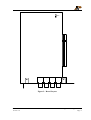
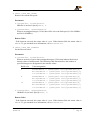
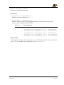
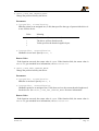
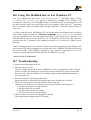
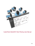
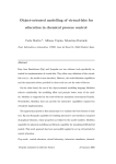
User’s Manual
BBK-PCI
Ingo Mohnen Ingenieurbüro
Rottstraße 33
52068 Aachen
Germany
Tel:
+49 (241) 54 19 01
Fax:
+49 (241) 53 68 36
E-Mail: [email protected]
WWW: http://members.aol.com/impaachen
Document:
Document No.:
Date:
File:
BBK-PCI Manual
DC9803002
March 4, 1998
bbkman.doc
Scope
This documentation refers to
• BBK-PCI expansion card of revision 1.1
• The BBK-PCI device driver for Windows NT of revision 0.4
• The 2nd generation Iserver for Windows NT of IMP modification 1.0
Copyrights And Warranties
Ingo Mohnen Ingenieurbüro warrants the BBK-PCI link interface and cabling against defects
in materials and workmanship for a period of one year from the date of original retail
purchase.
This warranty does not apply if the product has been damaged by accident, abuse, misuse, or
misapplication, has been modified without the written permission, or if the serial number has
been removed or defaced.
In no event will Ingo Mohnen Ingenieurbüro be liable for direct, indirect, special, incidental,
or consequential damages resulting from any breach of warranty, or under any legal theory,
including lost profits, downtime, goodwill, damage to or replacement of equipment and
property, and any costs of recovering, reprogramming or reproducing any program or data
used with BBK-PCI.
This manual and the software described in it are copyrighted with all rights reserved. Under
the copyright laws, this manual or the software may not be copied, in whole or part without
written consent of Ingo Mohnen Ingenieurbüro, except in the normal use of the software or to
make a backup copy. The same proprietary and copyright notices must be affixed to any
permitted copies as were affixed to the original. This exception does not allow copies to be
made for others, whether or not sold, but all material purchased with all (with all backup
copies) may be sold, given or loaned to another person.
The main parts of Iserver are property of SGS-Thomson Microelectronics Limited.
BBK-PCI User’s Manual
Version 1.0
Ingo Mohnen Ingenieurbüro
Page 2
Table Of Contents
I Hardware Description...............................................................................................................4
I.1 Introduction ...........................................................................................................................4
I.1.1 General Description............................................................................................................4
I.1.2 System Requirements .........................................................................................................4
I.1.3 Extent Of Supply ................................................................................................................5
I.1.4 Supported Link Standards ..................................................................................................5
I.1.5 Mechanical Outlines ...........................................................................................................5
I.2 Installation .............................................................................................................................7
I.3 BIOS Setup ............................................................................................................................8
I.4 Troubleshooting.....................................................................................................................8
I.5 Technical Data.......................................................................................................................8
I.6 Connector Pinout ...................................................................................................................9
II Using BBK-PCI with Windows NT......................................................................................10
II.1 Driver Installation ..............................................................................................................10
II.2 Driver Deinstallation ..........................................................................................................11
II.3 Customizing the Driver ......................................................................................................11
II.4 Starting and Stopping the Driver........................................................................................12
II.5 Writing Your Own Programs Using the Driver .................................................................13
II.5.1 Introduction .....................................................................................................................13
II.5.2 CreateFile ........................................................................................................................14
II.5.3 ReadFile ..........................................................................................................................16
II.5.4 WriteFile..........................................................................................................................17
II.5.5 DeviceIoControl ..............................................................................................................18
II.5.6 CloseHandle ....................................................................................................................26
II.5.7 Header Mode ...................................................................................................................26
II.6 Using The Modified Iserver For Windows NT..................................................................27
II.7 Troubleshooting .................................................................................................................27
BBK-PCI User’s Manual
Version 1.0
Ingo Mohnen Ingenieurbüro
Page 3
I Hardware Description
I.1
Introduction
I.1.1 General Description
Thank you for choosing the BBK-PCI as your OS link interface.
It is a smart transputer link interface providing both a fast and flexible connection between
four transputer OS links and another computer system via the PCI Bus. BBK-PCI is an
expansion board conforming to the PCI Bus specification rev. 2.0 and incorporates four link
connectors according to Parsytec’s UniLink standard.
A fully equipped transputer node built around a T425 processor is the board’s core; virtually
any T4 or T8 processor is applicable. It may be booted as well from the PCI side as, like
usual, from link. The user is free to apply BBK-PCI as a transparent link interface or to bind
the transputer node into his own network topology.
The BBK-PCI structure is optimized to sustain, in combination with an adequate protocol, a
data throughput corresponding to the bandwith of four fully saturated OS links. This is
achieved without exerting significant load on the host, since this adapter acts as a bus master
and transfers data between link and host memory via DMA under control of the on-board
transputer.
Hence BBK-PCI permits PCI-based computer systems to be bound equally into a transputer
network. So the usual topology consisting of a host on one side and a transputer network on
the other side can be turned into a system of totally different computer systems connected by
transputer links.
The BBK-PCI offers many sophisticated features:
•
•
•
•
•
•
•
DMA capable, thus allowing maximum speed with only a minimum CPU load
interrupt-controlled operation
driver for Windows NT included
full duplex operation
fully software-configurable as necessary for plug-and-play systems
link speed is software switchable between 10 Mbps and 20 Mbps
software upgrade for Inmos 2nd and 3rd gen. Toolset included
I.1.2 System Requirements
In order to use BBK-PCI you need a host equipped with an idle 5V/32-bit PCI slot
complying to PCI Bus specification 2.0 which is capable of bus mastering.
The driver for Windows NT requires a uniprocessor i386 architecture machine running
Microsoft Windows NT 3.51 or higher.
BBK-PCI User’s Manual
Version 1.0
Ingo Mohnen Ingenieurbüro
Page 4
I.1.3 Extent Of Supply
Before using this product, please carefully check that your package includes:
• BBK-PCI link interface
• 3.5" supplemental disk
I.1.4 Supported Link Standards
The BBK-PCI basically supports Parsytec’s UniLink standard, which incorporates Link Data
Input, Link Data Output, Link Reset Input, and Link Reset Output with four differential
RS-422 pairs per link. It can be optionally equipped with a 40-way header intended for
adapting different link standards to the interface.
Currently a B008 adapter is available from us, which makes BBK-PCI compatible with the
external link of an Inmos B008 motherboard. Please contact us if you need a special solution.
I.1.5 Mechanical Outlines
Link 0
Link 1
Link 2
Link 3
Figure 1 - Rear View
BBK-PCI User’s Manual
Version 1.0
Ingo Mohnen Ingenieurbüro
Page 5
Ju1
Figure 2 - Board Layout
BBK-PCI User’s Manual
Version 1.0
Ingo Mohnen Ingenieurbüro
Page 6
I.2 Installation
Although the hardware installation procedure is fairly simple be aware of static electricity.
Under the right conditions, static electricity will build up. If you touch the board or its
components it will discharge into the components and circuitry. Computer components are
sensitive to damage from electrostatic discharge. They can be damaged or destroyed if the
discharge is powerful enough. Static build-up is most likely to occur in dryer and cooler
conditions, but it is always important to be cautious.
To protect the link interface and other components against damage from electrostatic
discharge, you should follow some basic precautions whenever you handle them:
1. Use a grounding wrist strap. The strap will have an ‘alligator’ clip at the end of a shielded
wire lead. Clip it to a grounded object. Any static electricity will then harmlessly
discharge through the strap. Put on and connect the strap before you handle the
components and don’t forget to disconnect it before running to the phone.
2. Use an anti-static pad. Put any components on the pad whenever you work on them
outside the computer. If you don’t have a pad, use the anti-static bag BBK-PCI came in.
Both the wrist strap and pad are inexpensive and are generally available from computer
supply companies.
After having taken the precautions outlined above please follow the steps outlined below in
order to mount the BBK-PCI in your computer.
1. Switch off the machine and disconnect the power cord from the mains.
2. Open the computer’s case.
3. Determine an idle PCI slot into which BBK-PCI shall go. This has to be a master slot. Not
all PCI slots are necessarily master slots (consult your mainboard’s manual). There are
motherboards where you have to explicitly enable a slot’s bus master capability in the
BIOS setup. All other slot requirements demanded by BBK-PCI are met if it mechanically
fits into the slot connector.
4. Remove the slot cover from the slot you plan to use with BBK-PCI. Put the screw aside
and store the slot cover in a safe place in case you need it later.
5. Make sure that jumper Ju1 on BBK-PCI is seated as illustrated in Figure 2.
6. Align the board’s edge connector to the slot connector and gently push BBK-PCI into
place. Do not use excessive force, it should insert easily.
7. Attach BBK-PCI’s mounting bracket to the computer case using the mounting screw you
put aside earlier.
8. Shut the computer’s case.
9. Connect the power cord to the mains, plug in your transputer system’s link connectors.
10. Start the system and change the BIOS setup.
BBK-PCI User’s Manual
Version 1.0
Ingo Mohnen Ingenieurbüro
Page 7
I.3 BIOS Setup
The computer’s BIOS needs to be set up correctly in order to make hardware and software
work properly. Unfortunately, the options provided by different BIOS manufacturers differ
significantly, making it impossible to give detailed explanations for specific boards.
• The interrupt mapping for PCI devices is usually done automatically by the BIOS and
should work without user intervention on PCI-only boards. If the board has additional ISA
or EISA slots, the BIOS must be manually informed about the interrupt lines that will be
used by ISA or EISA boards. Otherwise an inadverted interrupt sharing between ISA
boards and PCI boards may occur, preventing the BBK-PCI driver from starting because it
can not allocate its interrupt line.
• Enabling PCI Concurrency allows the CPU to operate while the PCI bus is active. If this is
not enabled, the CPU will experience a performance loss during data transfers.
• PCI Streaming or CPU to PCI burst both determine whether CPU bursts will be split up
into multiple accesses on the PCI bus. This parameter is not particularly important for this
driver, but it may improve overall system performance somewhat if enabled.
• PCI bursts should be enabled if possible to minimize PCI bus load.
• The PCI Latency Timer determines the possible length of PCI bursts. Longer bursts will
result in higher PCI throughput. It should not be set to less than 10 for a BBK-PCI.
• The BBK-PCI needs to become bus master. Make sure it is placed in a slot with bus master
capability and enable it if necessary.
I.4 Troubleshooting
Common pitfalls are:
• Physical connection incorrect or damaged
• The link speeds on either side of the link do not match
I.5 Technical Data
DC supply voltage
Card type
Size
Power consumption
Operating temperature
Rel. humidity
Storage temperature
Links
BBK-PCI User’s Manual
Version 1.0
5 V ± 5%
PCI Bus rev. 2.0 expansion card
5V, 32-bit, bus master
PCI short, 6.875" × 4.2"
7.5 W
0 – 40 °C
20 – 80%, non-condensing
0 – 70 °C
4 OS links Parsytec UniLink
optional 40-way adapter connector
10 / 20 Mb/s
Ingo Mohnen Ingenieurbüro
Page 8
I.6 Connector Pinout
Figure 3 shows the pinout for the BBK-PCI Parsytec UniLink connectors. The link
connectors your BBK-PCI actually has may differ from that, if you have a special adapter
attached to the optional adapter connector.
ResetIn+
1
ResetOut+
8
ResetIn-
2
7
LinkIn+
ResetOut-
3
6
LinkIn-
LinkOut+
4
5
LinkOut-
Front View
Lemosa EPG.1B.308.HLN
Figure 3 - Parsytec UniLink Connector
The matching cable connector is the Lemo FGG.1B.308.CLAD. It can be ordered from
Lemo Elektronik GmbH
Stahlgruberring 7
81829 München
Germany
Phone+49 (89) 42 30 85
Fax+49 (89) 4 20 21 92
Readily made link cables suitable for BBK-PCI can also be obtained from us if you specify
your requirements. Please contact us.
BBK-PCI User’s Manual
Version 1.0
Ingo Mohnen Ingenieurbüro
Page 9
II Using BBK-PCI with Windows NT
II.1 Driver Installation
At this point you will need the supplemental disk. The contents of the directories relevant to
the Windows NT driver installation are described here.
DOC
README.TXT
TRANSP
BLKTST.BTL
NT
DRIVER
REGINI.EXE
LINK.H
BBKPCI.INI
BBKPCI.SYS
ISERVER.2G
ISERVER.EXE
SOURCE
SAMPLES
IOCTL.C
IOCTL.EXE
PEEK.C
PEEK.EXE
POKE.C
POKE.EXE
Latest documentation not contained here
Block transfer test bootable
This program sets up the registry using the data supplied
in the file BBKPCI.INI
C Header file containing definitions needed to compile
programs accessing the driver
Registry default values
The driver executable
2nd generation Iserver for Windows NT
Directory containing the Iserver source files
Sample application: ioctl call
Sample application: peek transputer
Sample application: poke transputer
To install the new driver on a computer running Windows NT administrator rights are
required. Perform these steps:
1. Make a backup copy of the supplemental disk, if you have not done so yet.
2. From a command prompt change your working directory to \NT\DRIVER on the
supplemental disk and run the command
regini bbkpci.ini
This sets up new registry values needed by NT and the driver.
3. Do
copy bbkpci.sys %SystemRoot%\system32\drivers
This copies the driver executable to the Windows directory.
4. Reboot the machine.
BBK-PCI User’s Manual
Version 1.0
Ingo Mohnen Ingenieurbüro
Page 10
II.2 Driver Deinstallation
To remove this driver from the system, you need to remove the driver executable file
%SystemRoot%\system32\drivers\bbkpci.sys
You also need to remove all registry entries that belong to this driver. Remove
HKEY_LOCAL_MACHINE/
SYSTEM/
CurrentControlSet/
Services/
bbkpci
and
HKEY_LOCAL_MACHINE/
SYSTEM/
CurrentControlSet/
Services/
EventLog/
System/
bbkpci
using the Windows NT program regedt32. Having done this, the driver is completely
removed from the system.
II.3 Customizing the Driver
The driver reads several values from registry on startup determining its behaviour at runtime.
Some values may be changed through ioctl functions at runtime, others may not. The
installation procedure sets default values for all registry values. If you do not like these
defaults, you may change them using the Windows NT program regedt32. This progam is
part of Windows NT, just type
regedt32
The values can be found under
HKEY_LOCAL_MACHINE/
SYSTEM/
CurrentControlSet/
Services/
bbkpci/
Parameters/
Devicen
The BBK-PCI driver uses these values:
BBK-PCI User’s Manual
Version 1.0
Ingo Mohnen Ingenieurbüro
Page 11
Name
ReadTimeout
Meaning
The timeout in ms used by ReadFile.
WriteTimeout
The timeout in ms used by WriteFile.
IoctlTimeout
The timeout in ms used by DeviceIoControl.
LinkSpeed
This parameter defines the link speed used by the
driver. You may specify 10 (0xA) or 20 (0x14).
the default is 20.
HeaderMode
You may specify values 0 through 3. If this
parameter is set to 0, the driver will use stream
mode. If it is set to 1 through 3, header mode will
be used. The value then specifies the desired
header length. Default is to use stream mode.
Note that changes you make will not take effect before the driver is started next time.
II.4 Starting and Stopping the Driver
Once the driver is installed on your system, it must also be started before you can use it. You
can do this either by typing
net start bbkpci
or by using the Control Panel/Devices. Select BBKPCI and click the Start button. Note that
the driver will refuse to start if it encounters any problems. See the chapter Troubleshooting
on page 27 for more information.
During the boot process, Windows NT can start drivers automatically. In order to have the
BBK-PCI driver started automatically, you need to change its startup type. This is done using
the Control Panel/Devices. Select BBKPCI and click the Startup button. Then select
Automatic as the desired startup type.
It is not recommended to change the startup type to automatic before having verified that the
driver starts cleanly by starting the driver manually and checking whether Windows NT’s
event viewer indicates any driver related problems.
Unless the startup type is set to automatic, you have to start the driver manually each time
the machine is rebooted.
The driver can be stopped either by typing
net stop bbkpci
or by using the Control Panel/Devices. Select BBKPCI and click the Stop button.
Note that it is not necessary to stop the driver before shutting down the machine.
BBK-PCI User’s Manual
Version 1.0
Ingo Mohnen Ingenieurbüro
Page 12
II.5 Writing Your Own Programs Using the Driver
II.5.1 Introduction
Windows NT supports a fairly generic interface to allow communication between user
programs and device drivers. It uses the same function calls that are used to do file I/O.
Devices are separated from common files by reserving a separate name space for them. A
device name has the form \\.\NameIndex, with Name identifying the driver and Index
identifying the specific device controlled by this driver. The Name that has to be specified to
access the BBK-PCI driver is link. Index is 1 for the first BBK-PCI link, 2 for the second,
and so on. Note that the C notation for a single backslash in a string is "\\", so the name of
the first link of the first board becomes "\\\\.\\link1" and the name for the first link of
the second board becomes "\\\\.\\link5".
If your program wants to perform driver specific I/O control functions using
DeviceIoControl, it needs to include the file link.h.
The BBK-PCI driver supports full duplex operation. Each device may be opened by multiple
threads simultaneously. Multiple threads may call ReadFile and WriteFile
simultaneously. The driver serializes these calls maintaining full duplex operation. Calls to
DeviceIoControl are also serialized, they are executed as soon as neither a read nor a
write operation are pending.
BBK-PCI User’s Manual
Version 1.0
Ingo Mohnen Ingenieurbüro
Page 13
II.5.2 CreateFile
The CreateFile function opens a device. It returns a handle that can be used to access the
device.
HANDLE CreateFile (LPCTSTR lpDeviceName,
DWORD dwDesiredAccess,
DWORD dwShareMode,
LPSECURITY_ATTRIBUTES lpSecurityAttributes,
DWORD dwCreationDistribution,
DWORD dwFlagsAndAttributes,
HANDLE hTemplateFile);
Parameters
• lpDeviceName
Points to a null-terminated string that specifies the name of the device to open.
• dwDesiredAccess
Specifies the type of access to the device. An application can obtain read access, write
access, read-write access, or device query access. You can use the following flag constants
to build a value for this parameter. Both GENERIC_READ and GENERIC_WRITE must be
set to obtain read-write access.
Value
Meaning
0
Allows an application to query device
attributes without actually accessing the
device
GENERIC_READ
Specifies read access to the device
GENERIC_WRITE
Specifies write access to the file
• dwShareMode
Specifies how this device can be shared. This parameter must be some combination of the
following values:
Value
Meaning
0
Prevents the device from being shared
FILE_SHARE_READ
Other open operations can be performed
on the device for read access
FILE_SHARE_WRITE
Other open operations can be performed
on the device for write access
BBK-PCI User’s Manual
Version 1.0
Ingo Mohnen Ingenieurbüro
Page 14
• lpSecurityAttributes
Is only meaningful for file systems. Specify NULL when opening devices.
• dwCreationDistribution
You must specify OPEN_EXISTING when opening devices.
• dwFlagsAndAttributes
You must specify 0 when opening devices.
• hTemplateFile
You must specify NULL when opening devices.
Return Value
If the function succeeds, the return value is an open handle to the specified device. If the
function fails, the return value is INVALID_HANDLE_VALUE. To get extended error
information, call GetLastError.
BBK-PCI User’s Manual
Version 1.0
Ingo Mohnen Ingenieurbüro
Page 15
II.5.3 ReadFile
The ReadFile function reads data from a device. The device handle must have been
created with GENERIC_READ access to the device.
BOOL ReadFile (HANDLE hDevice,
LPVOID lpBuffer,
DWORD nNumberOfBytesToRead,
LPDWORD lpNumberOfBytesRead,
LPOVERLAPPED lpOverlapped);
Parameters
• hDevice
Identifies the device to be read. Call the CreateFile function to obtain a device handle.
• lpBuffer
Points to the buffer that receives the data read from the device. This buffer must be
DWORD aligned.
• nNumberOfBytesToRead
Specifies the number of bytes to be read from the device. It is an error to specify values
that are not divisible by four.
• lpNumberOfBytesRead
Points to the number of bytes read. ReadFile sets this value to zero before doing any
work or error checking.
• lpOverlapped
You must specify NULL when accessing devices.
Return Value
If the function succeeds, the return value is TRUE. If the function fails, the return value is
FALSE. To get extended error information, call GetLastError.
Remarks
Applications must not read from nor write to the input buffer that a read operation is using
until the read operation completes. A premature access to the buffer may lead to corruption of
the data read into that buffer.
The ReadFile function may fail and return ERROR_INVALID_USER_BUFFER or
ERROR_NOT_ENOUGH_MEMORY whenever there are too many outstanding asynchronous
I/O requests.
BBK-PCI User’s Manual
Version 1.0
Ingo Mohnen Ingenieurbüro
Page 16
II.5.4 WriteFile
The WriteFile function writes data to a device. The device handle must have been
created with GENERIC_WRITE access to the device.
BOOL WriteFile (HANDLE hDevice,
LPCVOID lpBuffer,
DWORD nNumberOfBytesToWrite,
LPDWORD lpNumberOfBytesWritten,
LPOVERLAPPED lpOverlapped);
Parameters
• hDevice
Identifies the device to be written to. Call the CreateFile function to obtain a device
handle.
• lpBuffer
Points to the buffer containing the data to be written to the device. This buffer must be
DWORD aligned.
• nNumberOfBytesToWrite
Specifies the number of bytes to write to the device. It is an error to specify values that are
not divisible by four.
• lpNumberOfBytesWritten
Points to the number of bytes written by this function call. WriteFile sets this value to
zero before doing any work or error checking.
• lpOverlapped
You must specify NULL when accessing devices.
Return Value
If the function succeeds, the return value is TRUE. If the function fails, the return value is
FALSE. To get extended error information, call GetLastError.
Remarks
Applications must not read from nor write to the input buffer that a write operation is using
until the write operation completes. A premature access to the buffer may lead to corruption
of the data written to the device.
The WriteFile function may fail with ERROR_INVALID_USER_BUFFER or
ERROR_NOT_ENOUGH_MEMORY whenever there are too many outstanding asynchronous
I/O requests.
BBK-PCI User’s Manual
Version 1.0
Ingo Mohnen Ingenieurbüro
Page 17
II.5.5 DeviceIoControl
The DeviceIoControl function sends a control code directly to a specified device
driver, causing the corresponding device to perform the specified operation.
BOOL DeviceIoControl (HANDLE hDevice,
DWORD dwIoControlCode,
LPVOID lpInBuffer,
DWORD nInBufferSize,
LPVOID lpOutBuffer,
DWORD nOutBufferSize,
LPDWORD lpBytesReturned,
LPOVERLAPPED lpOverlapped);
Parameters
• hDevice
Handle to the device that is to perform the operation. Call the CreateFile function to
obtain a device handle.
• dwIoControlCode
Specifies the control code for the operation. This value identifies the specific operation to
be performed and the type of device on which the operation is to be performed. Each
device driver may define its own set of values.
• lpInBuffer
Pointer to a buffer that contains the data required to perform the operation. This parameter
can be NULL if the dwIoControlCode parameter specifies an operation that does not
require input data.
• nInBufferSize
Specifies the size, in bytes, of the buffer pointed to by lpInBuffer.
• lpOutBuffer
Pointer to a buffer that receives the operation’s output data. This parameter can be NULL if
the dwIoControlCode parameter specifies an operation that does not produce output
data.
• nOutBufferSize
Specifies the size, in bytes, of the buffer pointed to by lpOutBuffer.
• lpBytesReturned
Pointer to a variable that receives the size, in bytes, of the data stored into the buffer
pointed to by lpOutBuffer. This parameter cannot be NULL. Even when an operation
produces no output data, and lpOutBuffer can be NULL, the DeviceIoControl
function makes use of the variable pointed to by lpBytesReturned. After such an
operation, the value of the variable is without meaning.
BBK-PCI User’s Manual
Version 1.0
Ingo Mohnen Ingenieurbüro
Page 18
• lpOverlapped
You must specify NULL when accessing device drivers.
Return Value
If the function succeeds, the return value is TRUE. If the function fails, the return value is
FALSE. To get extended error information, call GetLastError.
Remarks
The driver specific values for dwIoControlCode are defined in the file link.h, which must
be included by your source code if you want to perform calls to DeviceIoControl.
Legal values for dwIoControlCode are:
• IOCTL_LINK_RESET_LINK
Resets the BBK-PCI board, the link and any transputer node attached to it.
Parameters
• lpInBuffer, nInBufferSize
InBuffer is not used. Specify NULL, 0.
• lpOutBuffer, nOutBufferSize
OutBuffer is not used. Specify NULL, 0.
Return Value
If the function succeeds, the return value is TRUE. If the function fails, the return value is
FALSE. To get extended error information, call GetLastError.
• IOCTL_LINK_RESET_INTERFACE
Resets the BBK-PCI board but not the link.
Parameters
• lpInBuffer, nInBufferSize
InBuffer is not used. Specify NULL, 0.
• lpOutBuffer, nOutBufferSize
OutBuffer is not used. Specify NULL, 0.
Return Value
If the function succeeds, the return value is TRUE. If the function fails, the return value is
FALSE. To get extended error information, call GetLastError.
BBK-PCI User’s Manual
Version 1.0
Ingo Mohnen Ingenieurbüro
Page 19
• IOCTL_LINK_GET_INFO
Retrieves the driver revision and information about the BBK-PCI hardware from the
driver.
Parameters
• lpInBuffer, nInBufferSize
InBuffer is not used. Specify NULL, 0.
• lpOutBuffer, nOutBufferSize
OutBuffer points to an array of characters. This array will be filled with a \0-terminated
C-string containing the desired information. OutBuffer could look like this:
driver V2.0\n
serno E00000000023\0
Return Value
If the function succeeds, the return value is TRUE. The function fails if the caller supplied
insufficient space to hold the string. The return value will then be FALSE. To get extended
error information, call GetLastError.
• IOCTL_LINK_GET_CONFIG
Read one byte from the BBK-PCI configuration EEPROM.
Parameters
• lpInBuffer, nInBufferSize
Points to an unsigned integer (32 bit) that specifies the EEPROM address that is to be
read.
• lpOutBuffer, nOutBufferSize
Points to an unsigned integer (32 bit) that will be filled with the data byte read.
Return Value
If the function succeeds, the return value is TRUE. The function fails if the caller supplied
insufficient space for OutBuffer. The return value will then be FALSE. To get extended
error information, call GetLastError.
BBK-PCI User’s Manual
Version 1.0
Ingo Mohnen Ingenieurbüro
Page 20
• IOCTL_LINK_SET_CONFIG
Write one byte to the BBK-PCI configuration EEPROM.
Parameters
• lpInBuffer, nInBufferSize
Points to an array of two unsigned integers (32 bit each). The first element contains the
EEPROM address that is to be written, the second element contains the data.
• lpOutBuffer, nOutBufferSize
OutBuffer is not used. Specify NULL, 0.
Return Value
If the function succeeds, the return value is TRUE. If the function fails, the return value is
FALSE. To get extended error information, call GetLastError.
Remarks
You should probably never use this function. If you do, take care. If the function is used
improperly, the board may become permanently unusable.
• IOCTL_LINK_TEST_READ
Retrieve the number of characters that are already read from the link and can therefore be
fetched by a ReadFile with virtually no delay.
Parameters
• lpInBuffer, nInBufferSize
InBuffer is not used. Specify NULL, 0.
• lpOutBuffer, nOutBufferSize
Points to an unsigned integer (32 bit) that will be set to the number of characters.
Return Value
If the function succeeds, the return value is TRUE. If the function fails, the return value is
FALSE. To get extended error information, call GetLastError.
Remarks
Since the BBK-PCI uses a C012 which does not provide any FIFOs, this driver will only
return the numbers 0 (if no character arrived yet) or 1 (if a character has arrived), but no
other value. Drivers for other hardware may still return higher numbers.
BBK-PCI User’s Manual
Version 1.0
Ingo Mohnen Ingenieurbüro
Page 21
• IOCTL_LINK_TEST_WRITE
Retrieve the number of characters the hardware will accept without actually having to wait
for the receiving node to acknowledge anything.
Parameters
• lpInBuffer, nInBufferSize
InBuffer is not used. Specify NULL, 0.
• lpOutBuffer, nOutBufferSize
Points to an unsigned integer (32 bit) that will be set to the number of characters.
Return Value
If the function succeeds, the return value is TRUE. If the function fails, the return value is
FALSE. To get extended error information, call GetLastError.
Remarks
Since the BBK-PCI uses a C012 which does not provide any FIFOs, this driver will only
return the numbers 0 (if no character can be written currently) or 1 (if a character can be
written), but no other value. Drivers for other hardware may still return higher numbers.
• IOCTL_LINK_SET_SPEED
Change the link speed.
Parameters
• lpInBuffer, nInBufferSize
Points to an unsigned integer (32 bit) indicating the new link speed (10 for 10MBit/s or
20 for 20MBit/s).
• lpOutBuffer, nOutBufferSize
OutBuffer is not used. Specify NULL, 0.
Return Value
If the function succeeds, the return value is TRUE. If the function fails, the return value is
FALSE. To get extended error information, call GetLastError.
BBK-PCI User’s Manual
Version 1.0
Ingo Mohnen Ingenieurbüro
Page 22
• IOCTL_LINK_GET_SPEED
Retrieve the current link speed.
Parameters
• lpInBuffer, nInBufferSize
InBuffer is not used. Specify NULL, 0.
• lpOutBuffer, nOutBufferSize
Points to an unsigned integer (32 bit) that will be set to the link speed (10 for 10MBit/s
and 20 for 20MBit/s).
Return Value
If the function succeeds, the return value is TRUE. If the function fails, the return value is
FALSE. To get extended error information, call GetLastError.
• IOCTL_LINK_SET_TIMEOUT
Set the timeout values.
Parameters
• lpInBuffer, nInBufferSize
Points to an array of one to three unsigned integers (32 bit) that indicate the desired
timeout values in milliseconds. The following table illustrates how the number of
specified integers are designated to the timeout values.
Buffer size
Value designation
4
ReadTimeout = ((unsigned int*)lpInBuffer)[0]
WriteTimeout = ((unsigned int*)lpInBuffer)[0]
IoctlTimeout = ((unsigned int*)lpInBuffer)[0]
8
ReadTimeout = ((unsigned int*)lpInBuffer)[0]
WriteTimeout = ((unsigned int*)lpInBuffer)[1]
IoctlTimeout = ((unsigned int*)lpInBuffer)[0]
12
ReadTimeout = ((unsigned int*)lpInBuffer)[0]
WriteTimeout = ((unsigned int*)lpInBuffer)[1]
IoctlTimeout = ((unsigned int*)lpInBuffer)[2]
• lpOutBuffer, nOutBufferSize
OutBuffer is not used. Specify NULL, 0.
Return Value
If the function succeeds, the return value is TRUE. If the function fails, the return value is
FALSE. To get extended error information, call GetLastError.
BBK-PCI User’s Manual
Version 1.0
Ingo Mohnen Ingenieurbüro
Page 23
• IOCTL_LINK_GET_TIMEOUT
Retrieve the current timeout value.
Parameters
• lpInBuffer, nInBufferSize
InBuffer is not used. Specify NULL, 0.
• lpOutBuffer, nOutBufferSize
Points to an array of one to three unsigned integers (32 bit) that will be set to the
timeout values in milliseconds as follows:
Buffer size
Value designation
4
((unsigned int*)lpInBuffer)[0] = ReadTimeout
8
((unsigned int*)lpInBuffer)[0] = ReadTimeout
((unsigned int*)lpInBuffer)[1] = WriteTimeout
12
((unsigned int*)lpInBuffer)[0] = ReadTimeout
((unsigned int*)lpInBuffer)[1] = WriteTimeout
((unsigned int*)lpInBuffer)[2] = IoctlTimeout
Return Value
If the function succeeds, the return value is TRUE. If the function fails, the return value is
FALSE. To get extended error information, call GetLastError.
BBK-PCI User’s Manual
Version 1.0
Ingo Mohnen Ingenieurbüro
Page 24
• IOCTL_LINK_SET_HEADER_MODE
Change the protocol used by the driver.
Parameters
• lpInBuffer, nInBufferSize
InBuffer points to an unsigned int (32 bit) that specifies the type of protocol the driver is
to use for this device.
Value
Meaning
0
The driver will use stream mode
1
2
3
The driver will use header mode.
Value specifies the header length in bytes.
• lpOutBuffer, nOutBufferSize
OutBuffer is not used. Specify NULL, 0.
Return Value
If the function succeeds, the return value is TRUE. If the function fails, the return value is
FALSE. To get extended error information, call GetLastError.
• IOCTL_LINK_TEST_HEADER_MODE
Change the protocol used by the driver.
Parameters
• lpInBuffer, nInBufferSize
InBuffer is not used. Specify NULL, 0.
• lpOutBuffer, nOutBufferSize
OutBuffer points to an unsigned int (32 bit) that receives the current header length used
for the device. See IOCTL_LINK_SET_HEADER_MODE for more information.
Return Value
If the function succeeds, the return value is TRUE. If the function fails, the return value is
FALSE. To get extended error information, call GetLastError.
BBK-PCI User’s Manual
Version 1.0
Ingo Mohnen Ingenieurbüro
Page 25
II.5.6 CloseHandle
The CloseHandle function closes an open object handle.
BOOL CloseHandle (HANDLE hObject);
Parameters
• hObject
Identifies an open object handle.
Return Value
If the function succeeds, the return value is TRUE. If the function fails, the return value is
FALSE. To get extended error information, call GetLastError.
Remarks
CloseHandle invalidates the specified object handle, decrements the object’s handle
count, and performs object retention checks. Once the last handle to an object is closed, the
object is removed from the operating system. Use CloseHandle to close handles returned
by calls to the CreateFile function. Closing an invalid handle raises an exception. This
includes closing a handle twice, not checking the return value and closing an invalid handle,
and using CloseHandle on a handle returned by FindFirstFile.
II.5.7 Header Mode
During normal operation, the driver does not implement any additional protocol. The link
simply looks like a stream device. Since OS links are very often used in conjunction with the
ISERVER protocol defined by INMOS, this protocol was implemented into the driver,
thereby reducing the number of driver calls needed for data transfers. The ISERVER protocol
divides the data into variable size chunks. Each chunk of data is preceeded by a fixed length
header containing the number of data bytes following. For ISERVER, the header is always 2
bytes long, allowing up to 64 KB of data in each block. For additional flexibility, the driver
allows header lengths of 1, 2 and 3 bytes.
BBK-PCI User’s Manual
Version 1.0
Ingo Mohnen Ingenieurbüro
Page 26
II.6 Using The Modified Iserver For Windows NT
On your supplemental disk there is an Iserver for the 2nd generation Inmos Toolset
(\ISERVER.2G\ISERVER.EXE) which is modified for running in the Windows NT
environment. This Iserver uses the BBK-PCI driver for Windows NT or any other driver with
the same interface and is not specifically tied to the hardware. Note that the 2nd generation
Iserver is capable of also serving bootables compiled with the 3rd generation Inmos Toolset in
most cases.
In order to use the Iserver for Windows NT you should rename the original Iserver contained
in the Inmos Toolset (usually in \ICTOOLS\ISERVER), e.g. to ISERVER.ORG and then
copy the upgraded Iserver from the supplemental disk to the Toolset Iserver directory. You
may alternatively choose to execute the Iserver for Windows NT from any other directory,
provided this one is included in the standard execution PATH before the original Iserver
directory.
When invoking the Iserver for Windows NT the link name parameter gets the Windows NT
device name of the link you intend to use, which in the case of BBK-PCI is linkn with n being
the current number of the BBK-PCI installed in your computer, beginning at one. So for
instance to boot the blocktest bootable from the first BBK-PCI you type
iserver /sl link1 /sb blktst.btl
II.7 Troubleshooting
Common errors that might occur are:
• The driver does not start
The driver might not be able to detect a BBK-PCI board or it might not be able to allocate
resources (either port addresses or an interrupt). Ensure the board is properly seated and
fixed in its slot. Also, the Windows NT event log might contain valuable information to
solve this problem.
• The driver cannot be opened by applications
Ensure the driver is started and you supplied the correct filename to CreateFile.
• The device can be opened, but data transfers always time out
Timeouts occur if there was no interrupt after the specified time. This happens if
• the link connection is wrong or broken
• the link speeds do not match
• the other side does not accept data
• the PCI slot is not bus master capable
• The driver does not achieve the throughput it should
This might indicate inappropriate PCI settings.
BBK-PCI User’s Manual
Version 1.0
Ingo Mohnen Ingenieurbüro
Page 27