1
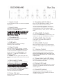
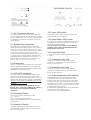
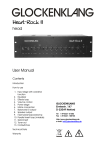
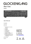
head
User Manual
Contents
Introduction
How to use
1. Input stage with overdrive
function
2. Tuner out
3. Equalizer
4. Effects loop
5. Volume control
6. Power stage
7. Mains connection
8. Speaker + phones outputs
9. Balanced DI output
10. Parallel insert loop (mixable)
including MP3 player input
11. Footswitches
12. DIP-switches for outputimpedance
Technical Data
Warranty
GLOCKENKLANG
Eimterstr. 147
D-32049 Herford
Tel +49-5221-51506
Fax +49-5221-108755
http://www.glockenklang.de
e-mail: [email protected]
Thank you for choosing the
GLOCKENKLANG Blue Sky amplifier. You
have purchased an exquisite piece of
equipment, which was designed after the
most modern technical aspects.
Attention!
To activate your additional 3 years
warranty, you should send in the enclosed
warranty card.
Please enter the serial number of your
amplifier and the date of purchase and
send it to:
Glockenklang
Eimterstrasse 147
D-32049 Herford
Germany
or email to: [email protected]
WARNING!
DO NOT OPEN!
NO USER SERVICEABLE PARTS
INSIDE.
REFER SERVICING TO QUALIFIED
PERSONNEL.
Care
Use a soft, clean and dry cloth only to
clean the amplifier. Do not use aggressive
chemicals to clean the housing. Do not
use compressed air to clean the housing.
You may carefully vacuum the air intake
and exhaust areas from time to time to
remove loose dust accumulation.
Please, keep this User Manual for
future references
General instructions
This serves as a measure to ensure
excellent customer service in the
future.
For your safety
Your Blue Sky head´s special features:
On the left side you can adjust the
level of the “DI-Out” with a screw-driver!
Do not operate the amplifier under the
following conditions:
"Effect Loop" is a parallel loop with
blending control from 0% till 100% on the
front panel and gain control ±5 dB of
Effect Return. Additional, you can use the
Effect Return either as a mixable Line In or
as a stereo MP3 players input.
It is switched post eq / pre volume-control/
pre-DI out.
In direct sunlight
In extremely dirty or dusty places
In extremely humid or wet places
Around heat emitting appliances
The power amp is short circuit, high
temperature and DC voltage protected.
In case of high temperature or DC
current, the red "Protect" LED will come on.
Please read the following instructions
carefully. These tips will ensure long and
trouble free operation of your new
GLOCKENKLANG product.
Operational restrictions
•
•
•
•
Caution: When rack mounting the
amplifier, make sure to leave adequate
room for ventilation. The unit needs this
ventilation space to adequately exhaust
it´s internally generated heat.
Handling
Do not drop the amp. Do not use
excessive force when activating switches
and dials.
Caution!
Due to safe ventilation, do not remove
the bumpers on the bottom of the amp!
Please ensure adequate ventilation when
rack mounting the amplifier.
Leave a minimum of 5 mm space below
the amplifier. Make sure that the air
entry/discharge vents at the right side of
the housing and the bottom are
unobstructed.
Caution!
For optimum sound use always the
included high-end mains cable!
WARNING!
TO REDUCE THE RISC OF FIRE OR
ELECTRIC SHOCK, DO NOT EXPOSE
THIS EQUIPMENT TO RAIN OR MOISTURE.
1.1 Input A Jack
3.1 Equalizer with On Switch
Normal instrument input for active and passive
instruments.
Bass, Low, Mid, Mid-KHz and Treble controls
serve to fine tune your sound or solve
acoustical problems on stage. They will be
activated by the On Switch. The mid eq is a
semi-parametric one. The frequencies are
centered at 60 Hz, 130 Hz, 200 Hz - 4 KHz and
8 KHz.
1.2 Input B Jack
Instrument input for high level instruments.
Adjustable via Input B Trim knob.
As a general rule, the trim pot should not be
used to attenuate the input signal so much
that the gain control has to be set higher
than 5 (twelve o'clock).
1.3 Overdrive LED
Illuminates when the signal of the preamp
begins to clip (overdrive).
1.4 A/B Switch
Activates Input A or Input B, enabling
switching of two instruments.
1.5 Gain Control
Matches input signal to preamp. To adjust,
turn knob until the Overdrive LED beside the
control only flickers at highest and loudest
peaks. The level in the Effect Loop is then
adjusted to +4 dB and the headroom to
overdrive is 20 dB.
For overdrive function, give more gain. The
Peak LED then lights and flickers more, but that
is ok.
1.6 Trim Input B Control
Pre gain trim for Input B, you can adjust the
level between 0 dB and -20 dB. Attention:
As a rule, keep gain control about halfway
up and adjust trim control accordingly.
2.1 Tune Switch (Mute Function)
Mutes all outputs but the Tuner Out.
Can be activated by footswitch.
2.2 Tuner Out Jack
Serves as a connection for a tuner. This output
is always active.
4.1 Effect/MP3 On Switch
Activates the Effect Loop ( Parallel Loop ). This
feature can also be activated by foot switch.
4.2 Effect/MP3 Gain Control
Varies gain of the Effect Return/MP3 In
between ±5 dB.
4.3 Effect/MP3 Control
Mixes the effects loop into the original signal
from 0% ( original signal only) to 100% (effect
only)
5.1 Volume Control
Serves as main volume control for the power
amp and the Phones Out jack on the rear.
Due to the logarithmic curve of the pot, you
have to turn it up about 3 to 4 o´clock for full
output-power!
6.1 Power Switch with LED (blue)
A/C Switch to turn on power to the unit. Power
On is indicated by a blue LED.
6.2 Protect LED (red)
Illuminates when one of the protection circuits
activates. The speakers will be disconnected
with this light on.
6.3 Peak LED (yellow)
Illuminates when the power stage of the
amplifier begins to clip (overdrive). It warns of
overdrive and distortion.
7.1 A/C Connector with fuse
10.1 Loop / MP3 switch
Connector for A/C cord. The fuse is located in the
small compartment below. A spare fuse is included
in the compartment, toot. The fuse is rated at 5A/slo
for 200-260 volts operation and 8A/slo for 90-130
volts operation.
Activates the stereo MP3 In function of the Loop
Return instead of mono Return In.
8.1 Speaker Out connectors
4-pole Speakon jacks for speaker connections.
These jacks are in parallel. Connect one 4 ohms or
one or two 8 ohms cabinets here. At the 2.7 ohms
version you can also connect three 8 ohms cabs or
one 8 ohms cab and one 4 ohms cab. The
maximum power rating is 650 watts into 4 ohms (or
2.7 ohms at the 2.7 ohms version), the minimum
permissible speaker impedance is 4 ohms (or 2.7
ohms at the 2.7 ohms version). Connections are
pins +1 and +2 hot, pins –1 and –2 cold.
8.2 Phones jack
This is a ¼” stereo jack for headphones. The power
will be adjusted by the Volume pot. To switch off
the cabinets disconnect the speaker cables. This is
no problem for the power amp.
9.1 DI Out XLR connector
This is the output of the integrated DI Box. It is for
balanced connectivity to mixing consoles. The
signal is routed to this output pre-volume control for
independent stage volume adjustment possibilities.
The level of this output is adjustable on the left side
of the amp by screwdriver!
Caution!
This output is electronically balanced. Do not
ground pin 3, when using unbalanced cables in
this jack. Pin 3 is unused for unbalanced
operation!
9.3 DI pre/post Switch
Chooses among the following DI modes:
pre: pre eq
post: post eq and parallel insert
offers a choice between pure or processed bass
guitar signal
9.2 Ground Lift Switch
Separates Signal Ground from Chassis Ground to
eliminate hum and buzz, when connecting other
A/C connected gear.
10.2 Loop Return / MP3 In jack
Connect to the output of an effects processor, that
is supposed to be looped into the effects loop or
the output of an MP3 player.
Can be used as a mix input (i.e. an additional
preamp), the mix ratio can be adjusted at the
Effect control on the front.
10.3 Loop Send Jack
To be connected to an effects units input. The level
is +4dB
11.1 Footswitch Loop Jack
Serves as a connection for the loop function
footswitch. It has the same function as the loop
button on the amp front.
11.2 Footswitch Tune Jack
Serves as a connection for the mute function
footswitch. It has the same function as the mute
button on the amp front.
12.1 Output-impedance DIP-switches
The blue DIP-switches for the switchable output
impedance are located on the right side at the
bottom of the amp on the main pc-board. When
both switches are in the ON-position the minimal
impedance of the amp is 4 ohms, when they are in
the OFF-position, it is 2.7 ohms. The output power of
the amp will be the following:
In ON position 700 watts/4 ohms, 350 watts/8 ohms.
In OFF position 700 watts/2.7 ohms,
475 watts/4 ohms, 240 watts/8 Ohms.
Technical Data
Solid state class D powered bass amplifier, 19" rack mountable, 2 rackspaces high.
Inputs
1 Jack ¼” A for basses with normal output level, 3 MΩ
1 Jack ¼” B for basses with higher output, additional pre-damping control, 4.7 MΩ
Equalization
Bass
Low
Mid
Treble
+/- 15dB
+/- 12dB
+/- 12dB
+/- 15dB
Outputs
1 Tune Send
1 Balanced DI Out
2 Speakers
1 Phones
60Hz
130Hz
200Hz – 4KHz
8kHz
Jack ¼”
XLR, pin 1 ground, pin 2 signal+, pin 3 signal -, adjustable level
Speakon, pin 1+ and 2+ signal hot, pin 1- and 2- signal cold
Stereo-jack ¼”
Effects
1 Parallel Loop, post eq, with mix feature (0-100%) and footswitch activation, also
usable as MP3 input (stereo input ¼” jack).
Switches
1 Input A/B (activates Input A or B)
1 Tune (cancels all outputs without Tune Send)
1 Eq On
1 Effect On
1 Power On
1 Ground Lift
1 DI pre/post Eq
1 Loop Return mono / MP3 In stereo
1 Footswitch jack Tune On
1 Footswitch jack Effect On
Special Features
Class A input stage
LED Overdrive Indicators for Pre-Amp and Power Amp
LED Indicators for all switch functions
Built in A/B box with separate damping control for Input B
DI-Out adjustable (on left side by screwdriver)
Output Power:
Frequency Range:
Power Requirement:
Dimensions:
Weight:
700 watts@4 Ω, 350 watts@8 Ω DIP-switches ON or
700 [email protected] Ω, 475 watts@4 Ω, 240 watts @ 8 Ω
DIP-switches OFF
20 Hz to 20 KHz -1dB
200-260 V AC, 5A slo / 90-130V AC, 8A slo
320 x 88 x 260 mm (12.6 x 3.5 x 10.2")
5 kg (11 lbs)
GARANTIE
§ 1 GARANTIE-KARTE
Zum Erwerb des erweiterten Garantieanspruchs von
3 Jahren muß der Käufer die Garantiekarte innerhalb
14 Tagen nach dem Kaufdatum komplett ausgefüllt und
vom Fachhändler abgestempelt an die Firma
GLOCKENKLANG unter der in §3 Ziffer 2 genannten
Adresse zurücksenden. Es gilt das Datum des
Poststempels. Wird die Karte nicht oder verspätet
eingesandt, besteht kein erweiterter Garantieanspruch.
§ 2 GARANTIE-LEISTUNG
1. Die Firma GLOCKENKLANG gewährt für mechanische
und elektronische Bauteile des Produktes, nach Maßgabe
der hier beschriebenen Bedingungen, eine Garantie von
einem Jahr, gerechnet ab dem Erwerb des Produktes
durch den Käufer. Treten innerhalb dieser Garantiefrist
Mängel auf, die nicht auf normalem Verschleiß oder
unsachgemäßer Benutzung beruhen, so werden diese
nach Wahl der Firma GLOCKENKLANG durch Reparatur
oder Ersatz des Gerätes behoben.
2. Bei berechtigten Garantieansprüchen wird das Produkt
innerhalb Deutschlands frachtfrei zurückgesandt.
Außerhalb Deutschlands erfolgt die Rücksendung des
Gerätes zu Lasten des Kunden.
3. Andere als die vorgenannten Garantieleistungen
werden nicht gewährt.
§ 3 REPARATUR
1. Das Gerät muß zusammen mit der Originalrechnung
bzw. dem Kassenbeleg im Originalkarton an folgende
Adresse versandt werden:
GLOCKENKLANG
Service
Eimterstr. 147
D-32049 Herford
2. Unfreie Sendungen werden nicht akzeptiert.
3. Die Garantie berechtigt nicht zur kostenlosen Inspektion oder
Wartung bzw. zur Reparatur des Gerätes, insbesondere wenn
die Defekte auf unsachgemäße Benutzung zurückzuführen sind.
Ebenfalls nicht vom Garantieanspruch erfaßt sind Defekte an
Verschleißteilen, die auf normalen Verschleiß zurückzuführen
sind. Verschleißteile sind insbesondere Fader, Potis, Tasten und
ähnliche Teile.
4. Auf dem Garantiewege nicht behoben werden des weiteren
Schäden an dem Gerät, die verursacht worden sind durch:
• Mißbrauch oder Fehlgebrauch des Gerätes für einen
anderen als seinen normalen Zweck unter Nichtbeachtung
der Bedienungs- und Wartungsanleitungen der Firma
GLOCKENKLANG;
• den Anschluß oder Gebrauch des Produkts in einer Weise,
die den geltenden technischen oder sicherheitstechnischen
Anforderungen in dem Land, in dem das Gerät gebraucht
wird, nicht entspricht;
• Schäden, die durch höhere Gewalt oder andere von
GLOCKENKLANG nicht zu vertretende Ursachen
bedingt sind.
5. Die Garantieberechtigung erlischt, wenn das Produkt durch
eine nicht autorisierte Werkstatt repariert wurde.
6. Produkte ohne Garantieberechtigung werden nur gegen
Kostenübernahmen durch den Käufer repariert. Bei fehlender
Garantieberechtigung wird GLOCKENKLANG den Käufer über die
fehlende Garantieberechtigung informieren. Wird
auf diese Mitteilung innerhalb von 4 Wochen kein schriftlicher
Reparaturauftrag gegen Übernahmen der Kosten erteilt, so wird
GLOCKENKLANG das übersandte Gerät an den
Käufer zurücksenden. Die Kosten für Fracht und Verpackung
werden dabei gesondert in Rechnung gestellt und per
Nachnahme erhoben. Wird ein Reparaturauftrag gegen
Kostenübernahme erteilt, so werden die Kosten für Fracht und
Verpackung zusätzlich, ebenfalls gesondert, in Rechnung
gestellt.
§ 4 GARANTIE-BESTIMMUNGEN
§ 5 ÜBERTRAGUNGSGARANTIE
1. Garantieleistungen werden nur erbracht, wenn
zusammen mit dem Gerät Originalrechnung bzw. der
Kassenbeleg, den der Händler ausgestellt hat, vorgelegt
wird. Liegt ein Garantiefall vor, wird das Produkt innerhalb
von spätestens 30 Tagen nach Wareneingang bei
GLOCKENKLANG repariert oder ersetzt.
Die Garantie wird ausschließlich für die ursprünglichen Käufer
(Kunden des Vertragshändlers) geleistet und ist nicht
übertragbar. Außer GLOCKENKLANG ist kein Dritter
(Händler etc.) berechtigt, Garantieversprechen für die Firma
GLOCKENKLANG abzugeben.
2. Falls das Produkt verändert oder angepaßt werden
muß, um den geltenden nationalen oder örtlichen
technischen oder sicherheitstechnischen Anforderungen
des Landes zu entsprechen, das nicht das Land ist, für
welches das Produkt ursprünglich konzipiert und
hergestellt worden ist, gilt das nicht als Material- oder
Herstellungsfehler. Die Garantie umfaßt im übrigen nicht
die Vornahme solcher Veränderungen oder
Anpassungen unabhängig davon, ob diese
ordnungsgemäß durchgeführt worden sind oder nicht.
Die Firma GLOCKENKLANG übernimmt im Rahmen dieser
Garantie für derartige Veränderungen auch keine Kosten.
Wegen Schlechtleistung der Garantie stehen dem Käufer keine
Schadensersatzansprüche zu, insbesondere auch nicht wegen
Folgeschäden. Die Haftung der Firma GLOCKENKLANG
beschränkt sich in allen Fällen auf den Warenwert des Produktes.
§ 6 SCHADENERSATZANSPRÜCHE
§ 7 VERHÄLTNIS ZU ANDEREN
GEWÄHRLEISTUNGSRECHTEN
Durch diese Garantie werden die gesetzlichen Rechte des
Käufers nach dem jeweils geltenden nationalen Recht,
insbesondere die Rechte des Käufers gegen den Verkäufer aus
dem geschlossenen Kaufvertrag, nicht ausgeschlossen oder
eingeschränkt.
CE Declaration of Conformity
This is to certify that
Glockenklang
Blue Sky amplifier
complies with the provisions of the directive of the Council of the European
Communities on the approximation of the laws of the Member States relating to
electromagnetic compatibility to EMC Directive 89/336/EEC including amendment
93/68/EEC and the low voltage Directive 73/23/EEC including amendment
93/68/EEC.
This declaration of conformity of the European Communities is the result of an
examination carried out by the Qualitiy Assurance Department of GLOCKENKLANG
in accordance with European Standards EN 50081-1, EN 50082-1 and EN 60065 for
low voltage.
GLOCKENKLANG
Udo Klempt-Gießing
Eimterstr. 147
32049 Herford
Deutschland
U. Klempt-Gießing, Owner
Herford, 06.12.2013