1
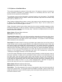
SWIM
(Soil and Water Integrated Model)
User Manual
Valentina Krysanova, Frank Wechsung
Potsdam Institute for Climate Impact Research, Potsdam, Germany
in collaboration with
Jeff Arnold, Ragavan Srinivasan and Jimmy Williams
USDA ARS, Temple, TX, USA
Version: SWIM-8
December 2000
-2-
Abstract
Development of integrated tools for hydrological/vegetation/water quality modelling at the
river basin scale is motivated by water resources management in densely populated
agricultural areas (water pollution problem), arid and semi-arid regions (water scarcity), and
mountainous and loess regions (erosion problem). The other motivation is an ongoing
climate change and land use/land cover change. Development of water resources in the
conditions of global change requires an understanding and adequate representation in
models of basic hydrologic and related processes at mesoscale and large scale, i.e. in river
basins of hundreds, thousands or tens of thousands of square kilometers.
The model SWIM (Soil and Water Integrated Model) was developed in order to provide a
comprehensive GIS-based tool for hydrological and water quality modelling in mesoscale
2
and large river basins (from 100 to 10,000 km ), which can be parameterised using
regionally available information. The model was developed for the use mainly in Europe
and temperate zone, though its application in other regions is possible as well. SWIM is
based on two previously developed tools - SWAT and MATSALU (see more explanations in
section 1.1).
The model integrates hydrology, vegetation, erosion, and nutrient dynamics at the
watershed scale. SWIM has a three-level disaggregation scheme ‘basin – sub-basins –
hydrotopes’ and is coupled to the Geographic Information System GRASS (GRASS, 1993).
A robust approach is suggested for the nitrogen and phosphorus modelling in mesoscale
watersheds. SWIM runs under the UNIX environment.
Model test and validation were performed sequentially for hydrology, crop growth, nitrogen
and erosion in a number of mesoscale watersheds in the German part of the Elbe drainage
basin. A comprehensive scheme of spatial disaggregation into sub-basins and hydrotopes
combined with reasonable restriction on a sub-basin area allows performing the
assessment of water resources and water quality with SWIM in mesoscale river basins. The
modest data requirements represent an important advantage of the model. Direct
connection to land use and climate data provides a possibility to use the model for analysis
of climate change and land use change impacts on hydrology, agricultural production, and
water quality.
However, the model is quite complicated, and it cannot be used as a black box.
Understanding of the model code is a prerequisite for successful applications.
-3-
-4-
CONTENTS
1. MODEL DESCRIPTION.............................................................................................
1.1 MODEL HISTORY.......................................................................................
1.2 GENERAL DESCRIPTION...........................................................................
1.2.1 Model objectives...........................................................................
1.2.2 Processes described in the model................................................
1.2.3 Spatial disaggregation..................................................................
1.2.4 GIS Interface................................................................................
1.2.5 Modelling procedure.....................................................................
1.3 OVERVIEW OF THE SWIM/GRASS INTERFACE.......................................
1.3.1 Main menu...................................................................................
1.3.2 Options of the main menu.............................................................
1.4 OVERVIEW OF THE MODEL COMPONENTS............................................
1.4.1 Hydrological processes.................................................................
1.4.2 Crop / vegetation growth...............................................................
1.4.3 Nutrient dynamics.........................................................................
1.4.4 Erosion.........................................................................................
1.4.5 River routing.................................................................................
2. MATHEMATICAL DESCRIPTION OF THE MODEL COMPONENTS........................
2.1 HYDROLOGICAL PROCESSES..................................................................
2.1.1 Snow melt....................................................................................
2.1.2 Surface runoff...............................................................................
2.1.3 Peak runoff rate............................................................................
2.1.4 Percolation...................................................................................
2.1.5 Lateral subsurface runoff..............................................................
2.1.6 Potential evapotranspiration.........................................................
2.1.7 Soil evaporation and plant transpiration........................................
2.1.8 Groundwater flow.........................................................................
2.1.9 Transmission losses.....................................................................
2.2 CROP / VEGETATION GROWTH................................................................
2.2.1 Crop growth..................................................................................
2.2.2 Growth constraint: water stress....................................................
2.2.3 Growth constraint: temperature stress..........................................
2.2.4 Growth constraints: nutrient stress...............................................
2.2.5 Crop yield and residue..................................................................
2.2.6 Adjustment of net photosynthesis to altered CO2..........................
2.2.7 Adjustment of evapotranspiration to altered CO2...........................
2.3 NUTRIENT DYNAMICS...............................................................................
2.3.1 Soil temperature...........................................................................
2.3.2 Fertilisation and input with precipitation.........................................
2.3.3 Nitrogen mineralisation.................................................................
2.3.4 Phosphorus mineralisation............................................................
2.3.5 Phosphorus sorbtion/adsorption...................................................
2.3.6 Denitrification................................................................................
2.3.7 Nutrient uptake by crops...............................................................
2.3.8 Nitrate loss in surface runoff and leaching to groundwater............
2.3.9 Soluble phosphorus loss in surface runoff.....................................
2.4 EROSION....................................................................................................
2.4.1 Sediment yield..............................................................................
2.4.2 Organic nitrogen transport by sediment........................................
2.4.3 Phosphorus transport by sediment...............................................
2.5 RIVER ROUTING........................................................................................
2.5.1 Flow routing.................................................................................
2.5.2 Sediment routing..........................................................................
2.5.3 Nutrient routing.............................................................................
-5-
11
12
16
16
16
20
20
22
23
23
24
28
28
29
30
31
31
33
34
34
34
40
43
45
46
49
51
53
55
55
58
59
60
61
65
69
71
71
74
74
77
78
78
79
81
83
86
86
88
89
90
90
92
94
Table 2.1 Abbreviations.....................................................................................
3. SWIM CODE STRUCTURE AND INPUT PARAMETERS..........................................
3.1 STRUCTURE of the SWIM/GRASS INTERFACE........................................
3.2 STRUCTURE of the SWIM SIMULATION PART..........................................
3.2.1 Files and their functions................................................................
3.2.2 Subroutines and their functions.....................................................
3.2.3 Main administrative subroutines and the parameter read part......
3.3 INPUT AND OUTPUT FILES.......................................................................
3.4 INPUT PARAMETERS.................................................................................
3.4.1 Input file .cod................................................................................
3.4.2 Input file .fig..................................................................................
3.4.3 Input file .bsn................................................................................
3.4.4 Input file .str..................................................................................
3.4.5 Input file sub-prst.dat....................................................................
3.4.6 Input file crop.dat..........................................................................
3.4.7 Input file wgen.dat........................................................................
3.4.8 Input file .sub................................................................................
3.4.9 Input file .gw.................................................................................
3.4.10 Input file .rte...............................................................................
3.4.11 Input file wstor.dat......................................................................
3.4.12 Input file soilNN.dat.....................................................................
3.4.13 Block data in the file init.f............................................................
4. HOW TO PREPARE INPUT DATA AND RUN SWIM.................................................
4.1 SPATIAL DATA PREPARATION.................................................................
4.1.1 GIS data overview........................................................................
4.1.2 How to choose the spatial resolution?...........................................
4.1.3 How to choose the average sub-basin area?................................
4.1.4 GRASS GIS overview...................................................................
4.1.5 Useful GRASS programs and functions........................................
4.1.6 Map export from ARC/INFO to ASCII format................................
4.1.7 Watershed analysis program r.watershed.....................................
4.1.8 DEMO data set.............................................................................
4.2 SWIM/GRASS INTERFACE........................................................................
4.3 RELATIONAL DATA PREPARATION..........................................................
4.3.1.The overview of relational data.....................................................
4.3.2 Climate data.................................................................................
4.3.3 Soil data.......................................................................................
4.3.4 Crop parameters and crop management data..............................
4.3.5 Hydrological and water quality data..............................................
4.4 MODEL RUN...............................................................................................
4.4.1 Collect all input data.....................................................................
4.4.2 Modification of the code to adjust for specific input data...............
4.4.3 Sensitivity analysis........................................................................
4.4.4 Overview of the model applications...............................................
APPENDIX I GRASS commands useful for the spatial data preparation for SWIM.........
REFERENCES................................................................................................................
ACKNOWLEDGEMENTS...............................................................................................
.
-6-
95
105
106
113
113
118
122
127
133
133
136
137
140
141
141
148
149
152
153
155
156
159
161
162
162
166
166
167
168
170
174
176
183
188
188
188
191
196
196
197
197
199
200
224
227
235
239
LIST OF TABLES
Chapter 1
Page
Tab. 1.1
Comparison of advantages and disadvantages of SWAT and MATSALU........ 15
Chapter 2
Tab. 2.1
Abbreviations to equations 1 – 194................................................................
Chapter 3
95
Tab. 3.1
Tab. 3.2
Tab. 3.3
Tab. 3.4
Tab. 3.5
Tab. 3.6
Tab. 3.7
Tab. 3.8
Tab. 3.9
Description of files included in SWIM/GRASS interface...................................
File swimmake used to compile SWIM/GRASS interface.................................
Files and subroutines included in SWIM code..................................................
File Makefile used to compile SWIM code.......................................................
Description of subroutines included in SWIM simulation part...........................
Structure of the subroutine MAIN....................................................................
Structure of the subroutine SUBBASIN............................................................
Structure of the subroutine HYDROTOP.........................................................
Structure of the subroutines OPEN, READCOD, READBAS, READCRP,
READSUB, READSOL, READWET.................................................................
Input files.........................................................................................................
Output files......................................................................................................
Baseflow factor bff...........................................................................................
Crop data base (file crop.dat)..........................................................................
Crop abbreviated names, full names and the corresponding land cover
categories......................................................................................................
Values of Manning’s “n” for overland flow.........................................................
Water erosion control practice factor P and slope-length limits for contouring..
Values of Manning’s “n” for channels...............................................................
Effective hydraulic conductivity of the channel alluvium...................................
Mean physical properties of soils ....................................................................
Curve Numbers for land use categories and four soil groups used in SWIM....
SCS Curve Numbers for a variety of land use/land cover categories...............
Chapter 4
108
112
114
117
118
123
124
125
Tab. 3.10
Tab. 3.11
Tab. 3.12
Tab. 3.13
Tab. 3.14
Tab. 3.15
Tab. 3.16
Tab. 3.17
Tab. 3.18
Tab. 3.19
Tab. 3.20
Tab. 3.21
Tab. 4.1
Tab. 4.2
Tab. 4.3
Tab. 4.4
Tab. 4.5
Tab. 4.6
Tab. 4.7
Tab. 4.8
Tab. 4.9
Tab. 4.10
Tab. 4.11
Tab. 4.12
Tab. 4.13
Tab. 4.14
Tab. 4.15
Tab. 4.16
Recommended resolution of DEM for some typical applications......................
List of source ASCII files and the corresponding maps in GRASS...................
Maps created with r.watershed using different thresholds................................
Comparison of three sub-basin maps created with different thresholds............
GRASS report about the soil map soil3, indicating areal distribution of soil
types..............................................................................................................
GRASS report about sub-basin map bas3 and the map of Thiessen polygons
for precipitation stations...................................................................................
Keystroke guide for using the interface............................................................
Format of temperature data.............................................................................
Format of precipitation data.............................................................................
Format of radiation data..................................................................................
Format of monthly statistics for climate stations...............................................
Format of soil parameters for SWIM................................................................
Estimation of saturated conductivity based on soil texture class and bulk
density (based on Bodenkundliche Kartieranleitung, 3.)...................................
Estimation of saturated conductivity based on soil texture class and bulk
density (based on Bodenkundliche Kartieranleitung, 4.)...................................
Format of water discharge data for SWIM.......................................................
Results of sensitivity analysis for the Stepenitz basin......................................
-7-
126
128
130
138
142
144
151
152
154
155
158
159
160
166
177
177
179
180
182
183
189
189
189
190
191
194
195
196
203
LIST OF FIGURES
Chapter 1
Fig. 1.1
Fig. 1.2
Fig. 1.3
Fig. 1.4
Fig. 1.5
Fig. 2.1
Fig. 2.2
Fig. 2.3
Fig. 2.4
Fig. 2.5
Fig. 2.6
Fig. 2.7
Fig. 2.8
Fig. 2.9
Fig. 2.10
Fig. 2.11
Fig. 2.12
Fig. 2.13
Fig. 2.14
Fig. 2.15
Fig. 2.16
Fig. 2.17
Fig. 2.18
Fig. 2.19
Fig. 2.20
Fig. 2.21
Fig. 2.22
Fig. 2.23
Model development based on the CREAMS model.........................................
Flow chart of the SWIM model, integrating hydrological processes,
crop/vegetation growth, and nutrient dynamics...............................................
Flow chart of hydrological processes in soil as implemented in SWIM.............
Nitrogen and phosphorus flow charts as implemented in SWIM......................
Three level disaggregation scheme ‘basin – sub-basins – hydrotopes’
implemented in SWIM.....................................................................................
Chapter 2
Estimation of surface runoff, Q, from daily precipitation, PRECIP, for different
values of CN (equations 3 and 4)....................................................................
Correspondence between CN1, CN2 and CN3 (equations 6, 7).........................
Adjustment of curve number CN2 to the slope (equation 8) for some typical
values of CN2 = 67, 78, 85, and 89, corresponding to straight row crop and
four hydrologic groups A, B, C, and D, respectively.........................................
Retention coefficient SMX and curve number CN as functions of soil water
-1
content SW (equation 9 and 4) assuming CN2 = 60, WP = 5 mm mm , FC =
-1
-1
35 mm mm , PO = 45 mm mm ......................................................................
Hydraulic conductivity as a function of soil water content (equation 39)
-1
-1
-1
assuming SC = 50.8 mm h , FC = 33 mm mm , UL = 43 mm mm .................
An example of the annual dynamics of soil albedo (equations 58, 59).............
Potential soil evaporation, ESO, as a function of leaf area index, LAI
-1
(equation 61) under assumption that EO = 6 mm d ........................................
Photosynthetic active radiation, PAR as a function of leaf area index, LAI for
RAD= 1000, 2000 and 3000 Ly (equation 83).................................................
Leaf area index as a function of the heat unit index (equation 87)...................
Temperature stress factor as a function of average daily air temperature
(equations 96 and 98), assuming TO = 25° C and TB = 3° C..........................
Nitrogen stress factor as a function of N supply and N demand (equations
100 – 101).....................................................................................................
Harvest index as a function of heat unit index (factor HIC1, equation 103).....
Harvest index as a function of soil water content (factor HIC2, equation 104)...
Scheme of operations included in SWIM crop module....................................
Factor ALFA as a function of CO2 concentration for wheat and maize
estimated using the first method (equations 108, 109, 110) and assuming BE
2
-1
-1
-1
2
-1
-1
-1
= 30 kg m MJ ha d for wheat and BE = 40 kg m MJ ha d for maize.
The CO2 concentration is changing from 330 to 660 ppm................................
ALFA factor for cotton, wheat and maize as dependent on temperature in the
case of CO2 doubling (a) and in the case of 50% increase in CO2 (b)
assuming initial CO2 concentration 330 ppm (equations 111 - 115 and 121)...
Comparison of two methods for the estimation of ALFA and BETA factors:
ALFA and BETA as functions of CO2 concentration under assumption that
temperature is 17° C for the second method...................................................
An example of soil temperature dynamics in five soil layers simulated with
SWIM using equation 131...............................................................................
Temperature factor of mineralisation, TFM (equation 142)..............................
Soil water factor of denitrification (equation 151).............................................
The optimal crop N concentration, CNB, as a function of growth stage IHUN
-1
-1
(equation 154) assuming BN1 = 0.06 g g , BN2 = 0.0231 g g and BN3 =
-1
0.0134 g g ............................................................................
Coefficient CW to calculate the amount NO3-N lost from the layer as a
function of water content (equation 160).........................................................
Scheme of operations included in SWIM nitrogen module...............................
-8-
Page
13
17
18
19
21
35
36
37
38
44
49
50
56
57
60
61
62
63
64
66
68
70
73
76
79
80
82
84
Fig. 2.24
Fig. 2.25
Fig. 2.26
Fig. 2.27
Scheme of operations included in SWIM phosphorus module.........................
The LS factor calculated as a function of slope steepness SS for different
slope lengths SL (equations 166-167).............................................................
Coefficients C1, C2 and C3 as functions of parameter KST as used to calculate
flow routing with the Muskingum equations 182-184 assuming that X = 0.2
and ∆t = 1......................................................................................................
spexp
Function SPCON⋅CHV
to estimate the sediment delivery ratio DELR
(equation 191) for different combinations of (CHV, SPCON)...........................
Chapter 3
85
87
91
94
Fig. 3.1
Fig. 3.2
Function tree of SWIM/GRASS interface........................................................ 107
Scheme of operations in the simulation part of SWIM..................................... 116
Chapter 4
Fig. 4.1
Fig. 4.15
A set of four maps: Digital Elevation Model (a), land use (b), soil (c), and
sub-basins (d) that are necessary to run SWIM/GRASS interface...................
Comparison of a virtual river networks produced by GRASS (blue) and a
digitazed river network (red)............................................................................
Virtual sub-basins obtained by applying r.watershed function in GRASS for
the Mulde river basin......................................................................................
A set of sub-basin and river network maps produced with r. watershed using
different thresholds: 900 (a), 200 (b) and 50 (c)..............................................
An overlay of the sub-basin map, the precipitation station map and the
Thiessen polygon map for the Glonn basin (a, b)............................................
Estimation of saturated conductivity using three different methods for
dominant soils in the Glonn basin...................................................................
Sensitivity to the method of estimation of saturated conductivity.....................
Sensitivity to saturated conductivity (sc read)..................................................
Sensitivity to saturated conductivity (sc calculated).........................................
Sensitivity to soil depth...................................................................................
Sensitivity to the soil group assignment..........................................................
Sensitivity to the Curve Number method: CN different in comparison to
CN= 30, 70.....................................................................................................
Sensitivity to the Curve Number method: CN different in comparison to
CN= 50, 90.....................................................................................................
Sensitivity to the Curve Number method: CN different in comparison to
CN = 50, 80....................................................................................................
Sensitivity to the baseflow factor (bff = 1; 0.5; 0.2)..........................................
Fig. 4.16
Fig. 4.17
Fig. 4.18
Fig. 4.19
Fig. 4.20
Fig. 4.21
Fig. 4.22
Fig. 4.23
Fig. 4.24
Sensitivity to the baseflow factor (bff = 1; 1.5; 3.)............................................
Sensitivity to the alpha factor for groundwater (abf0 = .048, .024, .012)..........
Sensitivity to the alpha factor for groundwater (abf0 = .048, 0.1, 0.3)..............
Sensitivity to initial groundwater contribution to flow........................................
Sensitivity to initial water storage....................................................................
Sensitivity to the routing coefficients...............................................................
Sensitivity to the routing coefficients...............................................................
Sensitivity to the crop type: winter rye and maize............................................
Sensitivity to the crop type: winter rye and winter wheat.................................
Fig. 4.2
Fig. 4.3
Fig. 4.4
Fig. 4.5
Fig. 4.6
Fig. 4.7
Fig. 4.8
Fig. 4.9
Fig. 4.10
Fig. 4.11
Fig. 4.12
Fig. 4.13
Fig. 4.14
-9-
163
165
175
178
181
193
206
207
208
209
210
211
212
213
214
215
216
217
218
219
220
221
222
223
- 10 -
1. Model Description
This chapter includes an overview about the model history (section 1.1), the general
description of the model objectives, processes, and the spatial disaggregation (section 1.2),
a short overview of the model components (section 1.3), and a detailed mathematical
description of the model components (section 1.4).
- 11 -
1.1 Model History
The SWIM model is based on two previously developed tools – SWAT (Arnold et al., 1993
& 1994), and MATSALU (Krysanova et al., 1989a & b).
SWAT is a continuous-time distributed simulation watershed model. It was developed to
predict the effects of alternative management decisions on water, sediment, and chemical
yields with reasonable accuracy for ungauged rural basins. One of its attractive features is
that there is a long period of modeling experience behind this model (see Fig. 1.1).
In the mid-1970's in response to the Clean Water Act, the USDA Agricultural Research
Service (ARS) assembled a team of interdisciplinary scientists to develop a process-based,
nonpoint source simulation model. From that effort, a field scale model called CREAMS
(Chemicals, Runoff, and Erosion from Agricultural Management Systems) was developed
(Knisel, 1980) to simulate the impact of land management on water, sediment, and
nutrients.
In the 1980's, several models have been developed with origins from the CREAMS model.
One of them, the GLEAMS model (Groundwater Loading Effects on Agricultural
Management Systems) (Leonard et al., 1987) concentrated on pesticide and nutrient load
to groundwater. Another model called EPIC (Erosion-Productivity Impact Calculator)
(Williams et al., 1984 & 1985) was originally developed to simulate the impact of erosion on
crop productivity and has now evolved into a comprehensive agricultural field scale model
aimed in the assessment of agricultural management and nonpoint source loads. One more
model for estimating the effects of different management practices on nonpoint source
pollution from field-sized areas and also based on CREAMS is the OPUS model (Smith,
1992). These three models can be applied for the field-scale areas or small homogeneous
watersheds.
Other efforts involved modifying CREAMS to simulate complex watersheds with varying
soils, land use, and management, which resulted in the development of several models, like
AGNPS (Young et al., 1989), SWRRB (Arnold et al., 1990) and MATSALU (Krysanova et
al., 1989a & b).
AGNPS (AGricultural NonPoint Source) is a spatially detailed, single event (storm) model
that subdivides complex watersheds into grid cells.
- 12 -
GLEAMS
EPIC
ROTO
GRASS Interface
AGNPS
CREAMS
SWRRB
SWAT
MATSALU
SWIM
OPUS
Fig. 1.1Model development based on the CREAMS model
SWRRB (Simulator for Water Resources in Rural Basins) was developed to simulate
nonpoint source pollution from watersheds. It is a continuous time (daily time step) model
that allows a basin to be subdivided into a maximum of ten sub-basins. To create SWRBB,
the CREAMS model was modified for application to large, complex, rural basins.
The major changes involved were the following
• the model was expanded to allow simultaneous computations on several sub-basins;
• a better method was developed for predicting the peak runoff rate;
• a lateral subsurface flow component was added;
• a crop growth model was appended to account for annual variation in growth and its
influence on hydrological processes;
• a pond/reservoir storage component was adjoined;
• a weather generator (rainfall, solar radiation, and temperature) was added for more
representative weather inputs, both temporally and spatially;
• a module accounting for transmission losses was appended;
• a simple flood routing component was adjoined; and
• a sediment routing component was added to simulate sediment movement through
ponds, reservoirs, streams, and valleys.
SWRRB was still limited to ten sub-basins and had a simplistic routing structure with
outputs routed from the sub-basin outlets directly to the basin outlet. This problem led to
the development of a model called ROTO (Routing Outputs to Outlet) (Arnold et al., 1990),
which took outputs from SWRRB run on multiple sub-basins and routed the flows through
channels and reservoirs. ROTO provided a reach routing approach and overcame the
SWRRB sub-basin limitation by "linking" the sub-basin outputs.
Although the combination SWRRB + ROTO was quite effective, especially in comparison
with CREAMS, the input and output of multiple files was cumbersome and required
considerable computer storage. Limitations also occurred due to the fact that all SWRRB
runs had to be made independently, and then the SWRRB outputs had to be input to
ROTO for the channel and reservoir routing. Finally, the model called SWAT (Soil and
Water Assessment Tool) was developed merging SWRRB and ROTO into one basin scale
model. SWAT is a continuous time model working with daily time step, which allows a basin
to be divided into hundreds or thousands of sub-watersheds or grid cells.
One more model, MATSALU, was developed in Estonia for the agricultural basin of the
2
Matsalu Bay (which belongs to the Baltic Sea) with the area about 3,500 km and the bay
ecosystem in order to evaluate different management scenarios for the eutrophication
control of the Bay. The model consists of four coupled submodels, which simulate 1)
watershed hydrology, 2) watershed geochemistry, 3) river transport of water and nutrients,
and 4) nutrient dynamics in the Bay ecosystem. Similar to SWRRB, its watershed
components were essentially based on the CREAMS approach.
Spatial disaggregation in MATSALU is based on the overlay of three map layers: a map of
2
elementary watersheds with an average area of 10 km , a land use map, and a soil map, to
obtain so-called Elementary Areas of Pollution (EAP). Conceptually the EAPs are similar to
Hydrologic Response Units (HRU) or hydrotopes. The three-level disaggregation scheme of
MATSALU includes ‘the basin – elementary sub-basins – EAPs’. Since the model was
developed for the MATSALU watershed and connected to specific data sets, it is not
sufficiently transferable.
- 14 -
Merging the two tools: SWAT and MATSALU, we tried to keep their best features and
maintain their advantages (see Tab. 1.1). The model code was mostly based on SWAT.
The more comprehensive three-level spatial disaggregation scheme from MATSALU was
introduced into SWAT as an initial step. The next step was to adjust the model for the use
in European conditions, where data availability is different. This required some efforts in
order to modify the data input. Besides, several modules were excluded from SWAT
(pesticides, ponds/reservoirs, lake water quality) in order to avoid the overparametrization.
Table 1.1Comparison of advantages and disadvantages of SWAT and MATSALU
SWAT
Advantages
Disadvantages
•
Coupling with GIS
•
Two-level disaggregation (basin and
sub-basins) in SWAT-93
•
Hydrological module tested
in several meso- and
macroscale watersheds
•
Connection to specific American
data sets (especially soil, climate)
•
SWAT as a long-term predictor was
always tested and validated only
with monthly time step
•
Connection to specific Estonian data
sets, not transferable to other basins
•
Four coupled models, not a coupled
watershed model
•
MATSALU
•
•
Vegetation module
(simplified EPIC) is adopted
for different crops and
natural vegetation
Three-level disaggregation
scheme
N-module was tested in
mesoscale watershed in
connection with hydrology
and river transport
In parallel to the model development, its modules were sequentially tested in the Elbe
basin, starting from hydrology. In contrast to SWAT, the hydrological module of SWIM has
been validated with a daily time step. During the test, some subroutines were modified,
some parameters were changed, and some components have been substituted.
Currently the model SWIM includes some common (or similar) modules of both
predecessors and some new routines, like the flow routing, which is based on Muskingum
method instead of ROTO in SWAT and Sant-Venant approach in MATSALU. The
SWAT/GRASS interface was modified for SWIM.
Further development of the model is planned in the following directions:
• standardization of climate and crop management input data,
• addition of a module accounting for the carbon cycle in soil;
• addition of the lake and watershed modules;
• improving the description of lateral transport of nutrients; and
• modifying SWIM/GRASS interface to include automatic
climate/precipitation stations to sub-basins.
- 15 -
connection
of
1.2 General Description
1.2.1 Model Objectives
The objectives of the model are two-fold:
• to provide a comprehensive GIS-based tool for the coupled hydrological/
vegetation/water quality modelling in mesoscale watersheds (from 100 up to 10,000
2
km ), which can be parameterised using regionally available data, and
• to enable the use of the model for analysis of climate change and land use change
impacts on hydrological processes, agricultural production and water quality at the
regional scale.
1.2.2 Processes Described in the Model
SWIM integrates hydrology, erosion, vegetation, and nitrogen/phosphorus dynamics at the
river basin scale (Fig. 1.2) and uses climate input data and agricultural management data
as external forcing. The hydrological module is based on the water balance equation,
taking into account precipitation, evapotranspiration, percolation, surface runoff, and
subsurface runoff for the soil column subdivided into several layers.
The simulated hydrological system consists of four control volumes: the soil surface, the
root zone, the shallow aquifer, and the deep aquifer (Fig. 1.3). The percolation from the soil
profile is assumed to recharge the shallow aquifer. Return flow from the shallow aquifer
contributes to the streamflow. The soil column is subdivided into several layers in
accordance with the soil data base. The water balance for the soil column includes
precipitation, evapotranspiration, percolation, surface runoff, and subsurface runoff. The
water balance for the shallow aquifer includes ground water recharge, capillary rise to the
soil profile, lateral flow, and percolation to the deep aquifer.
The nitrogen module includes the following pools (Fig. 1.4): nitrate nitrogen (NO3-N), active
and stable organic nitrogen, organic nitrogen in the plant residue, and the flows:
fertilisation, input with precipitation, mineralisation, denitrification, plant uptake, wash-off
with surface and subsurface flows, leaching to ground water, and loss with erosion. The
phosphorus module includes the pools: labile phosphorus, active and stable mineral
phosphorus, organic phosphorus, and phosphorus in the plant residue, and the flows:
fertilisation, sorption/desorption, mineralisation, plant uptake, loss with erosion, wash-off
with lateral flow. The wash-off to surface water and leaching to groundwater are more
important for nitrogen, while phosphorus is mainly transported with erosion.
The module representing crop and natural vegetation is an important interface between
hydrology and nutrients. The same as in SWAT, a simplified EPIC approach (Williams et
al., 1984) is included in SWIM for simulating all arable crops considered (wheat, barley,
corn, potatoes, alfalfa, and others), using unique parameter values for each crop, which
were obtained in different field studies. Simplification relates mainly to less detailed
description of phenological processes and lower requirements on the input information.
This enables to simulate crop growth in a distributed modelling framework for quite large
basins and regions. Non-arable and natural vegetation is included in the database through
some ‘aggregated’ vegetation types like ‘grass’, ‘pasture’, ‘forest’, etc. and can be simulated
as well.
- 16 -
Climate: solar radiation, temperature, & precipitation
Nitrogen cycle
Hydrological cycle
Crop/vegetation
growth
A
B
LAI
C
Biomass
Shallow
groundwater
Roots
Nm
Noac
Nost
Nres
Phosphorus cycle
Plab
Pmac
Pmst
Porg
Pres
Deep
groundwater
Land use pattern & land management
Fig. 1.2
Flow chart of the SWIM model, integrating hydrological processes, crop/vegetation growth, and nutrient dynamics
Fig. 1.3 Flow chart of hydrological processes in soil as implemented in SWIM
- 18 -
Fig. 1.4 Nitrogen and phosphorus flow charts as implemented in SWIM
- 19 -
1.2.3 Spatial Disaggregation
A three-level disaggregation scheme similar to that used in MATSALU is implemented in
SWIM for mesoscale basins (Fig. 1.5). The three-level disaggregation scheme in SWIM
implies 1) basin, 2) sub-basins, and 3) hydrotopes inside sub-basins. The idea is that a
2
mesoscale basin (from 100 to 10,000 km ) is first subdivided into sub-basins of reasonable
average area (see explanation in section 3.1.3). This can be done
using the r.watershed program of GRASS (or any other GIS with similar capabilities), which
is applied to a Digital Elevation Model of the area with a certain threshold for the average
size of the sub-basin.
After that the hydrotopes (or HRUs) are delineated within every sub-basin, based on land
use and soil types. Normally, a hydrotope is a set of disconnected units in the sub-basin,
which have a unique land use and soil type. A hydrotope can be assumed to behave in a
hydrologically uniform way within the sub-basin.
1.2.4 GIS Interface
The SWAT/GRASS interface (Srinivasan, Arnold, 1993; Srinivasan et al., 1993) was
adopted and modified for SWIM to extract spatially distributed parameters of elevation, land
use, soil types, and groundwater table. The interface creates a number of input files for the
basin and sub-basins, including the hydrotope structure file (indicating sub-basin number,
land use and soil type for every hydrotope) and the routing structure file (indicating how the
sub-basins are connected via river network). To start the interface, the user must have at
least four map layers of a basin. Three of them are the elevation map, the land use map,
and the soil map. The fourth, sub-basin map, should be created in advance either using the
r.watershed program of GRASS or by subdividing the basin in any other way.
Step 1. Sub-basin attributes This is the first step to be fulfilled. The program calculates
area, resolution, and co-ordinate boundaries for the basin and each sub-basin, using a
given sub-basin map. Further, the fraction of each sub-basin area to the basin area is
calculated.
Step 2. Topographic attributes The program estimates the stream length, stream slope
and geometrical dimensions using the r.stream.att tool (Srinivasan, Arnold, 1994). The
cross sectional dimensions (width and depth) of a stream are estimated using a neural
network that is embedded in the interface, based on the drainage area and average
elevation of a sub-basin (which should be “trained” on the regional data before use). The
accumulation area and aspect are computed using the standard methods in GRASS. The
weighted average method is used to estimate the overland slope and slope length. Finally,
the channel USLE (Universal Soil Loss Equation) factors K and C are estimated using a
standard table.
Step 3. Hydrotope structure The program defines the basin hydrotope structure by
overlaying the sub-basin map with land use and soil layers. The structure file is created to
run the model. Each line in the file describes the characteristics of one hydrotope - its subbasin number, land use, and soil.
Step 4. Weather attributes The program selects the closest weather/precipitation station
to every sub-basin. Then either actual weather information can be used, or the weather
generator (in this case the long-term monthly statistical parameters must be available for
precipitation and temperature for the station). This part of the interface has to be modified
to provide more flexible input of climate information.
- 20 -
basin
river routing
(water, N, P, sediments)
Fig 1.5
sub-basins
aggregation of
lateral flows
Three level disaggregation scheme ’basin - sub-basins – hydrotopes‘ implemented in SWIM
hydrotopes
water, N, P cycling,
vegetation growth
Step 5. Ground water attributes The ground water parameters are estimated for each
sub-basin using the alpha layer (the reaction factor described in 2.2). This parameter
defines the time lag needed to the groundwater flow as it leaves the shallow aquifer to
reach the stream.
Step 6. Routing structure The interface creates the routing structure for the basin based
on the elevation map. The routing structure is put in a special file, which provides the
information about when to add flows and route through sub-basins and when to add inflow
(or subtract withdrawals) from any sub-basins.
Steps 1, 2, 5, 6 described above are the same as in the SWAT/GRASS interface, steps 3
and 4 are new, and some other steps from SWAT/GRASS (such as irrigation and nutrient
attributes) were excluded.
1.2.5 Modelling Procedure
First, the SWIM/GRASS interface runs to produce necessary input files. After that the
model itself can be run. The model operates on a daily time step. After the input
parameters are read from files, the three-step modelling procedure is applied. First, water
and nitrogen dynamics and crop/vegetation growth are calculated for every hydrotope.
Then the outputs from the hydrotopes, especially the lateral water and nutrient flows, are
averaged (area-weighted average) to estimate the sub-basin output. Finally, the routing
procedure is applied to the sub-basin outputs, taking transmission losses into account.
- 22 -
1.3 Overview of the SWIM/GRASS Interface
1.3.1 Main Menu
A menu-driven interface from GRASS to SWIM integrates SWIM with GRASS by preparing
a set of input files required to run a SWIM simulation. The interface provides a menu of
steps to prepare the input files. Each simulation is treated as "a project" by SWIM/INPUT,
which has a name (analogously to the GRASS project name). The inputs collected for the
steps are recorded under the project name, so that they may be copied or recalled for
further completion or modification.
The first menu displayed when running SWIM/INPUT includes functions:
• to create a new project,
• to work on existing projects,
• to copy an existing project, and
• to remove existing projects.
The user has to set the current GRASS mapset where the SWIM/GRASS project will be
created, otherwise an error message or erroneous results will occur. The main menu
includes steps to be completed to prepare input files for SWIM, plus some other
miscellaneous functions as following:
SWIM / GRASS Project Data Extraction Menu
Project Name: Dahme <example>
run
run
run
run
run
run
run
0
1
2
3
4
5
6
7
8
9
Choose desired option:
Quit
Extract data from layers
Display Raster, Vector and/or Site Maps
Extract Basin Attributes
Extract Hydrotope Structure
Extract Topographic Attributes
Extract Groundwater Attributes
Compute Routing Structure and Create .fig file
Extract Climate Station
Extract Precipitation Station
Option: 0__
AFTER COMPLETING ALL ANSWERS, HIT <ESC> TO CONTINUE
(OR <Ctrl-C> TO EXIT)
Steps 3-9 record and display their status to the left of the step number. If a step has not
been run, "run" status is displayed (as seen above). If the step has been successfully
completed, the status will be listed as "done". In some cases, a change in one step will
cause the need to run another step again, in which case the status will read "rerun". If a
step having the status of "done" or "rerun" is run again, it will attempt to offer previous
inputs as defaults.
- 23 -
1.3.2 Options of the Main Menu
This section describes the options of the main menu. All steps are verbose to provide as
much immediate information as needed, however it is necessary that the user is also
familiar with the operations of SWIM itself.
The sub-basin map must be delineated in advance based on the topography. The GRASS
r.watershed command can be used to create the sub-basin map from an elevation map
layer (see e.g. Section 3.1.6).
Step 2 helps to display either a raster, vector or site maps over the sub-basin map and also
to display the sub-basin number on the graphical screen. Step 2 can be used only in
conjunction with the GRASS graphic monitor.
Steps 3 through 9 collect inputs (either maps from the currently available mapsets or other
text/numerical inputs) in order to create or extract the necessary portions of SWIM inputs
for that step. Step 3 should be the first step; step 7 should be completed before moving into
step 0 to leave the interface.
Menu Option 3: Extract Basin Attributes
Map Input: Sub-basin Map
Technical Description: This is the first step before attempting to extract any other input.
Using a given sub-basin map the program calculates area, resolution, and geographic coordinate boundaries for the basin and for each sub-basin. The fraction of each sub-basin
within the basin is also estimated.
Description: All raster values in the input sub-basin map greater than zero will be used to
create reclass rules to set the project MASK to the basin and sub-basin areas. Each time
the project is called, the MASK will be automatically set. The project resolution is extracted
from the sub-basin map in meters and used to set the cell size of the all other extraction of
data from other GIS layers. When the user runs the step 5 to extract topographic attributes,
and an ‘memory error’ message appears, then either the program has to be run with larger
memory or the resolution of the sub-basin map has to be increased by running the
r.resample to set bigger resolution of the sub-basin map.
A part of this step attempts to find the minimal region needed to contain the basin mask at
the given resolution. A region will be calculated to allow at least a one-cell border around
the basin area. After the project mask, region and resolution are set, the information is
recorded and will be reset automatically each time the project is called. If any of the inputs
in this step are subsequently reset, all other steps that may have been completed will be
marked with a status of "rerun" or "run", since changing basin, resolution or region will
require that inputs will have to be resampled and extracted once again.
Menu Option 4: Extract Hydrotope Structure
Map Input: Basin Map, Land Use Map, Soil Map
Description: This step prompts for the name of an elevation map, land use map and soil
map for the project basin. The program starts the GRASS command r.stats for these three
maps and stores the output in the file project_name.str except these data where one of the
first three numbers is zero.
- 24 -
Menu Option 5: Extract Topographic Attributes
Map Input: Elevation Map
Technical Description: The topographic features required for entire basin and for each
sub-basin are gathered using an elevation map. By masking the entire basin and each subbasin, the stream length, stream slope and stream dimensions are estimated using the
concept of r.stream.att tool (Srinivasan and Arnold, 1994) along with proper aggregation
methods. The accumulation (drainage) area is computed for each sub-basin along with the
drainage aspect of which sub-basin flows into which sub-basin.
This information is later used to automate the routing structures for the SWIM model. The
starting and ending nodes of the stream for the basin and each sub-basin are estimated.
Using the r.topo.att tool (Srinivasan and Arnold, 1994) overland slope and slope length are
estimated and aggregated by the weighted average or mode (dominant) method. The
channel USLE K, USLE C, Manning’s “n” and USLE P factors are estimated using a
standard table and the knowledge obtained in the topographic attributes extraction
processes.
Description: This step prompts for the name of an elevation map for the project basin. The
elevation map should be true elevations in meters. If not, the user must apply r.mapcalc to
convert to meters. Programs have been developed to process an elevation surface map
and create SWIM slope and aspect map for the basin and for each sub-basin. The channel
length, channel slope, channel dimensions, average overland slope and slope length are
the parameters that are required for SWIM are extracted in this step.
This is one of the time consuming process. If this process is not completed due to memory
allocation problems the user is advised to either run the interface with a higher memory
machine or increase the resolution of the basin map and resample the data and run
through all the steps. The elevation map can be "filtered" to remove "pits" and other
potential problems to SWIM modelling with the r.fill.dir (Srinivasan and Arnold, 1994)
program. The extracted topographic attributes are stored in files with .sub and .rte
extensions for each sub-basin.
Menu Option 6:Extract Groundwater Attributes
Input Map: Alpha Map for Groundwater
Technical Description: The groundwater parameters are created for each sub-basin
using the so-called alpha layer map. This parameter is required to lag the groundwater flow
as it leaves the shallow aquifer to return to the stream (Arnold et. al., 1993).
Description: The interface prompts for the availability of the alpha parameter map. If the
answer is ‘no’, the interface assumes a default values for all the groundwater parameters. If
there is a groundwater parameter alpha map, the category values should be in hundreds.
The other groundwater parameters such as initial groundwater height etc. are assumed to
be default values. A detailed description of the procedure to create the alpha map can be
found in Arnold et al., 1993.
Menu Option 7: Compute Routing Structure and Create .fig file
Input Data: Automatic
- 25 -
Technical Description: In this step the interface creates a <project name.fig> file, which is
the main engine for running the SWIM model. This file has the information about when to
add flows and route through sub-basins and when to route through reservoirs and add
inflow or subtract withdrawals from any sub-basins and/or reaches. This step is automated
using the elevation map. Altering either step numbers 3 or 5 will require running this step
again.
Also this step determines the channel width and depth of flow for routing. This is done
using neural network that is embedded in the interface, which has been trained on the
USGS (United States Geologic Survey) defined 2-digit Hydrologic Unit Areas (HUA).
Several hundreds of width and depth information were collected and used in training the
neural network by the 2-digit HUA. A detailed description about the neural network method
and the datasets used here can be obtained by sending an e-mail request to
[email protected] or
[email protected].
The neural network needs the drainage area and the average elevation of a sub-basin to
find its width and depth of channel.
Description: This is one of the tedious operation, by automating this operation through the
GIS interface the user potentially saves several man hours and days of creating the ".fig"
file. In addition updating this file is also easy while considering several hypothetical
scenarios such as impact of reservoirs or inflow or withdrawal of flows or change in
cropping and management information. The interface checks the outlet sub-basin of the
watershed, which has to be confirmed by the user. Since this is determined by the elevation
map, there could be errors due to the spatial accuracy and/or the resolution of the elevation
map.
On completion of this step the interface creates a file <project name.flow>, which has
routing information of each sub-basin to the outlet of the basin showing the path of the flow
through other sub-basins. The model allows having multiple outlets for a basin, hence if the
user accepts more than one outlet, then the interface will create several outlets for that
basin. In the event of an error in the routing structure, the interface enters into another
menu where in the user can either enter through keyboard or using graphical monitor
determines how the flow has to occur. Once the user is satisfied with the routing structure,
the interface prompts for the 2-digit HUA where the basin belongs. Hence, the user needs
to know this info before running this step.
Menu Option 8: Extract Climate Station
Input Data: Climate Station File (number and coordinates (UTM) of each station)
Climate Station Raster Map
Technical Description: This will extract the number of the three nearest climate stations
for the basin or each sub-basin using the program brb_main_stationno.c. The step requires
a climate station number file "name". The station numbers are stored in the file name.cstn
under full_path. It also creates a label file to mark the searched stations in the map on the
Grass graphics monitor and in map hardcopies. The label file name.clabel is stored in the
necessary path
.../grass/databases/project_name/mapset/paint/labels.
- 26 -
To mark one station with its number the input in a label file has to look as follows:
east:
north:
xoffset:
yoffset:
ref:
font:
color:
size:
background:
opaque:
4610296.500000
5806264.000000
lower center
standard
black
500
white
yes
text:46663
After that the function find_subb_stations() is called. This function prompts for an existing
raster map of climate stations. It extracts all climate stations in each sub-basin using the
grass program r.mapcalc (see description of find_subb_stations()).
Menu Option 9: Extract Precipitation Station
Input Data: Precipitation Station File (number and coordinates of each station)
Precipitation Station Raster Map
Technical Description: This will extract the number of the three nearest precipitation
stations for the basin or each sub-basin using program brb_main_stationno.c. The step
requires a precipitation station number file "name". The station numbers are stored in the
file name.pstn under full_path. It also creates a label file to mark the searched stations in
the map on Grass graphics monitor and in map hardcopies. The label file name.plabel is
stored in the necessary path
.../grass/databases/project_name/mapset/paint/labels.
After that function find_subb_stations() is called. This function prompts for an existing raster
map of precipitation stations. It extracts all precipitation stations in each sub-basin using the
grass program r.mapcalc (see description of find_subb_stations() ).
Once the steps are completed from 3 to 9, by choosing the option 0, the user leaves the
interface. At this time the interface also creates the file.cio file, which has the entire input
file names prepared by interface. At this junction, the user can run the SWIM model.
The steps 8 and 9 need further modification. Currently, they can be also omitted.
- 27 -
1.4 Overview of the Model Components
1.4.1 Hydrological Processes
Snow melt The snow melt component is similar to that of the CREAMS model (Knisel,
1980), according to a simple degree-day equation. Melted snow is then treated in the same
way as rainfall for further estimation of runoff and percolation.
Surface runoff The runoff volume is estimated using a modification of the SCS curve
number method (Arnold et al, 1990). Surface runoff is predicted as a nonlinear function of
precipitation and a retention coefficient. The latter depends on soil water content, land use,
soil type, and management. The curve number and the retention coefficient vary nonlinearly from dry conditions at wilting point to wet conditions at field capacity and approach
100 and 0 respectively at saturation. The modification essentially reduced the empirism of
the original curve number method. The reliability of the method has been proven by multiple
validation of SWAT and SWIM in mesoscale basins. Nevertheless, there is a possibility to
exclude the dependence of the retention coefficient on land use and soil, leaving the
dependence on soil water content only, and assuming the same interval for all types of land
use and soils.
Percolation The same storage routing technique as in SWAT is used to simulate water
flow through soil layers in the root zone. Downward flow occurs when field capacity of the
soil layer is exceeded, and as long as the layer below is not saturated. The flow rate is
governed by the saturated hydraulic conductivity of the soil layer. Once water percolates
below the root zone, it becomes groundwater. Since the one day time interval is relatively
large for soil water routing, the inflow is divided into 4 mm slugs in order to take into
account the flow rate’s dependence on soil water content. If the soil temperature in a layer
is below 0°C, no percolation occurs from that layer. The soil temperature is estimated for
each soil layer using the air temperature as a driver (Arnold et al., 1990).
Lateral subsurface flow Lateral subsurface flow is calculated simultaneously with
percolation. The kinematic storage model developed by Sloan et al. (1983) is used to
estimate the subsurface flow. The approach is based on the mass continuity equation in the
finite difference form with the entire soil profile as the control volume. To account for
multiple layers, the model is applied to each soil layer independently starting at the upper
layer to allow for percolation from one soil layer to the next and percolation from the bottom
soil layer past the soil profile (as recharge to the shallow aquifer).
Evapotranspiration Potential evapotranspiration is estimated using the Priestley-Taylor
method (1972) that requires solar radiation and air temperature as input. It is possible to
use the Penman-Monteith method (Monteith, 1965) instead if wind speed and relative air
humidity data can be provided in addition. The actual evapotranspiration is estimated
following the Ritchie (1972) concept, separately for soil and plants. Actual soil evaporation
is computed in two stages. It is equal to the potential soil evaporation predicted by means
of an exponential function of leaf area index (Richardson and Ritchie, 1973) until the
accumulated soil evaporation exceeds the upper limit of 6 mm. After that stage two begins.
The actual soil evaporation is reduced and estimated as a function of the number of days
since stage two began. Plant transpiration is simulated as a linear function of potential
evapotranspiration and leaf area index. When soil water is limited, plant transpiration is
reduced, taking into account the root depth.
- 28 -
Groundwater flow The groundwater model component is the same as in SWAT (see
Arnold et al., 1993). The percolation from the soil profile is assumed to recharge the
shallow aquifer. Return flow from the shallow aquifer contributes directly to the streamflow.
The equation for return flow was derived from Smedema and Rycroft (1983), assuming that
the variation in return flow is linearly related to the rate of change of the water table height.
In a finite difference form, the return flow is a nonlinear function of ground water recharge
and the reaction factor RF, the latter being a direct index of the intensity with which the
groundwater outflow responds to changes in recharge. The reaction factor can be
estimated for gaged sub-basins using the base flow recession curve.
1.4.2 Crop / Vegetation Growth
The crop model in SWIM and SWAT is a simplification of the EPIC crop model (Williams et
al., 1984). The SWIM model uses a concept of phenological crop development based on
daily accumulated heat units;
Monteith’s approach (1977) for potential biomass;
water, temperature, and nutrients stress factors; and
harvest index for partitioning grain yield.
However, the more detailed approach implemented in EPIC for the root growth and nutrient
cycling is not included in order to maintain a similar level of complexity of all submodels and
to keep control on the model performance.
A single model is used for simulating all the crops and natural vegetation included in the
crop database attached to the model. Annual crops grow from planting date to harvest date
or until the accumulated heat units reach the potential heat units for the crop. Perennial
crops maintain their root systems throughout the year, although the plants may become
dormant after frost.
Phenological development of the crop is based on daily heat unit accumulation.
Interception of photosynthetic active radiation is estimated with Beer’s law equation (Monsi
and Saeki, 1953) as a function of solar radiation and leaf area index. The potential increase
in biomass is the product of absorbed PAR and a specific plant parameter for converting
energy into biomass.
The potential biomass is adjusted daily if one of the four plant stress factors (water,
temperature, nitrogen, and phosphorus) is less than 1.0 using the product of a minimum
stress factor and the potential biomass. The water stress factor is defined as the ratio of
actual to potential plant transpiration. The temperature stress factor is computed as a
function of daily average temperature, optimal and base temperatures for plant growth. The
N and P stress factors are based on the ratio of accumulated N and P to the optimal
values.
The fraction of daily biomass growth partitioned to roots is estimated to range linearly
between two fractions specified for each vegetation type - 0.4 at emergence to 0.2 at
maturity. Root depth increases as a linear function of heat units and potential root depth.
Leaf area index is simulated as a nonlinear function of accumulated heat units and crop
development stages. Crop yield is estimated using the harvest index, which increases as a
nonlinear function of heat units from zero at planting to the optimal value at maturity. The
harvest index is affected by water stress in the second half of the growing period.
- 29 -
1.4.3 Nutrient Dynamics
Nitrogen mineralisation The nitrogen mineralisation model is a modification of the
PAPRAN mineralisation model (Seligman and van Keulen, 1981). Organic nitrogen
associated with humus is divided into two pools: active or readily mineralisable organic
nitrogen and stable organic nitrogen. The model considers two sources of mineralisation: a)
fresh organic nitrogen pool, associated with crop residue, and b) the active organic nitrogen
pool, associated with the soil humus. Organic N flow between the active and stable organic
nitrogen pools is governed by the equilibrium equation. Mineralisation of fresh organic
nitrogen is a function of the C:N ratio, C:P ratio, soil temperature, and soil water content.
The N mineralisation flow from residue is distributed between the mineral nitrogen (80%)
and active organic nitrogen (20%) pools. Mineralisation of the active organic nitrogen pool
depends on soil temperature and water content.
Phosphorus mineralization The phosphorus mineralisation model is structurally similar to
the nitrogen mineralisation model. To maintain phosphorus balance at the end of a day,
humus mineralisation is subtracted from the organic phosphorus pool and added to the
mineral phosphorus pool, and residue mineralisation is distributed between the organic
phosphorus pool (20%) and the labile phosphorus (80%).
Sorption / adsorption of phosphorus Mineral phosphorus is distributed between three
pools: labile phosphorus, active mineral phosphorus, and stabile mineral phosphorus.
Mineral phosphorus flow between the active and stable mineral pools is governed by the
equilibrium equation, assuming that the stable mineral pool is four times larger. Mineral
phosphorus flow between the active and labile mineral pools is governed by the equilibrium
equation as well, assuming equal distribution.
Denitrification Denitrification, as one of the microbial processes, is a function of
temperature and water content. The denitrification occurs only in the conditions of oxygen
deficit, which usually takes place when soil is wet. The denitrification rate is estimated as a
function of soil water content, soil temperature, organic matter, a coefficient of soil wetness,
and mineral nitrogen content. The soil water factor is an exponential function of soil
moisture with an increasing trend when soil becomes wet.
Crop uptake of nutrients Crop uptake of nitrogen and phosphorus is estimated using a
supply and demand approach. Six parameters are specified for every crop in the crop
database, which describe: BN1 and BP1 - normal fraction of nitrogen and phosphorus in
plant biomass excluding seed at emergence, BN2 and BP2 – at 0.5 maturity, and BN3 and
BP3 - at maturity. Then the optimal crop N and P concentrations are calculated as functions
of growth stage. The daily crop demand of nutrients is estimated as the product of biomass
growth and optimal concentration in the plants. Actual nitrogen and phosphorus uptake is
the minimum of supply and demand. The crop is allowed to take nutrients from any soil
layer that has roots. Uptake starts at the upper layer and proceeds downward until the daily
demand is met or until all nutrient content has been depleted.
Soluble nutrient loss in surface water and groundwater The amount of NO3-N and
soluble P in surface runoff is estimated considering the top soil layer only. Amounts of NO3N and soluble P in surface runoff, lateral subsurface flow and percolation are estimated as
the products of the volume of water and the average concentration. Retention factor is
taken into account through transmission losses. Because phosphorus is mostly associated
with the sediment phase, the soluble phosphorus loss is estimated as a function of surface
runoff and the concentration of labile phosphorus in the top soil layer.
- 30 -
1.4.4 Erosion
Sediment yield is calculated for each sub-basin with the Modified Universal Soil Loss
Equation (MUSLE, Williams and Berndt, 1977), almost the same as in SWAT. The equation
for sediment yield includes the runoff factor, the soil erodibility factor, the crop management
factor, the erosion control practice factor, and the slope length and steepness factor. The
only difference from SWAT is that the surface runoff, the soil erodibility factor and the crop
management factor are estimated for every hydrotope, and then averaged for the sub-basin
(weighted areal average).
Estimation of the runoff factor requires the characteristics of rainfall intensity as described
in Arnold et al., 1990. To estimate the daily rainfall energy in the absence of timedistributed rainfall, the assumption about exponential distribution of the rainfall rate is
made. This stochastic element is included to allow more realistic representation of peak
runoff rates, given only daily rainfall and monthly rainfall intensity. This allows a simple
substitution of rainfall rates into the equation. The fraction of rainfall that occurs during 0.5
hours is simulated stochastically, taking into account average monthly rainfall intensity for
the area. Soil erodibility factor can be estimated from the texture of the upper soil layer. The
slope length and steepness factor is estimated based on the Digital Elevation Model of a
watershed by SWIM/GRASS interface for every sub-basin.
1.4.5 River Routing
The Muskingum flow routing method (Maidment, 1993) is used in SWIM. The Muskingum
equation is derived from the finite difference form of the continuity equation and the variable
discharge storage equation. The outflow rate for the reach is estimated using a requrrent
equation with two parameters. They are the storage time constant for the reach, KST, and
a dimensionless weighting factor, X. In physical terms, the parameter KST corresponds to
an average reach travel time, and X indicates the relative importance of the inflow and
outflow in determining the storage in the reach.
The sediment routing model consists of two components operating simultaneously –
deposition and degradation in the streams. The approach is based on the estimation of the
stream velocity in the channel as a function of the peak flow rate, the flow depth, and the
average channel width. The sediment delivery ratio is estimated using a power function
(power 1 to 1.5) of the stream velocity. If the sediment delivery ratio is less than 1, the
deposition occurs in the stream, and degradation is zero. Otherwise, degradation is
estimated as a function of the sediment delivery ratio, the channel K factor (or the effective
hydraulic conductivity of the channel alluvium), and the channel C factor.
Nitrate nitrogen and soluble phosphorus are considered in the model as conservative
materials for the duration of an individual runoff event (Williams, 1980). Thus they are
routed by adding contributions from all sub-basins to determine the basin load.
- 31 -
- 32 -