1
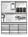
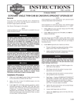
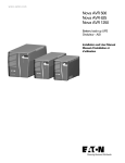
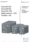
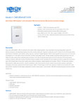
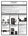
192321932012001
USER’S MANUAL
03/2012
525VA/625VA
IMPORTANT SAFETY INSTRUCTIONS
SAVE THESE INSTRUCTIONS
This manual contains important safety instructions. Please follow all instructions carefully during installation.
Read this manual thoroughly before attempting to unpack, install or operate.
CAUTION- To prevent the risk of fire or electric shock, install in a temperature and humidity controlled
indoor area, free of conductive contaminants.
CAUTION- Risk of electric shock, do not remove the cover. No user serviceable parts. Refer servicing
to qualified service personnel.
CAUTION- Risk of electric shock, hazardous live parts inside this UPS can be energized from the
battery supply even when the input AC power is disconnected.
CAUTION- Risk of electric shock, Battery Circuit is not isolated from AC input, hazardous voltage may
exist between battery terminals and ground. Test before touching.
NOTICE- The UPS is designed to be for use with computer loads only.
CAUTION- This UPS meets Category C2. If used in living area it can cause interference with radio
equipment. Then you need to make additional provisions.
1 Inspection
Inspect the UPS upon receipt. Notify the carrier
and dealer if there is damage. The package is
recyclable; save it for reuse or dispose of it
properly.
SETUP
3 Check the Site Wiring 4 Connect the loads
connect the UPS with the AC Mains, then
Fault Indicator(115V only) First,
plug the loads into the output connectors on the
Caution: If the site wiring fault indicator lights,
get a qualified electrician to correct the building
wiring.
rear of the UPS. To use the UPS as a master
“On/Off” switch, make sure that all of the loads
are switch “On”.
2 Placement
Caution: Do not connect a laser printer to the
outlets. These UPS outlets provide battery
power and surge protection to the equipment
when utility voltage is outside acceptable limits.
5 Connect telephone /
Network Surge
protection
6 Connect Computer
Interface Port(Optional)
7 Operation Test
1. Connect the UPS to the wall receptacle.
2. Push on the Main Switch to check the Green
Connect the supplied interface cable to the 9-pin
Line (
) LED is on.
computer interface port on the back of the UPS.
3. Connect your computer equipment with
Connect a single line telephone or a 10 base-T / Connect to the computer. See software
sockets of the UPS and pull off the input power
100 base-T network cable into the RJ-45 / RJ-11 document for installation instruction.
cable of the UPS from the wall receptacle to
telephone / network surge protection “IN” jack on
the back of the UPS. Connect from the “OUT”
check if the Line (
) LED is flashing every 3
jack with telephone cable (supplied) or network
seconds. Meanwhile, please check if alarm
cabling (not supplied) to a fax modem or network
buzzer is beeping.
port.
4. Try the field working condition by running some
application programs on your computer and
repeating step.
5. Check if the UPS is initiated properly to
support continuous operation.
6. IMPORTANT NOTICE: Plug the UPS
into the wall outlet to charge the UPS for over
8 hours before using the UPS.
7. STORAGE:
Store at -15 to +30 °C (+5 to +86 °F), charge
the UPS battery every six months.
Seite 1 von 2
Store at +30 to +45 °C (+86 to +113 °F),
charge the UPS battery every three months.
FRONT PANEL EXPLANATIONS
1. Line LED (
):
Green LED remains standstill when Utility is
normal.
Green LED flashes every 3 seconds and
simultaneously buzzer alarms continuously
when Utility failure.
Green LED flashes every 3 seconds when the
UPS is in Battery charging mode.
Green LED remains standstill and
simultaneously buzzer alarms continuously
when the UPS is in overload condition.
1
3
REAR PANEL EXPLANATIONS
2
1. AC Inlet
2. Backup Outlets: 3pcs NEMA5-15R or IEC320
3. Computer Interface: True RS232 communication port.
4. RJ11/RJ45 Jacks: MODEM /LAN Protection
5. Site Wiring Fault Indicator: For 115Vac system only.
6. AC Fuse Holder. (W/fuse)
525VA/115Vac/6A
800VA/115Vac/8A
525VA/230Vac/4A
800VA/230Vac/6.5A
625VA/115Vac/8A
625VA/230Vac/6.5A
3
2. Check Battery LED (
):
Red LED flashes every 0.5 seconds and
buzzer alarms every 0.5 seconds when UPS
is in battery low condition.
3. Main Switch:
a. To Control on/off the UPS when Utility is normal.
b. To enable “DC-Start” Function when Utility fails. (To enable DC Start
properly, you are recommended to connect <80% output load with the
UPS only)
P.S. Make sure the computer connected to the UPS is switched on before
enable the "DC-Start" function. You are not recommended to add some
other computer or peripherals after DC-Start function is activated.
1
6
4
3
4
3
4
5
5
5
2
1
6
2
2
1
6
REPLACING THE BATTERY
Note: Once the battery is disconnected,
the loads are not protected from power
outages.
1. Use a cross-type screwdriver to remove the
two front panel screws and slide down the
panel.
2. Gently Pull the battery out of the UPS.
3. Loosen the black wire from the negative (-)
terminal and red wire from the positive (+)
terminal.
4. Connect the battery leads to the new battery.
5. Note: Small sparks at the battery connectors
are normal during connection.
6. Slide the battery into the UPS.
7. Close the front panel and fasten two screws.
8. Dispose of the old battery properly at an
appropriate recycling facility.
TROUBLE SHOOTING
When your UPS malfunctions during operation, you may check the list below for proper adjustment. If the adjustment still be in vain,
please contact your sales agent for help.
Situation
Mains normal but 'Line' LED is not on.
Check Items
1. Is the power switch on?
2. Is the fuse in order?
3. Is the power cord loose?
Battery voltage is too low
'Line' LED flashes every second but no
output
Alarm buzzer beeps continuously when Check to see load status if it is in overload.
Utility is normal.
Alarm buzzer beeps for 10 seconds, then
the UPS is turned off
No LEDs display on the front panel
UPS dose not provide expected back up 1. The UPS’s battery is weak due to recent
time.
outage.
2. The UPS’s battery is near the end of its
service life.
The UPS operates normally, but the site Building wiring error such as missing ground or
wiring fault indicator is lit.
hot to neutral wire reversal.
Solution
1. .Press Main Switch on.
2. Change fuse w/same rating.
3. Re-connect the power cord properly.
Recharge the UPS for 24 hours.
Remove some uncritical load.
Remove some uncritical load and re-switch
on the UPS.
Consult with your sales agent For help.
1. Charge the battery.
2. If the battery is near the end of its service
lift, consider replacing the battery.
Have a qualified electrician correct the
building wiring.
Seite 2 von 2, Advanced Power Systems GmbH & Co. KG, Bayreuther Str. 6, D-91301 Forchheim