1
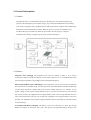
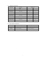
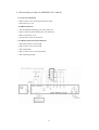
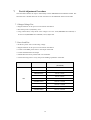
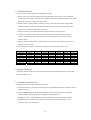
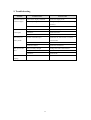
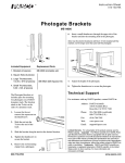
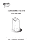
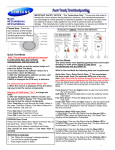
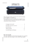
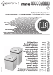
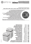
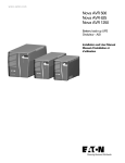
Service Manual
Imperial Series
Model :IMP-425/525/625/825/1000AP
IMD-425/525/625/825/1000AP
IMP-1025/1200/1500/2000AP
IMD-1025/1200/1500/2000AP
Contents of Service Manual
1. Safety Precautions ------------------------------------------------------------------ 2
1.1 Service Warnings ----------------------------------------------------------------- 2
1.2 Important Safety Instructions --------------------------------------------------- 2
2. General Information ------------------------------------------------------------------ 3
2.1 Outline ------------------------------------------------------------------------------ 3
2.2 Features ----------------------------------------------------------------------------- 3
3. SPECIFICATIONS ------------------------------------------------------------------- 5
3.1 Electrical Specifications ----------------------------------------------------------- 5
3.2 Mechanical Specifications--------------------------------------------------------- 7
3.3 Environmental Specifications ----------------------------------------------------- 7
4.
5.
Communications Interface ------------------------------------------------------- 8
Battery Replace Procedure ------------------------------------------------------ 10
5.1
Replacement Procedure for IMP/IMD-425~1000AP--------------------- 10
5.2 Replacement Procedure for IMP/IMD-1025~2000AP------------------- 11
6. Disassembly Procedure ----------------------------------------------------------- 12
6.1 Disassembly procedure for IMP/IMD-425~1000AP ---------------------- 12
6.2 Disassembly procedure for IMP/IMD-1025~2000AP--------------------- 13
7.
Test & Adjustment Procedure ---------------------------------------------------- 14
7.1 Charger Voltage Test ------------------------------------------------------------- 14
7.2 Backup Capacity Test ------------------------------------------------------------ 14
7.3 Transfer Point Test --------------------------------------------------------------- 15
7.4 Startup On Battery --------------------------------------------------------------- 15
7.5 Communications Port Test ------------------------------------------------------- 15
8.
Function Block Diagram ---------------------------------------------------------- 16
8.1 Main structure -------------------------------------------------------------------- 16
8.2 Control circuit -------------------------------------------------------------------- 16
9. Troubleshooting ----------------------------------------------------------------------- 17
1
1. Safety Precautions
1.1 Service Warnings
* The UPS contains voltages what are potentially hazardous. All repairs should be performed by
qualified service person.
* The UPS has its own internal energy source (battery). The output receptacles may be alive even when
the UPS is not connected to an AC supply.
* No modification of any circuit should be attempted. Service work should only be performed after you
are thoroughly familiar with all of the following safety checks and servicing guidelines.
* Safe and continuous operation of the UPS depends partially on the care taken by users. Please
observe the following precautions:
1.Do not attempt to power the UPS from any receptacle except a 2-pole 3-wire grounded receptacle.
2.Do not place the UPS near water or in environments of excessive humidity.
3.Do not allow liquid or any foreign objects to get inside the UPS.
4.Do not plug appliances, such as hair dryers, into the UPS receptacles.
5.Do not place the UPS under direct sunshine or close to heat-emitting sources.
6.This UPS is intended for installation in a temperature controlled, indoor area free of conductive
contaminants.
1.2 Important Safety Instructions
This manual contains important safety instructions. Keep this manual handy for reference.
For continued protection against the risk of fire, replace with the same type / rating of fuses.
While testing the UPS to determine the problem, always use a DC power supply in place of the
batter.
A battery can be present a risk of electrical shock, burns from high short-circuit current, fire of
explosion from vented cases. Observe proper precautions.
When replacing batteries, use the same number and the following type batteries: sealed lead-acid
maintenance free.
Proper disposal of batteries is required. Refer to your local codes for disposal requirements.
There are special components used in this UPS what are important for safety.
These parts are identified by the international symbol "!" on the schematic diagram and on the
replacement parts list. It is essential to replace these critical parts with manufactures' specified parts
to prevent shock, fire or other hazards.
2
2. General Information
2.1 Outline
The Imperial Series are advanced line-interactive simulated sine wave uninterruptible power
systems (UPS) designed to prevent spikes, surges, sags, transients and blackouts from reaching
your sensitive equipment. Your equipment may include such items as computers and computerized
instruments to telecommunication systems. When AC power is present, the UPS filters and
conditions the power continuously. When AC power fails, the unit employs its internal
maintenance-free battery to supply back-up power without interruption.
2.2 Features
Frequency Auto Sensing: The Imperial series UPS can operate in either a 50 or 60 Hz
environment. When you plug the UPS into an AC outlet and turn it on, it will automatically detect
the incoming line frequency and configure itself to match that frequency.
Smart Buck and Boost Line Conditioning: The voltage from your AC power source can fluctuate
above and below the standard rating. This microprocessor controlled UPS provides line conditioning
via both buck (step-down voltage) and boost (step-up voltage) functions. For example, if your
normal voltage is 120V and the voltage fluctuates up to 131V, the buck function in your UPS will
step it down so that your equipment receives approximately 120V. If the voltage fluctuates down to
109V, the boost function will step it up so that your equipment receives approximately 120V. This
provides your equipment with excellent voltage regulation with less possibility for the UPS to drain
its internal battery.
User Replaceable Battery Design: The battery is the most critical part in a UPS. The average
lifetime of a battery is between 3 and 5 years. The special user-replaceable battery design of this
3
UPS provides significant savings and gives the UPS an almost unlimited life. You can replace the
battery very easily, and without turning off your UPS or the equipment it is protecting.
Advanced Interface to Communicate with Computer: Many UPS’s provide only a basic power
failure warning. These models, together with UPSMON also provide you with important operating
information. From your computer screen, you can know input/output voltage and current, frequency,
battery voltage, etc., and analyze power problems. If software is not part of your UPS package, you
can purchase it from your local dealer.
Schedule Shutdown & Startup: Using software you can locally or remotely control the shutdown
and startup of equipment connected to the UPS. A customized schedule can be developed to meet
your specific requirements.
Data-Line Surge Protection: The built-in data-line surge suppression on the rear panel completes
your system protection. It provides an easy way to protect a network (RJ45) or modem (single line
phone) connection from hazardous spikes.
4
3. SPECIFICATIONS
3.1 Electrical Specifications
Battery output rating
Product Name
Frequency
Rated Voltage
Capacity
(Hz)
(V)
(W)
100 / 110 / 115 / 120V
IMP/IMD-425AP
50/60
255W
220 / 230 / 240V
100 / 110 / 115 / 120V
IMP/IMD-525AP
50/60
315W
220 / 230 / 240V
100 / 110 / 115 / 120V
IMP/IMD-625AP
50/60
375W
220 / 230 / 240V
100 / 110 / 115 / 120V
IMP/IMD-825AP
50/60
495W
220 / 230 / 240V
100 / 110 / 115 / 120V
IMP/IMD-1000AP
50/60
550W
220 / 230 / 240V
100 / 110 / 115 / 120V
IMP/IMD-1025AP
50/60
615W
220 / 230 / 240V
100 / 110 / 115 / 120V
IMP/IMD-1200AP
50/60
720W
220 / 230 / 240V
100 / 110 / 115 / 120V
IMP/IMD-1500AP
50/60
900W
220 / 230 / 240V
100 / 110 / 115 / 120V
IMP/IMD-2000AP
50/60
1200W
220 / 230 / 240V
Input Voltage Range
Upper Limit
Rated Voltage+25%
Buck
Rated Voltage+9%
Boost
Rated Voltage-9%
Lower Limit
Rated Voltage-25%
Input/Output Frequency
45Hz – 55 Hz / 55 Hz – 65 Hz
Input (AC mode)
50 Hz / 60 Hz ± 1 Hz
Output (Inverter mode)
5
Wave Form
AC Mode
Sine wave
Back Up Mode
Step wave
Transfer time
Power Failure AC ⇒ Inverter
4 ms (typical)
Spike/Surge protection
Version
Continuous
Single pulse 8/20us
Voltage Vrms
Imax
Joules
100/110/115/120V
175V
6,000A
1050max.
220/230/240V
385V
6,000A
1050max.
Audible Alarm
Battery discharge at power failure
Beep every 2 seconds
Battery approaches final discharge
Beep every half second
Overload
Continuous buzzer
UPS faulty
Continuous buzzer
Battery and Charger
Battery type: Maintenance-free sealed-lead acid. Recharge time 6 to 8 hours typical from total discharge. (The UPS may
be used immediately after discharge but will provide shorter backup time)
Battery Specifications
DC voltage
IMP/D-
IMP/D-
IMP/D-
IMP/D-
IMP/D-
IMP/D-
IMP/D-
IMP/D-
IMP/D-
425AP
525AP
625AP
825AP
1000AP
1025AP
1200AP
1500AP
2000AP
12V
12V
12V
12V
12V
24V
24V
24V
24V
12V
12V
12V
12V
12V
12V
12V
12V
12V
7.2AH
7.2AH
7.2AH
34W
34W
7.2AH
7.2AH
7.2AH
34W
1
1
1
1
1
2
2
2
2
Type
Quantity
6
3.2
Mechanical Specifications:
Product Name
3.3
Dimensions
Weight (Kg)
W × D × H (mm)
Net
Shipping
IMP/IMD-425AP
105*334*168
5.8
6.3
IMP/IMD-525AP
105*334*168
5.8
6.3
IMP/IMD-625AP
105*334*168
6.3
6.8
IMP/IMD-825AP
105*334*168
6.4
6.9
IMP/IMD-1000AP
105*334*168
6.5
7.0
IMP/IMD-1025AP
130*382*192
13.4
14.8
IMP/IMD-1200AP
130*382*192
13.4
14.8
IMP/IMD-1500AP
130*382*192
13.6
15.0
IMP/IMD-2000AP
130*382*192
14.5
15.9
Environmental Specifications:
Operating
Storage and Shipment
0 ~ 40°C (32° ~ 104°F)
-20° ~ +60°C (-4° ~ +140°F)
Humidity
0 ~ 95% (non-condensing)
0 ~ 95% (non-condensing)
Altitude
3,000 m (10,000 ft) (Max.)
12,000 m (40,000 ft) (Max.)
Temperature
7
4.
Communications Interface
The communication port on the rear panel of the UPS allows for connection to a host computer.
When used with UPSMON communication software you will have access to important operating
information. From your computer screen, you can monitor input/output voltage, AC frequency,
battery voltage, etc., and analyze power problems. UPSMON will also initiate automatic graceful
shutdowns during extended power failures.
If UPSMON and a communication cable are not included in your UPS package purchase it
from your local dealer.
The following are some of the parameters you can monitor:
Input Voltage
Indicates the actual input voltage to the UPS when AC power is present
Output Voltage
Indicates the actual output voltage of the UPS
Input Frequency
Indicates the actual Input frequency of the UPS
Output Frequency
Indicates the actual output frequency of the UPS
Battery Voltage
Indicates the actual output DC voltage of the UPS battery
Load Percent
Indicates the percentage of UPS Voltage-Ampere(VA) capacity being
utilized by your equipment
The Imperial Series also supports software which relies on basic "contact closure signals" such as the
built in UPS Service in Windows NT (you will need to purchase a special cable for this type of
application). The major functions of this type of software normally include the following:
* To broadcast a warning when power fails.
* To close any open files before the battery rescues are exhausted.
* To turn off the UPS.
Note: You can connect your computer to your UPS without also connecting to the communication
port. In this case, your UPS warns you of a power failure by beeping, but you have to
manually shut down your UPS and computer.
8
Dsub9 Pin assignments:
Pin No.
RS-232 Signal
Contact Closure Signal
1
2
Tx (UPS > Computer)
3
Rd (Computer > UPS)
4
+12V (Computer > UPS)
5
GND
Shut Down
GND
6
7
AC failure
-12V (Computer > UPS)
8
9
Battery Low
Tx (Short with pin2 )
9
5. Battery Replace Procedure
Changing the batteries in your UPS is a safe and easy procedure. Since the battery is not isolated
from the AC input, you must power off your UPS and unplug the power cord before proceeding
the following procedure.
5.1 Replacement Procedure for IMP/IMD-425~1000AP (Optional function)
1.
Remove the two screws on the battery cover.
2.
Pull and open the cover as the following illustrations. Gently pull out the battery.
3.
Disconnect the two wires connecting the battery to the UPS.
4.
Connect the wires to the new battery, making sure that the red wire is connected to the red
battery terminal and the black wire is connected to the black battery terminal.
5.
Push the new battery into place.
6.
Close the cover, and replace the screws back to the cover.
10
5.2 Replacement Procedure for IMP/IMD-1025~2000AP
1.
2.
3.
4.
5.
6.
7.
8.
9.
10.
Remove the screws on the battery cover.
Pull and open the cover.
Remove the screws of the battery retaining plate.
Pull out the battery.
Disconnect the two wires connecting the battery pack to the UPS
Connect the wires to the new battery pack, making sure that the red wire is connected to the
red battery terminal and the black wire is connected to the black battery terminal.
Push the new battery into place.
Reposition the battery retaining plate and tighten the screws.
Slide the front panel back into place.
Tighten the two small screws on the bottom of the front panel.
Â
Â
Â
11
6.
Disassembly Procedure
6.1
Disassembly procedure for IMP/IMD-425~1000AP
6.1.1 Top Cover Removal
* Turn the UPS off and unplug it from the utility line.
* Remove the 6 screws on the bottom.
* Open the top cover.
6.1.2 Remove the battery wire
* Remove the black wire from PCB to battery.
6.1.3 Removal the PCB and Transformer
* Take off all the wires on the PCB.
* Remove all the screws on the PCB.
* Take off the PCB.
* Take off the transformer.
6.1.4 Remove the rear panel
* Remove the 4 screws on the real panel.
* Take off the rear panel.
12
6.2 Disassembly procedure for IMP/IMD-1025~2000AP
6.2.1 Top Cover Removal
* Remove the 8 screws on the bottom and rear panel.
* Take off the top cover.
6.2.2 Batter Removal
* Turn the UPS off and unplug it from the utility line.
* Remove the front panel and disconnect the LED wire.
* Remove the battery cover.
* Pull the battery out from the chassis.
6.2.3 Removal the PCB and Transformer
* Take off all the wires on the PCB.
* Remove the 5 screws on the PCB.
* Take off the PCB.
* Remove the 4 screws on the transformer.
* Take off the transformer.
13
7.
Test & Adjustment Procedure
This Procedure outlines the steps to functionally test the IMP/IMD-425AP~2000AP models. The
functional test is broken down into several sections to test each different function of the UPS.
7.1 Charger Voltage Test
* Plug the UPS into an AC power source and turn the UPS on.
* Disconnect positive (red) battery wire.
* Using a multi-meter, verify the B+ to B- voltage is at 13.4V~14.0V(IMP/IMD-425~1000AP) or
26.8V~27.8V(IMP/IMD-1025~2000AP). If not, adjust VR1.
7.2 Over Load Test
* Set the AC power source to the rating voltage.
* Plug the UPS into an AC power source and turn the UPS on.
* Connect a true RMS power meter to the output of the UPS.
* Connect the SPS load to the output.
* Add the SPS load slowly till the UPS over load alarm.
* Use the following chart to verify' the power handling capabilities of the UPS.
Load
Product Name
Overload Alarm
(AC Mode)
SPS
IMP/IMD-425AP
425VA~510VA
IMP/IMD-525AP
525VA~630VA
IMP/IMD-625AP
625VA~750VA
IMP/IMD-825AP
825VA~990VA
IMP/IMD-1000AP
1000VA~1200VA
IMP/IMD-1025AP
1025VA~1230VA
IMP/IMD-1200AP
1200VA~1440VA
IMP/IMD-1500AP
1500VA~1800VA
IMP/IMD-2000AP
2000VA~2400VA
14
7.3 Transfer Point Test
* Using a variac, set the output for the rated UPS's voltage.
* Slowly reduce the variac output while monitoring the UPS's input voltage. The UPS should
transfer to Boost when the voltage drops to the level given in the following Transfer Point Chart.
Repeat this procedure to ensure accurate results.
* While the UPS is in Boost mode. continue to slowly reduce the variac output until the UPS
transfers to battery mode. The UPS should transfer to battery when the voltage drops lo the
level given in the following Transfer Point Chart.
* Slowly increase the variac output until the UPS goes back to on-line operation.
* Continue to increase the variac output until the UPS transfers to Buck when the voltage
increases to the level shown in the Transfer Point Chart. Repeat this procedure to ensure
accurate results.
* While the UPS is in Buck mode, continue to slowly increase the variac output until the UPS
transfers to battery mode.
* Check the output voltage for each step according to the Transfer Point Chart. Load
Hi to INV
INV Hi recover
Buck
Buck Recover
Boost Recover
Boost
INV Low recover
Low to INV
100V
122–128
118–124
106–112
103–109
91–97
88–94
76–82
72–78
110V
134–141
130–136
117–123
113–120
100–107
97–103
84–90
79–86
115V
140–147
135–143
122–129
118–125
104–112
101–108
87–94
83–90
120V
146–154
142–149
127–134
124–131
109–116
106–113
91–98
86–94
220V
268–282
260–273
233–246
227–240
200–213
194–207
167–180
158–172
240V
281–294
271–285
244–258
237–251
209–223
202–216
175–189
166-179
240V
293–307
283–298
254–269
247–262
218–233
211–226
182–197
173–187
7.4 Startup On Battery
Unplug the UPS from the variac, and press the front panel On/Off button for three seconds, and
the UPS should turn on
7.5 Communications Port Test
* Plug the UPS into the variac and turn on the UPS.
* Connect the USB or 9 pin communication cable (721-9266-dd8) between the computer com port
and UPS com port.
* Start the UPSMON Monitor & Manager programs and verify the information is displayed
correctly (Model, Voltage/Frequency Configuration, Input/Output etc...).
* UPSMON will also initiate automatic graceful shutdowns during extended power failures.
* If UPSMON and a communication cable are not included in your UPS package, you can
purchase it from your local dealer.
15
8.
Function Block Diagram
8.1 Main structure
8.2 Control circuit
16
9. Troubleshooting
Problem
Possible Cause
Action to take
UPS can’t turn on
Switch on the display board fail
Replace the display PCB
( LED not light)
Per Battery voltage less than 9V
Recharge the ups at least 8 hours, or change
the battery.
PCB failure
Replace the PCB
UPS can’t turn on
Battery failure
Replace the battery
( LED light)
PCB failure
Replace the PCB
Transformer failure
Replace the transformer
AC Fuse or breaker open
Replace the AC fuse in inlet or reset the
UPS always at
battery mode
circuit breaker.
PCB Failure
Replace PCB
Transformer failure
Replace the transformer
Back up time too
Battery not fully charged
Recharge the UPS at least 8 hours
short
Battery too old
Replace Battery, call for service
PCB failure
Replace PCB
Buzzer continuous Overload
Replace PCB
beeping
17