1
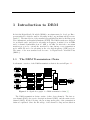
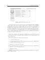
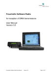
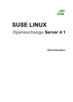
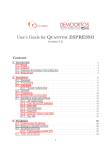
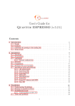
SPARK
Software Modulator for
Digital Radio Mondiale (DRM)
User Manual
Version:
1.0
Autor:
Michael Feilen
Br¨
uckenstraße 22
54347 Neumagen-Dhron
[email protected]
Last changed:
16th August 2009
First published:
07th July 2009
Contents
1 Introduction to DRM
1
1.1
The DRM Transmission Chain . . . . . . . . . . . . . . . . . . . .
1
1.2
Energy Dispersal . . . . . . . . . . . . . . . . . . . . . . . . . . .
2
1.3
Channel Coding . . . . . . . . . . . . . . . . . . . . . . . . . . . .
2
1.4
Orthogonal Frequency Division Multiplexing (OFDM) . . . . . . .
2
1.5
OFDM Framing . . . . . . . . . . . . . . . . . . . . . . . . . . . .
2
1.6
The DRM Data Channels . . . . . . . . . . . . . . . . . . . . . .
3
1.6.1
Fast Access Channel (FAC) . . . . . . . . . . . . . . . . .
3
1.6.2
Service Description Channel (SDC) . . . . . . . . . . . . .
3
1.6.3
Main Service Channel (MSC) . . . . . . . . . . . . . . . .
3
2 Introduction to Spark
2.1
2.2
4
Functionality . . . . . . . . . . . . . . . . . . . . . . . . . . . . .
4
2.1.1
Audio Streams . . . . . . . . . . . . . . . . . . . . . . . .
4
2.1.2
Data Streams . . . . . . . . . . . . . . . . . . . . . . . . .
5
2.1.3
Time Synchronisation
. . . . . . . . . . . . . . . . . . . .
5
2.1.4
Output . . . . . . . . . . . . . . . . . . . . . . . . . . . . .
5
2.1.5
Realtime Operation . . . . . . . . . . . . . . . . . . . . . .
5
2.1.6
Reliability . . . . . . . . . . . . . . . . . . . . . . . . . . .
5
2.1.7
Restrictions . . . . . . . . . . . . . . . . . . . . . . . . . .
5
Requirements . . . . . . . . . . . . . . . . . . . . . . . . . . . . .
6
2.2.1
Hardware requirements . . . . . . . . . . . . . . . . . . . .
6
2.2.2
Software requirements . . . . . . . . . . . . . . . . . . . .
6
i
3 Spark User Manual
8
3.1
The Application Window . . . . . . . . . . . . . . . . . . . . . . .
8
3.2
The Transmitter Settings . . . . . . . . . . . . . . . . . . . . . . .
10
3.2.1
DRM Settings . . . . . . . . . . . . . . . . . . . . . . . . .
10
3.2.2
AM Settings . . . . . . . . . . . . . . . . . . . . . . . . . .
13
3.2.3
MDI settings . . . . . . . . . . . . . . . . . . . . . . . . .
15
3.2.4
Output Settings . . . . . . . . . . . . . . . . . . . . . . . .
17
3.2.5
Output Settings / Modulation . . . . . . . . . . . . . . . .
17
3.2.6
Output Settings / OFDM Postprocessing . . . . . . . . . .
18
3.2.7
Output Settings / PCM Output Devices . . . . . . . . . .
20
Content Manager Configuration . . . . . . . . . . . . . . . . . . .
20
3.3.1
Introduction to streams and substreams . . . . . . . . . .
21
3.3.2
AAC Stream . . . . . . . . . . . . . . . . . . . . . . . . .
23
3.3.3
PRBS Stream . . . . . . . . . . . . . . . . . . . . . . . . .
27
3.3.4
Packet Datastream . . . . . . . . . . . . . . . . . . . . . .
27
3.3.5
Packet Datastream / MOT Slideshow Substream . . . . .
28
3.3.6
Packet Datastream / MOT Website Substream . . . . . .
30
3.3.7
Services . . . . . . . . . . . . . . . . . . . . . . . . . . . .
31
3.4
The Time Reference Settings . . . . . . . . . . . . . . . . . . . . .
35
3.5
Control Panel . . . . . . . . . . . . . . . . . . . . . . . . . . . . .
37
3.5.1
Starting and Stopping the Transmission . . . . . . . . . .
37
3.5.2
Open and Save the Application Settings . . . . . . . . . .
37
3.5.3
Text Message Reconfiguration . . . . . . . . . . . . . . . .
38
3.3
ii
List of Figures
1.1
Signal flow graph of a DRM transmission chain [1]. . . . . . . . .
1
3.1
The Spark application window. . . . . . . . . . . . . . . . . . . .
8
3.2
The multiplex information panel with a content manager example
configuration. . . . . . . . . . . . . . . . . . . . . . . . . . . . . .
9
3.3
DRM settings input box. . . . . . . . . . . . . . . . . . . . . . . .
10
3.4
AM settings input box. . . . . . . . . . . . . . . . . . . . . . . . .
14
3.5
MDI settings input box. . . . . . . . . . . . . . . . . . . . . . . .
15
3.6
Output settings input box. . . . . . . . . . . . . . . . . . . . . . .
17
3.7
The modulation panel in the output settings tree. . . . . . . . . .
18
3.8
Analog output device input box. . . . . . . . . . . . . . . . . . . .
20
3.9
Content manager tab showing an example AAC configuration and
the buttons to create new audio or data streams. . . . . . . . . .
21
3.10 The bitrate suggestion dialog appears before a new stream is created. 23
3.11 Opening the configuration dialog of a stream. . . . . . . . . . . .
23
3.12 AAC stream configuration dialog. . . . . . . . . . . . . . . . . . .
24
3.13 The text message input dialog in the AAC configuration panel. . .
26
3.14 The configuration dialog of a PRBS data stream. . . . . . . . . .
27
3.15 The packet datastream configuration dialog. . . . . . . . . . . . .
28
3.16 MOT slideshow substream configuration dialog. . . . . . . . . . .
29
3.17 MOT website substream configuration dialog. . . . . . . . . . . .
30
3.18 Create a new service pointing to an existing Dolby AAC+ audio
stream. . . . . . . . . . . . . . . . . . . . . . . . . . . . . . . . . .
32
3.19 Four services pointing to the same stream. . . . . . . . . . . . . .
32
3.20 A service pointing to an audio and a data stream at the same time. 33
3.21 Change the service-to-stream assignment. . . . . . . . . . . . . . .
33
3.22 Edit the service parameters. . . . . . . . . . . . . . . . . . . . . .
34
iii
3.23 The service parameters. . . . . . . . . . . . . . . . . . . . . . . .
34
3.24 The time reference tab. . . . . . . . . . . . . . . . . . . . . . . . .
36
3.25 Button to start the transmission. . . . . . . . . . . . . . . . . . .
37
3.26 Button to stop the transmission. . . . . . . . . . . . . . . . . . . .
37
3.27 Buttons to open and save the application settings. . . . . . . . . .
38
3.28 A successful read operation is indicated by a green flashing background of the open button. . . . . . . . . . . . . . . . . . . . . . .
38
3.29 The text message reconfiguration button. . . . . . . . . . . . . . .
38
iv
List of Tables
3.1
OFDM bandwidth and the supported DRM robustness modes. . .
11
3.2
MSC mapping schemes.
. . . . . . . . . . . . . . . . . . . . . . .
12
3.3
SDC mapping schemes. . . . . . . . . . . . . . . . . . . . . . . . .
12
3.4
Interleaver configuration. . . . . . . . . . . . . . . . . . . . . . . .
13
3.5
Spark output transmission modes. . . . . . . . . . . . . . . . . . .
17
3.6
Available PCM output devices. . . . . . . . . . . . . . . . . . . .
20
3.7
Available audio and data streams in Spark. . . . . . . . . . . . . .
22
3.8
Audio input devices for the AAC stream. . . . . . . . . . . . . . .
25
v
Abbreviations
AAC
AGC
AM
AMSS
BIOS
DAQ
DCP
DRM
EEP
ETSI
FAC
FEC
FFT
FIR
GMT
HmMix
HmSym
HPP
IF
ISI
JRE
JVM
LGPL
LPP
MDI
MLC
MOT
MPEG
MSC
NTP
OFDM
PCM
PFI
PFT
Advanced Audio Coding
Automatic Gain Control/Correction
Amplitude Modulation
Amplitude Modulation Signalling System
Basic Input and Output System
Data Acquisition
Distribution and Communication Protocol
Digital Radio Mondiale
Equal Error Protection
European Telecommunications Standards Institute
Fast Access Channel
Forward Error Correction
Fast Fourier Transform
Finite Impulse Response
Greenwich Mean Time
Mixed Hierarchical Mapping
Symmetrical Hierarchical Mapping
Higher Protected Part
Intermediate Frequency
Inter-Symbol-Interference
Java Runtime Environment
Java Virtual Machine
Lesser General Public License
Lower Protected Part
Multiplex Distribution Interface
Multi-Level Coding
Multimedia Object Transfer
Motion Experts Picture Group
Main Service Channel
Network Time Protocol
Orthogonal Frequency Division Multiplexing
Pulse Code Modulation
Programmable Function Interface
Protection Fragmentation and Transportation
vi
PRBS
QAM
QPSK
RF
SBR
SDC
SDR
SM
TF
TSF
UDP
UEP
UTF
VHF
VSPP
XOR
Pseudo Random Binary Sequence
Quadrature Amplitude Modulation
Quadrature Phase Shift Keying
Radio Frequency
Spectral Bandwidth Replication
Service Description Channel
Software Defined Radio
Standard Mapping
Transmission Frame
Transmission Super Frame
User Datagram Protocol
Unequal Error Protection
Unicode Transformation Format
Very High Frequency
Very Strongly Protected Part
Exclusive Or
vii
1
1 Introduction to DRM
In 1998 the Digital Radio Mondiale (DRM) consortium started to develop a European standard for digital sound broadcasting in the long, medium and short wave
bands [1]. The first version of the standard was published in 2003 by the European
Telecommunications Standards Institute (ETSI). The DRM system was designed
for worldwide audio and data broadcasting in frequency domains below 30 MHz
and for channel bandwidths from 4.5 kHz to 20 kHz. In 2004 the consortium
members proposed to extend the standard by introducing a new transmission
mode which allows for broadcasting in the very high frequency (VHF) regions.
The name of the new standard was chosen to be Digital Radio Mondiale Plus
(DRM+ ).
1.1
The DRM Transmission Chain
A schematic overview of the DRM transmission chain is shown in Figure 1.1.
Figure 1.1: Signal flow graph of a DRM transmission chain [1].
The DRM transmission chain consists of three data channels: The fast access channel (FAC), the service description channel (SDC), and the main service
channel (MSC). In the following, the most important parts of the transmission
chain are explained. Since the knowledge of the channel coding and modulation
2
1. Introduction to DRM
schemes is required in order to depict the properties of the DRM data channels,
the explanation begins with the description of the energy dispersal stage.
1.2
Energy Dispersal
Before channel coding, each bitstream is processed by a scrambler stage. The
XOR pattern for the scrambler is derived from a pseudo random binary sequence
(PRBS) generator with generator polynomial x9 + x5 + 1.
1.3
Channel Coding
The scrambled bits are forwarded to a convolutional encoder with a mother code
rate of 1/6 and 6 bit constraint length, where the generated code is terminated
by an all-zero input sequence. Different puncturing patterns can be applied in
order to select the desired output code rate. Additionally, tail-bit-puncturing is
used. For audio or data content, DRM supports four different code rates which
can be chosen from a protection level table in order to meet the coding gain
requirements. After channel coding, the bits are interleaved over one frame by a
convolutional interleaver and forwarded to the modulation stage.
1.4
Orthogonal Frequency Division Multiplexing (OFDM)
DRM uses OFDM, a multicarrier modulation scheme that is widely used in modern digital broadcasting applications. The idea of multicarrier transmission is to
first split the multiplex bitstream into different substreams and then to encode
these streams in parallel, e.g. by using multilevel coding (MLC). Subsequently,
the bits of each individual substream are mapped onto one of the NC subcarriers
by shaping the carrier’s amplitude and phase according to a predefined mapping function. Different mapping functions and different constellation types are
available.
1.5
OFDM Framing
The OFDM framing in DRM is strictly hierarchical. The top level framing unit
is the transmission super frame (TSF) which contains a sequence of transmission
frames (TF). Each transmission frame wraps NSYM OFDM symbols.
1.6. The DRM Data Channels
1.6
3
The DRM Data Channels
The internal data structure of DRM is depicted in Figure 1.1. There are three
different channels serving different purposes, each of them is briefly explained in
the following subsections.
1.6.1
Fast Access Channel (FAC)
The FAC cells are included in every transmission frame and carry information
about the OFDM configuration and other system settings. The fixed code rate
and the position of the QPSK symbols close to the reference cells make the FAC
very robust. Reliable access to the data of the FAC is necessary to provide the
receiver with the information needed to decode the SDC and MSC.
1.6.2
Service Description Channel (SDC)
The SDC contains information on the streams and services, included in the MSC
multiplex. In DRM mode the SDC can be configured to use either 4 QAM or
16 QAM modulation and a fixed code rate of r = 0.5. In DRM+ mode the SDC
can be configured to use the code rates r = 0.5 or r = 0.25 but the modulation
is fixed to 4 QAM. In both modes the encoded cells are mapped onto the first
couple OFDM symbols within a TSF.
1.6.3
Main Service Channel (MSC)
The MSC carries the precoded and multiplexed digital media content. In DRM+ mode
the constellation mapping can be chosen to be either 4 or 16 QAM together
with different code rates. In DRM mode, the MSC modulation is restricted to
16 QAM or 64 QAM. The MSC allows for the use of unequal error protection
(UEP), where the multiplex frame is split into higher and lower protected parts
by using separate code rates for each respective part1 . Additionally, the MSC
uses a convolutional QAM cell interleaver, which makes the main service channel
less vulnerable to multi-path fading.
1
In the DRM standard the available code rates for the higher and lower protected parts are
subdivided into four different protection levels.
4
2. Introduction to Spark
2 Introduction to Spark
2.1
Functionality
Spark is a realtime software modulator for DRM, DRM+ and AM. It combines
DRM content server and modulator capabilities in one software defined radio
(SDR) application. Additionally, Spark supports the multiplex distribution interface (MDI) which allows to broadcast the multiplex content over ethernet.
Along with the software, a graphical user interface is provided for setting up
the DRM signal parameters (e.g. audio bit rate, transmission mode, spectrum
occupancy), the stream sources and destinations (e.g. sound card or file) and the
service information (e.g. Station Label).
2.1.1
Audio Streams
Spark is able to acquire audio signals from the line input of a PC soundcard,
from a wave file of the format (RIFF, 16 bit, 48 kHz, Stereo) or from MP3
files. For testing purposes, the LGPL open-source AAC library FAAC can be
used which does not support stereo or SBR transmissions. For full AAC+ audio
coding a ”DRM Audio Encoder Library Module” for MPEG AAC+SBR coding available from Dolby, Deutschherrnstr. 15-19, D-90429 Nuernberg, Germany,
(http://www.dolby.com) can be licensed. The software library can be licensed to
the client through the developer which has an according contract with Dolby.
DRM text messages can be entered directly using the PC keyboard in the
input dialogue of the audio stream. A number of text messages can be sent
cyclically (text carousel) with an adjustable repetition for each message. Text
message reconfiguration during transmission is supported.
2.1. Functionality
2.1.2
5
Data Streams
The software supports the multimedia object transfer (MOT) data protocol. The
supported applications are MOT Broadcast Website and MOT Slideshow. Additionally, Spark supports the transmission of pseudo random binary sequences
(PRBS) as specified in [2]. The files for MOT operation can be read from the
drives of the operating system.
2.1.3
Time Synchronisation
The software automatically acquires the time by one of the network time protocol
(NTP) servers specified in the time input dialog during modulation. If there is no
NTP server available, the BIOS clock of the PC on which the software is running
can be used.
2.1.4
Output
The DRM multiplex can either be modulated or send over an IP network using the
MDI. The MDI protocol specification version 1.1.1 is fully implemented. However,
the distribution and communications protocol (DCP) does not support ReedSolomon forward error correction (FEC).
2.1.5
Realtime Operation
Realtime operation of the software is possible. Due to internal buffering, the
overall delay between the analogue audio input and the DRM signal output will
be in the order of 3 to 5 seconds.
2.1.6
Reliability
The software is stable and has been tested in a permanent setup without any
indications of instability or other problems. The stability of the Java virtual
machine running on the host PC cannot be guaranteed.
2.1.7
Restrictions
The following restrictions on the functionality and the operation of the software
apply:
6
2. Introduction to Spark
• Up to four audio streams can be used can be used for generation of the DRM
signal. The DRM Multiplex is static, reconfiguration during operation is
not supported (reconfiguration index = 0).
• Only data entities of the types 0, 1, 5, 8, 9, 10, 12 are generated.
• For audio coding, only AAC is possible.
• The decodability of the DRM signal output of Spark was successfully verified with the Morphy Richards DRM receiver, the Fraunhofer Softwareradio
v4.0.4, the DIORAMA software receiver and the DREAM software receiver
version 1.1.4. The MDI interface and MDI transmitter application was
tested with the Fraunhofer (FhG) Softwareradio. However, the full compliance according to [1] can not be guarantueed.
• The jitter and frequency accuracy of the analogue output signal is limited by
the output hardware. This may lead to a situation where the RF frequency
accuracy required by frequency managing authorities may not be met.
2.2
2.2.1
Requirements
Hardware requirements
The hardware requirements for Spark strongly depend on the configuration of the
software. The minimum hardware requirements for Spark are fulfilled by a PC
with an 800 MHz CPU and with 128 MB of RAM dedicated to the applicaten.
Given these constraints Spark will run stable in DRM mode at output sample
rates of not more than 48 kHz and not more than 2 AAC streams. However, the
user might observe signal dropouts as well as insufficient input delays.
In order to run Spark stable at sample rates above 48 kHz, a PC with a 2.0
GHz dual core CPU togther with a minimum of 512 MB RAM reserved for the
application is recommended.
2.2.2
Software requirements
The Spark user interface as well as the baseband algorithms are written in Java
and require the Java Virtual Machine (JVM) which is included in the Java Runtime Environment (JRE). Spark has been developed to work with the JRE version
6.0 or above. Note that it is not recommended to use JRE versions prior to JRE
1.6 update 13 together with the software.
2.2. Requirements
7
Since the main components of Spark are written in Java, the application is in
general platform independent. However, due to the native library support, which
is used for the FFT, the AAC encoder and the native input and output devices,
the range of operating systems to run Spark on is limited to Microsoft Windows
and Linux platforms. Although it is possible to provide native support for other
operating systems, the support for third party libraries (e.g. Dolby AAC+) can
not be guarantueed.
8
3. Spark User Manual
3 Spark User Manual
3.1
The Application Window
After Spark has been started and preconfigured the main window is shown as
depicted in Figure 3.1.
Figure 3.1: The Spark application window.
The configuration window in the center of the screen comprises of three
tabs: the transmitter tab, the content manager tab and the time tab. The
functionality of each tab will be explained in the following:
3.1. The Application Window
9
• Transmitter tab: In the transmitter configuration panel, the transmission
mode and the output devices can be configured. Details on the transmitter
settings can be found in Section 3.2.
• Content Manager tab: The content manager contains the stream and
service information together with the input device configuration. The content manager settings are explained in Section 3.3.
• Time tab: The time configuration window contains the NTP time reference configuration and other time reference related settings. The time
reference related parameters are discussed in Section 3.4.
The settings of the panels in the different tabs can be saved and loaded by the
oval open and save buttons in the control panel on the top-right hand side of
the main window. The oval button with the green arrow in the control panel can
be used to start or stop the transmitter, i.e. the DRM+ , AM modulation or the
MDI broadcast. Additionally, the control panel contains a text-button for text
message reconfiguration. This button becomes active after the transmission has
been started and is inactive as long as the modulator is idle. Detailed information
on the control panel functionalities can be found in Section 3.5.
Figure 3.2: The multiplex information panel with a content manager example
configuration.
On the bottom, the main window contains the multiplexer panel which
gives an overview of the available multiplexer bandwidth for the current content
manager configuration and which furthermore indicates the bandwidth consumption of the streams that have been added to the content manager. An example
configuration of the multiplex bandwidth information panel is shown in Figure 3.2.
In the following sections the available configuration options and the different
configuration parts are explained.
10
3. Spark User Manual
3.2
The Transmitter Settings
The transmitter settings tab contains the configuration parameters for the modulation and the output devices. It comprises of the four different submenus:
• DRM Settings: The DRM settings submenu contains the configuration
options for the DRM OFDM configuration and the DRM channel coding
configuration for the channels MSC and SDC.
• AM Settings: The AM settings submenu contains the configuration options for the AM transmission.
• MDI Settings: The MDI settings submenu contains the options for the
DRM MDI transmission over IP.
• Output Settings: In the output settings submenu the transmission mode
can be configured as well as the PCM output devices for OFDM transmission.
3.2.1
DRM Settings
Figure 3.3 shows the available parameters in the DRM settings input box. In the
following each parameter is briefly explained.
Figure 3.3: DRM settings input box.
3.2. The Transmitter Settings
11
Robustness Mode and OFDM bandwidth
The robustness mode defines the OFDM subcarrier spacing and the OFDM
pilot configuration [1]. The spectrum occupancy of the OFDM signal is defined as
OFDM bandwidth. The higher the OFDM subcarrier spacing and the higher
the number of pilot cells, the higher the robustness of the transmission but the
lower the available MSC datarate.
In DRM there exist five different robustness modes, whereas each mode is
compatible to a different set of OFDM bandwidths. Therefore, a reconfiguration
of the robustness mode may force a reconfiguration of the OFDM bandwidth parameter. Changing the robustness mode may also induce a DRM mode change
as the robustness modes A,B,C and D are specified for DRM up to 30 MHz and
robustness mode E defines a DRM+ transmission in the VHF region. A detailed
overview of the different robustness modes and OFDM bandwidth configurations
is given in Table 3.1.
OFDM bandwidth [Hz]
Robustness mode
DRM mode
4,500
5,000
9,000
10,000
18,000
20,000
100,000
A,B
A,B
A,B
A,B,C,D
A,B
A,B,C,D
E
DRM
DRM
DRM
DRM
DRM
DRM
DRM+
Table 3.1: OFDM bandwidth and the supported DRM robustness modes.
SDC and MSC mapping
The parameters for MSC mapping and SDC mapping define the mapping
of the multi-level channel coder (MLC) output bits onto a QAM cell for each
respective channel. The acronym QAM stands for quadrature amplitude modulation, where the phase and the amplitude of the transmitted carrier are shaped
by a certain mapping function as stated in Section 1.4.
In DRM it is distinguished between standard mapping (SM) and hierarchical
mapping, where the hierarchical mapping is subpartitioned into mixed hierarchical mapping (HmMix) and symmetrical hierarchical mapping (HmSym). When
HmSym is used hierarchical modulation is performed on both, the inphasal (I)
12
3. Spark User Manual
and the quadrature (Q) component, respectively, whereas in case of HmMix only
the inphasal component is modulated hierarchically. MSC hierarchical mapping
is available only in 64 QAM mode. The available MSC and SDC mapping schemes
are listed in Table 3.2 and Table 3.3, respectively.
NOTE: When hierarchical mapping is used the data of the first stream in the
multiplexer (stream ID equal to zero) is transmitted in the so called hierarchical
data part. Therefore it is important that the number of bits for the multiplex
stream with ID 0 is less or equal to the number of bits available for the hierarchical
part. Furthermore, the hierarchical data part must not have a higher protected
part, i.e. the use of UEP in the stream with ID 0 is permitted.
Mapping scheme
Resolution
Standard Mapping
4 QAM
Standard Mapping
16 QAM
Standard Mapping
64 QAM
Symmetrical Hierarchical Mapping (I and Q) 64 QAM
Mixed Hierarchical Mapping (I only)
64 QAM
DRM mode
DRM+
DRM, DRM+
DRM
DRM
DRM
Table 3.2: MSC mapping schemes.
Mapping scheme
Resolution
DRM mode
Standard Mapping
Standard Mapping
4 QAM
16 QAM
DRM, DRM+
DRM
Table 3.3: SDC mapping schemes.
MSC cellinterleaving
The MSC QAM cells are interleaved over a certain number of transmission frames
in order to increase the signal robustness in case of burst errors, e.g in a channel
environment with flat multipath fading. The higher the interleaver depth, the
longer the delay between signal acquisition and the audio playback at the receiver.
Table 3.4 summarizes the available MSC cell interleaver parameters subject to
the different DRM modes.
3.2. The Transmitter Settings
13
Interleaver depth
Duration [ms]
DRM mode
1 (short)
5 (long)
6
400
2000
600
DRM
DRM
DRM+
Table 3.4: Interleaver configuration.
MSC and SDC protection
The protection level reflects the code rate for the respective part of the MSC or
the SDC bitstream. The lower the code rate, the more redundancy information
is added in the process of channel coding. Although a smaller code rate increases
the robustness of the transmitted information it decreases the number of usable
information bits. Concerning the MSC, DRM distinguishes between the lower
protected part (LPP), the higher protected part (HPP) and the very strongly
protected part (VSPP). If the protection levels for LPP and HPP are equal, the
MSC is said to use equal error protection (EEP). If the protection levels are
different the MSC is said to use unequal error protection (UEP). The VSPP protection level defines the coderate for the hierarchical data part. Since the VSPP
is only present when hierarchical modulation is used, the field is disabled when
using standard mapping for the MSC.
NOTE: Different protection levels for the SDC are only available in DRM+ mode,
i.e. when using robustness mode E.
Spark displays the protection level as a number from zero to four as defined in
the DRM specification [1] followed by one of the following robustness indicators:
highest, high, medium and weak.
3.2.2
AM Settings
The AM settings panel contains the configuration for the amplitude modulation
functionality of Spark. The available input options in the AM settings panel are
shown in Figure 3.4.
The user can specify the audio bandwidth as well as the modulation mode
and modulation degree.
14
3. Spark User Manual
Figure 3.4: AM settings input box.
Audio bandwidth
The audio bandwidth can be adjusted according to the AM channel bandwidth,
which is typically 4.5 or 5 kHz.
Modulation degree
The modulation degree indicates the ratio of the peak modulation signal amplitude, i.e. the maximum audio signal amplitude, to the peak amplitude of the carrier. If the peak amplitude of the modulation signal is half the carrier amplitude,
the modulation degree is 0.5. If the peak amplitudes are equal, the modulation
degree is 1. In Spark, the modulation degree can be adjusted between 0.1 and
1.0.
AM mode
The AM mode describes the position of the output spectrum relative to the carrier
frequency. In Spark, the user can choose between lower sideband, upper sideband
and double sideband modulation. Lower sideband means the output spectrum
is located at the left hand side of the carrier. Upper sideband indicates that
the position of the output spectrum is at the right hand side of the modulation
frequency. In case of double sideband modulation the spectrum is symmetrical
around both sides of the carrier frequency.
Carrier suppression
To achieve a better output power efficiency carrier suppression can be enabled.
When carrier suppression is enabled the power of the carrier is reduced by approximately 12 dB.
3.2. The Transmitter Settings
15
Enable AMSS
When the amplitude modulation signalling system (AMSS) is enabled, the service
information such as the service label, the service identifier and other information
is send by phase modulation of the AM carrier. For more information on AMSS
please refer to [3].
3.2.3
MDI settings
The MDI settings panel contains the configuration options for the distribution
and communication protocol (DCP) [4] and other protocol-specific settings.
Figure 3.5: MDI settings input box.
Use PFT layer
The protection, fragmentation and transportation (PFT) layer is used for data
framing, data encoding as well as source and destination addressing. If the use
PFT layer button is disabled, the MDI communication carried out on the AF
layer only.
Use PFT transport layer
The PFT layer includes a transport layer where the packet source (transmitter)
can be identified by a 16 bit source ID and a packet destination (receiver) can be
identified by a 16 bit destination ID. In a network with multiple MDI transmitters
16
3. Spark User Manual
and receivers this enables to specifically address one particular MDI packet destination and to identify one particular MDI packet source. Disabling the transport
layer button disables this addressing feature.
Use multicasting
If the Use multicasting button is enabled the MDI packets can be send to a
group of MDI receivers. Note that in case of multicast transmissions the Dest.
IP address input field must contain a multicast IP address within the address
range 224.0.0.0 to 239.255.255.255 (IPv4).
Timestamp delay
The timestamp delay defines the number of seconds added to each timestamp
that is generated and transmitted in the MDI output stream. The timestamp
is generated by the time reference (e.g. NTP) which is specified in the time
configuration tab of the configuration tab panel. For a detailed overview of the
MDI timestamp functionality please refer to [5].
PFT source ID
The PFT layer source ID of the MDI packet source (transmitter) must be in the
range of 0 to 65535 (see Use PFT transport layer ).
PFT destination ID
The PFT layer destination ID of the MDI packet sink (receiver) must be in the
range of 0 to 65535 (see Use PFT transport layer ).
Destination IP address
The IP address of the MDI packet sink (receiver) must be entered in the Dest.
IP address input field.
Destination UDP port
The UDP port number for the DCP-MDI packet communication (default: 6001)
must be entered in the Dest. UDP port input field.
3.2. The Transmitter Settings
3.2.4
17
Output Settings
The output settings dialog contains the settings for the PCM output devices,
the transmission mode, the settings for the OFDM signal generation and the
modulation settings as shown in Figure 3.6.
Figure 3.6: Output settings input box.
Transmission mode
The transmission mode defines the output operation of Spark. The user can
choose between the following output modes:
Output mode
Description
DRM over OFDM
Modulated DRM OFDM signal output over
a PCM output device, e.g. a soundcard.
DRM data packets transmitted over ethernet
by using the MDI interface.
Amplitude modulated audio signal output
over a PCM output device, e.g. soundcard.
DRM over MDI
AM and AMSS
Table 3.5: Spark output transmission modes.
3.2.5
Output Settings / Modulation
The modulation panel contains the output settings for the output modulator as
depicted in Figure 3.7. The modulation settings only affect the OFDM and AM
transmission modes.
18
3. Spark User Manual
Figure 3.7: The modulation panel in the output settings tree.
Intermediate frequency (IF)
The intermediate frequency defines the frequency in Hz to which the complex
baseband signal is shifted after modulation.
Output frequency
The output frequency defines the frequency in Hz to which the real PCM output
IF signal is shifted by an external hardware device. This box is disabled if no
external device (e.g a DiRaGen modulator) was found.
Invert baseband spectrum
If the Invert baseband spec. button is enabled the baseband spectrum will be
inverted before modulation. Hence, the new complex baseband signal is the
complex conjugate of the original complex baseband signal.
3.2.6
Output Settings / OFDM Postprocessing
FIR filtering
If the FIR filtering button is enabled the FIR output filter will be used to shape
the OFDM signal in order to reduce the sideband emissions. The FIR filter
parameters are calculated using the Kaiser windowed sinc design method.
NOTE: Using the FIR filter causes inter-symbol-interference (ISI). However, the
influence of ISI is negligible in most cases.
Sideband suppression
The sideband suppression defines the attenuation of the output signal from the
beginning to the end of the transition region. The higher the sideband suppression
the more filter coefficients are required for adequate image rejection and the
3.2. The Transmitter Settings
19
higher the computational complexity.
Recommendation for DRM and DRM+ : 50 dB
Transition bandwidth
The transition bandwidth parameter modifies the steepness of the filter transition
region and is given in Hz. A small transition bandwidth requires a higher filter
order but gives a steeper sideband rolloff.
Recommendation for DRM: 500 Hz
Recommendation for DRM+ : 2500 Hz
FIR coefficient file
In the FIR coefficient file input field an ASCII file can be specified, which must
contain the FIR filter coefficients for the OFDM output signal filtering. If no file
is specified, Spark designs an adequate OFDM signal filter.
The coefficients in the file must be separated by a newline character (\n).
Comments in the file must start with two forwardslashes (//) and must not be
placed before coefficients.
Example of an FIR coefficient file:
// This is a comment
-0.000000228647259
0.000000925740866
-0.000001940961649
-0.000002204589717
0.000001358034607
...
-0.000000228647259
Enable output AGC
The automatic gain correction (AGC) algorithm scales the output signal with
respect to the Gain value, specified in the output device input panel, in order to
reach the maximum PCM output device resolution. When the output AGC is
disabled the OFDM signal power per carrier is equal to power given in the DRM
specification, i.e. the gain value of the output device is ignored.
20
3.2.7
3. Spark User Manual
Output Settings / PCM Output Devices
In this subsection the different PCM output devices can be configured. Furthermore, the user can choose the current output device as well as the output
buffersize.
For each output device the output gain, the number of channels, the sample
resolution in bits per sample and the sample rate can be specified.
PCM output device
The user can choose one output device from a list of output devices as listed in
Table 3.6.
PCM output device
Clock reference
Line Out (Soundcard)
Wave File
NiDAQmx
IQ via UDP
Native Device
Soundcard crystal
CMOS Timer
External (PFI0) or DAQ card crystal
CMOS Timer
User defined
Table 3.6: Available PCM output devices.
Figure 3.8: Analog output device input box.
3.3
Content Manager Configuration
The content manager multiplexes the data provided by the different MSC streams
and manages the services which are assigned to the streams and their particular
3.3. Content Manager Configuration
21
substreams.
The content manager configuration is shown in the Content Manager tab.
An example configuration of the content manager panel showing one AAC stream
and one service with the label ”Spark” is shown in Figure 3.9. The panel gives
an overview of the service (blue), stream (green) and substream (yellow) configuration and allows the user to change the respective parameters.
Figure 3.9: Content manager tab showing an example AAC configuration and
the buttons to create new audio or data streams.
3.3.1
Introduction to streams and substreams
In DRM a logical stream is the low layer representation of data or audio information. The number of usable streams and substreams is limited to a maximum
number of four streams. The streams are embedded in the DRM multiplex and
are uniquely identified by a stream ID which is an integer number in the range
of 0 to 3. DRM distinguishes between audio and data streams. As far as datastreams are concerned it is distinguished between asynchronous and synchronous
datastreams [6].
To create a new stream the user must pick one stream from the list on the
left hand side of the content manager panel as shown in Figure 3.9. Table 3.7
lists the streams available in Spark and explains their functionality and service
type classification.
22
3. Spark User Manual
Stream type
Description
Service type
FAAC
Monaural AAC audio stream without spectral
bandwidth replication (SBR) and without parametric stereo (PS).
Licensed DRM+ Dolby AAC+ audio stream
supporting SBR and PS.
The slideshow substream allows the cyclic
transmission of pictures in various formats (e.g.
JPEG, GIF, BMP, etc.) and is carried by a
packet data stream.
The files that are required to render a website
on the receiver must be placed in a certain directory. The contents of this directory can then be
transmitted using the MOT website substream
which is carried by a packet data stream. The
user must define an entry page which indicates
the first page the receiver is advised to display
(e.g. an index page of a website).
The pseudo random binary sequence can be
transmitted in synchronous or asynchronous
mode. The PRBS generator polynomial is defined in [2]. Since the PRBS constitutes a predictable bit sequence the PRBS stream can be
used to evaluate the bit error rate of a DRM+ receiver.
Audio
AAC+
Slideshow
Website
PRBS
Audio
Data
Data
Data
Table 3.7: Available audio and data streams in Spark.
After one of the stream buttons on the left hand side of the content manager
has been pressed, the user is prompted to define a bitrate for the new stream in
the bitrate suggestion dialog as shown in Figure 3.10. Although it is required to
choose a bitrate from the bitrate suggestion dialog, the selected bitrate can be
freely adjusted later in the stream configuration panel.
3.3. Content Manager Configuration
23
Figure 3.10: The bitrate suggestion dialog appears before a new stream is
created.
After the bitrate has been chosen, the configuration panel of a stream appears.
The stream settings can be changed anytime by clicking on the stream in the
content manager panel and selecting Edit from the popup menu as shown in
Figure 3.11.
Figure 3.11: Opening the configuration dialog of a stream.
3.3.2
AAC Stream
Clicking on the Edit button in the popup menu lets the AAC stream configuration dialog appear as shown in Figure 3.12. AAC stream configuration dialog is
subdivided into three menus:
• Audio Input Device
24
3. Spark User Manual
• Stream Datarate
• Text Messages
In the following the functionality and options of each submenu are explained.
Figure 3.12: AAC stream configuration dialog.
Audio Input Device
Table 3.8 shows the available audio input devices for an AAC stream in Spark.
3.3. Content Manager Configuration
Device
Description
Line Input (Soundcard)
Audio which is sampled in realtime from the
device specified in the Line in device box. The
selected soundcard must support 16 bit, 2 channels and a samplerate of 48 kHz. If Buffer controlling is enabled, the audio input data is processed by a resampler which synchronizes the
input device sample clock to the output device
sample clock to prevent the audio input buffer
from overflowing or underrunning.
Reads sampled audio from a .wav file. The wave
file sample format is required to be 16 bit and
48 kHz. If the Repeat button is enabled, the
wave file is played in a loop.
The user can add files and directories to an MP3
playlist. The files are played in the order in
which they appear in the list. When pressing
the Add files or the Add folder button the file
chooser dialog appears. If Scan subdirectories is
enabled, the subdirectories of the folder selected
via the Add folder option are scanned for files
with ”.mp3” suffix and the respective files are
added to the playlist. If the Repeat button is
enabled, the MP3 playlist is played in a loop.
Wave File
MP3 Playlist
25
Table 3.8: Audio input devices for the AAC stream.
Stream Datarate
The Stream bandwidth input field enables to adjust the number of bytes reserved
for this stream. Spark allows to exceed the number of free MSC bytes in the
configuration. However, it is recommended to adjust the number of bytes to be
less or equal to the number of free MSC bytes.
The High protected input field lets the user choose the percentage of high
protected bytes with respect to the bandwidth of the stream. For this high
protected part (HPP), a separate protection level can be chosen in the the DRM
Settings options of the Transmitter tab. It is recommended to choose values
between 0 and 50 percent for the higher protected part.
26
3. Spark User Manual
Text Messages
DRM allows for text message transmission in parallel to an audio broadcast. In
the text message submenu a list of text messages can be defined which are transmitted in the order in which they occur in the list.
A text message is divided into headline and body. The maximum length of
a text message (headline and body) is 128 bytes, whereas the number of usable
characters varies with respect to the characters used due to the unicode transformation format (UTF) coding.
To create a new text message, the user needs to click on the NEW button
in the text message submenu and select the Text Message option until the text
message input dialog appears as shown in Figure 3.13. The new text message
is inserted after the selected row in the list. Besides the header and body input
fields the user can choose a repetition count from the Repeat combo box. If the
repetition count is four, the text message is transmitted four times before the
next message from the text message queue will be transmitted. This allows the
user to coarsely define the display duration of the text message at the receiver.
However, the display duration of the current text message depends on the length
of the subsequent text message in the queue, i.e. if the subsequent text message
in the queue is short in terms of number of bytes, the current text message is
shown for a shorter time.
Figure 3.13: The text message input dialog in the AAC configuration panel.
Additional to text messages it is possible add clear display commands by
selecting Clear display command after pressing the NEW button in the text
message submenu. This command advises the receiver to clear the last message
from the display before the new message will be shown.
3.3. Content Manager Configuration
3.3.3
27
PRBS Stream
The PRBS stream configuration comprises the stream bandwidth settings and
the PRBS settings as depicted in Figure 3.14. In the PRBS settings it can
be specified whether the transmitted sequence shall be synchronized or not.
Synchronized means that the sequence generator is reset into its initial state
(0xFFFFFFFFHEX ) at the beginning of every transmission super frame. If the
PRBS is not synchronized, the binary sequence will repeat after approximately
223 bits (see [2]).
In the Stream bandwidth submenu the number of high protected bytes and
the number of low protected bytes for this stream can be defined separately.
Figure 3.14: The configuration dialog of a PRBS data stream.
3.3.4
Packet Datastream
A packet datastream carries the data for a MOT Slideshow or a MOT Website
substream. DRM allows up to four different substreams per datastream whereas
each substream is uniquely identified by a packet ID [6].
The configuration of a packet datastream is shown in Figure 3.15. The number of low protected bytes of the packet datastream can be adjusted in the Low
protected input field and the number of high protected bytes can be set in the
High protected input field.
In the Packetsize input field the number of bytes per data packet can be
defined. One data packet must not exceed the size of 256 bytes and should not
set to be less than 64 bytes for efficiency reasons. After the number of bytes
per packet has been changed, the number of available packets in the substream
28
3. Spark User Manual
changes as well. It is recommended to adjust the number of bytes per packet such
that it becomes an integer fraction of the number of bytes of the packet stream
which is the sum of the number of lower and higher protected bytes.
Figure 3.15: The packet datastream configuration dialog.
3.3.5
Packet Datastream / MOT Slideshow Substream
The MOT [7] slideshow substream allows to transmit pictures in a sequential
fashion using an image carousel.
A new substream can be created by either clicking on the Slideshow button
on the left hand side of the content manager panel or by selecting the Create new
substream option from the packet datastream popup menu and choosing MOT
slideshow from the application type input box.
Figure 3.16 shows the MOT slideshow configuration dialog, which is subpartitioned into the Packet configuration and Carousel configuration input panels.
Packet configuration
In the packet configuration panel the number of packets used for this stream can
be specified. The maximum number of packets depends on the following items:
• The packet datastream bandwidth (high and low protected parts).
• The number of bytes per packet.
• The number of packets assigned to other substreams of the same packet
datastream.
3.3. Content Manager Configuration
29
Figure 3.16: MOT slideshow substream configuration dialog.
Hence, the maximum number of packets can be increased by decreasing the number of bytes per packet (packet datastream config dialog), increasing the packet
datastream bandwidth (packet datastream config dialog), or decreasing the number of packets that have been assigned to other substreams (substream config
dialog) of sharing the same packet datastream.
Carousel configuration
Single images can be added to the MOT carousel by pressing the Add file button.
The Add folder button enables to add multiple of images from a folder to the
carousel. When enabling the Scan subdirectories button the software scans the
subdirectories of the folder that has been selected in the Add folder file chooser
dialog. After the transmission has been started the images are sequentially transmitted as they appear in the carousel list. Pressing the Clear button deletes all
entries in the MOT carousel.
The MOT carousel contains filename and filesize of the images. The combo
boxes S and G define the repetition rate on the segment layer (S) and on the
group-layer (G), respectively. The repetition behavior on the different layers will
be explained by the following example:
30
3. Spark User Manual
Given the assumption that the input file is split into three segments A, B and
C, whereas all segments of the file are referred to as a group. Then, the segment
transmission pattern with a single segment layer repetition would be A, A, B, B, C, C
. The transmission pattern with a single group layer repetition would be A, B, C, A, B, C.
Hence, the transmission patter with a single segment layer and a single group layer
repetition would be A, A, B, B, C, C, A, A, B, B, C, C.
3.3.6
Packet Datastream / MOT Website Substream
The MOT website substream allows for the transmission of static web content including pictures, stylesheets and other files. A new MOT website substream can
be created by either clicking on the Website button on the left hand side of the
content manager panel or by selecting the Create new substream option from the
packet datastream popup menu and choosing MOT website from the application
type input box. The MOT website configuration dialog is depicted in Figure 3.17.
Figure 3.17: MOT website substream configuration dialog.
All files of the website must share the same root directory. The root directory
can be defined by selecting a physical directory from the file chooser dialog after
pressing the Set directory button. After the directory has been loaded to the
carousel the filenames are shown in the configuration panel. The Packet configuration and the file repetition options for the MOT website substream are equal
3.3. Content Manager Configuration
31
to the MOT slideshow configuration and are explained in Section 3.3.5. The
transmission priority of a file can be defined by adjusting the Priority parameter.
A higher transmission priority means a more frequent repetition of the file.
NOTE: For a fast carousel acquisition at the receiver it is recommended to
keep the number of files and their respective file sizes as small as possible.
Directory profile
The user can choose between the Basic profile and the Unrestricted PC profile. In
the basic profile the hardware limitations of the receiver, such as screen resolution
and color depth, should be considered. It is recommended to design the website
for a screen resolution of not more than 320x200 pixels. For more information on
the different directory profiles refer to [8].
Directory interleaving
In addition to the website files, directory information (e.g. the filenames, the
root directory, etc.) is transmitted in the file carousel during a broadcast. This
directory information is transmitted in segments in parallel to the website file
segments. The Directory interleaving parameter defines the number of directory
information segments per website file segment. Smaller numbers guarantee a
higher directory information repetition and hence a faster and more robust data
acquisition at the receiver.
Setting the directory index
The directory index file is defined to be shown at the receiver after the MOT
directory content has been received. The directory index file is similar to the file
(commonly in HTML) that is shown in your browser after entering a certain web
address. A common name for such an index file is ”index.htm”. A file from the
MOT carousel can be defined as directory index file by double clicking on it in
the carousel list of the configuration dialog.
3.3.7
Services
Only the service information carried by the services is visible to the user of a
DRM receiver. The service information is transmitted over the SDC (see Figure 1.1). Each service is associated with one particular stream in the DRM multiplex. By selecting a service at the receiver, the receiver is advised to decode the
stream information that is associated with this service. Hence, a DRM service
32
3. Spark User Manual
can be interpreted as a pointer to a stream with additional side information.
Figure 3.18: Create a new service pointing to an existing Dolby AAC+ audio
stream.
Figure 3.19: Four services pointing to the same stream.
In DRM, multiple services can point to the same stream (rule 1) as shown
in Figure 3.19, whereas it is permitted to have multiple streams pointing to the
same service (rule 2). However, there is one exception to the second rule: If there
exist two streams of which one is an audio stream and the other one is a data
stream, a service is allowed to be assigned to both of the streams as depicted in
Figure 3.20. In this case, although the service carries audio and data, the receiver
refers to the service as an audio service with additional data.
In DRM the maximum number of services that can be created and assigned
is limited to four services. Each service is uniquely identified by a short ID from
0 to 3.
In order to add a new service the content manager must contain at least
one stream to which the new service can be assigned and there must be less than
four existing services, i.e. the maximum number of services must not be exceeded.
A new service can be created by right clicking on an existing stream (green
box) and choosing Create new service from the dialog as shown in Figure 3.18.
3.3. Content Manager Configuration
33
Figure 3.20: A service pointing to an audio and a data stream at the same
time.
The new service is automatically assigned to the stream from which it has been
created. To change the assignment the user must click on the service and select
Assign to stream from the popup menu. Figure 3.21 shows a reassignment of a
service which originally pointed to a stream with stream ID 0 and which is being
readjusted to point to a stream with stream ID 1.
Figure 3.21: Change the service-to-stream assignment.
After the service has been created the user can change the service parameters
by right clicking on the new service (blue box) and selecting Edit from the input
dialog as depicted in Figure 3.22.
34
3. Spark User Manual
Figure 3.22: Edit the service parameters.
After the Edit option has been selected the service parameter window appears
as shown in Figure 3.23. In the following sections the different service parameters
are briefly explained.
Figure 3.23: The service parameters.
Service ID
The service identifier is a 24 bit number which uniquely identifies a service. Typically, the number is shown and entered in hexadecimal notation.
Language
The Language input field defines the language of the stream where this service is
pointing to. The language information is transmitted in the SDC service param-
3.4. The Time Reference Settings
35
eters over the FAC.
Service label
The service label describes the name of the service with up to 16 characters (e.g.
”Classic-Radio”). The service label is transmitted over the SDC in the Label data
entity.
Description
There exist 32 different service descriptions which describe the content of the
stream the service is pointing to. The service description is transmitted in the
SDC service parameters over the FAC.
Local Information / Country
The user can choose the country from which this broadcast is transmitted. The
country information is transmitted over the SDC in the Language and country
data entity.
Local Information / Language of audience
The user can choose the audience language more specifically. This language
information is transmitted over the SDC in the Language and country data entity.
3.4
The Time Reference Settings
In the Time tab two network time protocol (NTP) servers as well as the local
Greenwich mean time (GMT) offset can be specified as a time reference for the
broadcast. In addition to the NTP server and the GMT input fields the NTP poll
interval in milliseconds can be specified. A screenshot of the time tab is shown
in Figure 3.24.
36
3. Spark User Manual
Figure 3.24: The time reference tab.
On the left hand side, the panel shows the internal system time and date
and the NTP synchronization status. Spark can be configured to automatically
synchronize the system time with the NTP server specified in the input fields on
startup. A successful synchronization is indicated by a green ”synchronized” label in the synchronization status panel. In case the NTP synchronization failed,
the label shows the word ”unsynchronized” in red letters. By pressing the Synchronize button in the same panel, the user can retry to synchronize the time by
polling the respective NTP servers.
During the transmission the application continuously synchronizes the system
clock in periods of the poll interval. The poll interval can be defined in the Poll
interval input field.
The synchronization procedure works as follows:
1. Poll the 1st NTP server.
2. If a timestamp from the 1st NTP server has been received → Synchronize
with the received timestamp and exit.
3. Otherwise, poll the 2nd NTP server.
4. If a timestamp from the 2nd NTP server has been received → Synchronize
with the received timestamp and exit.
5. Otherwise → Exit.
NOTE: ”Unsynchronized” means that Spark uses the CMOS time of the PC
BIOS as time reference.
3.5. Control Panel
3.5
37
Control Panel
The control panel is positioned on the right hand side of the Spark application
window as depicted in Figure 3.1. The panel contains several buttons to manage
the operation of the application. In the next sections the functionality of the
different buttons will be explained.
3.5.1
Starting and Stopping the Transmission
After the application configuration has been finished, the transmission can be
started by pressing the start button as shown in 3.26.
Figure 3.25: Button to start the transmission.
If there are no configuration errors, the output status window appears and
the start button changes its appearance and becomes a stop button with flashing
green backlight as depicted in Figure ??.
Figure 3.26: Button to stop the transmission.
3.5.2
Open and Save the Application Settings
The changes that have been made in the configuration window can be loaded
and saved by pressing the respective open and save buttons (Figure 3.27). A
successful parameter reading and writing is indicated by a short green flashing
of the background of the open or save buttons. Figure 3.28 shows the mentioned
behavior for the open button.
38
3. Spark User Manual
Figure 3.27: Buttons to open and save the application settings.
Figure 3.28: A successful read operation is indicated by a green flashing background of the open button.
3.5.3
Text Message Reconfiguration
Text messages can be entered in the AAC audio stream configuration dialog as
explained in Section 3.3.2. After the transmission has been started it is possible
to reconfigure the text messages during the broadcast by pressing the text message reconfiguration button which is shown in Figure 3.29. After the text message
reconfiguration has been finished successfully, the reconfiguration button flashes
green.
NOTE: A text message reconfiguration requires the stream configuration in
the content manager to remain unchanged during the transmission. Furthermore,
text message reconfiguration will not function if the text message queue of an
audio stream had been empty at the time the transmission had been started.
Figure 3.29: The text message reconfiguration button.
Bibliography
39
Bibliography
[1] European Telecommunications Standards Institute (ETSI), “ES 201 980, Digital Radio Mondiale (DRM); System Specification,” ETSI Standard, 2008.
[2] ——, “TS 102 349, Digital Radio Mondiale (DRM); Receiver Status and
Control Interface,” ETSI Standard, 2005.
[3] ——, “TS 102 386, Digital Radio Mondiale (DRM); AM signalling system
(AMSS),” ETSI Standard, 2006.
[4] ——, “TS 102 821, Digital Radio Mondiale (DRM); Distribution and Communications Protocol (DCP),” ETSI Standard, 2005.
[5] ——, “TS 102 820, Digital Radio Mondiale (DRM); Multiplex Distribution
Interface (MDI),” ETSI Standard, 2008.
[6] ——, “TS 101 968, Digital Radio Mondiale (DRM); Data applications directory,” ETSI Standard, 2004.
[7] ——, “EN 301 234, Digital Audio Broadcasting (DAB); Multimedia Object
Transfer (MOT) protocol,” ETSI Standard, 1999.
[8] ——, “TS 101 498-1, Digital Audio Broadcasting (DAB); Broadcast website;
Part 1: User application specification,” ETSI Standard, 2000.