1
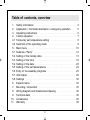
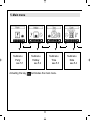
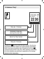
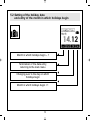
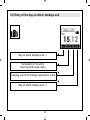
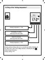
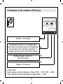
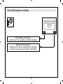
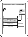
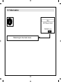
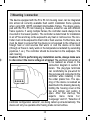
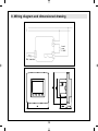
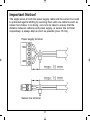
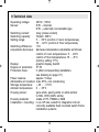
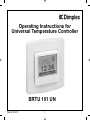
Operating Instructions for
Universal Temperature Controller
BRTU 101 UN
Stand 11.2011
1
2
Table of contents, overview
11.
12.
13.
14.
14.1
14.2
15.
15.1
15.2
15.3
15.4
15.5
15.6
15.7
15.8
16.
17.
18.
19.
10.
11.
Safety information . . . . . . . . . . . . . . . . . . . . . . . . . . . . . . . . . . . . . . . . . . . . . .
Application / functional description / emergency operation . . . . .
Operating instructions . . . . . . . . . . . . . . . . . . . . . . . . . . . . . . . . . . . . . . . . . .
Control operation . . . . . . . . . . . . . . . . . . . . . . . . . . . . . . . . . . . . . . . . . . . . . . .
Temporary set temperature setting . . . . . . . . . . . . . . . . . . . . . . . . . . . . .
Selection of the operating mode . . . . . . . . . . . . . . . . . . . . . . . . . . . . . . .
Main menu . . . . . . . . . . . . . . . . . . . . . . . . . . . . . . . . . . . . . . . . . . . . . . . . . . . . . .
Submenu “Party” . . . . . . . . . . . . . . . . . . . . . . . . . . . . . . . . . . . . . . . . . . . . . . . .
Setting of the holiday data . . . . . . . . . . . . . . . . . . . . . . . . . . . . . . . . . . . . . .
Setting of the time . . . . . . . . . . . . . . . . . . . . . . . . . . . . . . . . . . . . . . . . . . . . . .
Setting of the date . . . . . . . . . . . . . . . . . . . . . . . . . . . . . . . . . . . . . . . . . . . . . .
Setting of the set temperatures . . . . . . . . . . . . . . . . . . . . . . . . . . . . . . . .
Entry of the weekday programs . . . . . . . . . . . . . . . . . . . . . . . . . . . . . . . .
Information . . . . . . . . . . . . . . . . . . . . . . . . . . . . . . . . . . . . . . . . . . . . . . . . . . . . . .
Settings . . . . . . . . . . . . . . . . . . . . . . . . . . . . . . . . . . . . . . . . . . . . . . . . . . . . . . . . .
Experts menu . . . . . . . . . . . . . . . . . . . . . . . . . . . . . . . . . . . . . . . . . . . . . . . . . . .
Mounting / connection . . . . . . . . . . . . . . . . . . . . . . . . . . . . . . . . . . . . . . . . . .
Wiring diagram and dimensioned drawing . . . . . . . . . . . . . . . . . . . . .
Technical data . . . . . . . . . . . . . . . . . . . . . . . . . . . . . . . . . . . . . . . . . . . . . . . . . .
Accessories . . . . . . . . . . . . . . . . . . . . . . . . . . . . . . . . . . . . . . . . . . . . . . . . . . . . .
Warranty . . . . . . . . . . . . . . . . . . . . . . . . . . . . . . . . . . . . . . . . . . . . . . . . . . . . . . . .
3
04
05
06
07
08
09
10
12
13
18
20
23
25
29
30
33
35
36
38
39
39
1. Safety information
Expert electricians only may open this device in due compliance with the
wiring diagram shown in the housing cover / on the housing / represented in
the corresponding operating instructions. All expert electricians charged
with the execution of such works must comply with the relevant safety regulations currently operative and in force. Caution: The operation of the controller in the vicinity of other devices that do not comply with the EMC directives may affect its functions. The company charged with the installation of
the device must, after the completion of the installation works, instruct the
user of the control system into its functions and in how to operate it correctly.
These operating instructions must be kept at a place that can be accessed
freely by the operating and/or servicing personnel in charge.
4
2. Application / functional description / emergency operation
The controller described in these instructions is provided for flush installation and has been specially devised for the time-dependent control of the
temperatures in individual rooms or of the temperatures produced by electric or warm-water heating systems (systems with normally closed valve
actuators). The device can be used as floor or as room temperature controller
with additional floor temperature controller function. Operation in emergency
mode is triggered if the internal or external sensor is defective. The same
applies if no sensor has been connected when using the device as room
temperature controller with additional floor monitoring function and also
when using it as floor temperature controller. An error message appears on
the display and an indicator lamp starts blinking red to indicate this condition. During operation in emergency mode a fixed 30% duty cycle is being
maintained to prevent the related room from cooling down thoroughly and
protect it against frost damage. The activation time divides into a 3-minute
ACTIVE and a 7-minute OFF time.
5
3. Operating instructions
0
The device is equipped with 4 touch keys, all of which have been marked by
the symbol . The functions allocated to them may vary in dependence on
the operation requirements. The related function is being indicated on the
display which exists above the corresponding keys. A special protective
function helps prevent an inadvertent activation of the touch keys. This
function is activated 20 seconds after any of the touch keys has last been
activated. Actuating any of the touch keys deactivates this function again for
2 seconds.
6
4. Control operation
Temporary set temperature setting
see 4.1
▼
Selection of the operating mode
see 4.2
▼
Main menu
see 5.
▼
7
▼
Temporary set temperature setting
see 4.1
4.1 Temporary set temperature setting
▼
Set temperature – 0.5 K
▼
Acquisition of the values
Return to normal control mode
▼
Set temperature + 0.5 K
If no key has been activated within a period of approx. 5 seconds, the
system returns to normal control mode again. The changed temperature
value is being taken over and imported. The adjusted set temperature continues to be effective until the moment the operating mode is changed, no
matter if changing manually or automatically after triggering by the switch
clock.
8
▼
▼
▼
▼
▼
▼
4.2 Selection of the operating mode
▼
▼
Actuating the touch key “Mode” allows to change the operating mode
in the order shown below:
– Automatic mode (in compliance with the related weekday mode settings)
– Comfort mode, permanently
– ECO mode, permanently
– Operating mode “OFF”
In “OFF” mode, the controller activates the heating when underrunning a
temperature level of approx. 5°C and deactivates the operations when
exceeding a temperature level of approx. 6°C. This antifreezing function
helps prevent rooms from cooling down thoroughly and protects against the
occurrence of frost damage.
9
5. Main menu
▼
▼
Submenu
Party
see 5.1
Actuating the key
▼
▼
▼
▼
▼
▼
Submenu
Holiday
see 5.2
Submenu
Time
see 5.3
terminates the main menu.
10
▼
▼
▼
Submenu
Date
see 5.4
5. Main menu
▼
▼
▼
Submenu
“temperature”
see 5.5
▼
▼
▼
▼
▼
▼
Submenu
“weekday
programs”
see 5.6
Info function
see 5.7
▼
▼
Submenu
“settings”
see 5.8
▼
Calling of the
experts menu
see 6.
11
5.1 Submenu “Party”
▼
Party end – 15 minutes
▼
Start of the “Party” function
▼
Termination of data entry,
returning to the main menu
▼
Party end + 15 minutes
Actuating the
touch key starts the party function. Once the preadjusted time has been attained, the system switches automatically
back to the previous operating mode. Actuating the touch key
cancels the party function at any time. While operating in party mode,
all control operations are performed in dependence on the actually
adjusted comfort temperature.
12
5.2 Setting of the holiday data
and entry of the month in which holidays begin
Month in which holidays begin – 1
▼
Termination of the data entry,
returning to the main menu
▼
Changing over to the day on which
holidays begin
▼
▼
Month in which holidays begin + 1
13
5.2 Entry of the day on which holidays begin
Day on which holidays begin – 1
▼
Termination of the entry,
returning to the main menu
▼
Changing over to the month in which
holidays end
▼
▼
Day on which holidays begin + 1
14
5.2 Entry of the day on which holidays end
Day on which holidays end – 1
▼
Termination of the entry,
returning to the main menu
▼
▼
Changing over to the day on which holidays end
▼
Day on which holidays end + 1
15
5.2 Entry of the day on which holidays end
Day on which holidays end – 1
▼
Termination of the entry,
returning to the main menu
▼
▼
Changing over to the holidays temperature menu
▼
Day on which holidays end + 1
16
5.2 Entry of the “holiday temperature”
Holiday temperature – 0.5 K
▼
Termination of entries,
returning to the main menu
▼
Import of all values,
returning to the main menu
▼
▼
Holiday temperature + 0.5 K
Already existing holiday data can be cancelled by simply changing, via
the main menu, over to the holiday submenu. Actuating the key
allows to leave this menu.
Factory setting: 17°C
17
5.3 Setting of the time
Entry of hours
▼
Hour – 1
Termination of entries,
returning to the main menu
▼
Import of the selected value,
changing to the minute entry display
▼
▼
Hour + 1
18
5.3 Entry of minutes
▼
Minute – 1
Termination of entries,
returning to the main menu
▼
Import of the selected value,
returning to the main menu
▼
▼
Minute + 1
Actuating the
key after a change of the minutes, allows to reset
the seconds entry to “0”.
19
5.4 Setting of the date
Entry of the year
▼
Year –1
Termination of entries,
returning to the main menu
▼
Import of the selected value,
changing to the month entry display
▼
▼
Year + 1
20
5.4 Entry of the month
▼
Month – 1
Termination of entries,
returning to the main menu
▼
Import of the selected value,
changing to the day entry display
▼
▼
Month + 1
21
5.4 Entry of the day
▼
Day – 1
Termination of entries,
returning to the main menu
▼
Import of the selected value,
returning to the main menu
▼
▼
Day + 1
22
5.5 Setting of the set temperatures
Entry of the comfort temperature
Comfort temperature – 0.5 K
▼
Termination of entries,
returning to the main menu
▼
Import of the selected value,
changing to the ECO temperature entry display
▼
▼
Comfort temperature + 0.5 K
If using the device as floor temperature controller, the desired floor temperature can be set using this menu. The same applies in regard to the
setting of the desired room temperature when using it as room temperature controller.
Factory setting: 20°C
23
5.5 Entry of the ECO temperature
ECO temperature – 0.5 K
▼
Termination of entries,
returning to the main menu
▼
Import of the selected value,
returning to the main menu
▼
▼
ECO temperature + 0.5 K
The maximum adjustable ECO temperature value corresponds to
the comfort temperature value – 1K.
Factory setting: 17°C
24
5.6 Entry of the weekday programs
Selection of the weekday
▼
Weekday backward
Termination of entries,
returning to the main menu
▼
Changing to the display for the entry
of comfort and ECO times
▼
▼
Weekday onward
25
5.6 Selection of the comfort or ECO times
▼
Position – 15 minutes
▼
Shifting between comfort or
ECO time period
▼
Termination of entries. If no changes have
been made, the system returns to the display for
the selection of the weekday. Otherwise, it
changes over to the entry confirmation display.
▼
Position + 15 minutes
Comfort times:
Factory settings valid from Monday to Friday: 05:00 … 9:00 / 16:00 … 22:00
Factory settings valid from Saturday to Sunday: 06:00 … 22:00
26
5.6 Confirmation of entries
Termination of entries,
returning to the weekday selection display
▼
Storing of the entries
Change to the menu enabling the copying
of entries with respect to other weekdays
▼
27
5.6 Import of the entries made with regard to other weekdays
▼
Selection backward
No import of entries,
returning to the weekday selection display
▼
Import of entries with respect to the
selected weekday(s).
▼
▼
Selection forward
28
5.7 Information
29
▼
Returning to the main menu
5.8 Settings
▼
Selection downward
Termination of entries,
returning to the main menu
▼
Activation or deactivation of the
selected function
▼
▼
Selection upward
30
5.8 Settings
The following functions are available:
1.Keylock
The keylock is activated 2 minutes after actuating any of the touch keys. The
key icon appears on the display to indicate this locked state. The touch keys
can be reactivated by actuating and holding any of the keys depressed for
10 seconds.
2. Automatic change between daylight saving and standard time
The harmonised daylight saving time in the European Union takes effect as
of the last Sunday in March, i.e. as of 2.00 o’clock a.m. CET and lasts until
to 3.00 o’clock a.m. on the last Sunday in October (CEST) each year (directive 2000/84/EG of the European Council and Parliament). The temperature
controller changes the time all automatically at these dates. The automatic
change between daylight saving and standard time can also be deactivated
to enable the changing of the time at other dates or to meet the time conditions in other regions.
3. Valve and pump protection function
The valve and pump protection function serves to prevent the valve seat
and/or the pump(s) from corroding up during longer stop times. If using the
device for the control of warm-water heating systems, activating the valve
protection function is recommended. After activation of the valve and pump
protection function, the controller actuates the valve(s) or triggers a heating
pump every Monday at 11.00 o’clock a.m. over a 5 minute time period. The
31
valve and pump protection function is rendered active only if no heating
operations were executed within the last week. Unnecessary heating during
the heating season is thus avoided, thereby leaving the control system unaffected.
4. Self-learning function
The self-learning function serves for the autonomous attaining of the comfort
temperature at a preset time. The antedated point at which the system switches from ECO over to comfort temperature sets itself all autonomously.
Depending on the calorific output and the prevailing outside temperature, the
heating time will vary.
5. Backlighting of the display
The length of time during which the display backlight is on, can be selected
as follows:
1. Backlight during operation plus 10 seconds after the last actuation of any
of the touch keys;
2. Additional backlight during operating times in comfort and also in party
mode;
3. Permanent backlight.
6. Display indications
If configuring the device for use as floor temperature controller, only the time
indication is active.
If the HTRRUu 210.021 has not been configured for use as floor temperature
controller, the operator can select between the following indications:
1. Time;
2. Temperature;
3. Time & temperature (alternating).
32
6. Experts menu
Depressing the right touch key and keeping it depressed for 10 seconds after
accessing the “settings” submenu (see page 11) from the main menu, enables to
call the experts menu.
Caution! This menu enables to make control settings that may only be performed by a qualified heating specialist or an expert electrician. The settings made
while operating in this mode cannot be reset via the reset function and have to
be made knowingly, therefore. Clear proof that such settings have been made by
one person only is thus ensured.
The following settings are available:
1. Selection of controller configuragtion variants
The following controller configuration variants can be selected: “Room temperature controller”, “Room temperature controller with floor temperature controller
function” or “Floor temperature controller”.
2. Language
The operator can select between the following languages: Czech, Dutch, English,
French, German Polish and Russian.
3. Measuring correction
The measured temperature value can, in dependence on the related configuration, be adjusted with regard to each individual sensor within a range from -5 K to
+5 K at 0.1 K steps. At the same time, the uncorrected value measured by the related sensor is being indicated on the display (factory setting 0.0).
4. Maximum temperature(setting possible only when using the device as room
temperature controller with floor temperature controller function or as floor temperature controller)
33
The maximum temperature measured by the floor temperature can be defined
within a range from 15 to 42°C. Damages to the floor in consequence of excessive temperatures can thus be prevented (factory setting 42°C).
5. Entry of the connected load (entry possible only when using the device as
room temperature controller with floor temperature controller function or as floor
temperature controller)
In order to allow to compensate the self heating of the HTRRUu, the power consumption of the connected consumer needs to be entered. The power consumed
in consequence of the connected heating load is indicated in kW and can be
adjusted within a range from 0.1 to 2.3. With intermediate values, the nearest
lower value needs to be set. If actuating valves instead of controlling an electric
heating system, the low power consumption of these valves can be neglected,
so that no changes need to be made (factory setting 0.1).
6. Control methods (available only when using the device as room temperature
controller with floor temperature controller function or as floor temperature controller)
PI-PWM method (proportional–integral), recommended for the control of warmwater and floor heating systems.
Two-point method (hysteresis), recommended for the control of electric direct or
storage heating systems (factory setting: two-point method).
7. External sensor (connection possible only when using the device as room
temperature controller with floor temperature controller function or as floor temperature controller)
The HTRRUu210.021 allows to connect external temperature sensors (NTC) with
resistance values of 2, 12, 15 or 33 kΩ. The actually used temperature sensor
needs to be selected here (factory setting 2 kΩ).
8. Reset function
Actuating this function resets all settings made outside of the experts menu
(except for time and date) to the condition as delivered.
34
7. Mounting / connection
The device equipped with the 50 x 50 mm housing cover can be integrated
into almost all currently available flush switch installation frame systems
when using DIN 49075 compliant intermediate frames. The device equipped with the 55 x 55 mm housing is, likewise, suited for use with different
frame systems. If using multiple frames, the controller needs always to be
mounted in the lowest position. The controller is determined for installation
in an UP box and may not be exposed to any heat or cold sources. The controller must not be exposed to direct cold or heat sources. Furthermore, care
must be taken to ensure that the device is not exposed to the influence of
foreign heat or cold sources that warm or cool the device at its back
(through air flows in cavity walls or the temperatures radiated by ascending
pipelines, f. ex.). The controller should be mounted on the wallpaper / the
wall covering.
Caution: Prior to performing any installation works, always make sure
to disconnect the mains voltage at all poles! The electrical connection is
to be realised as shown in the
connection diagram in section 8
herein. The plug-type terminals
can comfortably be pre-wired for
this purpose and connected to the
controller while installing it into
the under plaster box. The opening of the device is realised as
described in the drawing below by
holding the housing cover at the
top and bottom and pulling it
open. After first start-up, the
experts
menu
items
6.2,
“Language” and 6.1, “Selection of
controller configuration variants”, are being called up all automatically. The
device will only be operable after having made correct entries.
35
8. Wiring diagram and dimensioned drawing
Load:
max.
2.3kW
Ext. sensor
36
Important Notice!
The single wires of both the power supply cable and the sensor line need
to protected against shifting by securing them with one cable tie each as
shown here below. In so doing, care is to be taken to ensure that the
distance between cable tie and power supply- or sensor line terminal
respectively, is always kept as short as possible (max. 15 mm).
Power supply terminal
Sensor line terminal
37
9.Technical data
Operating voltage:
Sensor:
230 V~, 50 Hz
NTC – internal;
NTC – externally connectable type
Switching contact:
relay (make contact)
Switching capacity:
10(2)A / 230 V~
Setting range:
5 … 30°C (control of room temperatures);
10 … 42°C (control of floor temperature)
Switching difference:
<1K
emperature decrease: decrease temperature adjustable as follows:
control of room temperatures: 5 … 29°C
control of floor temperatures: 10 … 41°C
(factory setting 17°C)
Display:
graphic display, backlit
Degree of protection: IP 30
Protection class:
II (after corresponding installation,
see drawing on page 37)
Power reserve:
approx. 5 days
Admissible air moisture: max. 95%, non condensing
Storage temperature:
– 20 … + 70°C
Ambient temperature: 0 … 35°C
Housing colour:
pure white, pearly white or white similar
to RAL 9016 (traffic white)
Housing material:
made of PC, PMMA or ABS
Installation / mounting: in an UP box; suited for integration into all
currently available flush mounted switch frame
installation systems
38
10. Accessories
HF-8/4-K2 – External floor temperature sensor, incl. 4 m long cable
HF-8/6-K2 – External floor temperature sensor, incl. 6 m long cable
THF – Sleeve to ensure the sensor is protected when installing it into the
floor screed
11. Warranty
The technical data specified herein have been determined under laboratory
conditions and in compliance with generally approved test regulations, in
particular DIN standards. Technical characteristics can only be warranted to
this extent. The testing with regard to the qualification and suitability for the
client’s intended application or the use under service conditions shall be the
client’s own duty. We refuse to grant any warranty with regard thereto.
Subject to change without notice.
39
Glen Dimplex Deutschland GmbH
Am Goldenen Feld 18
D-95326 Kulmbach
Email: [email protected]
Phone: +49 (0)9221 709-564
Fax:
+49 (0)9221 709-589
Internet: www.dimplex.de/en
Note on Disposal!
Do not dispose of the unit
with general household waste.
The device must be taken to a
local waste disposal.
40