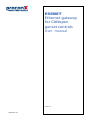
1
ESENET
Ethernet gateway
for CANopen
genset controls
User manual
Edition 2.0
UMESENET-1301
ESENET
Ethernet gateway for CANopen genset controls: User manual
Copyright © 2011 proconX Pty Ltd. All rights reserved.
Document revision history
2011-01-28
Initial Release
2011-04-06
Editorial Changes.
2013-02-19
Added LS-5 configuration and Easygen-1000 Modbus table
No part of this material may be reproduced or transmitted in any form or by any means or used to make any derivative work without
express written consent from the copyright holders.
proconX is a trademark of proconX Pty Ltd. Modbus is a registered trademark of Schneider Automation Inc. CANopen is a registered
trademark of CAN in Automation e.V. Easygen is a trademark of Woodward, Inc. All other product and brand names mentioned in this
document may be trademarks or registered trademarks of their respective owners.
Disclaimer
proconX Pty Ltd makes no warranty for the use of its products, other than those expressly contained in the Company’s standard warranty
which is detailed in the Terms and Conditions located on the Company’s Website. The Company assumes no responsibility for any errors
which may appear in this document, reserves the right to change devices or specifications detailed herein at any time without notice,
and does not make any commitment to update the information contained herein. No licenses to patents or other intellectual property
of proconX are granted by the Company in connection with the sale of proconX products, expressly or by implication. proconX products
are not authorized for use as critical components in life support devices or systems.
Support & product feedback
We provide an electronic support and feedback system for our proconX products. It can be accessed through the following web link:
http://www.proconx.com/support
Your feedback and comments are always welcome. It helps improving this product.
Contact
For further information about the ESENET product or this document please contact us at:
proconX Pty Ltd
Unit 7 / 14 Argon St
Sumner QLD 4074
Australia
Tel +61 7 3376 3911
Fax +61 7 3102 9206
Website: http://www.proconx.com/esenet
Contents
Important user information ....................................................................................... vii
Safety Precautions .............................................................................................. vii
Document conventions ..................................................................................... viii
1 Introduction ............................................................................................................. 1
Features ............................................................................................................... 2
Quick start checklist ............................................................................................ 3
2 Description .............................................................................................................. 5
LED indicators ..................................................................................................... 5
Principles of operation ........................................................................................ 7
3 Installation ............................................................................................................... 9
Regulatory notes ................................................................................................. 9
Unpacking, handling and storage ....................................................................... 9
Before connecting anything ................................................................................ 9
DIN rail mounting and removal ......................................................................... 10
Mounting rules .................................................................................................. 10
Powering the ESENET ........................................................................................ 11
Wiring the CAN interface .................................................................................. 11
Connecting Ethernet ......................................................................................... 12
Connecting to the diagnostic port .................................................................... 12
4 Ethernet & IP configuration ................................................................................... 15
IP setup using a web browser and a cross-over network cable .......................... 15
IP setup using a terminal program like HyperTerminal ....................................... 16
Temporarily changing the IP settings on your PC .............................................. 17
5 Web browser based management ......................................................................... 19
Connecting to the ESENET ................................................................................ 19
Monitoring and diagnostic ................................................................................ 20
Device status .............................................................................................. 20
Modbus connection status ........................................................................ 21
CAN communication status ....................................................................... 22
Finding the firmware version and serial number ........................................ 23
Configuring and commissioning ........................................................................ 24
Configuring Ethernet and IP ...................................................................... 24
Configuring CAN and CANopen ................................................................. 25
Remote restarting the device ..................................................................... 25
6 Running Toolkit via the ESENET gateway ............................................................... 27
How it works .................................................................................................... 27
Installation ......................................................................................................... 28
Running Toolkit ................................................................................................. 30
TCP Ports ........................................................................................................... 32
7 Configuration of connected Woodward controls ................................................... 33
Specific information for Easygen-3000 series controls ....................................... 34
CAN interface ............................................................................................ 35
Transmit PDOs ........................................................................................... 35
Specific information for LS-5 controls ............................................................... 36
CAN interface ............................................................................................ 37
Transmit PDOs ........................................................................................... 37
Specific information for DTSC-200 controls ....................................................... 38
CAN interfaces ........................................................................................... 39
UMESENET-1301
iii
Transmit PDOs ...........................................................................................
8 Modbus data reference .........................................................................................
Modbus Slave IDs ..............................................................................................
Visualisation Data Table .....................................................................................
Easygen-3000 .............................................................................................
LS-5 ............................................................................................................
DTSC-200 ...................................................................................................
Easygen-1000 .............................................................................................
Modbus function codes ....................................................................................
Modbus exception codes ...................................................................................
9 Decommissioning ...................................................................................................
Disconnecting ....................................................................................................
Disposal .............................................................................................................
A Specifications ........................................................................................................
Dimensions ........................................................................................................
Glossary ....................................................................................................................
Index .........................................................................................................................
40
43
43
44
45
45
45
46
47
48
49
49
49
51
52
53
55
Figures
2.1 Location of connectors ......................................................................................... 5
2.2 Gateway operation ............................................................................................... 7
5.1 Device management and configuration via the web browser ............................. 19
5.2 Overview page .................................................................................................... 20
5.3 Modbus status page ........................................................................................... 21
5.4 CAN communication status page ....................................................................... 22
5.5 About page ........................................................................................................ 23
5.6 Ethernet and IP settings page ............................................................................ 24
5.7 IP settings changed confirmation ....................................................................... 25
5.8 Restart device page ............................................................................................ 25
5.9 Restart confirmation page .................................................................................. 26
6.1 Toolkit network selection .................................................................................... 30
6.2 Entering the ESENET gateway’s IP address in Toolkit .......................................... 31
6.3 Successful CAN over TCP/IP connection .............................................................. 31
6.4 Example of Toolkit indicating a communication error ......................................... 32
7.1 "Configure interfaces" menu in Woodward Toolkit .............................................. 34
7.2 "Configure CAN interface 1" menu in Woodward Toolkit ..................................... 35
7.3 "Transmit PDOs" menu in Woodward Toolkit ....................................................... 36
7.4 "Interfaces config" menu in Woodward Toolkit ................................................... 37
7.5 "CAN interface 1 config" menu in Woodward Toolkit .......................................... 37
7.6 "Transmit PDOs" menu in Woodward Toolkit ....................................................... 38
7.7 Parametrize dialog in LeoPC software ................................................................ 39
7.8 DTSC-200 CAN interfaces section in "Parametrize" dialog of LeoPC software....... 39
7.9 TPDO section in "Parametrize" dialog of Woodward’s LeoPC software ................. 41
8.1 Modbus data table structure .............................................................................. 43
8.2 Message sequence chart for visualiation data .................................................... 44
A.1 Enclosure dimensions ......................................................................................... 52
iv
UMESENET-1301
Tables
2.1
3.1
3.2
3.3
3.4
7.1
7.2
8.1
8.2
8.3
8.4
8.5
8.6
8.7
UMESENET-1301
LED diagnostic codes ............................................................................................ 6
Power supply connector pinout .......................................................................... 11
CAN connector pinout ........................................................................................ 11
Ethernet connector pinout ................................................................................. 12
Diagnostic port connector pinout ....................................................................... 13
Modbus Slave ID, CANopen Node-ID & COB-ID relationships .............................. 33
Supported Data Protocols ................................................................................... 34
Modbus Slave ID and CANopen Node-ID relationship ......................................... 43
Modbus register addresses for Easygen-3000 series visualisation data ................ 45
Modbus register addresses for LS-5 series visualisation data ............................... 45
Modbus register addresses for DTSC-200 visualisation data ................................ 45
Modbus register addresses for Easygen-1000 series visualisation data ................ 46
Supported Modbus function codes .................................................................... 47
Modbus exception codes .................................................................................... 48
v
This page intentionally left blank
vi
UMESENET-1301
Important user information
Important user information
This manual explains how to install, operate and configure a ESENET. This device may
only be used for the applications described in this document.
This manual is to be used with a ESENET with firmware version 2.1.
These instructions are intended for use by trained specialists in electrical installation
and control and automation engineering, who are familiar with the applicable national
standards and safety procedures.
Safety Precautions
ELECTRICAL HAZARD
• This equipment must be installed and serviced only by qualified personnel. Such
work should be performed only after reading this entire set of instructions.
• Before performing visual inspections, tests, or maintenance on this equipment,
disconnect all sources of electric power. Assume that all circuits are live until they
have been completely de-energized, tested, and tagged. Pay particular attention
to the design of the power system. Consider all sources of power, including the
possibility of backfeeding.
• Apply appropriate personal protective equipment and follow safe electrical
practices.
• Turn off all power supplying the equipment in which the ESENET is to be installed
before installing, wiring or removing the ESENET.
• Always use a properly rated voltage sensing device to confirm that power is off.
• The successful operation of this equipment depends upon proper handling,
installation, and operation. Neglecting fundamental installation requirements
may lead to personal injury as well as damage to electrical equipment or other
property.
Failure to follow these instructions could result in death or serious injury!
UMESENET-1301
vii
Document conventions
Throughout this manual we use the following symbols and typefaces to make you aware
of safety or other important considerations:
Indicates a potentially hazardous situation that, if not avoided, could result in death or serious injury.
Indicates a potentially hazardous situation that, if not avoided, could result in damage to equipment.
Indicates information that is critical for successful application
and understanding of the product.
Provides other helpful user information that does not fall in
above categories.
Provides supplemental user information.
viii
Acronym
This typeface is used to introduce acronyms or product
names.
Command
This typeface is used to represent commands, prompts, input
fields and filenames. In the context of programming it is used
for functions, variable names, constants or class names.
Placeholder
This typeface is used to represent replacable text. Replaceable
text is a placeholder for data you have to provide, like filenames or command line arguments.
User input
This typeface is used to represent data entered by the user
or buttons.
Screen output
Screen output or program listing
UMESENET-1301
Introduction
Chapter 1. Introduction
The ESENET is an Ethernet gateway specifically designed to interface Woodward’s
Easygen series genset controls with Modbus/TCP networks and Toolkit. It interfaces via
CAN bus with the Woodward controls.
The ESENET takes advantage of the multi-master capability and fast transmission speed
of CAN to offer short Modbus/TCP poll cycles as well as concurrent access.
A single ESENET added to the CAN network will make all Visualisation Data of connected
Woodward CANopen controls available without adding additional load to the CAN bus
communication. In addition concurrent and fast read and write access to Parameter IDs
is possible utilising parallel CANopen SDO transfers.
In addition to Modbus/TCP access the ESENET provides a Toolkit interface. Using this
facility you can run local and remote Toolkit sessions from your PC via Ethernet and
TCP/IP through the ESENET gateway to Woodward controls connected on ESENET's CAN
interface.
Usage and configuration of the gateway is simple and conveniently performed using a
web browser which connects to the embedded web server.
Common applications include:
• PLC connection
• Operator panel interfacing
• HMIs
UMESENET-1301
1
• SCADA integration
• Power station automation
• Gen set control
• Remote control & monitoring
• Data logging
Features
The ESENET gateway provides the following key features:
• Multiple concurrent Modbus/TCP connections
• Toolkit interface to configure Woodward controls via Ethernet
• Supports Easygen 3500, 3400, 3200, 3100, 2000 and 1000 models
• Supports LS-5
• Supports DTSC-200
• Addresses up to 16 controls
• Uses existing CAN wiring
• Fast Modbus poll rates for Visualisation Data (< 7 ms)
• Concurrent reads and writes of Parameter IDs
• Register layout and address range compatible with serial Modbus data protocol 5003
for Easygen-3000 devices
• Internal buffer for Visualisation Data
• Supports alternative Modbus register range below address 50000
• Transparent handling of data guarantees future compatibility
• Low configuration overhead, just an IP address
• Embedded web server for easy configuration and commissioning using a web browser
• Firmware upgradeable via Ethernet
• Status LEDs for power, Ethernet link, device status and communication status
• DIN rail mountable
• 24 V DC (10-30 V) power supply
2
UMESENET-1301
Introduction
Quick start checklist
• Read this set of instructions properly and in its entirety.
• Mount the unit.
• Connect the power. Do not connect yet CAN bus or serial ports.
• Configure the Ethernet communications settings with a web browser (using an
Ethernet crossover cable) or with a terminal program like HyperTerminal (using a null
modem cable)
• Configure the CAN bus settings.
• Configure the serial line communication settings.
• Configure the operational aspects of the device.
• Wire CAN bus.
• Wire serial line interfaces.
UMESENET-1301
3
This page intentionally left blank
4
UMESENET-1301
Description
Chapter 2. Description
The power and CAN terminals are placed on the top side of the unit. The RS-232 and
Ethernet connectors are placed on the bottom side of the unit as shown in the following
illustration:
TOP VIEW
BOTTOM VIEW
FRONT VIEW
Figure 2.1: Location of connectors
Clear front cover
Diagnostic port connector
Ethernet connector
DIN rail clip
Power LED
Ethernet link LED
Device status LED
Communication status LED
Power terminals
CAN connector
LED indicators
Four LEDs located at the front panel indicate the status of the ESENET. The LEDs assist
maintenance personnel in quickly identifying wiring or communication errors.
A LED test is exercised at power-up, cycling each LED off, green and then red for
approximately 0.25 seconds. At the same time the power-on self test of the device is
performed.
UMESENET-1301
5
The following table outlines the indicator condition and the corresponding status after
the power-on self test has been completed:
LED
Function
Condition
Indication
Power
Power
Off
No power applied to the device.
Green
Power supply OK
Off
No Ethernet link
Green
Ethernet link OK
Off
The device has an unrecoverable fault; may need replacing.
Flashing green at 1 s
rate
Device operational but needs commissioning due to configuration
missing, incomplete or incorrect.
Green
The device is operating in normal condition.
Link
Ethernet link
Status1
Device status
Flashing red at 1 s rate Device operational but has a fault listed which requires acknowledgment.
Red
The device has an unrecoverable fault; may need replacing. Flashing
sequence and rate of Status2 LED indicates fault class.
Table 2.1: LED diagnostic codes
6
UMESENET-1301
Description
Principles of operation
The ESENET acts as a CANopen consumer and monitors the CAN bus for transmission
of well-known communciation objects. Once these communication objects identify
one of the supported Woodward controls, the ESENET starts to buffer all multiplexed
visualisation data of such device into its internal data tables.
The ESENET also acts as a Modbus server on the Ethernet interface. It accepts connections
and Modbus queries from Modbus master devices. The Modbus registers are then served
from the ESENET's internal data tables. Because of the data table buffering, the Modbus
can be polled independant of CANopen TXPDO transfer cycles. The ESENET allows a
maximum of 8 connections via Modbus/TCP.
CANopen
MODBUS/TCP
Read Input Registers
Write Single Register
Read Holding Register
PLC
TCP/IP
TCP/C
A Nop
OB
en-SD
ridge
Visualisation
Data Table
Configuration &
Remote Control
Toolkit
Interface
SD
O
SD
O
ESENET
gateway
PC running WoodwardToolkit
Figure 2.2: Gateway operation
UMESENET-1301
7
This page intentionally left blank
8
UMESENET-1301
Installation
Chapter 3. Installation
Regulatory notes
1. The ESENET is suitable for use in non-hazardous locations only.
2. The ESENET is not authorized for use in life support devices or systems.
3. Wiring and installation must be in accordance with applicable electrical codes in
accordance with the authority having jurisdiction.
4. This is a Class A device and intended for commercial or industrial use. This equipment
may cause radio interference if used in a residential area; in this case it is the
operator’s responsibility to take appropriate measures.
5. The precondition for compliance with EMC limit values is strict adherence to the
guidelines specified in this set of instructions. This applies in particular to the area
of grounding and shielding of cables.
FCC Notice (USA only)
This equipment has been tested and found to comply with the limits for a Class A
digital device, pursuant to Part 15 of the FCC Rules. These limits are designed to provide
reasonable protection against harmful interference when the equipment is operated
in a commercial environment. This equipment generates, uses, and can radiate radio
frequency energy and, if not installed and used in accordance with the instruction
manual, may cause harmful interference to radio communications. Operation of this
equipment in a residential area is likely to cause harmful interference in which case the
user will be required to correct the interference at his own expense.
Industry Canada Notice (Canada only)
This Class A digital apparatus complies with Canadian ICES-003.
Unpacking, handling and storage
1. Please read this set of instructions. carefully before fitting it into your system.
2. Keep all original packaging material for future storage or warranty shipments of the
unit.
3. Do not exceed the specified temperatures.
Before connecting anything
1. Before installing or removing the unit or any connector, ensure that the system power
and external supplies have been turned off.
2. Check the system supply voltage with a multimeter for correct voltage range and
polarity.
UMESENET-1301
9
3. Connect the power supply cable and switch on the system power. Check if the Power
LED is lit.
4. Turn off system power.
5. Connect all I/O cables.
6. Once you are certain that all connections have been made properly, restore the
power.
DIN rail mounting and removal
The ESENET gateway is designed to be mounted on a 35 mm DIN rail according to DIN/
EN 50022. The enclosure features a 35 mm profile at the back which snaps into the DIN
rail. No tools are required for mounting. Please observe the rules outlined in the section
called “Mounting rules”.
To mount the unit on a DIN rail, slot the top part of the
ESENET into the upper guide of the rail and lower the enclosure until the bottom of the red hook clicks into place.
1
Click
2
To remove the ESENET from the DIN rail, use a screw driver
as a lever by inserting it in the small slot of the red hook
and push the red hook downwards. Then remove the unit
from the rail by raising the bottom front edge of the enclosure.
2
1
Mounting rules
The enclosure provides protection against solid objects according to IP 20 / NEMA Type 1
protection rating. When mounting the unit observe the following rules:
• No water splash and water drops
• No aggressive gas, steam or liquids
• Avoid dusty environments.
• Avoid shock or vibration
10
UMESENET-1301
Installation
• Do not exceed the specified operational temperatures and humidity range.
• Mount inside an electrical switchboard or control cabinet.
• Make sure there is sufficient air ventilation and clearance to other devices mounted
next to the unit.
• Observe applicable local regulations like EN60204 / VDE0113.
Powering the ESENET
Before connecting power please follow the rules in the section called “Safety Precautions” and the section called “Before connecting anything”.
V+
V-
Power is supplied via a 3.81 mm 2-pin pluggable terminal block located at the top side
of the mounted unit (refer to Figure 2.1, “Location of connectors”). The following table
and picture shows the power terminal socket pinout:
Pin
Signal
1
V+
2
V-
Function
Positive voltage supply (10 - 30 V DC)
Negative voltage supply, DC power return
Table 3.1: Power supply connector pinout
Make sure that the polarity of the supply voltage is correct before connecting any
device to the serial and CAN ports! A wrong polarity can cause high currents on the
ground plane between the V- power supply pin and the CAN port and serial port
ground pins, which can cause damage to the device.
Wiring the CAN interface
The CAN interface connects the ESENET to the Woodward CANopen based controls.
CAN_L
GND
The CAN connector is a male 9-pin D-sub type located at the top side of the mounted
unit (refer to Figure 2.1, “Location of connectors”). It has industry standard CiA DS-102
pinout as shown in the following table and picture:
1
GND
CAN_H
6
Pin
Signal
1
NC
2
CAN_L
3
CAN_GND
4
NC
5
NC
6
CAN_GND
7
CAN_H
8
NC
9
NC
Function
CAN_L bus line
CAN ground
CAN ground
CAN_H bus line
Table 3.2: CAN connector pinout
UMESENET-1301
11
• The network must be terminated at both ends with its characteristic impedance,
typically a 120 Ohm 1/4 W resistor.
1
• Maximum number of electrically connected CAN nodes is 64 .
• Maximum CAN cable length is 250 m (820 ft) and is derated depending on bit rates
and cable type.
• Stub connections off the main line should be avoided if possible or at least be kept as
short as possible. Stub connections must not have terminating resistors.
• To ensure a high degree of electromagnetic compatibility and surge protection the
cable should be twisted pairs and shielded. An additional cable conductor or pair may
be used for the CAN_GND reference.
Do not connect the cable shield to the CAN_GND pins or the connector shell! Use
an external chassis ground connection to terminate the shield.
Connecting Ethernet
1
RX-
TX+
TXRX+
The following table describes the 10BASE-T Ethernet RJ-45 connector pinout:
Pin
Signal
Function
1
TX+
Non-inverting transmit signal
2
TX-
Inverting transmit signal
3
RX+
Non-inverting receive signal
4
Internal termination network
5
Internal termination network
6
RX-
Inverting receive signal
7
Internal termination network
8
Internal termination network
Table 3.3: Ethernet connector pinout
• We recommend to use Category 5 UTP network cable.
• Maximum cable length is 100 m (3000 ft).
Connecting to the diagnostic port
The device has a RS-232 interface which is used as a diagnostic port and only active after
power-up of the device. It allows configuration of the IP settings and reset of the settings
to factory defaults via a terminal program.
The Diagnostic port connector is a male 9-pin D-sub type located at the bottom side of
the mounted unit (refer to Figure 2.1, “Location of connectors”). It has industry standard
1
The number of logically adressable units may be less.
12
UMESENET-1301
Installation
CD
RXD
TDX
DTR
GND
EIA-574 data terminal equipment (DTE) pinout as shown in the following table and
picture:
1
DSR
RTS
CTS
RI
6
Pin
Signal
Function
Direction
1
DCD
Data carrier detect
in
2
RXD
Receive data
in
3
TXD
Transmit data
out
4
DTR
Data terminal ready
out
5
GND
Signal ground
6
DSR
Data set ready
in
7
RTS
Request to send
out
8
CTS
Clear to send
in
9
RI
Ring indicator
in
Table 3.4: Diagnostic port connector pinout
• Maximum cable length is 15 m (50 ft) or a length equal to a line capacitance of 2500
pF, both at the maximum standard bit rate of 20 kbps. If operating at higher bit rates
the maximum cable length drops to 3 m (10 ft) at a bit rate of 57.6 kbps.
• To assure a high degree of electromagnetic compatibility and surge protection the
RS-232 cable should shielded. The shield shall be connected to an external chassis
ground at the either or both ends, depending on the application.
• The shield must not be connected to the GND pin.
To connect the ESENET to a PC (Personal Computer) or any other device with data
terminal equipment (DTE) pinout you need a null-modem or cross-over cable.
UMESENET-1301
13
This page intentionally left blank
14
UMESENET-1301
Ethernet & IP configuration
Chapter 4. Ethernet & IP configuration
Before configuring the ESENET, obtain a unique static IP address, subnet mask, and
default gateway address from your network administrator.
The factory default IP address of the ESENET is 169.254.0.10 which is in the Automatic
Private IP Addressing (APIPA) address range.
There are several methods of configuring the unit’s IP address:
1. Removing your PC from your corporate network and using a cross-over network
cable (see the section called “IP setup using a web browser and a cross-over network
cable”).
2. Via the diagnostic port and a terminal program like HyperTerminal (see the section
called “IP setup using a terminal program like HyperTerminal”).
3. Leaving your PC connected to your corporate network and temporarily changing the
IP settings on your PC to match the subnet of the ESENET (see the section called
“Temporarily changing the IP settings on your PC”).
In order to connect to the ESENET via TCP/IP, your PC must be on same IP subnet
as the gateway. In most situations this means that the first three numbers of the
IP address have to be identical.
IP setup using a web browser and a cross-over network cable
This method applies only to operating systems like Windows, which support APIPA
(Automatic Private IP Addressing). It also requires your PC to be configured for DHCP. If
your computer is configured with a static IP address, follow the procedure in the section
called “Temporarily changing the IP settings on your PC”.
1. Disconnect your PC from your corporate network. If your computer is configured for
DHCP it should now automatically fall back to use a default IP address from the APIPA
range 169.254.x.x (Windows PCs only).
2. Connect an Ethernet crossover cable from the ESENET to the computer.
3. Start Internet Explorer.
4. In the address box, type 169.254.0.10 and then press Enter.
5. Click Configuration… and then Ethernet & IP in the menu on the left side of
the page.
6. Enter the IP address, subnet mask, and gateway address assigned to your ESENET,
then click Save.
7. Reconnect your computer to your corporate network.
UMESENET-1301
15
IP setup using a terminal program like HyperTerminal
1. Connect a null modem RS-232 cable between your PC and the ESENET's diagnostic
port.
2. In Windows XP, click Start, point to All Programs, point to Accessories, point
to Communications, and then click HyperTerminal.
3. When HyperTerminal starts, it opens a dialog box and asks for a name for the new
connection. Enter a name (for example, deviceconfig) then click OK.
4. The Connect to dialog opens. Select the COM port you will be using in the Connect
using drop-down list box, then click OK.
5. Select 9600, 8, None, 1, None in the COM Properties dialog, then click OK.
6. HyperTerminal is now connected to the serial line.
7. Keep the space bar pressed in HyperTerminal and power-cycle your device at the
same time.
8. A menu should appear after one or two seconds showing device information, the
current IP configuration and a > prompt.
9. Type SETIP, then press Enter within 10 seconds after the prompt is shown:
DIAG MODE
Ver: x.y
S/N: 1234
MAC: 00:50:C7:67:71:97
IP Address: 169.254.0.10
Subnet Mask: 255.255.0.0
Gateway Address: 0.0.0.0
>SETIP
IP Address (169.254.0.10): 10.0.0.100
Subnet Mask (255.255.0.0): 255.255.255.0
Gateway Address (0.0.0.0): 0.0.0.0
RUN MODE
10.The device will show current values and prompt for new values for IP address, net
mask and gateway address. Enter the new values and press Enter. A key press must
be received at least every 10 seconds otherwise the device will go back to RUN MODE
and resume normal operation.
11.The gateway will return to the main prompt. Type X and press Enter to leave DIAG
MODE and resume normal operation indicated with RUN MODE.
16
UMESENET-1301
Ethernet & IP configuration
Temporarily changing the IP settings on your PC
This method involves manually assigning an IP address to your PC in the same subnet as
the gateway. The default subnet of the gateway is 169.254.0.0/16.
1. Connect the ESENET to your Ethernet network.
2. On a Windows PC, open the Control Panel and double-click on Network
Connections. Right-click on the Network Connection associated with your network
adapter and select Properties:
This will show the Local Area Connection Properties Dialog:
UMESENET-1301
17
3. Select the Internet Protocol (TCP/IP) entry and click on Properties to open
the TCP/IP Properties dialog as shown below:
4. Write down your current settings so they can be restored later.
5. Select Use the following IP address and configure a static IP address in
the same subnet as the device, for example 169.254.0.1 and the subnet mask
255.255.0.0. Click OK to save the changes.
6. Start Internet Explorer.
7. In the address box, type 169.254.0.10 and then press Enter.
8. Click Configuration… and then Ethernet & IP in the menu on the left side of
the page.
9. Enter the IP address, subnet mask, and gateway address assigned to your ESENET,
then click Save.
10.Restore your computer’s original settings.
18
UMESENET-1301
Web browser based management
Chapter 5. Web browser based management
The ESENET incorporates an embedded web server. This allows you to connect to the
device and monitor and configure it using a web browser. Most browsers should work,
provided they support JavaScript. We recommend Internet Explorer 6.0 or higher.
Connecting to the ESENET
Once you made sure that your PC is configured to be on the same subnet as the
ESENET, start your web browser. In the address box, type the IP address of your device
(169.254.0.10 is the default), and then press Enter. (See Chapter 4, Ethernet & IP
configuration)
The web browser will establish communication with the embedded web server and an
overview page similar to the following picture will appear:
Figure 5.1: Device management and configuration via the web browser
Gateway IP address
Main menu
Configuration sub-menu
Information area
Use the menu bar shown on the left side to navigate the different pages.
UMESENET-1301
19
In order to connect to the ESENET via TCP/IP, your PC must be on same IP subnet
as the gateway. In most situations this means that the first three numbers of the
IP address have to be identical.
Monitoring and diagnostic
The ESENET offers several web pages which allow monitoring of the status of the
different communication networks and the device performance.
Device status
The Overview page shows the principal device status as shown in the following picture:
Figure 5.2: Overview page
The value shown in the Device row represents the device status register which keeps
track of run-time faults. All run-time faults are latched and must be reset by the user.
The following faults can be listed here:
OK
The device is fault free.
Watchdog reset
This warning indicates that the device was reset by it’s internal watchdog supervision
circuit.
Brown out reset
This warning indicates that the device was reset by it’s internal supply voltage
monitoring circuit. This fault occurs when the supply voltage drops below the lower
limit.
Device out of memory
This warning indicates that the internal dynamic memory has been exhausted and
due to this a certain function could not be completed.
Device configuration data write failure
This alarm indicates that the configuration data could not be written to the nonvolatile memory. Configuration data changes will be lost once the device is powercycled or reset.
20
UMESENET-1301
Web browser based management
Reset to factory defaults
This alarm indicates that the device' configuration data was reset to factory defaults.
The device requires re-commissioning.
The CAN controller status indicates the status of the CAN interface and can be in
one of the following states:
ACTIVE
The CAN bus is fault free.
PASSIVE
CAN’s built in fault confinement mechanism has set the node to error passive state
due to a large number of errors on the CAN bus. This warning indicates a wiring error.
BUS-OFF
CAN’s built in fault confinement mechanism has set the node to bus-off state due
to excessive errors on the CAN bus. This alarm indicates a wiring error. The ESENET
will not transmit or receive any message on the CAN bus once entered this state. The
device needs to be manually restarted on order to recover from this fault.
Modbus connection status
The Modbus Status page shows status and statistics about the Modbus/TCP traffic.
These values provide valuable information used to troubleshoot Modbus network
problems. This page is automatically updated every 5 seconds.
Figure 5.3: Modbus status page
This page shows accumulated readings since the ESENET was last activated or reset.
If power to the ESENET is lost, all cumulative values are reset to zero.
The following statistics are maintained:
TCP status
Status of the TCP/IP connection as per TCP finite state machine (refer to RFC 793).
If no client is connected the status indicates LISTEN. If a client is connected, it’s IP
address is shown.
UMESENET-1301
21
Accumulative connections
A counter that increments each time a client opens a Modbus/TCP connection.
Requests
A counter that increments each time an inbound request message is successfully
received.
Replies
A counter that is incremented each time a reply message is sent back to the master.
This includes exception replies.
Rx time-outs
A counter that increments if the master connection has timed out. Subsequently the
connection is terminated by the ESENET. A time-out occurs if no Modbus request is
received from a connected client within a 10 second period.
Tx time-outs
Number time-outs occurred when attempting to send a reply message.
The cumulative diagnostic data is reset when the device is power cycled or reset. The
data is also reset by pressing the Clear Counter button.
CAN communication status
The CAN Status page shows status and statistics about the CAN bus traffic. These
values provide valuable information used to troubleshoot CAN problems. This page is
automatically updated every 5 seconds.
Figure 5.4: CAN communication status page
This page shows accumulated readings since the ESENET was last activated or reset.
If power to the ESENET is lost, all cumulative values are reset to zero.
22
UMESENET-1301
Web browser based management
The CAN communication channel between a Woodward CANopen based control and the
ESENET can be in one of the following states:
OK
The CAN communication channel with the Woodward CANopen based control has
been established. The Woodward device is cyclically sending visualisation data via
its TXPDO.
WAIT
The presence of a supported Woodward CANopen based control has been detected
however the ESENET is currently waiting to receive a complete visualisation data set.
TIME-OUT
No CANopen PDO was received for a period of 1 second. A Woodward control must
be configured to transmit cyclically visualisation data using a TXPDO with a specific
COB-ID number and the correct Data Protocol.
The following statistics are maintained:
Messages received
A counter that increments each time an inbound CANopen PDO matching the shown
COB-ID is successfully received.
Messages sent
A counter that is incremented each time a SDO message is sent.
The cumulative diagnostic data is reset when the device is power cycled or reset. The
data is also reset by pressing the Clear Counter button.
Finding the firmware version and serial number
Click on the About menu entry on the menu bar to show the product information as
shown below:
Figure 5.5: About page
This product information is important for service and support inquiries. The following
product information is provided:
Product name
The name of the product.
UMESENET-1301
23
Hardware version
ESENET hardware version.
Firmware version
The firmware version that is installed on the ESENET.
Serial number
The serial number of the ESENET. The serial number is specific to your device.
Configuring and commissioning
The configuration pages are accessed by clicking on the Configuration… menu entry
on the menu bar which then expands a configuration sub-menu. All configuration
settings are kept in the device' non-volatile memory.
If you make changes to any settings, remember to save each page before changing
to a different page!
Configuring Ethernet and IP
Select the Configuration→Ethernet & IP sub-menu from the menu bar to open
the Ethernet and IP settings which are shown below:
Figure 5.6: Ethernet and IP settings page
The following Ethernet parameters are shown:
MAC address
The device' unique MAC address. This number is hard coded and cannot be changed.
The following Internet protocol (IP) settings can be entered:
IP address
The IP address assigned to this device.
24
UMESENET-1301
Web browser based management
Subnet mask (also known as indexterm2:[network mask])
If you have a router, enter the subnet mask for the segment to which this device is
attached.
Gateway address
If your network segment has a router, enter its IP address here. Otherwise leave the
address as 0.0.0.0.
Once you click Save the new settings are stored and applied instantly. The new settings
are confirmed with the following page:
Figure 5.7: IP settings changed confirmation
Please write down the new IP address so you are able to communicate with the
device in the future!
Configuring CAN and CANopen
The ESENET gateway itself does not require any CANopen configuration. No Node-ID is
allocated for the ESENET because it operates as a CANopen consumer and client only.
However the CANopen settings of the connected Woodward controls must be configured
accordingly. (Refer to Chapter 7,Configuration of connected Woodward controls)
Remote restarting the device
You can perform a remote restart of the device from the web interface. A remote restart
is similar to power cycling the device. Possibly connected clients are disconnected and
communication is interrupted until the device has rebooted.
To perform a remote restart, click on the Configuration sub-menu and then click on
the Restart menu entry. This will open the device restart page as shown below:
Figure 5.8: Restart device page
UMESENET-1301
25
Click on the Restart button to perform a restart of the device. The restart is confirmed
with the following notification:
Figure 5.9: Restart confirmation page
Please allow a few seconds before continuing working with the device as it has to fully
start-up first, before being able to respond to further web browser requests.
After a remote restart a Watchdog reset alarm is shown on the device' home page.
This is a side-effect of the remote restart procedure and the alarm shall be ignored
and cleared.
26
UMESENET-1301
Running Toolkit via the ESENET gateway
Chapter 6. Running Toolkit via the ESENET
gateway
IP based
network
Ethernet
CAN
ESENET
PC running Woodward
Toolkit
Since firmware version 2.0, the ESENET offers a TCP/CANopen-SDO bridge which is linked
to a virtual CAN port on the Toolkit PC.
Using this facility you can run local and remote Toolkit sessions from your PC via Ethernet
and TCP/IP through the ESENET gateway to Woodward controls connected on ESENET's
CAN interface. The ESENET Toolkit interface can be used in parallel with Modbus/TCP
connections.
Prerequisites
• ESENET gateway with firmware 2.0 or above (existing ESENET devices can be upgraded)
• proconX CAN Library for Toolkit (available from proconX web site)
• PC with installed Woodward Toolkit
How it works
For Toolkit to recognise the ESENET gateway as a CAN interface, a virtual CAN port needs
to be installed on the Toolkit PC. proconX provides a CAN Library for Toolkit installer
which replaces Tookit’s standard Kvaser USB CAN driver with a custom CAN library. This
replacement library will emulate a Kvaser USB CAN port using TCP/IP and ESENET's TCP/
CANopen-SDO bridge.
UMESENET-1301
27
Installation
1. To install, run the self-extracting Installer executable and click Next to continue:
2. Click Next to confirm the installation:
28
UMESENET-1301
Running Toolkit via the ESENET gateway
3. The installation is completed, click Finish to exit the installer:
You can revert back to Toolkit’s original Kvaser CAN library by simply uninstalling the
proconX CAN Library for Toolkit.
UMESENET-1301
29
Running Toolkit
Launch Toolkit in the usual manner and click on the Connect button to open the
Select a network drop-down box. In the Network selection list, choose USB Kvaser
Simulated 1 as CAN interface and confirm with Connect.
Figure 6.1: Toolkit network selection
The USB Kvaser Simulated 1 selection will not show if the proconX CAN Library
for Toolkit is not installed!
30
UMESENET-1301
Running Toolkit via the ESENET gateway
A dialog box will open and ask for the IP address of the connected ESENET gateway.
Enter the correct IP address for the ESENET gateway and click OK.
Figure 6.2: Entering the ESENET gateway’s IP address in Toolkit
On successful connection, the status in Toolkit’s status line will change from
Establishing Connection on USB Kvaser Simulated 1 to Connected on
USB Kvaser Simulated 1 as shown below:
Figure 6.3: Successful CAN over TCP/IP connection
UMESENET-1301
31
In case of a connection error or a communication error, the Toolkit status will revert back
to either Establishing Connection or Reconnecting. In this case terminate the
session and establish a new session by clicking Disconnect and Connect again.
Figure 6.4: Example of Toolkit indicating a communication error
TCP Ports
The TCP/CANopen-SDO bridge uses the same TCP port as Modbus/TCP which is port 502.
Using the same port as Modbus/TCP simplifies router configuration for VPN applications.
32
UMESENET-1301
Configuration of connected Woodward controls
Chapter 7. Configuration of connected
Woodward controls
The ESENET has been designed to keep the configuration effort required to connect
the gateway with Woodward CANopen devices to a minimum. In most situations
no additional configuration is necessary to get the ESENET communicating with an
Easygen-3000 series control. For a LS-5 control the Node-ID has to be changed from
the default value of 33 to be in the range of 1-16. Other Woodward controls like the
DTSC-200 may require some configuration changes for settings like CAN baudrate and
the TXPDO COB-IDs.
The following list of Woodward CAN device parameters affect the operation of
the ESENET gateway and their setting should be checked during installation and
commissioning:
•
•
•
•
CAN baudrate
CANopen Node-ID
COB-ID of Transmit PDOs (TXPDO)
Data Protocol of the Transmit PDOs (TXPDO)
CAN baudrate
For all CAN devices the CAN baudrate must be set to 250 kBit/s.
CANopen Node-ID and TXPDO COB-ID
To minimise the configuration effort, there is a fixed relationship between the CANopen
Node-ID, the Modbus Slave ID and the TXPDO COB-ID which is documented in the table
below. The relationship follows the rules of the CANopen Predefined Connection Set PDO
assignments. Easygen-3000 and LS-5 controls use the COB-ID range from 385 to 400
and the DTSC-200 devices from 1153 to 1168.
Modbus Slave ID CANopen Node-ID
UMESENET-1301
Easygen-3000/LS-5
TXPDO COB-ID dec (hex)
DTSC-200 TXPDO COB-ID dec (hex)
1
1
385 (0x181)
1153 (0x481)
2
2
386 (0x182)
1154 (0x482)
3
3
387 (0x183)
1155 (0x483)
4
4
388 (0x184)
1156 (0x484)
5
5
389 (0x185)
1157 (0x485)
6
6
390 (0x186)
1158 (0x486)
7
7
391 (0x187)
1159 (0x487)
8
8
392 (0x188)
1160 (0x488)
9
9
393 (0x189)
1161 (0x489)
10
10
394 (0x18A)
1162 (0x48A)
11
11
395 (0x18B)
1163 (0x48B)
12
12
396 (0x18C)
1164 (0x48C)
33
Modbus Slave ID CANopen Node-ID
Easygen-3000/LS-5
TXPDO COB-ID dec (hex)
DTSC-200 TXPDO COB-ID dec (hex)
13
13
397 (0x18D)
1165 (0x48D)
14
14
398 (0x18E)
1166 (0x48E)
15
15
399 (0x18F)
1167 (0x48F)
16
16
400 (0x190)
1168 (0x490)
Table 7.1: Modbus Slave ID, CANopen Node-ID & COB-ID relationships
Data Protocol of the Transmit PDOs
The Data Protocol of the Transmit PDOs must be set according to the Woodward
CANopen device used. The following tables shows the supported Data Protocols.
Woodward CAN device
Data protocol
Mapped Object ID
TXPDO COB-ID range dec (hex)
Easygen-3000 series
5003
n/a
385 (0x181) - 400 (0x190)
LS-5
5103
n/a
385 (0x181) - 400 (0x190)
Easygen-1000 series
4000 or 4003
n/a
385 (0x181) - 400 (0x190)
Easygen-2000 series
5100 or 5101
n/a
385 (0x181) - 400 (0x190)
DTSC-200
4700 or 4701
03190
1153 (0x481) - 1168 (0x490)
Table 7.2: Supported Data Protocols
Specific information for Easygen-3000 series controls
The most convenient way to configure the Easygen is using Woodward’s Toolkit software.
Below are Toolkit screenshots of the relevant menus.
Figure 7.1: "Configure interfaces" menu in Woodward Toolkit
34
UMESENET-1301
Configuration of connected Woodward controls
CAN interface
From Woodward’s Toolkit software select the Configure CAN interface 1 page as
shown below:
Figure 7.2: "Configure CAN interface 1" menu in Woodward Toolkit
• Parameter 3156 Baudrate must be set to 250 kBd.
• Parameter 8950 Node-ID should match the device ID. It must be in the range of 1 to
16 and a unique number in the network. This value also determines the Modbus Slave
ID under which the Easygen data can be retrieved.
Transmit PDOs
In order for the ESENET gateway to receive cyclic data updates from the Easygen, one
of the five available Transmit PDOs (TXPDO) must be configured. Typically Tranmsit PDO
1 is already pre-configured for that purpose, but any of the five TXPDOs could be used
for that purpose.
If for example Transmit PDO 1 is used, then:
• parameter 9600 COB-ID must be set to 384 + Node-ID,
• parameter 8962 Selected Data Protocol to 5003 and
• parameter 9602 Tramsission type to 255.
UMESENET-1301
35
In the following example for an Easygen with device ID of 1 and Node-ID of 1, the
Transmit PDO 1 is used to send data updates every 20 ms:
Figure 7.3: "Transmit PDOs" menu in Woodward Toolkit
All COB-IDs used in the CAN network must be unique. Please make sure that a COBID is only configured once. If TXPDO or RXPDO COB-ID entries are referring to an
already used COB-ID, either disable that PDO or change the COB-ID.
Specific information for LS-5 controls
The LS-5 CANopen parameters are configured using Woodward’s Toolkit software. Below
are Toolkit screenshots of the relevant menus.
36
UMESENET-1301
Configuration of connected Woodward controls
Figure 7.4: "Interfaces config" menu in Woodward Toolkit
CAN interface
From Woodward’s Toolkit software select the CAN interface 1 config page as
shown below:
Figure 7.5: "CAN interface 1 config" menu in Woodward Toolkit
• Parameter 3156 Baudrate must be set to 250 kBd.
• Parameter 8950 Node-ID must be changed to be in the range of 1 to 16 and a unique
number in the network. This value also determines the Modbus Slave ID under which
the LS-5 data can be retrieved. One could for example use Node-IDs 1 to 8 for Easygens
and Node-IDs 8 to 16 for LS-5s.
Transmit PDOs
In order for the ESENET gateway to receive cyclic data updates from the LS-5, one of
the five available Transmit PDOs (TXPDO) must be configured. Typically Tranmsit PDO 1
UMESENET-1301
37
is already pre-configured for that purpose, but any of the five TXPDOs could be used
for that purpose.
If for example Transmit PDO 1 is used, then:
• parameter 9600 COB-ID must be set to 384 + Node-ID,
• parameter 8962 Selected Data Protocol to 5301 and
• parameter 9602 Tramsission type to 255.
In the following example for an LS-5 with device ID of 33 but Node-ID of 8, the Transmit
PDO 1 is used to send data updates every 20 ms:
Figure 7.6: "Transmit PDOs" menu in Woodward Toolkit
All COB-IDs used in the CAN network must be unique. Please make sure that a COBID is only configured once. If TXPDO or RXPDO COB-ID entries are referring to an
already used COB-ID, either disable that PDO or change the COB-ID.
Specific information for DTSC-200 controls
The DTSC-200 CANopen parameters are configured using Woodward’s LeoPC software.
Below are LeoPC screenshots of the relevant parameters.
38
UMESENET-1301
Configuration of connected Woodward controls
Figure 7.7: Parametrize dialog in LeoPC software
CAN interfaces
• Parameter Device number determines the Modbus Slave ID under which the DTSC-200
data can be retrieved. It must be set to a unique number in the network.
• Parameter Protocol must be set to CANopen and
• parameter Baudrate to 250 kBd.
Figure 7.8: DTSC-200 CAN interfaces section in "Parametrize" dialog of LeoPC software
UMESENET-1301
39
Transmit PDOs
In order for the ESENET gateway to receive cyclic data updates from the Easygen, one
of the four available Transmit PDOs (TXPDO) must be configured. Typically Tranmsit PDO
4 is already pre-configured for that purpose, but any of the four TXPDOs could be used
for that purpose. Other TXPDOs which transmit on COB-IDs reserved for the Easygen (for
example 385 and 386) must be disabled or changed to a different COPB-ID range.
If for example Transmit PDO 4 is used, then the following changes are required:
• TPDO 1 (COB-ID 385) disabled or changed to a different range,
• TPDO 2 (COB-ID 386) disabled or changed to a different range,
• TPDO 3 can stay configured if set to to COB-ID 1152 + Node-ID,
• TPDO 4 parameter COB-ID set to 1152 + Node-ID,
• TPDO 4 parameter Transmission type set to 255,
• TPDO 4 parameter 1. Mapped Object set to 03190 in order to select Data Protocol
4700 and the other mapped objects to 00000.
In the following example for a DTSC-200 with device ID of 1, the Transmit PDO 4 is used
to send data updates every 20 ms. TXPDO 1 and 2 are disabled because the use COBIDs reserved for the Easygen.
40
UMESENET-1301
Configuration of connected Woodward controls
Figure 7.9: TPDO section in "Parametrize" dialog of Woodward’s LeoPC software
All COB-IDs used in the CAN network must be unique. Please make sure that a COBID is only configured once. If TXPDO or RXPDO COB-ID entries are referring to an
already used COB-ID, either disable that PDO or change the COB-ID.
UMESENET-1301
41
This page intentionally left blank
42
UMESENET-1301
Modbus data reference
Chapter 8. Modbus data reference
This chapter describes how process data and configuration data of the Woodward
controls are organized in logical blocks and accessed via Modbus.
The ESENET supports two principal Modbus data tables one for visualisation and one for
configuration & remote control. These data tables are organised in a similar manner to
the serial Modbus adress ranges of the Woodward controls. This allows an easy transition
from serial Modbus to Modbus/TCP.
The Visualisation Data Table is located at start address 50001 and the Configuration &
Control data table is located at start address 1 up to address 49999.
Modbus
address
Modbus
function codes
50271
Visualisation
Read holding registers (03)
Read input registers (04)
50001
49999
Read holding registers (03)
Write single register (06)
Write multiple registers (16)
Configuration &
Remote Control
00001
Figure 8.1: Modbus data table structure
Modbus Slave IDs
The Modbus Slave ID (also known as Unit Identifier or Slave Address) is used to address
individual Woodward controls. There is a fixed relationship between the CANopen NodeID and the Modbus Slave ID which is documented in the table below.
UMESENET-1301
Modbus Slave ID
CANopen Node-ID
1
1
2
2
3
3
4
4
5
5
6
6
7
7
43
Modbus Slave ID
CANopen Node-ID
8
8
9
9
10
10
11
11
12
12
13
13
14
14
15
15
16
16
Table 8.1: Modbus Slave ID and CANopen Node-ID relationship
Visualisation Data Table
The Visualisation Data Table provides a very fast and efficient means to read important
process data. Because the visualisation data is buffered in the ESENET gateway, the
data is replied instantly without blocking the PLC’s Modbus/TCP master communication
channel.
The Visualisation Data Table is a dedicated buffer area in the ESENET gateway which
is filled in the background by the Woodward control through cyclically transmitted
PDOs. Therefore the structure and layout of the Visualisation Data Table depends on the
Woodward control used and the configured Data Protocol. The ESENET does not perform
any modification to the representation of the data values.
PLC
ESENET gateway
Easygen control
Cyclic CANopen PDO
Modbus request 50001
served from internal buffer
Modbus reply 50001
Cyclic CANopen PDO
Figure 8.2: Message sequence chart for visualiation data
The Visualisation Data Table is located in the so called Input register block, which
sometimes is also identified with offset 3:00000. The block is accessed using Modbus
function code 04 Read input registers.
Registers in this data table can only be accessed if the CAN communication between
ESENET and the Woodward control has been established. If this is not the case, Modbus
exception code 0B Gateway target device failed to respond is returned, indicating the
Woodward control is not present on the CAN bus.
44
UMESENET-1301
Modbus data reference
Please consult the appropriate Woodward manual for exact layout, encoding and
representation of the data in the Visualisation Data Table. Some examples for the most
commonly used Woodward controls are shown in the following tables:
Easygen-3000
Address
block
a
Register Easygen-3000 interface manual designator
address
3
50001
Protocol-ID, always 5003
3
50002
Pickup speed
…
…
3
50268
…
a
Exhaust Gas Temp
For details refer to Woodward’s "easYgen-3000 Series Manual"
Table 8.2: Modbus register addresses for Easygen-3000 series visualisation data
If no response was obtained from the addressed Woodward control, Modbus
exception code 0B Gateway target device failed to respond is returned.
LS-5
Address
block
a
Register LS-5 interface manual designator
address
3
50001
Protocol-ID, always 5103
3
50002
System A total reactive power
…
…
3
50090
…
a
Digital information
For details refer to Woodward’s "LS-5 Series Circuit Breaker Control Manual"
Table 8.3: Modbus register addresses for LS-5 series visualisation data
If no response was obtained from the addressed Woodward control, Modbus
exception code 0B Gateway target device failed to respond is returned.
DTSC-200
Address
block
3
50001
Protocol-ID, 4700 or 4701
Source 2: Voltage 12
3
50002
…
…
3
50088
…
…
3
a
Register DTSC-200 interface manual designator
address
50104
…
a
Timer state feedback signals
…
b
Source 1: Positive re-active energy counter
For details refer to Woodward’s "DTSC-200 Series Interfaces — Interface Description Manual"
Addresses > 50088 only available with data protocol 4701
b
Table 8.4: Modbus register addresses for DTSC-200 visualisation data
UMESENET-1301
45
Easygen-1000
The following table describes the layout of the Modbus data tables when interfacing to
the Easygen-1000 using Data Protocol Parameter No. 3190/Object 2C76h.
46
Address
block
Register
address
Mux
Word size Parameter #
Easygen-1000 interface manual designator
3
50001
0
16 bit
n/a
Protocol-ID, 4003
3
50002
0
32 bit
108
Generator: Voltage V L12
3
50004
1
16 bit
144
Generator: Frequency
3
50005
1
32 bit
114
Generator: Voltage V L1N
3
50007
2
16 bit
147
Mains: Frequency f 123
3
50008
2
32 bit
109
Generator: Voltage V L23
3
50010
3
16 bit
160
Generator: Power factor cosf L1
3
50011
3
32 bit
115
Generator: Voltage V L2N
3
50013
4
16 bit
141
Mains: Power factor cosf L1
3
50014
4
32 bit
110
Generator: Voltage V L31
3
50016
5
16 bit
10100
Engine speed
3
50017
5
32 bit
116
Generator: Voltage V L3N
3
50019
6
16 bit
10110
Battery voltage
3
50020
6
32 bit
118
Mains: Voltage V L12
3
50022
7
16 bit
10111
Analog input [T1]
3
50023
7
32 bit
121
Mains: Voltage V L1N
3
50025
8
16 bit
10112
Analog input [T2]
3
50026
8
32 bit
119
Mains: Voltage V L23
3
50028
9
16 bit
10106
Discrete inputs, status
3
50029
9
32 bit
122
Mains: Voltage V L2N
3
50031
10
16 bit
10107
Relay outputs, status
3
50032
10
32 bit
120
Mains: Voltage V L31
3
50034
11
16 bit
10201
System status
3
50035
11
32 bit
123
Mains: Voltage V L3N
3
50037
12
16 bit
10131
Alarm classes
3
50038
12
32 bit
111
Generator: Current I L1
3
50040
13
16 bit
10139
Discrete inputs with alarm class
3
50041
13
32 bit
112
Generator: Current I L2
3
50043
14
16 bit
10133
Alarms 1
3
50044
14
32 bit
113
Generator: Current I L3
3
50046
15
16 bit
10134
Generator, watchdog 1
3
50047
15
32 bit
134
Mains: Current I L1
3
50049
16
16 bit
10135
Mains, watchdog 1
3
50050
16
32 bit
136
Generator: Reactive power Q
3
50052
17
16 bit
10137
Analog inputs, wire break
3
50053
17
32 bit
135
Generator: Real power P
3
50055
18
16 bit
10141
Analog inputs
UMESENET-1301
Modbus data reference
Address
block
Register
address
Mux
Word size Parameter #
Easygen-1000 interface manual designator
3
50000
18
32 bit
140
Mains: Real power P L1
3
50058
19
16 bit
10200
System status
3
50059
19
32 bit
150
Mains: Reactive power Q
3
50061
20
16 bit
10306
Generator: power factor cosphi
3
50062
20
16 bit
10301
Mains: power factor cosphi
3
50063
20
16 bit
10305
Mains: reactive power Q
3
50064
21
16 bit
10302
Generator: real power P
3
50065
21
16 bit
10303
Generator: reactive power Q
3
50066
21
16 bit
10304
Mains: real power P
3
50067
22
16 bit
10138
Generator, watchdog 2
3
50068
22
32 bit
2520
Real energy
3
50070
23
16 bit
10140
Flag of the LogicsManager
3
50071
23
32 bit
2522
Reactive energy
3
50073
24
16 bit
10202
Parameter 10202
3
50074
24
32 bit
159
Generator: Calculated ground current
3
50076
25
16 bit
10307
External discrete inputs with alarm class
3
50077
25
32 bit
10308
Parameter 10308
3
50079
26
16 bit
8003
External relay outputs, status
3
50080
26
32 bit
8013
External discrete inputs, status
Table 8.5: Modbus register addresses for Easygen-1000 series visualisation data
For details about physical units and encoding of the value, please refer to chapter
"CANopen: Mapping-Parameter" in the "easYgen-1000 Series - Interface" manual.
Modbus function codes
The ESENET supports the Modbus function codes 03, 04, 06 and 16. A maximum of 125
16-bit words can be requested with Modbus command 04.
Modbus
function code
Function name
Access
Max. number of 16-bit
words per transaction
Address block
04
Read input registers
read
125
3:00000
03
Read holding registers
write
125
4:00000
06
Write single register
write
1
4:00000
16
Write multiple registers
write
2
4:00000
Table 8.6: Supported Modbus function codes
UMESENET-1301
47
Modbus exception codes
The following table lists the Modbus exception responses sent by the ESENET gateway
instead of a normal response message in case of an error:
Modbus
exception code
Exception name
Reason
01
Illegal function
A Modbus master sent a Modbus function which is not supported by the
gateway. Please refer to the documentation of the individual data tables
for valid function codes.
02
Illegal data address
A Modbus master queried a non-existing Modbus address or the queried
range points outside of a data table. Please refer to the documentation of
the individual data tables for valid address ranges.
03
Illegal value
A Modbus master sent a Modbus message which’s structure or implied
length is invalid.
0B
Gateway target device
failed to respond
A Modbus master tries to access data which is unavailable because no response was obtained from the target Woodward unit. Usually means that
the unit is not present on the CAN bus.
Table 8.7: Modbus exception codes
48
UMESENET-1301
Decommissioning
Chapter 9. Decommissioning
Before disconnecting the ESENET unit please follow the rules in the section called “Safety
Precautions”.
Disconnecting
1. Ensure that the system power and external supplies have been turned off.
2. Disconnect power supply plug.
3. Disconnect all I/O cables.
4. Remove the ESENET from the DIN rail following the procedure described in the
section called “DIN rail mounting and removal”.
Disposal
This product must be disposed of at a specialized electronic waste recycling facility.
Do not dispose of in domestic waste.
UMESENET-1301
49
This page intentionally left blank
50
UMESENET-1301
Specifications
Appendix A. Specifications
Product name
ESENET
Interfaces
Ethernet
1
Serial ports
1 for diagnostics (RS-232)
CAN
1
User interface
LED indicators
Power (green), Ethernet link (green), 2 status (bi-color red/green)
Monitoring & configuration
Web browser based
Diagnostic
High availability features
Watchdog supervision, brown-out detection
CAN interface
Connector
male 9-pin D-sub, CiA DS-102 pin-out
Physical layer
ISO 11898
Isolation
non-isolated
Speed
250 kBit/s
Max. number of connected nodes
64
Protocols
CANopen consumer & client
Number of adressable nodes
16
Diagnostic port
Connector
male 9-pin D-sub, DTE, EIA-574 pin-out
Physical layer
EIA-232-F
Isolation
n/a
Signals
RXD, TXD, RTS, CTS, DTR, DSR, DCD, RI
Speed
9600 bps
Protocols
ASCII terminal
Ethernet port
Connector
8-pin RJ-45 socket for Cat 5 UTP
Physical & Data Link Layer Layer
IEEE 802.3i 10BASE-T
Isolation
1.5 kV galvanic
Speed
10 Mbit/s
Max. cable length
100 m (328 ft)
Ethernet frame types
802.3
Protocols
Modbus/TCP slave, HTTP, IP, TCP, ARP
Concurrent connections
8 Modbus/TCP, 2 HTTP
Power supply
Connector
3.81 mm 2-pin pluggable terminal block header
Voltage
10-30 V DC
Current
30 mA typical @ 24 V DC
Intrinsic consumption
750 mW
Electromagnetic compatibility
Emissions (radiated and conducted)
AS/NZS CISPR 22 / EN 55022 (Class A)
Immunity
EN 55024
UMESENET-1301
51
Electrostatic discharge
EN 61000-4-2
Radiated RF
EN 61000-4-3
Fast transients
EN 61000-4-4
Conducted RF
EN 61000-4-6
Enclosure
Material
Self-extinguishing PC/ABS blend (UL 94-V0)
Mounting
35 mm DIN rail (EN 60715)
Classification / Type rating
IP 20 / NEMA Type 1
Cooling
Convection
Environmental
Operating temperature
0 to 60 °C / 32 to 140 °F
Storage temperature
-25 to 85 °C / -13 to 185 °F
Humidity
10 to 95% non condensing
Operating ambience
Free from corrosive gas, minimal dust
Physical
Dimensions
101 x 22.5 x 120 mm / 3.98 x 0.886 x 4.72 in
Weight
0.13 kg / 0.287 lb
Compliance
Australia
C-Tick
Europe
CE, RoHS
USA
FCC Part 15 (Class A)
Canada
ICES-003 (Class A)
101.0 mm
3.98 in
101.0 mm
3.98 in
Dimensions
120.0 mm
4.72 in
22.5 mm
0.89 in
Figure A.1: Enclosure dimensions
52
UMESENET-1301
Glossary
Glossary
EMC
Electromagnetic compatibility
EMI
Electromagnetic interference
10BASE-T
10 Mbit/s twisted pair Ethernet standard.
Standardized in IEEE 802.3i
APIPA
Automatic Private IP Addressing
CAN
Controller area network. Standardized in ISO
11898.
CANopen
Internationally standardized (EN 50325-4)
CAN-based higher-layer protocol for
embedded control systems.
CiA DS-102
Standard for the pinout of CAN connectors
Class A
Class A equipment is that used in
commercial or light industrial environments.
COB-ID
Unique CANopen Communication Object
Identifier.
DIN rail
35 mm wide mounting bracket standardized
in DIN/EN 50022.
DTE
Data terminal equipment. DTE and DCE
devices have different pinouts for RS-232
connectors. A PC for example is a DTE.
EIA-232
Standard for serial transmission of data
between two devices, also known as RS-232
and V.24.
EIA-574
Standard for the pinout of serial D-sub
connectors.
UMESENET-1301
ESD
Electrostatic discharge. ESD can damage
electronic equipment.
IEEE
Institute of
Engineers
IP
ISO
Electrical
and
Electronics
Ingress Protection Rating standardized in
IEC 60529. Standard for various grades of
electrical enclosures.
International Standards Organisation
MAC address
Every piece of Ethernet hardware has a
unique number assigned to it called it’s MAC
address. MAC addresses are administered
and assigned by the IEEE organization.
Modbus
Fieldbus protocol used in the process
automation industry. It uses a master
and slave structure. Originally developed
by Modicon, now part of Schneider
Automation.
NEMA
National
Electrical
Manufacturers
Association. NEMA defines standards for
various grades of electrical enclosures.
Node
A communications device on the network
PC/ABS
Polycarbonate-ABS.
thermoplastic material.
Widely
used
PDO
CANopen Process Data Object. Process data
the device is either producing or consuming.
PLC
Programmable Logic Controller
53
Predefined Connection Set
The CANopen Predefined Connection Set
defines standard COB-IDs for PDOs and
SDOs.
RS-232
See EIA-232.
RXPDO
CANopen Receive Process Data Object.
Process data the device is consuming.
SDO
CANopen Service Data Object.
TXPDO
CANopen Transmit Process Data Object.
Process data the device is producing.
UL 94
Plastics flammability standard released by
Underwriters Laboratories of the USA.
54
UMESENET-1301
Index
Index
A
About, 23
Accumulative connections, 22
ACTIVE, 21
APIPA, 15
B
Brown out reset, 20
BUS-OFF, 21
C
cable
RS-232, 13
cable length
CAN, 12
Ethernet length, 12
RS-232, 13
CAN, 11, 11
Class A, 9
connector
CAN, 11
Ethernet, 12
location, 5
power, 11
RS-232, 13
cross-over network cable, 15
D
default IP address, 15
Device configuration data write failure, 20
Device out of memory, 20
device status register, 20
DIN rail
mounting, 10
removal, 10
Disconnecting, 49
Disposal, 49
DTSC-200
register, 45
E
Easygen-1000
register, 47
Easygen-3000
register, 45
electronic waste, 49
embedded web server, 19
UMESENET-1301
EMC, 9
enclosure
DIN rail clip, 5
front cover, 5
mounting, 10
red hook, 10
removal, 10
Ethernet, 12, 24
settings, 24
exception codes, 48
F
faults, 20
features, 2
Firmware version, 24
G
Gateway address, 25
Gateway target device failed to respond, 48
grounding, 9
H
Hardware version, 24
HyperTerminal, 16
I
Illegal data address, 48
Illegal function, 48
Illegal value, 48
IP
settings, 15, 25
IP address, 24
J
JavaScript, 19
L
LED, 5, 5
LS-5
register, 45
M
MAC address, 24
Messages received, 23
Messages sent, 23
Modbus
address range, 43
data table, 43
exception codes, 48
function codes, 47
55
register, 45, 45, 45, 47
Slave ID, 43
status, 22
mounting, 10
rules, 10
N
operating, 11
terminal program, 16
termination
CAN, 12
TIME-OUT, 23
twisted pairs, 12
Tx time-outs, 22
nodes
maximum
CAN, 12
U
P
V
PASSIVE, 21
pinout
CAN, 11
Ethernet, 12
power, 11
RS-232, 13
power, 11
Product name, 23
Unpacking, 9
ventilation, 11
vibration, 10
W
WAIT, 23
Watchdog reset, 20
Watchdog reset alarm, 26
R
recycling, 49
remote restart, 25
removal, 10
Replies, 22
Requests, 22
Reset to factory defaults, 21
restart, 25
RJ-45, 12
RS-232, 13
run-time faults, 20
S
Serial number, 24
settings
Ethernet, 24
IP, 15, 25
shield, 12, 13
shielding, 9
shock, 10
Specifications, 51
storage, 9
Stub connections, 12
Subnet mask, 25
supply voltage, 11
T
TCP status, 21
temperature
56
UMESENET-1301
Notes
Notes
UMESENET-1301
57
This page intentionally left blank
58
UMESENET-1301