1
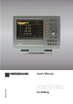
User's Manual
April 1996
POSITIP 855
for Lathes
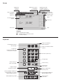
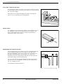
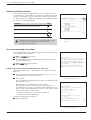
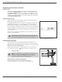
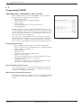
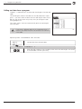
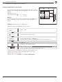
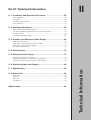
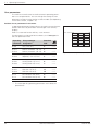
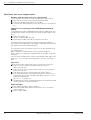
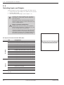
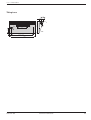
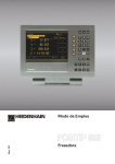
Screen
Operating
mode or
function
Reference marks
have been
crossed over
Operating mode
symbols (current
mode is highlighted)
Symbol for
soft-key row
Soft-key row
(with 5 soft
keys)
Plain language
dialog line
Input line
Distance-to-go
display
Soft keys
Feed rate
Tool
Symbols
Behind the position display:
: Scaling factor or oversize active
∅: Diameter display
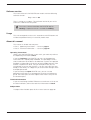
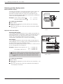
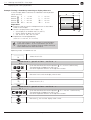
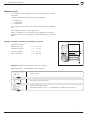
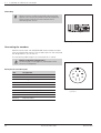
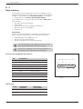
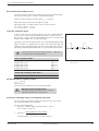
Keyboard
Change parameters
and settings
5 soft keys
(current functions are
indicated on screen)
Select or deselect
INFO functions
MOD
INFO
HELP
Select or deselect HELP
screens
7
8
9
4
5
6
1
2
3
Change sign
0
Clear entries or
error messages
Confirm entry
CE
ENT
Incremental
dimensions
Page through
individual screens
Access program blocks to
make changes, or switch
operating parameters
Select operating mode
Numeric input keys
Return to previous
soft-key level
GOTO
Go to program block or
operating parameter
Select tool or
input field
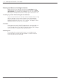
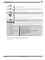
Software version
This User's Manual is for POSITIP 855 models with the following
software version:
Progr. 246 xxx 03.
The x's can be any numbers. The software version of your unit is
shown on a label on the rear panel.
This User 's Manual describes the POSITIP 855 for
turning. A separate manual is available for milling.
Usage
This unit corresponds to class A in accordance with EN 55022 and
will be used predominantly in industrially zoned areas
About this manual
This manual is divided into two parts:
• Part I: Operating Instructions .... starts on page 5
• Part II: Technical Information ..... starts on page 57
Operating Instructions
When using the POSITIP 855 in your work, you need only refer to
the Operating Instructions (Part I).
If you're a beginner with POSITIP, you can use the operating
instructions as a step-by-step workbook. This part begins with a
short introduction to the basics of coordinate systems and position
feedback, and provides an overview of the available features. Each
feature is explained in detail, using an example which you can
immediately try out on the machine — so you won't get "lost" too
deeply in the theory. As a beginner you should work through all the
examples presented.
If you're already an expert POSITIP user, you can use the
operating instructions as a comprehensive review and reference
guide. The clear layout and the subject index make it easy to find
the desired topics.
Technical Information
If you are interfacing the POSITIP 855 to a machine or wish to use
the data interfaces, refer to the technical information in Part II.
Subject Index
A subject index for both parts of this manual starts on page 86.
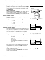
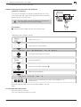
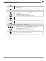
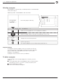
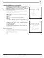
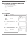
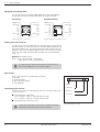
Dialog flowcharts
Dialog flowcharts are used for each example in this manual.
They are laid out as follows:
This area shows the
keys to press.
This area explains the key function or work step.
If necessary, supplementary information will also be included.
Prompt
This area shows the
keys to press.
This area explains the key function or work step.
If necessary, supplementary information will also be included.
If there is an arrow at the end of the flowchart, this means that it continues on
the next page.
A prompt appears with some actions (not always) at the top of the
screen. In the flowcharts the prompts always have a gray
background.
If two flowcharts are divided by a broken line, this means that you
can follow the instructions either above or below the broken line.
Some flowcharts also show the screen that will appear after you
press the proper keys.
Abbreviated flowcharts
Abbreviated flowcharts supplement the examples and explanations. An arrow ( ⇒ ) indicates a new input or a work step.
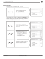
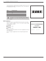
Special Notes in This Manual
Especially important information is shown as a separate note in a
gray box. Pay special attention to these notes. Ignoring them
would prevent effective use of the control, or even result in
damage to the tool or workpiece.
Symbols in the gray boxes
The symbols in the left of the gray boxes indicate the nature of the
provided information.
General information
for example on the machine tool.function
Information for the machine tool builder
for example that he must implement a certain function
Essential information
for example that a certain tool is needed for the
described function
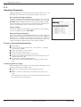
Part I: Operating Instructions
I
I - 1 Fundamentals of Positioning ..................................................... 7
I - 2 Working with POSITIP – First Steps ........................................ 13
Before you start ............................................................................................... 13
Switch-on ......................................................................................................... 13
Operating modes ............................................................................................. 14
The HELP, MOD and INFO functions .............................................................. 14
Selecting soft-key functions ............................................................................. 15
On-screen operating instructions ..................................................................... 15
Error messages ................................................................................................ 16
Selecting the unit of measurement .................................................................. 16
Selecting position display modes ..................................................................... 17
Entering tool data and setting the datum ......................................................... 18
Displaying and moving to positions .................................................................. 22
Turning with oversizes ..................................................................................... 22
Operating mode PROGRAMMING AND EDITING ........................................... 27
Selecting a program ......................................................................................... 28
Deleting programs ............................................................................................ 28
Editing programs .............................................................................................. 29
Entering program blocks .................................................................................. 30
Calling tool data from a program ...................................................................... 32
Transferring positions: Teach-in mode ............................................................. 33
Multipass cycle ................................................................................................ 36
Entering program interruptions ........................................................................ 38
Subprograms and program section repeats ..................................................... 39
Editing existing programs ................................................................................. 44
Deleting program blocks .................................................................................. 45
Transferring programs over the data interface ................................................. 46
I - 4 Executing Programs .................................................................. 49
I - 5 INFO: Pocket Calculator, Stopwatch, Taper Calculator ......... 51
To access the INFO functions .......................................................................... 51
Taper calculator ................................................................................................ 52
Stopwatch ........................................................................................................ 53
Pocket calculator .............................................................................................. 53
I - 6 User Parameters: The MOD Function ...................................... 55
Scaling factors .................................................................................................. 55
Entering user parameters ................................................................................. 56
Part II: Technical Information ............................................................ 57
Subject Index ...................................................................................... 86
Operating Instructions
I - 3 Programming POSITIP .............................................................. 27
I-1
Fundamentals of Positioning
I-1
Fundamentals of Positioning
You can skip this chapter if you are already familiar with the
concepts of coordinate systems, incremental and absolute
dimensions, nominal and actual positions, and distance-to-go.
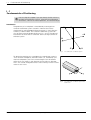
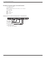
Introduction
The geometry of a workpiece is described by a rectangular or
Cartesian coordinate system (named in honor of the French
mathematician and philosopher René Descartes, in Latin Renatus
Cartesius, 1596 to 1650). The Cartesian coordinate system consists of three mutually perpendicular axes X, Y and Z. The point of
intersection of these axes is called the datum (or origin) of the coordinate system.
+Y
+Z
+X
–X
–Z
Fig. 1:
–Y
The Cartesian coordinate system
To determine positions on a workpiece, the coordinate system is
“laid” onto the workpiece. With lathe work (i.e., rotationally symmetrical workpieces), the Z axis move along the axis of rotation
while the X axis moves in the direction of the radius or diameter.
The Y axis can be disregarded since it would always have the same
values as the X axis.
X
Fig. 2:
POSITIP 855
Operating Instructions
Z
The Cartesian coordinate system with
lathe work
7
I-1
Fundamentals of Positioning
Cross slide, saddle and top slide
On conventional lathes, the tool is mounted on a slide that moves
in the direction of the X axis (the cross slide) and in the direction of
the Z axis (the saddle).
Most lathes have a top slide above the saddle. The top slide
moves in Z axis direction and is designated ZO.
+ZO
+Z
ZO
X
+X
Z
Fig. 3:
Axes of movement on a lathe
Datum setting
The workpiece drawing normally specifies the workpiece face as
the “absolute” datum, and indicates the axis of rotation. The
datum setting procedure assigns the origin of the absolute
coordinate system to this datum.
X
Fig. 4:
Z
The origin of the Cartesian coordinate
system is the workpiece datum
Determining and entering tool data
Your POSITIP display unit should show you the absolute position
of the workpiece regardless of the length and shape of the
particular tool being used. For this reason you must determine
the tool data (tool preset) and enter them. First touch the
workpiece with the cutting edge of the tool and then enter the
associated display value for that position.
You can enter tool data for up to 99 tools. When you have set
the datum for a new workpiece, all tool data are referenced to
the new workpiece datum.
See examples starting on page 19.
T1
Fig. 5:
8
Operating Instructions
T2
T3
These tools have different tool data
POSITIP 855
I-1
Fundamentals of Positioning
Nominal position, actual position and distance-to-go
The positions to which the tool is to move are called the nominal
positions, while the position at which the tool is actually located at
any given moment is called the actual position (see Figure 6). The
distance from the nominal position to the actual position is called
the distance-to-go.
Sign for distance-to-go
The distance-to-go carries a positive sign when the path from the
actual to the nominal position is in the negative axis direction.
The distance-to-go carries a negative sign when the path from the
actual to the nominal position is in the positive axis direction.
Z
R
S
I
X
Absolute workpiece positions
Each position on the workpiece is uniquely defined by its absolute
coordinates (see Figure 7).
Absolute coordinates of position 1 :
X = 5 mm
Z = –35 mm
:
0
2
Nominal position S , actual position I
and distance-to-go R
35
Absolute coordinates of position
X = 15 mm
Z = –65 mm
Fig. 6:
65
Example:
If you are working according to a workpiece drawing with absolute
dimensions, you are moving the tool to the coordinates.
Z
Incremental workpiece positions
5
A position can also be defined relative to the previous nominal position (see Figure 8). The datum for the dimension is then located
at the previous nominal position. Such coordinates are termed incremental coordinates (increment = increase) or chain dimensions (since the position is defined by a chain of dimensions).
Incremental coordinates are identified by a preceding I.
Example:
1
Fig. 7:
Incremental coordinates of position 3 referenced to
position 1 :
IX = 10 mm
IZ = 0 mm
Incremental coordinates of position 2 referenced to
position 3 :
IZ = –30 mm
Sign for incremental dimensioning
An incremental dimension has a positive sign when the axis is
moved in the positive direction.
An incremental dimension has a negative sign when the axis is
moved in the negative direction.
POSITIP 855
Operating Instructions
X
Positions 1 and 2 are absolute
workpiece positions
30
Incremental coordinates of position 2 referenced to
position 1 :
IX = 10 mm
IZ = –30 mm
If you are working according to a workpiece drawing with incremental dimensions, you are moving the tool by the dimension.
15
2
35
5
Z
10
1
2
3
X
Fig. 8:
Positions 1 and 3 are ncremental
workpiece positions
9
Fundamentals of Positioning
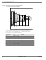
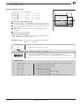
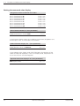
Workpiece drawing with absolute dimensions
(in accordance with ISO 129 standard)
P6
P5
P4
P1
P2
80
60
100
120
180
P3
P0
40
P7
80
Example:
60
I-1
Z
0
40
80
120
150
180
220
X
A list of coordinates corresponding to this example is advantageous when
you are working in the PROGRAMMING AND EDITING operating mode.
The X-coordinate values are given as diameters.
Coordinates
for
10
X∅
[mm]
Z
[mm]
Remarks
P0
40
0
Face
P1
80
– 40
P2
60
– 80
Recess
P3
60
– 120
Recess
P4
100
– 120
P5
120
– 150
P6
180
– 180
P7
180
– 220
Operating Instructions
POSITIP 855
I-1
Fundamentals of Positioning
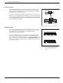
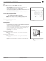
Position encoders
The position encoders convert the movements of the machine
axes into electrical signals. POSITIP then evaluates these signals,
determines the actual position of the machine axes, and displays
the position as a numerical value.
Z
If power is interrupted, the relationship between the machine axis
positions and the calculated actual positions is lost. The reference
marks on the position encoders and the reference mark evaluation
feature (REF) enable POSITIP to re-establish this relationship again
when the power is restored.
Fig. 9:
Linear encoder, here for the Z axis
Reference marks
The scales of the position encoders contain one or several reference marks. When a reference mark is crossed over, a signal is
generated identifying that position as a reference point
(scale datum = machine datum).
When this reference mark is crossed over, the POSITIP's reference mark evaluation feature restores the relationship between
axis slide positions and display values as you last defined it by setting the datum. If the linear encoders have distance-coded reference marks, you only need to move the machine axes a maximum
of 20 mm to do this.
Fig. 10: Linear scales: with distance-coded
reference marks (upper illustration)
and one reference mark (lower
llustration)
POSITIP 855
Operating Instructions
11
I-1
Fundamentals of Positioning
NOTES
12
Operating Instructions
POSITIP 855
I-2
Working with POSITIP – First Steps
I-2
Working with POSITIP – First Steps
Before you start
You can cross over the reference marks after every switch-on.
REF appears in the input line on the screen when all the reference
marks have been crossed over. If you set a new datum, POSITIP
automatically stores the new relationship between axis slide positions and display values.
Working without reference mark evaluation
You can also use POSITIP without crossing over the reference
marks — simply press the soft key No REF.
Note that if you do not cross over the reference marks,
a new datum point you set will not be stored. This
means that after a power interruption the relationship
between axis slide positions and display values cannot
be restored.
Fig. 11: REF display on screen
Switch-on
0➤1
Turn on the power
and
press any key.
Cross over the reference marks in all axes
(in any sequence).
Do not cross over the reference marks.
Note: In this case the relationship between axis slide positions and
display values will be lost if the power is interrupted.
Your POSITIP is now ready for operation and is in the operating
mode ACTUAL VALUE.
POSITIP 855
Operating Instructions
13
I-2
Working with POSITIP – First Steps
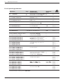
Operating Modes
The operating mode determines which functions are available to
you.
Available functions
Mode
Position display for basic
machining tasks;
Tool presetting;
Datum setting
ACTUAL
VALUE
Distance-to-go display;
Turning with oversize
DISTANCETO-GO
Storage of work steps for
small-lot production
PROGRAMMING
AND EDITING
Run programs previously
created in the PROGRAMMING
AND EDITING mode
EXECUTE
PROGRAM
Key
You can switch to another operating mode at any time by pressing
the key for the desired mode.
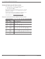
The HELP, MOD and INFO functions
You can call the HELP, MOD and INFO functions at any time.
To call a function:
➤ Press the key for the desired function.
To leave a function:
➤ Press the same key again.
Available functions
14
Function name Key
On-screen operating instructions: graphics and text
keyed to the current screen
contents
HELP
User parameters:
To redefine POSITIP's basic
operating characteristics
MOD
Taper calculator, stopwatch,
pocket calculator
INFO
HELP
MOD
INFO
Operating Instructions
POSITIP 855
I-2
Working with POSITIP – First Steps
Selecting soft-key functions
The soft-key functions are grouped into one or more rows. The
number of rows is indicated by a symbol at the upper right of the
screen. If no symbol is shown, that means there is only one row
for the function. The highlighted rectangle in the symbol indicates
the current row being displayed.
Function
Key
Page forward through the soft-key rows
Page backward through the soft-key rows
Go back one level
Whenever you press the key for an operating mode,
POSITIP displays the soft keys with the main
functions for that mode.
Fig. 12: The symbol for soft-key rows.
Here, the first row is being displayed
On-screen operating instructions
The integrated operating instructions provide you with information
and assistance in any situation.
To call the operating instructions:
➤ Press the HELP key.
➤ Use the paging keys if the explanation is spread over more
than one screen page.
To leave the operating instructions:
➤ Press HELP again.
Example: On-screen operating instructions for NOTE/SET
The function NOTE/SET is described in this manual starting on
page 21.
➤ Select NOTE/SET by pressing the soft key Note/Set in
the operating mode ACTUAL VALUE.
➤ Press HELP.
The first page of the operating instructions for NOTE/SET appears on the screen.
Fig. 13: On-screen operating instructions for
NOTE/SET (page 1 of 2)
Page reference at the lower right of the screen:
The number in front of the slash is the current page; the
number behind the slash is the total number of pages for this
topic. The on-screen operating instructions now contain the following information on NOTE/SET:
• General information on the function (page 1/2)
• Sequence of entries (page 2/2)
To leave the operating instructions:
➤ Press HELP again.
Fig. 14: On-screen operating instructions for
NOTE/SET (page 2 of 2)
POSITIP 855
Operating Instructions
15
I-2
Working with POSITIP – First Steps
Error messages
If an error occurs while you are working with POSITIP, a message
will come up on the screen in plain English.
To call an explanation of the error:
➤ Press the HELP key.
To clear the error message:
➤ Press the CE key.
Blinking error messages
WARNING
Blinking error messages mean that the operational
reliability of the POSITIP has been impaired.
If a blinking error message occurs:
➤ Note down the error message displayed on the screen.
➤ Switch off the power to the POSITIP.
➤ Attempt to correct the problem with the power off.
➤ If the blinking error message recurs, notify your customer
service agency.
Selecting the unit of measurement
Positions can be displayed in millimeters or inches. If you choose
inches, inch will be displayed at the top of the screen next to
REF.
To change the unit of measurement:
➤ Press MOD.
➤ Page to the soft key row containing the user parameter
mm or inch.
➤ Choose the soft key mm or inch to change to the other unit.
➤ Press MOD again.
For more information on user parameters, see Chapter I - 6.
Fig. 15: The inch indicator
16
Operating Instructions
POSITIP 855
I-2
Working with POSITIP – First Steps
Selecting position display modes
Radius/diameter display
Example: Radius display, position 1
Diameter display, position 1
Z
40
Drawings for lathe parts usually give diameter values. When you
turn the part, however, you infeed the tool in radius values.
POSITIP can display either the radius or the diameter for you.
When the diameter is being displayed, the diameter symbol (∅) is
shown next to the position value.
X = 20 mm
X = 40∅ mm
1
20
X
To switch over the display
➤ Press MOD.
➤ Page with the paging keys to the soft key row containing
Radius or Dia.
➤ Press this soft key to switch from radius to diameter display
or vice-versa.
Fig. 16: Workpiece for radius/diameter display
example
Separate value/sum display
Separate value display
In this display mode the positions of the saddle and top slide are
displayed separately. The position displays are referenced to the
datum points which you set for the axes. When an axis slide
moves, only the position display for that axis changes.
The top slide is identified with a small O, for example ZO.
Sum display
In this mode the position values of the saddle and top slide are
added together. The sum display shows the absolute position of
the tool, referenced to the workpiece datum.
When the sum display mode is active, a small S is shown next to
the axis designation, for example ZS.
40
Z
0 +10
+25
Z
Z0
Z
Example: Separate value (see Fig. 17): Z = +25.000 mm
ZO = +15.000 mm
Sum display (see Fig. 17):
ZS = +40.000 mm
Z0
-10 0
The sum display will show correct values only if the actual
position values of both axis slides were correctly added
and entered (with sign) when setting the datum for the
“sum.”
+15
Fig. 17: Workpiece for separate value/sum
display example
To switch over the display
➤ Press MOD.
➤ Page with the paging keys to the soft key row containing Sum
or Seprt.
➤ Press this soft key to switch from separate value display to
sum display or vice-versa.
POSITIP 855
Operating Instructions
17
I-2
Working with POSITIP – First Steps
Entering tool data and setting the datum
Before you can use a tool you must enter its tool data (cutting
edge position). You can enter the data for up to 99 tools. A workpiece datum must also be entered before you can start machining.
Normally the workpiece face (flat surface) is given the value Z = 0.
“ Freezing” a position when turning the first diameter
If you want to measure the diameter of the workpiece after turning
the first diameter, you can store (“freeze”) the actual position
before retracting the tool. This is done in the ACTUAL VALUE
operating mode with the Note/Set function. See page 21 for an
explanation of this function and an example.
Tool table
When you preset tools, POSITIP automatically stores the tool data
in a table. You can access the tool table with a user parameter.
If you change values in the table, the position display will no longer
show the values it displayed after tool presetting.
Selecting tools
The number of the current tool is shown in a small box at the
lower right of the screen (next to the letter T). Use the vertical
arrow keys to select another tool.
18
Operating Instructions
POSITIP 855
I-2
Working with POSITIP – First Steps
Entering tool data and setting the datum
Example: Setting the workpiece datum (zero point)
The datum is set to zero for the sum display of the Z axis. All tool
data entered are automatically referenced to this datum.
Preparation:
➤ Select the tool number (tool data) with the vertical arrow keys.
Z=0
Z
Operating mode: ACTUAL VALUE
Machine the workpiece face.
Leave the cutting edge of the tool at the face.
/
Page to the function Datum.
Select Datum.
Select the axis (ZS).
Datum
ZS = +0
Set the datum (workpiece face) to the indicated value.
ENT
1
POSITIP 855
0
Setting
ENT
Enter a value, for example 10. Confirm entry.
Operating Instructions
19
I-2
Working with POSITIP – First Steps
Entering tool data and setting the datum
Example: Entering tool data when the workpiece
diameter is known
Preparation:
➤ Select the tool number with the vertical
arrow keys.
Z
2
10
1
20
X
Operating mode: ACTUAL VALUE
Turn the first diameter 1 in the X axis.
Select the axis (X).
Tool Setting
X = ...
1
0
ENT
Enter the position of the tool tip, for example X = 10 mm.
Confirm entry.
Touch the workpiece face 2 with the tool.
Select the axis (ZS).
Tool Setting
ZS = ...
0
ENT
Set the position display for the tool tip to zero, ZS = 0.
Confirm entry.
POSITIP stores the tool data under the tool number in the tool
table.
Set the tool data for all other tools as described here.
20
Operating Instructions
POSITIP 855
I-2
Working with POSITIP – First Steps
Entering tool data and setting the datum
Example: Entering tool data when the workpiece
diameter is unknown
Turn the first diameter and freeze the tool position with Note.
Then retract the tool, measure the diameter and set the frozen
position to the measured value.
?
Z
?
1
The value to be entered will depend on whether you
have selected radius or diameter display.
X
2
Preparation:
➤ Select the tool number with the vertical arrow keys.
Operating mode: ACTUAL VALUE
Select Note/Set.
Select the axis, for example X.
Turn
1st
diameter
in
X
axis
Turn the first diameter in the X axis.
Freeze the position.
Retract, for example to position 2 .
Measure the workpiece.
Enter
+ 0
1
5
ENT
value
for
X
Enter the measured diameter or radius, for example 15 mm.
Confirm entry.
POSITIP stores the tool data under the tool number in the tool
table.
To cancel the Note/Set function
Press the soft key Escape.
You can cancel the function at any time.
POSITIP 855
Operating Instructions
21
I-2
Working with POSITIP – First Steps
Displaying and moving to positions
Distance-to-go
Although it is often sufficient to have POSITIP display the coordinates of the actual position of the tool, it is usually better to use
the distance-to-go feature — this enables you to approach nominal positions simply by traversing to display value zero. Even when
working with distance-to-go you can enter coordinates in absolute
or incremental dimensions.
Graphic positioning aid
When you are traversing to display value zero, POSITIP displays a
graphic positioning aid (see Figure 18).
The graphic positioning aid is located in a rectangle just below the
display for the active axis. Two triangular marks in the center of
the rectangle symbolize the nominal position you want to reach.
The small square symbolizes the axis slide. An arrow indicating the
direction appears in the square while the axis is moving, so you
can easily tell whether you are moving towards or away from the
nominal position.
Note that the square does not begin to move until the axis slide is
near the nominal position.
POSITIP can show the absolute position instead of the
graphic positioning aid. You can switch between the two
modes with operating parameter P 91 (see Chapter II - 2).
Fig. 18: The graphic positioning aid
Turning with oversizes
You enter oversizes in the user parameters (see Chapter I - 6).
Oversizes are automatically taken into account in the distance-togo mode. When the displayed distance-to-go is 0, only the finishing
allowance remains to be machined.
When you have set the user parameter Oversize On/Off to
On, a symbol for oversize ( ) appears behind the display value.
CAUTION
will also appear if you've activated a scaling factor for
the axis. If the symbol appears but you're not sure
whether it indicates a scaling factor or an oversize,
check the settings of the user parameters.
Z
X
Entry values for oversize or undersize
Oversize: Positive entry value (up to 999.999 mm).
Undersize: Negative entry value (down to –999.999 mm).
Fig. 29: Oversizes for X and Z
22
Operating Instructions
POSITIP 855
I-2
Working with POSITIP – First Steps
MOD
Displaying and moving to positions
Entering oversizes
➤
➤
➤
➤
➤
Press MOD.
Scroll to the user parameter Oversize.
Press the soft key Oversize X (for example).
Enter the desired oversize for the axis (including the sign).
Press ENT.
This returns you to the main menu for the user parameters.
➤ If desired, enter an oversize for the second axis.
➤ Switch the soft key Ovrsize ON / OFF to ON.
This activates the oversizes you entered.
➤ Leave the user parameters:
Press MOD.
The entered oversizes will now be taken into account when you
traverse to display value zero with the distance-to-go display.
To deactivate oversizes
Fig. 20: Entering an oversize
When you want to work without oversizes again:
➤ Switch the soft key Ovrsize ON / OFF to
OFF, or enter 0 for the oversize.
1
= +50.000 mm
= +52.000 mm
= +48.000 mm
CAUTION
When the soft key Ovrsize ON / OFF is set to ON
oversizes will be effective on every position which you
move to with DISTANCE-TO-GO.
POSITIP 855
Z
40
2. Radius display for X, position 2
Position of the tool cutting edge:
without oversize:
X
with oversize (+2.000 mm):
X
with undersize (–2.000 mm): X
100
Example: Effect of an oversize in the X axis
1. Diameter display for X, position 1
Position of the tool cutting edge:
without oversize:
X∅ = +40.000 mm
with oversize (+2.000 mm):
X∅ = +44.000 mm
with undersize (–2.000 mm): X∅ = +36.000 mm
Operating Instructions
2
X
Fig. 21: Workpiece drawing for the example on
Oversizes. Tool positions without oversize or undersize
23
I-2
Working with POSITIP – First Steps
Position
Position
Position
Position
Z
Z
Z
=
0 mm
= –20 mm
= –20 mm
IZ = –45 mm
1
2
3
4
45
0
Example: Turning a shoulder by traversing to display value zero
In this example, both incremental and absolute nominal position
values are used.
20
Displaying and moving to positions
X
X
= 15 mm
= 15 mm
IX = +5 mm
IX = 0 mm
Z
Preparation:
➤ Preset the tool and set the workpiece datum as described
earlier in this chapter.
➤ Set the user parameters (see Chapter I - 6):
• Sum display ZS or for both axes (XS and ZS)
• Radius display for both axes X and Z
• Set Ovrsize ON / OFF to OFF
➤ Preposition the tool appropriately
(such as X = +20 mm, Z = +10 mm).
1
15
5
2
4
3
X
If you want to turn a larger shoulder, use the Multipass
cycle (see Chapter I - 3). This cycle allows you to turn
the shoulder in any number of infeeds without having to
enter coordinates for each feed move.
Operating mode: DISTANCE-TO-GO
Select the axis (X).
Nominal
X + ....
1
5
position
value
?
Enter the coordinate for nominal position 1 : X = 15 mm. Confirm entry.
The positioning aid appears for the X axis;
the nominal position remains at the top of the screen.
ENT
Move the X axis until the display value is zero.
Select the axis ( ZS ).
Nominal
ZS + ....
2
0
ENT
position
value
?
Enter the coordinate for nominal position 2 : ZS = –20 mm. Confirm entry.
The positioning aid appears for the ZS axis;
the nominal position remains at the top of the screen.
Move the ZS axis until the display value is zero.
24
Operating Instructions
POSITIP 855
I-2
Working with POSITIP – First Steps
Displaying and moving to positions
Select the axis (X).
Nominal
X + ....
position
value
?
Enter the coordinate for nominal position 3 : 5 mm and
mark the entry as an incremental dimension: IX = 5 mm.
Confirm entry.
The positioning aid appears for the X axis;
the nominal position remains at the top of the screen.
5
ENT
Move the X axis until the display value is zero.
Select the axis (ZS).
Nominal
ZS + ....
4
5
ENT
position
value
?
Enter the coordinate for nominal position 4 : ZS = –45 mm and
mark the entry as an incremental dimension: IZS = –45 mm.
Confirm entry.
The positioning aid appears for the ZS axis;
the nominal position remains at the top of the screen.
Move the ZS axis until the display value is zero.
POSITIP 855
Operating Instructions
25
I-2
Working with POSITIP – First Steps
NOTES
26
Operating Instructions
POSITIP 855
I-3
Programming POSITIP
I-3
Programming POSITIP
Operating mode PROGRAMMING AND EDITING
The available functions in the PROGRAMMING AND EDITING
operating mode are divided into four groups:
• Programming mode
for entering, running and editing programs
• Teach-in mode
• External mode
for transferring programs to an external device
• Deleting programs
Programs contain the work steps for workpiece machining. You
can edit programs, add work steps to them and run them as often
as you wish. POSITIP can store a maximum of 20 programs with a
total of 2000 nominal positions. A single program can contain a
maximum of 1000 nominal positions.
The External mode enables you to store programs with the
HEIDENHAIN FE 401 floppy disk unit and load them into POSITIP
again on demand — you don't need to re-enter them manually.
You can also transfer programs to a personal computer or printer.
Fig. 22: The main menu in the operating mode
PROGRAMMING AND EDITING
Programmable functions
•
•
•
•
•
Nominal position values (axes with saddle and top slides:
nominal value of the summed position, see “Selecting position
display modes” in Chapter I - 2)
Interrupt program
Multipass cycle:
Turning with any number of feed moves.
Program section repeats:
A section of a program only has to be entered once and can
then be run up to 999 times in succession.
Subprogramming:
A section of a program only has to be entered once and can
then be run at various places in the program.
Transfer position: Teach-in mode
This mode allows you to transfer the actual positions of the tool
directly into a program. In many cases the Teach-in function will
save you considerable keying effort.
What happens with finished programs?
For workpiece machining, programs are run in the operating mode
EXECUTE PROGRAM. See Chapter I - 4 for an explanation of this
mode.
POSITIP 855
Operating Instructions
27
I-3
Programming POSITIP
Selecting a program
Each program is identified by a number between 0 and 99 999 999
which you assign it.
Operating mode: PROGRAMMING AND EDITING
Go to the program directory.
Program
?
Select an existing program, such as program number 5.
5
1
number
9
Create a new program:
Give it a number which is not yet in the directory, such as 19.
Choose the unit of measurement.
ENT
Confirm your entry.
The selected program can now be entered, edited or run.
Program directory
The program directory appears when you choose the soft key
Program Number. The number in front of the slash is the program number, the number behind the slash is the number
of blocks in the program.
A program always contains at least two blocks.
To delete a program
If you no longer wish to keep a program in memory, you can
delete it:
➤ In the operating mode PROGRAMMING AND EDITING, press
the soft key Delete Program in the first soft key row.
➤ Enter the program number.
➤ Press ENT to delete the program.
28
Operating Instructions
POSITIP 855
I-3
Programming POSITIP
Editing programs
Operating mode: PROGRAMMING AND EDITING
Edit the last program selected
with Program Number,
such as program number 10.
Use the paging keys to display the programmable functions in the
different soft key rows. The screens shown at the right already
contain some program blocks. Turn to the next page of this manual
to learn how program blocks are entered.
The first soft key row provides
functions for entering and changing
coordinates.
/
/
/
POSITIP 855
The second soft key row provides
the following functions:
• Enter labels for subprograms
and program section repeats
• Interrupt program
• Call tool data
• Delete program blocks
The third soft key row contains the
Multipass cycle for turning with
any number of feed moves.
Operating Instructions
29
I-3
Programming POSITIP
Entering program blocks
Current block
The current block is shown between the two dashed lines. New
blocks are inserted behind the current block. When the END PGM
block is between the dashed lines, no new blocks can be inserted.
Function
Soft key/Key
Go up one block
Go down one block
Cancel numerical entry
CE
Delete current block
Going directly to a program block
Scrolling to the desired block with the arrow keys can be timeconsuming with long programs. A quicker way is to use the GOTO
function. This enables you to move directly to the block you wish
to change or add new blocks behind.
Operating mode: PROGRAMMING AND EDITING
Select Edit.
Press the GOTO key.
GOTO
Block
5
8
ENT
30
number
?
Enter a block number, such as 58.
Confirm your entry.
Block number 58 is now the current block.
Operating Instructions
POSITIP 855
I-3
Programming POSITIP
Entering program blocks
Position
Position
Position
Position
1
2
3
4
Z
Z
Z
Z
=
0 mm
= –20 mm
= –20 mm
= –65 mm
X
X
65
The datum is the workpiece zero.
=
=
IX =
X =
15
15
+5
20
0
Example: Milling a shoulder
20
mm
mm
mm
mm
Z
Summary of programming steps
➤ In the main menu PROGRAMMING AND EDITING use the
Program Number soft key to access the program directory.
➤ Key in the number of the program you want to work on, and
press ENT.
➤ Select Edit in the main menu PROGRAMMING AND
EDITING.
➤ Enter the nominal positions.
1
15
5
2
4
3
X
Running a finished program
When a program is finished it can be run in the EXECUTE PROGRAM operating mode (see Chapter I - 4).
Example of entry: Entering a nominal position into a program
(block 3 in the example)
Select the coordinate axis (X axis).
Nominal
1
5
ENT
position
value
?
Enter the nominal position value (X = 15 mm). Confirm entry.
The nominal position is now the current block (between the dashed lines).
Program blocks
0
1
2
3
4
5
6
7
POSITIP 855
BEGIN PGM 10
X+50.000
Z+20.000
X+15.000
Z–20.000
IX+5.000
Z–65.000
END PGM 10
MM
MM
Start of program, program number and unit of measurement
Pre-position the tool in the X axis
Pre-position the tool in the Z axis
X coordinate, position 1
Z coordinate, position 2
Incremental X coordinate, position 3
Z coordinate, position 4
End of program, program number and unit of measurement
Operating Instructions
31
I-3
Programming POSITIP
Calling tool data from a program
Chapter I - 2 explained how to enter tool data (lengths) into the tool
table.
The tool lengths stored in the table can also be called from a program — you don't need to select the new tool lengths from the table with the vertical arrow keys every time you change the tool
during program run.
The TOOL CALL command automatically pulls the tool lengths
from the table.
If you enter a different tool axis in the program than is
stored in the table, POSITIP will store the new tool axis
in the table.
Fig. 23: The tool table on the screen
Operating mode: PROGRAMMING AND EDITING
Call tool data from the tool table.
Tool
4
32
ENT
number
?
Enter the tool number (4, for example) under which the tool lengths are stored
in the tool table. Confirm your entry.
Operating Instructions
POSITIP 855
I-3
Programming POSITIP
Transferring positions: Teach-in mode
Teach-in programming offers the following two options:
• Enter nominal position, transfer nominal position into program,
move to positions by traversing to display value zero:
TEACH-IN / DISTANCE TO GO
• Move to a position and transfer the actual value into a program:
TEACH-IN / ACTUAL POSITION
You can change transferred position values with TEACH-IN /
PROGRAM.
65
Programming example for TEACH-IN / DISTANCE TO GO
Generating a program while turning a shoulder
0
Preparation
➤ With Program number select the program you want to
transfer positions into.
➤ Select the tool number (tool data) with the vertical arrow keys.
20
With Teach-in you machine a workpiece according to the workpiece drawing. POSITIP transfers the nominal position coordinates
directly into the program while you machine. Pre-positioning and
retraction moves can be selected as desired and entered like drawing dimensions.
Z
Z
Z
Z
=
0 mm
= –20 mm
= –20 mm
= –65 mm
X = 15 mm
X = 15 mm
IX= +5 mm
X = 20 mm
1
2
15
5
Position 1
Position 2
Position 3
Position 4
Z
4
3
X
Operating mode: PROGRAMMING AND EDITING
Select Teach-In.
The functions for TEACH-IN / DISTANCE TO GO
are available immediately in the first soft key row.
Example: Transfer the X coordinate of corner point 1 into a
program.
Select the coordinate axis (X).
Nominal
1
5
ENT
position
value
?
Enter the nominal position value (X = 15 mm). Confirm entry.
POSITIP displays the positioning aid for traversing to zero. The entered
nominal position value appears in the input line at the top of the screen.
Move the entered axis until the display value is zero.
Then enter and transfer further coordinates.
POSITIP 855
Operating Instructions
33
I-3
Programming POSITIP
Transferring positions: Teach-in mode
Programming example for TEACH-IN / ACTUAL POSITION
Transfer position and depth of grooves into a program
With TEACH-IN / ACTUAL POSITION you can generate a program that contains the actual positions of the tool.
Z
X
Operating mode: PROGRAMMING AND EDITING
Select Teach-In.
/
Go to TEACH-IN / ACTUAL POSITION.
Example:: Transfer the depth of a groove
Machine the groove on the workpiece.
Select the coordinate axis (X).
Transfer
ENT
34
actual
value
X
?
Transfer the actual value for the X axis into the program. The transferred
program block appears in the input line at the top of the screen.
Operating Instructions
POSITIP 855
I-3
Programming POSITIP
Transferring positions: Teach-in mode
Changing nominal positions after they have been transferred
Positions which you have transferred into a program with Teach-in
can be changed. It is not necessary to leave the Teach-in mode to
do so. Enter the new value in the input line.
Example: Changing a block transferred with Teach-in
Operating mode: PROGRAMMING AND EDITING, Teach-In
/
Go to TEACH-IN / PROGRAM.
The current program appears on the screen.
/
With the arrow keys (or GOTO), move to the block you wish to change.
Select the block.
Nominal
position
value
?
0
Enter a new nominal position value (such as 0).
ENT
Confirm your changes.
Functions for changing a Teach-in program
Function
Soft key
Abort and return to main menu
PROGRAMMING AND EDITING
Delete current block
POSITIP 855
Operating Instructions
35
I-3
Programming POSITIP
Multipass cycle
The multipass cycle enables you to turn a shoulder in any number
of infeeds.
You only need to enter three blocks into a program:
•
•
•
CYCL block
X coordinate
Z coordinate
The multipass cycle contains all information required for the operation.
Do not delete any blocks from the cycle.
When the program is run, POSITIP always displays the distanceto-go to the two nominal positions immediately following the CYCL
block.
50 mm
Shoulder diameter:
X =
10 mm
Start of shoulder:
Z =
0 mm
End of shoulder:
Z = –30 mm
0
Z
10
X =
50
Workpiece diameter
before machining:
30
Example: Turning a shoulder in any number of infeeds
X
Example: Entering the Multipass cycle into a program
Operating mode: PROGRAMMING AND EDITING
Select Edit.
/
Go to the third soft key row.
Select the Multipass cycle.
The program block CYCL 3.0 MULTIPASS appears on the screen.
36
Operating Instructions
POSITIP 855
I-3
Programming POSITIP
Multipass cycle
/
Go to the first soft key row.
Select the coordinate axis (X axis).
Nominal
5
position
value
?
Enter the nominal position value (X = 5 mm). Confirm entry.
ENT
Select the coordinate axis (ZS axis).
Nominal
3
0
ENT
position
value
?
Enter the nominal position value (ZS = –30 mm). Confirm entry.
Program blocks
0
1
2
3
4
5
6
7
8
9
10
BEGIN PGM 20 MM
X+80.000
Z+20.000
X+50.000
Z+0.000
CYCL 3.0 MULTIPASS
X+10.000
Z–30.000
X+80.000
Z+20.000
END PGM 20
MM
Start of program, program number and unit of measurement
Pre-position tool in the X axis
Pre-position tool in the Z axis
Approach the workpiece (X axis)
Approach the workpiece (Z axis)
Coordinates for a Multipass cycle follow this block
X coordinate of the shoulder
Z coordinate of the shoulder
Retract (X axis)
Retract (Z axis)
End of program, program number and unit of measurement
The cycle is performed in the operating mode EXECUTE PROGRAM
(see Chapter I - 4) by traversing to display value zero with any
number of infeeds.
POSITIP 855
Operating Instructions
37
I-3
Programming POSITIP
Entering program interruptions
You can divide a program into sections with stop marks. POSITIP
then executes the next block only after you press the soft key
Next Block.
Operating mode: PROGRAMMING AND EDITING
Select Edit.
/
Go to the second soft key row.
Press STOP to insert a program interruption.
38
Operating Instructions
POSITIP 855
I-3
Programming POSITIP
Subprograms and program section repeats
Subprograms and program section repeats only need to be entered
once in the program. You can then run them up to 999 times.
Subprograms can be run at any point in the program; program section repeats are run several times in direct succession.
Inserting program marks (labels)
You mark subprograms and program section repeats with labels
(abbreviated in the program with LBL).
Labels 1 to 99
Labels 1 to 99 mark the beginning of a subprogram or program
section repeat.
Label 0
Label 0 is used only to identify the end of a subprogram.
Label call
In the program, subprograms and program section repeats are
called with the command CALL LBL.
The command CALL LBL 0 is not allowed.
Subprogram:
A subprogram called with CALL LBL is executed immediately after the CALL LBL block.
Fig. 24: On-screen operating instructions for
subprograms (page 5 of 5)
Program section repeat:
The program section located before the CALL LBL block is executed. You enter the number of desired repeats with the CALL
LBL command.
Nesting program sections
Subprograms and program section repeats can also be “nested.”
For example, a subprogram can in turn call another subprogram or
repeat a program section repeat.
Maximum nesting depth: 8 levels.
POSITIP 855
Fig. 25: On-screen operating instructions for
program section repeats (page 3 of 5)
Operating Instructions
39
I-3
Programming POSITIP
Subprograms and program section repeats
0
5
20
50
70
Example: Subprogram for tool change
:
X = +30 mm
Z = +5 mm
Z
20
W
30
Coordinates of the
tool change position
40
The coordinates of the tool change position are written in a subprogram. To activate the tool change process you just call the subprogram.
Remark
A recessing tool (width 4 mm) is inserted to turn the groove. The
tool is moved back to the change position after the groove is
turned.
30
W
X
Example: Setting a label for a subprogram
Operating mode: PROGRAMMING AND EDITING
Select Edit.
/
Go to the second soft-key row.
Insert a label (LBL) for a subprogram.
POSITIP offers the lowest available label number as a default entry.
Label
?
Accept the default label number.
ENT
9
number
ENT
Enter a label number (such as 9). Confirm entry.
The current block now contains the set label LBL 9.
The beginning of a subprogram or program section repeat is now
marked with the label. Enter the program blocks for the subprogram after the LBL block.
Label 0 (LBL 0) is used only for the end of a subprogram.
40
Operating Instructions
POSITIP 855
I-3
Programming POSITIP
Subprograms and program section repeats
Example: Entering a subprogram call – CALL LBL
/
Go to the second soft-key row.
Call the label.
POSITIP offers the label number which was last set.
Label
number
ENT
9
ENT
?
Accept the default label number.
Enter the label number (9). Confirm entry.
The current block now contains the called label LBL 9.
For subprograms you can ignore the question “Repeat REP ?”.
Press the soft key to confirm that a subprogram is being called.
After the CALL LBL block in the operating mode
EXECUTE PROGRAM, POSITIP executes the blocks in the subprogram that are located between the LBL block with
the called number and the next block containing LBL 0.
Note that the subprogram will be executed at least once even
without a CALL LBL block.
Program blocks
0
BEGIN PGM 30 MM
Start of program, program number and unit of measurement
1
2
3
4
LBL 9
X+60.000
Z+5.000
LBL 0
Beginning of subprogram 9
X coordinate of the tool change position (diameter)
Z coordinate of the tool change position
End of subprogram 9
5
6
Z+2.000
X+64.000
Pre-position, Z coordinate
Pre-position, X coordinate
7
8
9
CYCL 3.0 MULTIPASS
X+20.000
Z–20.000
Coordinates for a multipass cycle follow
X coordinate of the first shoulder (for the diameter)
Z coordinate of the first shoulder
10
11
X+40.000
Z–70.000
X coordinate of the second shoulder (diameter)
Z coordinate of the second shoulder
12
CALL LBL 9
Call subprogram 9: go to tool-change position,
blocks 1 to 4 are executed
13
STOP
Program interruption for tool change
14
15
16
Z–52.000
X+30.000
IX+40.000
Pre-positioning for recess operation
Machine recess (diameter)
Retract
17
CALL LBL 9
Call subprogram 9: return to tool-change position,
blocks 1 to 4 are executed
18
END PGM 30 MM
End of program, program number and unit of measurement
POSITIP 855
Operating Instructions
41
I-3
Programming POSITIP
Subprograms and program section repeats
Entering and calling program section repeats
A program section repeat is entered like a subprogram. Since the
end of the program section is identified simply by the command to
repeat the section (CALL LBL), label 0 is not set.
Display of the CALL LBL block with a program section repeat
The screen displays (for example): CALL LBL 6
REP
10 / 10
The two numbers with the slash between them indicate that this is
a program section repeat.
The number in front of the slash is the number of repeats you entered.
The number behind the slash is the number of repeats remaining
to be performed.
Coordinates of
first groove
Number of grooves
20
Z = –25 mm
X = 25 mm
20
0
20 mm
20
Z
25
Spacing between grooves
25
Example: Program section repeat for several identical grooves
4
X
Example: Insert a label for a program section repeat
Operating mode: PROGRAMMING AND EDITING
Select Edit.
/
Go to the second soft-key row.
Set a program mark (LBL) for a program section repeat.
POSITIP offers the lowest available label number as a default entry.
Label
ENT
8
ENT
number
?
Accept the default label number.
Enter a label number (8). Confirm entry.
The current block now contains the set label: LBL 8.
Enter the blocks for the program section repeat after the LBL
block.
42
Operating Instructions
POSITIP 855
I-3
Programming POSITIP
Subprograms and program section repeats
Example: Entering a program section repeat – CALL LBL
/
Go to the second soft-key row.
Call label.
POSITIP offers the label number that was last set.
Label
number
Accept the default label number.
ENT
8
Enter label number (8). Confirm entry.
The called label is now in the current block: CALL LBL 8.
ENT
Repeat
3
?
REP
?
Enter the number of repeats (3). Confirm entry.
ENT
After a CALL LBL block in the operating mode PROGRAMMING
AND EDITING, POSITIP repeats the program blocks that are located behind the LBL block with the called number and before the
CALL LBL block.
Note that the program section will always be executed one more
time than the programmed number of repeats.
Program blocks
0
1
2
3
4
BEGIN PGM 40 MM
X+80.000
Z+20.000
X+40.000
Z–5.000
Start of program, program number and unit of measurement
Pre-position the tool (X axis)
Pre-position the tool (Z axis)
X coordinate for pre-positioning
Z coordinate for pre-positioning
5
6
7
8
9
LBL 8
IZ–20.000
X+25.000
X+40.000
CALL LBL 8
Beginning of program section 8
Move to groove position
Turn groove
Retract
Repeat program section 8 between blocks 5 and 9 three times
10
11
X+80.000
END PGM 40 MM
POSITIP 855
REP
3/3
Retract
End of program, program number and unit of measurement
Operating Instructions
43
I-3
Programming POSITIP
Editing existing programs
You can edit existing programs, for example to correct keying errors. POSITIP supports you with plain language dialogs — just as
when you are creating a new program.
Program numbers can be changed by selecting the BEGIN or END
block and entering a new program number.
Confirm your changes
You must confirm each change with the ENT key for it to become
effective.
Example: Editing a program block
Operating mode: PROGRAMMING AND EDITING
/
Move to the block you wish to edit.
Select the block.
0
2
ENT
Edit the block, for example enter a new nominal position value (20).
Confirm the change.
Function
Key
Select the next-lowest program block
Select the next-highest program block
Go directly to block number
GOTO
Select program block to edit
Confirm change
44
ENT
Operating Instructions
POSITIP 855
I-3
Programming POSITIP
Deleting program blocks
You can delete any blocks in existing programs except the BEGIN
and END blocks.
When a block is deleted, POSITIP automatically renumbers the remaining blocks. The block before the deleted block then becomes
the current block.
Example: Deleting a program block
Operating mode: PROGRAMMING AND EDITING
Select Edit.
/
Move to the block you wish to delete
(or use the GOTO key).
/
Go to the second soft-key row.
Press Delete Block.
It is also possible to delete an entire program section:
➤ Select the last block of the program section.
➤ Press the soft key Delete Block repeatedly until all blocks
in the section have been deleted.
POSITIP 855
Operating Instructions
45
I-3
Programming POSITIP
Transferring programs over the data interface
The RS-232-C interface on the rear panel allows you to utilize a device such as the HEIDENHAIN FE 401 floppy disk unit or a PC for
external data storage.
Programs can also be archived on diskette and downloaded back
into POSITIP again as required.
Pin layout, wiring and connections for the data interface
are described in Chapter II - 4.
Function
Soft key/Key
Directory of programs stored in POSITIP
Directory of programs stored on the FE
Abort data transfer
•
•
Switching between FE and EXT mode
Show further programs
It is not possible for POSITIP to display a directory of
programs stored on a PC.
Example: Transferring a program into POSITIP
Operating mode: PROGRAMMING AND EDITING
Select Extern.
Program
5
number
?
Enter the program number, for example 5.
Select external device (for diskette unit or PC with HEIDENHAIN data transfer
software TNC.EXE use FE setting; for PC without TNC.EXE use EXT setting).
Press Start Input to transfer the program to POSITIP.
The message Loading program: appears on the POSITIP screen.
If you are transferring programs into POSITIP from a PC
(EXT setting), the PC must send the programs.
If POSITIP's memory already contains a program with the
same number as that being transferred, the error message
PROGRAM ALREADY EXISTS will appear on the screen.
In this case, before you can transfer the program you must
either rename or delete the program in POSITIP.
46
Operating Instructions
POSITIP 855
I-3
Programming POSITIP
Transferring programs over the data interface
For program output, POSITIP automatically displays all programs
stored in its memory.
Example: Reading a program out of POSITIP
Operating mode: PROGRAMMING AND EDITING
Select Extern.
/
Go to EXTERNAL OUTPUT.
Program
1
0
number
?
Enter the program number, for example 10.
Select the external device.
For diskette unit or PC with HEIDENHAIN data transfer software TNC.EXE
use FE setting; for PC without TNC.EXE (or printer) use EXT setting.
Press Start Output to transfer the program to the external device.
The message Reading out program: appears.
CAUTION
A program on the external device with the same number
as that being read out will be overwritten. No confirmation to overwrite will be requested.
To read all programs out of POSITIP's memory:
➤ Press Output All PGM
POSITIP 855
Operating Instructions
47
I-3
Programming POSITIP
NOTES
48
Operating Instructions
POSITIP 855
I-4
Executing Programs
I-4
Executing Programs
Programs are run in the operating mode EXECUTE PROGRAM.
The current program block is displayed at the top of the screen.
There are two ways to run programs:
Single Block
When you have moved the axis to the displayed position, call the
next block with the soft key Next Block. It is recommended
that you use Single Block when running a program for the
first time.
Automatic
In this mode the display automatically shows the next program
block as soon as you have moved to the displayed position. Use
Automatic when you are sure the program contains no errors
and you want to run it quickly.
Preparation
➤ Clamp the part to be turned.
➤ Press MOD.
➤ Check the settings of the user parameters Oversize OFF/
ON and Scaling Factor OFF/ON. Normal setting: OFF.
➤ Select the user parameters for the position display
that are appropriate for the values entered in the program.
Normal: Sum Z, Radius Z, Diameter X
➤ Press MOD again.
➤ Select the tool with the vertical arrow keys.
➤ Set the workpiece datum.
➤ Select the program to be executed with Program
Number in the main menu EXECUTE PROGRAM.
Single block
Operating mode: EXECUTE PROGRAM
Select Single Block.
Move to the position by traversing to display value zero.
Call the next program block.
Continue calling blocks with the soft key Next Block until machining is complete.
An overview of functions is shown on the next page.
POSITIP 855
Operating Instructions
49
I-4
Executing Programs
Automatic
Operating mode: EXECUTE PROGRAM
Select Automatic.
The program block and graphic positioning aid appear.
Move to the position by traversing to display value zero.
The next program block will appear as soon as you have moved to
the displayed position. The positioning aid automatically switches
to the coordinate axis of the new block.
Function
Soft key/Key
Start with the block above the
current block
Start with the block below the
current block
Select the start block directly
GOTO
After the Multipass cycle:
Execute the next work step
After Starting:
Escape — return to main menu
50
Operating Instructions
POSITIP 855
I-5
INFO: Pocket Calculator, Stopwatch, Taper Calculator
INFO
I-5
The INFO Functions: Pocket Calculator, Stopwatch and Taper Calculator
Press the INFO key to access the following functions:
• Taper calculator
Calculates half the taper angle for setting the top slide or
guide plate.
Entries: Taper ratio or diameter and length.
• Stopwatch
• Pocket calculator
Basic arithmetic (+ , – , ×, ÷ )
Trigonometric functions (sin, cos, tan, arc sin, arc cos, arc tan)
Square roots
x2
Reciprocals (1/x)
π (3.14159...)
To access the INFO functions
INFO
Press the INFO key.
Taper calculator
Stopwatch
Pocket calculator
POSITIP 855
Operating Instructions
51
I-5
INFO: Pocket Calculator, Stopwatch, Taper Calculator
INFO
Taper calculator: half the taper angle for top slide or guide plate
Use the taper calculator to calculate half the taper angle.
A graphic display is shown along with the result.
As soon as you conclude an entry with ENT, you are prompted
for the next entry.
Entry values
From the taper ratio, calculation of the:
• Radius of the taper
• Length of the taper
From both diameters and the length, calculation of the:
• Starting diameter
• End diameter
• Length of the taper
Function
Soft key/Key
Switchover for calculation from the
taper ratio
Fig. 26: Calculating the taper angle from the
taper ratio
Switchover for calculation from the
diameter and the length
Confirm entry
ENT
Go to the next-higher input line
Go to the next-lower input line
Switch over the input field for the
taper ratio
Fig. 27: Calculating the taper angle from the
taper diameters and length
52
Operating Instructions
POSITIP 855
I-5
INFO: Pocket Calculator, Stopwatch, Taper Calculator
INFO
Stopwatch
The stopwatch shows the hours (h), minutes (‘), seconds (‘’) and
hundredths of a second. The stopwatch continues to run even
when you leave INFO. When the power is interrupted (switch-off),
POSITIP resets the stopwatch to zero.
Function
Soft key
Reset the stopwatch to zero and start
timing
Stop timing
Pocket calculator
The pocket calculator functions are spread over three soft key
rows :
• Basic arithmetic (first soft key row)
• Trigonometry (second row)
• Square root, x2, 1/x, π (third row)
Use the paging keys to go from one soft key row to the next.
POSITIP always shows an example entry — you don't have to
press the HELP key.
Transferring the calculated value
The calculated value remains in the input line even after you leave
the calculator. This allows you to transfer the calculated value directly into a program as a nominal position — without having to
re-enter it.
Entry logic
For calculations with two operands (addition, subtraction, etc.):
➤ Key in the first value.
➤ Press ENT.
➤ Key in the second value.
➤ Press the soft key for the desired operation.
POSITIP displays the result of the operation in the input line.
For calculations with one operand (sine, reciprocal, etc.):
➤ Key in the value.
➤ Press the soft key for the desired operation.
POSITIP displays the result of the operation in the input line.
Example: See the next page.
POSITIP 855
Operating Instructions
53
I-5
INFO: Pocket Calculator, Stopwatch, Taper Calculator
INFO
Pocket calculator functions
Example: (3 × 4 + 14) ÷ (2 × 6 + 1) = 2
3
ENT
Key-in the first value in the first parenthesis: 3; confirm entry.
The display shows +3.000.
Key-in the second value in the first parenthesis: 4
and
combine the second value with the first value: ×.
4
The display now shows +12.000.
1
4
Key-in the third value in the first parenthesis: 14
and
combine the third value with the displayed value 12.000: +.
The display now shows +26.000.
2
ENT
6
Key-in the first value in the second parenthesis: 2; confirm entry.
This automatically closes the first parenthesis.
The display shows +2.000.
Key-in the second value in the second parenthesis: 6
and
combine the second value with the first value: ×.
The display now shows +12.000.
1
Key-in the third value in the second parenthesis: 1
and
combine the third value with the displayed value 12.000: +.
The display now shows +13.000.
Close the second parenthesis and simultaneously
combine with the first parenthetical expression: ÷.
The display now shows the result: +2.000.
54
Operating Instructions
POSITIP 855
I-6
User Parameters: The MOD Function
MOD
I-6
User Parameters: The MOD Function
User parameters are operating parameters which you can
change without having to enter a code number.
The machine builder decides which operating parameters are available to you as user parameters as well as how the user parameters are arranged in the soft keys.
The functions of user parameters are described in Chapter II - 2.
To access the user parameter menu
➤ Press MOD.
The user parameters appear on the screen.
➤ Go to the soft key row with the desired user parameter.
➤ Press the soft key for the desired user parameter.
To leave the user parameter menu
➤ Press MOD.
Fig. 28: The user parameters on the POSITIP
screen
Scaling factors
The user parameter Scaling Factor enables you to increase
or decrease the size of workpieces. POSITIP divides the displayed
value by the scaling factor you entered.
Scaling factors change the workpiece size symmetrically about the
datum. The workpiece datum should therefore be located at an
edge when you are working with scaling factors.
Input range: 0.1 to 9.999 999
2
To activate scaling factors
1
➤ Switch the user parameter Scaling Factor OFF/ON
to ON.
X
To deactivate scaling factors
➤ Switch the user parameter Scaling Factor OFF/ON
to OFF.
Please turn to the next page for instructions on entering scaling
factors.
Z
Fig. 29:
1
2
POSITIP 855
Operating Instructions
Original workpiece
After enlargement with scaling
factor
55
I-6
User Parameters: The MOD Function
MOD
Entering user parameters
Choosing settings
Some user parameter settings are chosen directly with soft keys.
You simply switch from one setting to the other.
Example: Radius/diameter display (X axis)
➤ Press MOD.
The MOD main menu now contains either the soft key
Dia. X or Radius X.
➤ Press the displayed soft key.
The soft key changes to the other setting, for example from
Dia. X to Radius X.
➤ Press MOD again.
This ends the MOD function.
The new setting in now in effect.
Entering values
Some user parameters require that you enter a value or select a
setting from a number of possible settings. When you press the
soft key, a menu for the parameter is displayed.
Example: Scaling factor for the Z axis
➤ Press MOD.
➤ Press the soft key Scaling Factor Z.
POSITIP now displays an input screen for the scaling factor.
➤ Enter a scaling factor, for example 0.75.
➤ Press ENT.
If you want this scaling factor to apply to all coordinate axes,
press the soft key Set All.
The MOD menu appears again.
➤ Press MOD again.
This ends the MOD function.
The scaling factor is now in effect.
56
Operating Instructions
POSITIP 855
Part II: Technical Information
II
II - 1 Installation and Electrical Connection ..................................... 59
Items supplied .................................................................................................. 59
Installation ........................................................................................................ 59
Connecting the encoders ................................................................................. 60
Initial switch-on ................................................................................................ 61
II - 2 Operating Parameters ............................................................... 62
Accessing the operating parameters ................................................................ 62
Transferring operating parameters over the data interface .............................. 63
User parameters .............................................................................................. 64
List of operating parameters ............................................................................ 65
II - 3 Encoders and Measured Value Display ................................... 68
Adapting the encoders ..................................................................................... 68
Setting the display step with linear encoders .................................................. 70
Setting the measured value display ................................................................. 72
Axis error compensation .................................................................................. 73
II - 4 Data Interface ............................................................................. 75
II - 5 Measured Value Output............................................................ 77
Starting measured value output ....................................................................... 77
Operating parameters for measured value output ........................................... 78
Example of character output at the data interface ........................................... 79
II - 7 Specifications............................................................................. 83
II - 8 Dimensions ................................................................................ 84
Front view ........................................................................................................ 84
Top view .......................................................................................................... 84
Rear view ......................................................................................................... 84
Tilting base ....................................................................................................... 85
Subject Index...................................................................................... 86
Technical Information
II - 6 Switching Inputs and Outputs ................................................. 80
II - 1 Installation and Electrical Connection
II - 1
Installation and Electrical Connection
Items supplied
•
•
•
POSITIP 855 Display Unit
Power connector
User's Manual
Installation
M4 screws are required for securing POSITIP to a support or a tilting base from HEIDENHAIN (Id.-Nr. 281 619 01). See Chapter II - 8
for the hole dimensions.
Electrical connection
Danger of electrical shock!
Unplug the power cord before opening the housing. Connect a protective ground. This connection
must never be interrupted.
Danger to internal components!
Do not engage or disengage any connections while
the unit is under power. Use only original replacement fuses.
Power connection
POSITIP requires AC voltage between 100 V and 240 V (48 Hz to
62 Hz). No voltage adjustment is required.
Wiring the power connector
See Fig. 30
Power leads:
Ground:
L
and
N
Minimum cross-section of the power cable: 0.75 mm2
Fig. 30: Wiring the power connector
POSITIP 855
Technical Information
59
II - 1 Installation and Electrical Connection
Grounding
Noise immunity can be increased by connecting the
ground screw on the rear panel to the central ground
of the machine. Minimum cross-section of the
connecting wire: 6 mm2.
X4
Fig. 31: The ground screw on the rear panel
Connecting the encoders
POSITIP can be used with HEIDENHAIN linear encoders that provide sinusoidal output signals. The encoder inputs on the rear panel
are designated X1, X2, X3 and X4.
The connecting cable length may not exceed 30 m (100 ft).
Danger to internal components!
Do not engage or disengage any connections while
the unit is under power.
Pin layout for encoder inputs
Assignment
7
1
0°+
6
2
0°–
3
+5 V (UP)
4
0 V (UN)
5
90°+
6
90°–
7
Reference mark signal RI+
8
Reference mark signal RI–
9
Internal shield
Housing
External shield
Pin
60
8
1
2
9
3
5
Technical Information
4
Fig. 32: Flange socket on POSITIP for encoder
signal input
POSITIP 855
II - 1 Installation and Electrical Connection
The encoder inputs are permanently assigned to the four axes. Use
operating parameter P49.∗ to designate the axes, for example axis
1 = X axis, axis 2 = Y axis.
Axis
Encoder input
1
X1
2
X2
3
X3
4
X4
X4
Interfaces X1, X2, X3 and X4 comply with the recommendations in VDE 0160, 5.88 for separation from line
power.
X3
X2
X1
Fig. 33: Encoder inputs on rear panel
Initial switch-on
When you switch on your POSITIP for the first time, the screen
shown in Figure 34 appears. You can now select the type of application (milling or turning).
For turning:
➤ Press the 1 key.
For milling:
➤ Press the 0 key.
POSITIP automatically provides the functions appropriate to the selected application.
You can change the application later with operating parameter
P 99.
Fig. 34: POSITIP screen after initial switch-on
POSITIP 855
Technical Information
61
II - 2 Operating Parameters
II - 2
Operating Parameters
Operating parameters adapt the POSITIP to the machine. They are
identified with the letter P, a three-digit number and a name.
Axis-specific operating parameters
Some parameters require separate entries for each axis. Such pa∗).
rameters are identified in the following descriptions with a star (∗
∗
Example: Operating parameter for the counting direction: P30.∗
For this parameter you enter the counting direction separately for
each axis in parameters P30.1, P30.2, P30.3 and P30.4.
Factory settings
The factory settings for the operating parameters in the overview
on the next pages are set in bold italics.
Numerical input, dialog input
The current setting of an operating parameter is shown in plain language under the parameter designation in the on-screen operating
parameter list. In addition, each parameter setting has a number in
the input line at the top. These numbers are transferred when you
read out the operating parameters over the data interface.
Fig. 35: Example of operating parameters
To access the operating parameters
➤ Press MOD.
➤ Go to the soft key row containing Code Number (soft key
with the key symbol)
➤ Press the soft key Code Number
➤ Enter the code number 95148.
➤ Confirm your entry by pressing the ENT key
➤ Display the operating parameters one after the other with the
vertical arrow keys; or
➤ Go directly to an operating parameter:
Press GOTO, enter the parameter number and confirm with
ENT.
To change parameter settings
Operating parameter settings can be changed by selecting the new
setting or entering a numerical value.
➤ Select a new setting: Press the horizontal arrow key.
or
➤ Enter a numerical value directly and confirm your entry with
ENT.
The horizontal arrow key has no function with parameters which
only allow direct numerical entry.
62
Technical Information
POSITIP 855
II - 2 Operating Parameters
Transferring operating parameters over the data interface
You can save the operating parameters on the FE 401 B floppy
disk unit or a PC and read them into the POSITIP again whenever
required. For further information on the data interface and data
transfer, see Chapter II - 4.
Preparation
➤ Access the operating parameters as described above.
➤ Go to the second soft key row.
To read out parameters
➤ Enter the program number under which you wish to save the
operating parameters.
➤ Press the soft key Param. Output.
POSITIP reads out all operating parameters.
To download parameters
➤ Enter the program number under which the operating
parameters are stored on the diskette.
➤ Press the soft key Param. Input.
POSITIP replaces all operating parameter settings in
its memory with those on the diskette.
POSITIP 855
Technical Information
Fig. 36: Screen for transfer of operating parameters
63
II - 2 Operating Parameters
User parameters
The machine manufacturer has defined certain operating parameters as user parameters. You can change the settings of user
parameters without having to enter a code number (see Operating
Instructions section, Chapter I - 6).
Position of user parameters in the menu
In operating parameters P100 to P120, the machine manufacturer
defines how the user parameters are arranged in the soft key
displays.
Field 15 is reserved for the soft key Code Number
If a parameter is assigned to field number 0, it will not appear in
the user parameter menu.
Operating
parameter
Standard
field
P 100
mm / inch (P 1)
4
P 101.1
Radius / diameter 1 (P 3.1)
1
P 101.3
Radius / diameter 3 (P 3.3)
0
........
P 102.1
Separate / sum 1 (P 5.1)
0
........
P 102.3
Separate / sum 3 (P 5.3)
2
........
P 104
Scaling factor On / Off (P 11) 8
........
P 105.1
Scaling factor 1 (P 12.1)
6
........
P 105.3
Scaling factor 3 (P 12.3)
7
........
P 106
Oversize On / Off (P 14)
13
........
P 107.1
Oversize 1 (P 15.1)
11
........
P 107.3
Oversize 3 (P 15.3)
12
........
P 112
RS-232 baud rate (P 50)
0
........
P 113
RS-232 blank lines (P 51)
0
........
P 120
Tool table
5
........
*
64
✍
User parameter
designation *
11
6
1
12
7
2
13
8
3
14
9
4
15
10
5
........
Fig. 37: Field numbering for user parameters
The corresponding operating parameters are indicated in
parentheses.
Technical Information
POSITIP 855
II - 2 Operating Parameters
List of operating parameters
Parameter
Function and
allowed entries
72
16
Dimensions in millimeters: mm • 0
Dimensions in inches: inch
1
P 1 ..............
P 3.1 Radius/diameter 1
P 3.3 Radius/diameter 3
72
17
Radius display
Diameter display
0
1
P 3.1 ...........
P 3.3 ...........
P 5.1 Separate/sum 1
P 5.3 Separate/sum 3
72
17
Separate value display
Sum display
0
1
P 5.1 ...........
P 5.3 ...........
P 11
55
Scaling factor inactive: OFF
Scaling factor active: ON
0
P 11 ............
1
P 12.1 Scaling factor 1
P 12.3 Scaling factor 3
55
Scaling factor
0.1 to 9.999 999
1.0
P 14
22
Oversize inactive: OFF
Oversize active: ON
0
1
P1
mm/inch
Scaling factor OFF/ON
Oversize OFF/ON
22
Amount of oversize
– 199.999 to + 199.999 [mm]
P 15.1 Oversize 1
P 15.3 Oversize 3
P 23 Display freeze
78
Influence position display by signal
for measured value output
Numerical
entry *
✍
Page
0.0
P 12.1 .........
P 12.3 .........
P 14 ............
P 15.1 .........
P 15.3 .........
Ignore signal: Off
Stop display: Concrnt
Freeze display: Frozen
0
1
2
P 23 ............
Positive counting direction
with positive traverse direction
Negative counting direction
with positive traverse direction
0
P 30.1 .........
P 30.2 .........
P 30.3 .........
P 30.4 .........
P 30.1 Counting direction 1
P 30.2 Counting direction 2
P 30.3 Counting direction 3
P 30.4 Counting direction 4
69
P 31.1 Signal period 1
P 31.2 Signal period 2
P 31.3 Signal period 3
P 31.4 Signal period 4
70
Signal period of linear encoder
(see operating instructions for
encoder)
20
P 31.1 .........
P 31.2 .........
P 31.3 .........
P 31.4 .........
P 32.1 Linear subdivision 1
P 32.2 Linear subdivision 2
P 32.3 Linear subdivision 3
P 32.4 Linear subdivision 4
70
Linear subdivision of the
encoder signals
20
P 32.1 .........
P 32.2 .........
P 32.3 .........
P 32.4 .........
73
No axis error compensation: OFF 0
Linear axis error comp.: Linear
1
Non-linear axis error
2
compensation: Non-linear
73
Amount of a linear axis error
compensation [ppm]
+0.0
P 41.1 .........
P 41.2 .........
P 41.3 .........
P 41.4 .........
1
2
3
4
68
No distance coding: None
500 × GP, 1000 × GP
2000 × GP, 5000 × GP
0
500, 1000
2000, 5000
P 43.1 .........
P 43.2 .........
P 43.3 .........
P 43.4 .........
P 44.1 Reference mark 1
P 44.2 Reference mark 2
P 44.3 Reference mark 3
P 44.4 Reference mark 4
68
Evaluate reference marks: Yes
Do not evaluate: No
0
1
P 44.1
P 44.2
P 44.3
P 44.4
P 40.1 Error
P 40.2 Error
P 40.3 Error
P 40.4 Error
compensation
compensation
compensation
compensation
P 41.1 Linear
P 41.2 Linear
P 41.3 Linear
P 41.4 Linear
compensation
compensation
compensation
compensation
P 43.1 Distance
P 43.2 Distance
P 43.3 Distance
P 43.4 Distance
*
1
2
3
4
coding
coding
coding
coding
1
2
3
4
1
P 40.1 .........
P 40.2 .........
P 40.3 .........
P 40.4 .........
.........
.........
.........
.........
Standard factory settings are in bold italics
POSITIP 855
Technical Information
65
II - 2 Operating Parameters
List of operating parameters
Parameter
Function and
allowed entries
Numerical
entry*
✍
P45.1
P45.2
P45.3
P45.4
Encoder monitoring 1
Encoder monitoring 2
Encoder monitoring 3
Encoder monitoring 4
69
Monitoring off
Monitoring on
0
1
P45.1 ..........
P45.2 ..........
P45.3 ..........
P45.4 ..........
P48.1
P48.2
P48.3
P48.4
Axis definition 1
Axis definition 2
Axis definition 3
Axis definition 4
69
Do not display axis: off
Display axis: on
0
1
P48.1 ..........
P48.2 ..........
P48.3 ..........
P48.4 ..........
P49.1 Axis designation 1
P49.3 Axis designation 3
72
Axis is coordinate axis A
Axis is coordinate axis B
Axis is coordinate axis C
Axis is coordinate axis U
Axis is coordinate axis V
Axis is coordinate axis W
Axis is coordinate axis X
Axis is coordinate axis Y
Axis is coordinate axis Z
65 2)
66 2)
67 2)
85 2)
86 2)
87 2)
88 2)
89 2)
90 2)
P49.1 ..........
P49.3 ..........
...................
...................
...................
...................
...................
...................
...................
P50
RS-232-C baud rate
76
Speed of data transfer
150 [Baud] ≤ P 50 ≤ 38 400 [baud] 9 600
P50 .............
P51
RS-232-C blank lines
78
Number of line feeds after output
of measured value [0 to 99]
1
P51 .............
P60.0
P60.1
P60.2
P60.3
P60.4
P60.5
P60.6
P60.7
Switching output 0
Switching output 2
Switching output 2
Switching output 3
Switching output 4
Switching output 5
Switching output 6
Switching output 7
81
Off
Assigned to axis 1
Assigned to axis 2
Assigned to axis 3
Assigned to axis 4
0
1
2
3
4
P60.0 ..........
P60.1 ..........
P60.2 ..........
P60.3 ..........
P60.4 ..........
P60.5 ..........
P60.6 ..........
P60.7 ..........
P61.0
P61.1
P61.2
P61.3
P61.4
P61.5
P61.6
P61.7
Switching range 0
Switching range 2
Switching range 2
Switching range 3
Switching range 4
Switching range 5
Switching range 6
Switching range 7
81
Enter the switching range
symmetrically to zero in [mm]
0.0
P61.0 ..........
P61.1 ..........
P61.2 ..........
P61.3 ..........
P61.4 ..........
P61.5 ..........
P61.6 ..........
P61.7 ..........
P69
Switching signal
78
Mode 1 (Signal delay 80 ms)
Mode 2 (Signal delay 5 ms)
0
1
P69 .............
P81.1
P81.2
P81.3
P81.4
16/40µA switchover 1
16/40µA switchover 2
16/40µA switchover 3
16/40µA switchover 4
68
Encoder signal 16 µA
Encoder signal 40 µA
0
1
P81.1 ..........
P81.2 ..........
P81.3 ..........
P81.4 ..........
1)
2)
66
Page
Standard factory settings are in bold italics
Factory setting for P 49.∗: P49.1 = 88; P 49.3 = 90
Technical Information
POSITIP 855
II - 2 Operating Parameters
List of operating parameters
Parameter
P 83 Sleep delay
Screen saver (periodically
reverses the screen image)
Page Function and
allowed entries
✍
Screen saver starts after
5 to 98 [min]
No screen saver
15
99
P 90 Graphic positioning aid –
Direction of traverse in positioning
aid when traversing to zero
Positive to the right: Normal
Positive to the left: Inverse
0
1
P 90 ............
P 91 Distance-to-go
In DISTANCE-TO-GO mode,
display either graphic positioning
aid or actual position of tool
–
Graphic positioning aid: Graphic
Tool position: Actual value
0
1
P 91 ............
P 92 Feed rate display
Display of feed rate F in status
line at bottom of screen
–
Do not display feed rate: Off
Display feed rate: On
0
1
P 92 ............
P 98
Dialog language
–
First language, e.g. German
Second language, e.g. English
0
1
P 98 ............
P 99
Counter application
–
Lathe: Turning
Milling machine: Milling
1
0
P 99 ............
*)
–
Numer
entry 1)
P 83 ............
Standard factory settings are in bold italics.
Operating parameters P 100 to P 120 are listed on page 64
POSITIP 855
Technical Information
67
II - 3 Encoders and Measured Value Display
II - 3
Encoders and Measured Value Display
This chapter describes all operating parameters which you must
set for the encoders and measured value display. Most entries can
be found in the operating instructions for your encoder. Chapter
II - 2 contains a list of operating parameters in which you can
record your entries.
•
Adapting the encoder
- Encoder output signals 16 µA or 40 µA
- Reference marks on the encoder:
distance-coded or one reference mark
- Deactivation of reference mark evaluation
- Definition of the coordinate axes
- Counting direction of the encoder signals
- Encoder monitoring
- Linear axis error compensation
•
Selection of display step
•
Setting the measured value display
- Designations of the coordinate axes
- Unit of measurement
- Radius/diameter display
- Separate value/sum display
Adapting the encoders
Encoder output signal: P 81.*
Encoder with 16 µA output signal:
Encoder with 40 µA output signal:
P 81.* = 0
P 81.* = 1
The position feedback encoders on the machine may have one reference
mark or several distance-coded reference marks.
Reference marks on the encoder: P 43.*
One reference mark (None):
P 43.* = 0
Distance-coded reference marks (500 x GP): P 43.* = 500
Distance-coded reference marks (1000 x GP): P 43.* = 1000
Distance-coded reference marks (2000 x GP): P 43.* = 2000
Distance-coded reference marks (5000 x GP): P 43.* = 5000
Reference mark evaluation can be deactivated separately for each axis.
Note that the datum points for those axes are then no longer stored in
nonvolatile memory.
Reference mark evaluation: P 44.*
68
Evaluate reference mark(s) (Yes):
P 44.* = 0
Do not evaluate reference mark(s) (No):
P 44.* = 1
Technical Information
POSITIP 855
II - 3 Encoders and Measured Value Display
Adapting the encoders
Definition of the coordinate axes: P 48.*
Do not display axis off:
Display axis on:
P 48.* = 0
P 48.* = 1
You can define separately for each axis whether the encoder signals are counted positive or negative in positive direction of
traverse.
Counting direction of the encoder signals: P 30.*
Positive counting direction:
Negative counting direction:
P 30.* = 0
P 30.* = 1
Monitoring of encoder:
• cable and connectors
• traversing speed
• measuring signals
Encoder monitoring: P 45.*
Encoder monitoring off: P 45.* = 0
Encoder monitoring on: P 45.* = 1
POSITIP 855
Technical Information
69
II - 3 Encoders and Measured Value Display
Setting the display step with linear encoders
With linear encoders, the display step depends on the
• signal period of the encoder (P31.∗) and the
• linear subdivision (P32.∗).
Both parameters are entered separately for each axis. The linear
subdivision can range from 0.1 to 128 depending on the signal
period of your encoder.
For linear measurement using nut/ballscrew arrangements and
rotary encoders, calculate the signal period as follows:
Signal period [µm] =
Drivescrew pitch [mm] x 1000
Line count
Display step, signal period and linear subdivision for linear encoders
Signal period [µm]
Display step
[mm]
[inch]
0.000 02 0.000 001
0.000 05 0.000 002
70
2
4
10
Linear subdivision
100
–
–
40
80
–
20
40
100
200 12 800
–
–
–
–
–
–
–
–
–
–
0.000 1
0.000 2
0.000 5
0.000 005
0.000 01
0.000 02
20
10
4
40
20
8
100
50
20
–
100
40
–
–
80
–
–
–
–
–
–
–
–
–
0.001
0.002
0.005
0.000 05
0.000 1
0.000 2
2
1
0.4
4
2
0.8
10
5
2
20
10
4
40
20
8
100
50
20
–
100
40
–
–
–
0.01
0.02
0.05
0.000 5
0.001
0.002
0.2
–
–
0.4
–
–
1
0.5
0.2
2
1
0.4
4
2
0.8
10
5
2
20
10
4
–
–
–
0.1
0.2
0.005
0.01
–
–
–
–
0.1
–
0.2
–
0.4
–
1
–
2
–
128
64
Technical Information
POSITIP 855
II - 3 Encoders and Measured Value Display
Setting the display step with linear encoders
Example settings for HEIDENHAIN linear encoders
Encoder
∗
P31.∗
Signal
period
∗
P43.∗
Reference Display step
marks
mm
inch
∗
P32.∗
Linear
subdiv.
LIP 40x
2
0
0.001
0.000 5
0.000 2
0.000 1
0.000 05
0.000 02
0.000 05
0.000 02
0.000 01
0.000 005
0.000 002
0.000 001
2
4
10
20
40
100
LIP 101A
LIP 101R
4
0
0.001
0.000 5
0.000 2
0.000 1
0.000 05
0.000 05
0.000 02
0.000 01
0.000 005
0.000 002
4
8
20
40
80
LIF 101. LF 401
4
0
0.001
0.000 5
0.000 2
0.000 1
0.000 05
0.000 02
0.000 01
0.000 005
4
8
20
40
10
0
2 000
0.001
0.000 5
0.000 05
0.000 02
10
20
0
or
1 000
0.000 2
0.000 1
0.000 01
0.000 005
50
100
LID xxx
LID xxxC
LS 103. LS 103C
LS 405. LS 405C
ULS/10
LS 303. LS 303C
LS 603. LS 603C
20
0
or
1 000
0.01
0.005
0.000 05
0.000 02
2
4
LS 106. LS 106C
LS 406. LS 406C
LS 706. LS 706C
ULS/20
20
0
or
1 000
0.01
0.005
0.002
0.001
0.000 5
0.000 5
0.000 2
0.000 1
0.000 05
0.000 02
2
4
10
20
40
LIDA 190
LB 101
40
0
0.002
0.001
0.000 5
0.000 1
0.000 05
0.000 02
20
40
80
LIDA 2xx
LB 3xx
100
0
0.01
0.005
0.002
0.001
0.000 5
0.000 2
0.000 1
0.000 05
10
20
50
100
12 800
0
0.2
0.1
0.01
0.005
64
128
LIM 102
POSITIP 855
Technical Information
71
II - 3 Encoders and Measured Value Display
Setting the measured value display
∗
Designation of the coordinate axes: P49.∗
Axis is coordinate axis A:
Axis is coordinate axis B:
Axis is coordinate axis C:
Axis is coordinate axis X:
Axis is coordinate axis Y:
Axis is coordinate axis Z:
Axis is coordinate axis U:
Axis is coordinate axis V:
Axis is coordinate axis W:
P 49.* = 65
P 49.* = 66
P 49.* = 67
P 49.* = 85
P 49.* = 86
P 49.* = 87
P 49.* = 88
P 49.* = 89
P 49.* = 90
Unit of measurement: P 1 (user parameter)
Display dimensions in millimeters (mm):
Display dimensions in inches (inch):
P1=0
P1=1
In the diameter display mode, the symbol for the diameter (Ø) appears next
to the display value, and the display value doubles.
Radius/diameter display: P 3.* (user parameter)
Display position values as radius:
Display position values as diameter:
P 3.* = 0
P 3.* = 1
In the separate value display mode, POSITIP displays the positions of the
saddle and top slide separately. In the sum display mode, the position values of the two axes are added together.
Separate value/sum display: P 5.* (user parameter)
Separate value display mode:
Sum display mode:
72
P 5.* = 0
P 5.* = 1
Technical Information
POSITIP 855
II - 3 Encoders and Measured Value Display
Axis error compensation
Linear and non-linear errors can occur on the axes of a machine, e.g. errors
in drivescrew pitch, or errors caused by axis sag and tilt. These errors can
be detected with a comparator system such as the VM 101 from
HEIDENHAIN. POSITIP can compensate these errors. You can activate error axis compensation using parameter P40.
Axis error compensation: P40.∗
∗
Axis error compensation (Off):
P40.* = 0
Linear axis error compensation (Linear):
P40.* = 1
Non-linear axis error compensation (Non-linear): P40.* = 2
Linear axis error compensation
A factor that you enter in operating parameter P41.* compensates for this
error.
Example calculation of compensation factor k
Displayed distance:
LD = 620 mm
Actual distance as determined
with comparator system:
LA = 619.876 mm
Difference: ∆l = LA – LD = –0.124 mm ∆l = –124 µm
Compensation factor k = ∆l / LD = – 200 µm / m = – 200 ppm
Linear axis error compensation: P 41.*
Compensation factor k
–99 999 [ppm] < P 41.* < 99 999 [ppm]
POSITIP 855
P 41.* = 0
Technical Information
73
II - 3 Encoders and Measured Value Display
Non-linear axis error compensation
Working with non-linear axis error compensation
To activate the non-linear axis error compensation you have to:
➤ Activate the function using working parameter P40 .
➤ Enter the compensation values in the table.
➤ Traverse the reference points every time you turn the machine
on .
Selection of the operating mode COMPENSATION VALUE
TABLE
In the operating mode COMPENSATION VALUE TABLE enter the
compensation values for non-linear axis error compensation as follows:
➤ Press the "MOD" key.
➤ Select "Code Number" soft key.
➤ Enter code number 105 296 and confirm with ENT.
The POSITIP 855 automatically switches the position display to
REF when the compensation value table is selected (the datum for
the display is the scale reference point).
The functions are in two soft-key rows and can be selected using
the "paging" keys.
Row 1: Enter the compensation value using the keyboard.
Row 2: Read in or output the compensation value table using data
interface.
You can enter compensation values at 64 compensation points for
each axis — as a function of the positions in the axis causing the
error.
Input data
Select the individual input fields with the arrow keys and enter:
➤ The axis which is to be corrected under "faulty axis?".
Press axis soft key.
➤ The axis which is causing the error under "axis causing error?"
Press axis soft key.
➤ The datum for the axis causing the error under "datum."
➤ The distance between the compensation points for the axis
causing the error under "compensation point distance?" as an
exponent to the base 2 :
e.g. 14 = 214 = 16 384 µm.
➤ Compensation values: compensation point 0 is preassigned the
value 0.000 and cannot be changed.
Delete the table
You can delete the table values as follows:
➤ Select the table to be deleted under "faulty axis?" and press
the axis soft key.
➤ Press "delete table."
74
Technical Information
POSITIP 855
II - 4 Data Interface
II - 4
Data Interface
The POSITIP's data interface allows you to save programs and
operating parameters on diskette, or print out or save coordinates.
Chapter I - 3 describes how to transfer programs, and Chapter
II - 2 describes how to transfer operating parameters.
This chapter covers what you need to know about setting up the
data interface:
• Pin layout of the data interface
• Signal levels
• Wiring of the connecting cable and connectors
• Baud rate (data transfer speed)
• Data format
Connections
The RS-232-C/V.24 serial port is located on the POSITIP's rear
panel. The following devices can be connected to this port:
•
•
•
HEIDENHAIN FE 401 floppy disk unit
Printer with serial data interface
Personal computer with serial data interface
The HEIDENHAIN FE 401 floppy disk unit is immediately ready for operation at the data interface.
Interface X31 complies with the recommendations in
VDE 0160, 5.88 for separation from line power.
Pin layout on the POSITIP data interface
Pin
Assignment
1
CHASSIS GND – Chassis ground
2
TXD
– Transmitted data
3
RXD
– Received data
4
RTS
– Request to send
5
CTS
– Clear to send
6
DSR
– Data set ready
7
SIGNAL GND
– Signal ground
20
DTR
– Data terminal ready
8 to 19
Do not assign
21 to 25
Do not assign
X31 (RS-232-C/ V.24)
13
10
25
21
7
4
18
1
14
Fig. 38: Pin layout of RS-232-C/V.24 data
interface
Signal levels
Signal
Signal level
1 = active
Signal level
0 = not active
TXD, RXD – 3 V to – 15 V
+ 3 V to + 15 V
RTS, CTS + 3 V to + 15 V
DSR, DTR
– 3 V to – 15 V
POSITIP 855
Technical Information
75
II - 4 Data Interface
Wiring the connecting cable
The wiring of the connecting cable depends on the device being
connected (see technical documentation for external device).
Full wiring
Simplified wiring
PT 855
PT 855
CHASSIS GND
1
1 CHASSIS GND
CHASSIS GND
1
1 CHASSIS GND
TXD
2
2
TXD
TXD
2
2
TXD
RXD
RTS
CTS
3
4
5
3
4
5
RXD
RTS
CTS
RXD
RTS
CTS
3
4
5
3
4
5
RXD
RTS
CTS
DSR
SIGNAL GND
6
7
6
DSR
7 SIGNAL GND
DSR
SIGNAL GND
6
7
DSR
6
7 SIGNAL GND
DTR 20
20
DTR 20
DTR
Fig. 39: Diagram for full wiring
DTR
20
Fig. 40: Diagram for simplified wiring
Setting the baud rate: P 50
The baud rate set on the POSITIP must be the same as that of the
external device. The external device must be capable of processing
the selected baud rate. The baud rate for the data interface on the
POSITIP is set with an operating parameter. The machine manufacturer can also make this parameter available as a user parameter
(see I - 6).
Settings for the baud rate
P 50 = 110, 150, 300, 600, 1200, 2400,
4800, 9600, 19 200, 38 400 [baud]
The baud rate for data transfer between POSITIP and
the FE 401 floppy disk unit is always 9600.
Data format
Data is transferred in the following sequence:
1. Start bit
2. Seven data bits
3. Parity bit (even parity)
4. Two stop bits
SDDDDDDDPSS
Start bit
7 data bits
Interrupting data transfer
There are two ways to interrupt data transfer from the external device and restart it:
Parity bit
➤ Start/Stop over input RXD
DC3 = XOFF = CTRL S: interrupt data transfer
DC1 = XON = CTRL Q: resume data transfer
2 stop bits
➤ Start/Stop over control line CTS
Fig. 41: Data transfer format
When the stop signal CTS or DC3 has been received,
POSITIP sends up to two further characters.
76
Technical Information
POSITIP 855
II - 5 Measured Value Output
II - 5
Measured Value Output
POSITIP can output measured values over the data interface.
Starting measured value output
There are two ways to start measured value output:
• Transmit control character to the data interface
• Send signal to switching input
The delay between the latch signal and measured value output depends on the selected signal.
Transit time of encoder signals
After approximately 4 µs the encoder signals are present in a
buffer that is interrogated by the internal latch signal. The measured value that is output is therefore the value that existed approximately 4 µs prior to the internal latch.
Starting measured value output over external switching input
You can start measured value output over the switching input at
the D-sub connection EXT by sending a pulse or by make contact.
Contact at pin 9: make contact against 0 V
Pulse at pin 8: pulse duration te ≥ 1.2 µs
The contact or pulse can also be sent over a TTL logic device
(such as SN 74 LS XX):
UH ≥ 3.9 V (UMAX = 15 V)
UL ≤ 0.9 V with IL ≤ 6 mA
EXT
PIN 9
PIN 1
(0V)
EXT
PIN 8
te
PIN 1
(0V)
Fig. 42: Signal by make contact against 0 V
te: Minimum duration, pulse
te ≥ 1.2 ms
te: Minimum duration, contact
te ≥ 7 ms
t1: Delay between pulse and internal latch
t1 ≤ 0.8 µs
t1: Delay between contact and internal latch
t1 ≤ 4.5 ms
t2: Delay between internal latch and measured value output
t2 ≤ 30 ms
t3: Delay between end of data output and next latch over
external switching input
t3 ≥ 0 ms
tD: Duration of measured value output
The duration of measured value output (tD) depends on:
• The selected baud rate (BR)
• The number of axes (M)
• The number of blank lines (L)
tD =
POSITIP 855
187 × M + L × 11
BR
te
t1
t2
t3
TXD
tD
Fig. 43: Time diagram for measured value output over external switching input
[s]
Technical Information
77
II - 5 Measured Value Output
Starting measured value output
Starting measured value output with Ctrl B
t1: Delay between Ctrl B command and internal latch
t1 ≤ 0.5 ms
t2: Delay between internal latch and measured value output
t2 ≤ 30 ms
t3: Time between end of data output and next latch with Ctrl B
t3 ≥ 0 ms
tD: Duration of measured value output
The duration of measured value output (tD) depends on
• The selected baud rate (BR),
• The number of axes (M)
• The number of blank lines (L)
tD =
187 × M + L × 11
Ctrl B
Ctrl B
RXD
t1
t2
t3
TXD
tD
[s]
BR
Fig. 44: Time diagram for measured value output with Ctrl B
Operating parameters for measured value output
The following operating parameters will influence measured
value output — regardless of how you start it.
Number of blank lines after each measured value: P51
Number of blank lines after measured value: P51 = 0 to 99
You can also use the signal for measured value output to
influence position display.
Screen display during measured value output: P23
The display is not stopped during measured
value output (Off):
P23 = 0
The display is stopped during measured value output
and remains stopped as long as the switching input
“output measured value” is active (Concrnt):
P23 = 1
The display is stopped but is updated by every
measured value output (Frozen):
P23 = 2
78
Technical Information
POSITIP 855
II - 5 Measured Value Output
Example of character output at the data interface
The numbers stand for
1 Coordinate axis
2 Blank space (separate value mode), S (sum mode) or
O (top slide)
3 Equality sign
4 +/– sign
5 Carriage return
6 Line feed
Example: Linear axis with sum display mode Z = + 5841.2907 mm
Z S = + 5 8 4 1 .
1
2
3
2 9 0 7
4
R <CR> <LF>
5
6
2 to 7 places
Decimal point
1 to 6 places
Unit: blank space for mm, " for inches
Actual value display:
R for radius, D for diameter
Distance-to-go display:
r for radius, d for diameter
POSITIP 855
Technical Information
79
II - 6 Switching Inputs and Outputs
II - 6
Switching Inputs and Outputs
Switching signals at the D-sub connection EXT allow you to
• reset the actual value display of a coordinate axis to zero
• control motor cutoff
• start measured value output (see Chapter II - 5)
Interface X41 (EXT) complies with the recommendations in VDE 0160, 5.88 for separation
from line power.
The outputs for the switching ranges are metallically isolated from the device electronics by
means of optocouplers.
Danger to internal components!
Voltage from external circuitry must conform
to the recommendations in VDE 0100, Part 410
for low-voltage electrical separation.
Connect inductive loads such as relays only with
a quenching diode. Shield against electromagnetic fields. Connect with a shielded cable with
the shield extended to the connector housing.
Inputs
Outputs
Pin layout of D-sub connection EXT (X41)
80
Pin
Assignment
10
0 V for switching range
23, 24, 25
24 V DC for switching range
11
POSITIP ready for operation
14
Display value outside of switching range 0
15
Display value outside of switching range 1
16
Display value outside of switching range 2
17
Display value outside of switching range 3
18
Display value outside of switching range 4
19
Display value outside of switching range 5
20
Display value outside of switching range 6
21
Display value outside of switching range 7
1
0 V (internal)
2
Reset axis 1 to zero
3
Reset axis 2 to zero
4
Reset axis 3 to zero
5
Reset axis 4 to zero
8
Pulse: output measured value
9
Contact: output measured value
6, 7, 12,
13, 22
Do not use
14
Technical Information
3
2
1
15
5
4
16
17
6
18
9
8
7
19
20
21
11
10
22
23
13
12
24
25
Fig. 45: The D-sub connection EXT
POSITIP 855
II - 6 Switching Inputs and Outputs
Reset actual value display to zero
You can reset the actual value display of each axis to zero through
one of the inputs at pin 2 to pin 5 (see previous page).
Minimum pulse duration for zero reset: tmin ≥ 100 ms
Zero reset signal: make contact against 0 V or
input pulse over TTL logic device (such as SN 74 LS XX):
UH ≥ 3.9 V (UMAX = 15 V)
UL ≤ 0.9 V with IL ≤ 6 mA
Using the switching signals
If you wish to use the switching signals, you must supply POSITIP
with 24 V DC at the D-sub connection EXT (pins 23 to 25; 0 V to
pin 10). Pins 14 to 21 will then be supplied with 24 V as long as the
display value is not within a switching range.
These pins are then assigned to the axes with operating parameter
P60.x. As soon as a display value is within the switching range, the
voltage to the corresponding pin will be cut off. Define the switching range in operating parameter P61.x symmetrically around zero.
–
+
P61.2
0
P61.2
X:
P60.2
If the location of the datum point changes, move the
switching ranges correspondingly.
Axis assignment: P60.x
No axis assigned (Off):
Assigned to axis 1:
Assigned to axis 2:
Assigned to axis 3:
Assigned to axis 4:
P60.x = 0
P60.x = 1
P60.x = 2
P60.x = 3
P60.x = 4
Fig. 46: The switching ranges are symmetrical
around zero
Define the switching range: P 61.x
0 to 99 999.999 [mm] symmetrically around zero
P61.x
Permissible load at switching outputs
IMAX = 100 mA
DC resistance
Connect inductive load only with quenching diode.
Danger to internal components!
Connect inductive loads only with a quenching diode parallel to the inductance.
Accuracy of switching ranges and switching delay: P 69
You can select the switching delay and the accuracy with which
the switching outputs are switched.
You can choose between
• Accuracy = display step; switching delay = 80 ms
This is mode 1: P 69 = 0
•
POSITIP 855
Accuracy =
Grating period GP of encoder
128
Switching delay = 5 ms. This is mode 2: P 69 =1
Technical Information
81
II - 6 Switching Inputs and Outputs
"POSITIP ready for operation" Output
In order to use the “POSITIP is ready for operation” signal you
must supply 24 V DC to pins 23, 24 and 25 (0 V to pin 10). During
normal operation, pin 11 of D-sub connection EXT has 24 V.
If an error occurs which impairs the functioning of POSITIP (such
as a hardware or checksum error), POSITIP switches the output at
pin 11 off.
82
Technical Information
POSITIP 855
II - 7 Specifications
II - 7
Specifications
POSITIP
Axes
Up to 4 axes from X, Y, Z, A, B, C, U, V, W
Display
Flat luminescent screen:
position values, dialogs, entries, graphics
Status display
Operating mode, REF, inches, scaling factor
Graphic positioning aid with distance-to-go display
Oversize, feed rate, tool number
Diameter display, sum display ZS and/or XS
Position encoders
Incremental HEIDENHAIN linear encoders with sinusoidal output signals
Display step
Linear axes: 5 µm, 1 µm or finer (to 0.02 µm)
Functions
• REF reference mark evaluation
• Distance-to-go mode, nominal position absolute or incremental
• Scaling factor
• Linear machine error compensation
• HELP:: on-screen operating instructions
• INFO:: pocket calculator, stopwatch, taper calculator
• One datum point and table for up to 99 tools
• Oversizes
• Freezing the displayed tool position during retraction (note/set)
Programming
Memory for up to 20 programs
and a total of 2000 program blocks
Up to 1000 blocks per program
Subprogramming; Teach-in (actual-position capture)
Multipass cycle in the program
Data interface
RS-232-C/V.24; for output of programs, measured values and parameters
Baud rate: 110 / 150 / 300 / 600 / 1200 / 2400 / 4800 / 9600 / 19200 / 38400
Accessories
• Floppy disk unit for external storage of programs
• Tilting base
Switching outputs
• 8 digital outputs (24 V), assigned to the axes with parameters
• 1 “POSITIP is ready for operation” digital output
Switching inputs
• 1 input for each axis for zero reset
• 2 inputs for measured value output (pulse or contact)
Power source
Switching power supply 100 V to 240 V (–15% to +10%), 48 to 62 Hz
Power consumption
24 W
Operating temperature
0° to 45° C (32° to 113° F)
Storage temperature
–30° to 70° C (–22° to 158° F)
Weight
4.8 kg
POSITIP 855
Technical Information
83
II - 8 Dimensions
II - 8
Dimensions
75
2.95"
HEIDENHAIN
43.3
1.704"
M4
278±0.2
10.94±.008"
300±0.2
11.81±.008"
0
92
3.622"
22±0.2
.87±.008"
30
1.2"
35+0.5
1.38+.02"
128+2
5.04+.08"
83±0.2
3.27±.008"
X
X
X41(EXT)
X4
84
X31(V.24 RS-232-C)
X3
X2
X10
X1
Technical Information
POSITIP 855
II - 8 Dimensions
Tilting base
20°
8
.32"
56
2.205"
4.
.18 5
"
15
.6"
4.
.18 5
"
92
3.622"
120 + 0.5
4.73 + .02"
38 ± 0.5
1.5 ± .02"
210 ± 0.2
8.268 ± .008"
240
9.45"
POSITIP 855
Technical Information
85
Subject Index
Subject Index
E
A
Actual postition ..................... 11
Automatic ...................... 49, 50
Axis assignment ................... 81
Axis definition ....................... 66
Axis designation ................... 66
Axis error compensation ...... 73
B
Baud rate ....................... 66, 76
Blank lines ............................ 78
Blinking error messages ....... 16
C
Calculated value
transferring ...................... 53
Calculating functions ............ 53
Calculator ...................... 51, 53
CALL LBL ............................. 39
Chain dimensions ................... 9
Character output ................... 79
Code number ........................ 62
Connection
electrical .......................... 59
encoders ......................... 60
Coordinate axis
defining ............................ 69
designation ...................... 72
Coordinates
absolute ............................. 9
incremental .................. 9, 22
Correcting program errors .... 44
Correction factor ................... 73
Counter applications ............. 67
Counting direction ......... 65, 69
Cutoff signals ....................... 81
CYCL .................................... 36
D
D-sub connection ................. 80
Data format .......................... 76
Data interface ................ 63, 75
connections ..................... 75
setup ............................... 75
signal levels ..................... 75
wiring .............................. 76
Data transfer
interrupting ...................... 76
Datum setting ................... 8, 18
Deleting program blocks ....... 45
Deleting programs ................ 28
Dialog language .................... 67
Diameter display ............ 17, 72
symbol for ................... 2, 17
Display freeze ....................... 65
Display step .......................... 70
Distance coding .................... 65
Distance-to-go ......... 14, 22, 67
Downloading parameters ..... 63
86
Editing existing programs ..... 44
Electrical connection ............ 59
Encoders ....................... 60, 68
connecting ....................... 60
counting direction ............ 69
linear encoders ................ 70
monitoring ....................... 69
output signal .................... 68
signal transit time ............ 77
ENT key ................................ 62
Entry logic ............................ 53
Error compensation .............. 65
Error messages .................... 16
Executing programs ............. 49
Extern ................................... 46
F
Feed rate display .................. 67
Freezing positions ................ 18
Functions
HELP ............................... 14
MOD ............................... 14
INFO ................................ 14
programmable .......... 27, 29
G
Graphic positioning aid ......... 67
Grounding ............................. 60
H
HELP .................................... 15
I
Inches
selecting .......................... 16
Incremental dimensions ......... 9
INFO ..................................... 51
INFO key .............................. 51
Installation ............................ 59
Internal latch ......................... 78
K
Keyboard ................................ 2
L
Labels ................................... 39
label call ........................... 39
label number .................... 40
label numbers .................. 42
setting ............................. 40
setting (inserting) ............. 42
LBL ...................................... 39
Linear compensation ............ 65
Linear encoders .................... 70
Linear subdivision .......... 65, 70
M
Measured value display . 68, 72
Measured value output . 77, 78
Millimeters
selecting .......................... 16
MOD .................................... 55
Monitoring
encoder ......................... 66
encoder signals ............. 69
Multipass cycle .................... 36
N
Nesting program sections .... 39
Nominal positions
changing after transfer .... 35
Non-linear compensation ...... 65
O
Operand ............................... 53
Operating instructions
(on-screen) ...................... 15
Operating modes .................. 14
Operating parameters .......... 62
transferring ...................... 63
Output signals
of encoder ....................... 68
Oversizes ....................... 22, 65
P
Pin layout
D-sub connection EXT ..... 80
data interface .................. 75
encoder inputs ................. 60
Pocket calculator ........... 51, 53
Position display mode .......... 17
Position encoders ................. 11
Positioning aid ...................... 22
Positions
displaying ......................... 22
moving to ........................ 22
transferring ...................... 33
POSITIP ready for operation . 82
Power connection ................ 59
Power connector, wiring ...... 59
Program
reading out ...................... 47
Program blocks
changing .......................... 44
current block ................... 30
deleting ..................... 30, 45
entering ........................... 30
inserting new ................... 30
selecting .......................... 30
Program directory ................. 28
Program number
changing .......................... 44
Program section repeats ...... 39
calling and entering ......... 42
Program sections
nesting ............................ 39
Programming ........................ 27
Programming steps .............. 31
Programs
archiving .......................... 46
deleting ............................ 28
POSITIP 855
Subject Index
editing ............................. 44
executing ......................... 49
interrupting (STOP) .......... 38
new ................................. 28
program directory ............ 28
selecting .......................... 28
transferring ...................... 46
calling .............................. 32
tool axis ........................... 32
TOOL CALL ..................... 32
tool number ..................... 32
tool table ......................... 32
Transferring programs .......... 46
Traversing to zero ................. 22
R
U
Radius display ................ 17, 72
REF ...................................... 13
Reference marks ..... 11, 65, 68
crossing over ................... 13
distance-coded ................ 11
evaluation of .................... 68
not crossing over ............. 13
not evaluating .................. 68
Reference point .................... 11
Undersize ............................. 22
Unit of measurement ........... 72
selecting .......................... 16
User parameters ........... 55, 64
entering ........................... 56
menu ............................... 55
S
Scaling factor ................. 55, 65
symbol ............................ 2
Separate value display .......... 17
Settings
choosing .......................... 56
Shoulder
turning ............................. 24
Signal period .................. 65, 70
Signal transit time ................. 77
Single block .......................... 49
Sleep delay ........................... 67
Soft key row ......................... 15
Software version .................... 3
STOP .................................... 38
Stopwatch ..................... 51, 53
Storing positions ................... 18
Subprograms ................. 39, 40
calling .............................. 41
Sum display .......................... 17
Switch-on ............................. 13
Switching delay .................... 81
Switching inputs ............ 77, 80
Switching outputs .......... 66, 80
cutoff range ..................... 81
cutoff signals ................... 81
Switching signal ................... 66
Switchover 16 µm / 40µm .... 66
W
Workpiece
changing size of .............. 55
Workpiece datum ................. 19
Workpiece position
absolute ............................. 9
incremental ........................ 9
Z
Zero point (of workpiece) ..... 19
Zero reset ............................. 81
T
Taper angle ........................... 52
Taper calculator ............. 51, 52
Teach-In .................. 27, 33, 35
Tilting base ........................... 59
Tool data
entering .................... 18, 21
in program ....................... 32
Tools
POSITIP 855
87
Subject Index
NOTES
88
POSITIP 855
DR. JOHANNES HEIDENHAIN GmbH
Dr.-Johannes-Heidenhain-Straße 5
83301 Traunreut, Germany
{ + 49 / 86 69 / 31-0
| + 49 / 86 69 / 50 61
e-mail: [email protected]
{ Service
+ 49 / 86 69 / 31-12 72
{ TNC-Service + 49 / 86 69 / 31-14 46
| + 49 / 86 69 / 98 99
e-mail: [email protected]
http://www.heidenhain.de
278 738-21 · SW03 · 3 · 8/2000 · F+W · Printed in Germany · Subject to change without notice