1
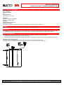
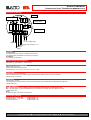
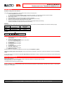
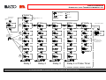
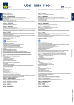
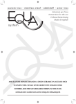
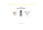
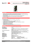
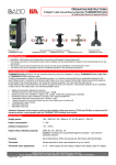
SERVICE MANUAL
HYDROSTATIC LEVEL TRANSMITTER MEMPRO S6.3
Safety Precautions
•
•
•
•
Installation, initial start-up and maintenance may only be performed by trained personnel! All applicable European and national
regulations regarding installation of electrical equipment must be adhered to.
The device may only be connected to supply power which is rated as specified in the technical data!
The device must be disconnected from all sources of power during installation and maintenance work!
The device may only be operated under the conditions specified in the operating instructions!
Functions Description
The MEMPRO S6 back pressure sensor functions in accordance with the pitot-static principle, i.e. current fill-level is derived on the
basis of hydrostatic pressure measured in a tube submerged in the liquid.
The device is adapted to tank dimensions on-site in just a matter of seconds by means of an automatic calibration function.
Four limit value switching points can be assigned to the fill-level range via the setup menu.
All switching points feature adjustable delay time, adjustable hysteresis and selectable NC/NO function.
The MEMPRO S6.3 should be connected to an optionally available vent for tank contents with widely varying temperatures, or for
adhesive or outgassing media. Clock generator control is integrated into the measuring electronics.
Technical Data
Supply power:
24 V DC (9 to 36 V DC is possible)
Connected load:
Approx. 1 VA
Ambient temperature:
-20 to +60° C
Output relays:
3+1 floating limit value contacts
3 with common root
1 floating contact can be selected as a limit value contact,or as a clock generator output (can be switched back and forth between
NC and NO function).
Output relay switching capacity:
250 V AC, 2.0 A / 30 V DC, 1.0 A
Caution: Contacts are not protected against overload – use external protective device!
Terminal housing:
PBT, fibre-glass reinforced, IP 65 per EN 60 529
Terminals:
Screw terminals, max. 1.5 square mm
Measuring cell:
Ceramic diaphragm, with EPDM-sealing *)
*) Attention!:
Use this device only in media, which the EPDM-sensor-sealing is persistent.
In media, which EPDM has only limited persistency please take care that the sensor never contacts the media.
BAMO IER GmbH Pirnaer Straße 24
68309 Mannheim
Tel. +49 (0)621 84224-0 Fax: +49 (0)621 84224-90 . e-Mail: [email protected] Internet: www.IER.de
SU3421.DOC 02/11
1
SERVICE MANUAL
HYDROSTATIC LEVEL TRANSMITTER MEMPRO S6.3
Technical Data (continuation)
Measuring accuracy:
0.5% ± 0.5 digits
Display resolution:
1%
Reset hysteresis:
Adjustable from 1 to 99%
Indicators:
3-digits, 7-segment LED display
4 LEDs = limit value relays
Settings:
Rotary switch and pushbutton
Areator connection:
To connect a hose (such as PVC 4x1mm) or for a air pressure connection with G1/4“-winding
CE Mark
In accordance with low-voltage directive (2006/95/EG), EMC directive (89/336/ECC)
Maintenance
The MEMPRO S6.3 back pressure sensor is maintenance-free if used for its intended purpose. If used in highly adhesive liquids
(e.g. calcium suspensions), the measuring tube or hose must be inspected at regular intervals and cleaned if necessary.
Mechanical Installation
The MEMPRO S6.3 back pressure sensor can be attached to containers and tanks in two different ways:
• With the measuring tube immersed into the tank from above
• With the measuring hose immersed into the tank from above, and with the transducer mounted in close proximity to the tank
Please observe the following points!
The bottom end of the measuring tube or measuring hose corresponds to the 0% fill-level measuring point.
The measuring tube may not make contact with the floor of the tank, nor may it be immersed into bottom sludge!
BAMO IER GmbH Pirnaer Straße 24
68309 Mannheim
Tel. +49 (0)621 84224-0 Fax: +49 (0)621 84224-90 . e-Mail: [email protected] Internet: www.IER.de
SU3421.DOC 02/11
2
SERVICE MANUAL
HYDROSTATIC LEVEL TRANSMITTER MEMPRO S6.3
Electrical Connection
LEDs
Digital Display
± Rotary Switch
Pushbutton
4 32 1 C
+ –
24 V DC Supply Power
Relay 4
Common Root for Relays 1 to 3
Relay 1
Relay 2
Relay 3
Controls
± rotary switch
The desired relay (1 through 4), is selected in menu level 1.
The desired values are selected in menu levels 2 through 6.
Pushbutton:
For selecting the submenus
Output Relays A1 through A4
LED lights up = relay pulled in = contact closed
Limit Value Switching Points
Setting range: 2 to 100%
Relative to the selected 100% fill-level
Default settings: A1 = 80%, A2 = 60%, A3 = 40%, A4* = 20%
Delay Time
Adjustable from 0.1 to 9.9 seconds
After the selected limit value is violated, delay time is allowed to elapse and the relay is then switched.
Default setting: 0.1 seconds
Hysteresis
Setting range: 1 to 99%
The output relay is not switched back until the measured value is fallen short of by the selected percentage value.
Default setting: 1%
NC-NO Selection
NO = normally open = contact is open as long as the actual fill-level is less than the selected limit value.
NC = normally closed = contact is closed as long as the actual fill-level is less than the selected limit value.
Default setting: NO
Note:
All relays are open in the event of power failure.
Overranging Display
Measuring signal > 105% value
Measuring signal < -5% value
No signal from sensor
digital display = пп
digital display = uu
digital display = Err
BAMO IER GmbH Pirnaer Straße 24
68309 Mannheim
Tel. +49 (0)621 84224-0 Fax: +49 (0)621 84224-90 . e-Mail: [email protected] Internet: www.IER.de
SU3421.DOC 02/11
3
SERVICE MANUAL
HYDROSTATIC LEVEL TRANSMITTER MEMPRO S6.3
Clock Generator (* for air supply control)
The aerator hose could be connected to the connection with is under the silver label. The hose connection is suitable for a PVC-hose Ø 4x1 mm.
Purge air pressure should not exceed a level of 2.5 bar.
Aerator Connection
The clock controls are integrated into the electronics, and relay 4 is used to connect, for example, a solenoid valve.
Setting the clock generator:
Set pump-time (on-time) such that air bubbles are discharged from the bottom end of the measuring tube for 3 to 5 seconds (depending upon
the length of the measuring tube and the air supply tube) during each pumping operation!
Off-time:
In the case of liquids which may plug the tube with sediment, pumping should be activated as required.
Measured value drift is reduced by means of frequent pumping if the liquid is subject to temperature fluctuations.
Pumping for a duration of approximately 30 seconds once or twice a day is adequate for most applications. By using the clock Generator for air
supply control it is recommended to use the hold-function
The clock generator is switched on as soon as on and off-time is set to a value of greater than 0.
*) Setting values for limit value relay A4 are rendered inactive as a result.
On-Time
The contact at relay 4 remains closed as long as the selected on-time has not yet elapsed.
Setting range: 1 second to 24 hours
Available setting values:
0*, 1, 2, 5, 10, 30 s
= no decimal point is illuminated
1, 2, 5, 10, 30 min.
= the right decimal point is illuminated
1, 2, 3, 6, 12, 24 hours = the left decimal point is illuminated
Default setting: 0
Off-Time
The contact at relay 4 remains open as long as the selected off-time has not yet elapsed.
setting values same as above
Default setting: 0
Note:
After power failure, the device is rebooted and the program starts with on-time.
If on or off-time is changed during operation, the new on or off-time becomes immediately effective.
Hold-function
In the timer menu there can be activate a hold-function. With this feature it is possible to hold the measure value during the aeration time until the
aeration ends.
Available setting values:
Hof:
hold-function disabled
Hon
hold-function enabled
The hold-function is not working if one of the timer settings set to 0.
BAMO IER GmbH Pirnaer Straße 24
68309 Mannheim
Tel. +49 (0)621 84224-0 Fax: +49 (0)621 84224-90 . e-Mail: [email protected] Internet: www.IER.de
SU3421.DOC 02/11
4
SERVICE MANUAL
HYDROSTATIC LEVEL TRANSMITTER MEMPRO S6.3
Initial Start-Up
Automatic setting of the 100% fill-level:
This 100% level can be adapted to on-site conditions with the help of the setup menu.
1
Install the MEMPRO S6 to the tank.
The measuring tube may not make contact with the floor of the tank, nor may it be immersed into bottom sludge!
2
Fill the tank to a level of between 50 and 100% (it's best to fill the tank to the 100% level).
3
Switch supply power on.
4
Wait approximately 10 seconds until the device is ready for operation.
5
Press and hold the pushbutton for 3 seconds until the digital display starts blinking.
6
Select the actual fill-level percentage with the ± rotary switch.
7
Press the pushbutton once again, or wait for 10 seconds until the digital display stops blinking.
The device calculates the 100% fill-level and save it to memory.
Attention!
The measuring tube or hose may not be shortened indiscriminately! It may not be any shorter than 20% of the maximum measuring range!
Measuring
Minimum Hose /
Measuring Range
Cell Type
Tube Length
0 to 1000 mm WG
200 mm
Type 1
0 to 2500 mm WG
500 mm
Type 2
0 to 4000 mm WG
1000 mm
Type 4
Measuring cell type see serial plate
Example:
MEMPRO
S6
R
1
2
X
L = 1800 m
Setting Limit Value Switching Points A1 through A4
1.
Press the pushbutton once until A1 is displayed.
LED A1 blinks.
2. Press the pushbutton once again.
3. Set limit value switching point 1 with the rotary switch
(0 to 100%, default setting: 80%).
4. Press the pushbutton once again.
5. Set delay time.
6. Press the pushbutton once again.
7. Set hysteresis.
8. Press the pushbutton once again.
9. Select NC or NO function.
10. Press the pushbutton once again.
11. Return to menu level 1.
All other values can be selected and adjusted in the same way (see “Setup Menu” graphic).
Limit value switching points A1 through A4 and the clock generator are selected in menu level 1 (press the pushbutton once) with the ± rotary
switch.
If none of the controls are activated for more than approximately 10 seconds, the display is returned to the current fill-level and the setting values
are saved to memory.
Reset to Default Settings
Switch supply power on.
Within 3 seconds (i.e. during the test routine), press and hold the pushbutton for approximately 5 seconds:
The display counts up: 1, 2, 3, 4 ... 99, Std....
All settings are returned to their default values.
Zero point calibration
Remove the MEMPRO S6 or empty the tank entirely. Press and hold the pushbutton for approximately 3 seconds while in menu “t1” until the LED
display gives “rotating lights”.
BAMO IER GmbH Pirnaer Straße 24
68309 Mannheim
Tel. +49 (0)621 84224-0 Fax: +49 (0)621 84224-90 . e-Mail: [email protected] Internet: www.IER.de
SU3421.DOC 02/11
5
SERVICE MANUAL
HYDROSTATIC LEVEL TRANSMITTER MEMPRO S6.3
Turn Switch
+
LED on
Display of act. Fill Level
%
LEDs
Limit Value Relays A1 ... A4
actuated
A4 A3 A2 A1
100%-Fill Level
A4 A3 A2 A1
Push Button
LED blinks
Basic Adjustment
100%-Fill Level
push
3 Secondes
long
blink
LED off
Select Relay 1
1
Caption
Select Relay 2
Select Relay 3
+
A4 A3 A2 A1
Select Relay 4
+
A4 A3 A2 A1
Select Pulse Timer
+
A4 A3 A2 A1
+
A4 A3 A2 A1
A4 A3 A2 A1
push
3 Seconds
long
push or wait
10 Seconds
Limit Value %
2
Limit Value %
A4 A3 A2 A1
Limit Value %
A4 A3 A2 A1
Limit Value %
A4 A3 A2 A1
OFF-Time
A4 A3 A2 A1
Zero Point
A4 A3 A2 A1
A4 A3 A2 A1
circels
in the Submenues:
Value adjust
with Turn Switch
+
Reset to factory default
3
Delay Time (s)
Delay Time (s)
A4 A3 A2 A1
4
Delay Time (s)
A4 A3 A2 A1
Hysteresis (%)
A4 A3 A2 A1
Hysteresis (%)
A4 A3 A2 A1
A4 A3 A2 A1
Hysteresis (%)
A4 A3 A2 A1
ON-Time
Delay Time (s)
A4 A3 A2 A1
Range:
Sec = no Dec.-point
Min. = right Dec.-point
h = left Dec.-point
Hysteresis (%)
A4 A3 A2 A1
A4 A3 A2 A1
A4 A3 A2 A1
Hold function ON
Hold function OFF
NO/NC Contact
5
NO/NC Contact
A4 A3 A2 A1
A4 A3 A2 A1
Display
back
to Level 1
NO/NC Contact
A4 A3 A2 A1
Display
NO Contact
NC Contact
Relay 1
back
to Level 1
NO/NC Contact
A4 A3 A2 A1
Display
NO Contact
NC Contact
Relay 2
back
to Level 1
Display
NO Contact
NC Contact
Relay 3
back
to Level 1
NO Contact
NC Contact
Relay 4 or Pulse Timer
BAMO IER GmbH Pirnaer Straße 24 68309 Mannheim
Tel. +49 (0)621 84224-0 Fax: +49 (0)621 84224-90 . e-Mail: [email protected] Internet: www.IER.de
SU3421.DOC 02/11
Sheet 6