1
SERVICE MANUAL
MONITOR WITH DVD RECEIVER
SERVICE MANUAL
10
2014
MA601<Rev.001>
KW-V11E, KW-V11EE, KW-V11EU, KW-V11J, KW-V11JW,
KW-V11U, KW-V11UI, KW-V215DBTE, KW-V21BTA,
KW-V21BTE, KW-V21BTEE, KW-V21BTEU, KW-V21BTJ,
KW-V21BTJW, KW-V21BTU, KW-V21BTUI
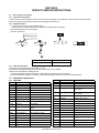
DC cord
(QAM1561-001)
DC cord
(QAM1562-001)
Microphone
(QAN0137-001)
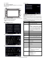
Remote control
(A7A-0006-00)
Mounting assy
(J2C-0006-00)
Car cable
(QAM1419-001)
(3m)
Escutcheon
(B9H-0001-00)
Escutcheon
(B9H-0002-00)
Screw (M5x8)
(QYSTSP5008ZA) x6
Screw (M5x8)
(QYSSSP5008ZA) x6
Lever
(D1A-0007-00) x2
COPYRIGHT © 2014 JVC KENWOOD Corporation
Lead free solder used in the board (material: Sn-Ag-Cu, melting point: 219 Centigrade)
Lead free solder used in the board (material: Sn-Cu, melting point: 230 Centigrade)
COPYRIGHT © 2014 JVC KENWOOD Corporation
No.MA601<Rev.001>
2014/10
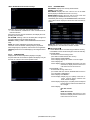
SPECIFICATION
For US
Monitor section
Picture Size (W × H)
6.2 inches (diagonal) wide 137.5 mm × 77.2 mm (5-7/16" × 3-1/16")
Display System
Transparent TN LCD panel
Drive System
TFT active matrix system
Number of Pixels
1 152 000 (800H × 480V × RGB)
Effective Pixels
99.99%
Pixel Arrangement
RGB striped arrangement
Back Lighting
LED
DVD player section
D/A Converter
24 bit
Audio Decoder
Linear PCM/Dolby Digital/MP3/WMA/WAV
Video Decoder
MPEG1/MPEG2/DivX*/JPEG
* Only for KW-V21BT Region 4/KW-V11 Region 4.
Wow & Flutter
Below Measurable Limit
Frequency
Response
96 kHz Sampling
20 Hz to 22 000 Hz
48 kHz Sampling
20 Hz to 22 000 Hz
44.1 kHz Sampling
20 Hz to 20 000 Hz
Total Harmonic Distortion
0.010% (1 kHz)
Signal to Noise Ratio
99 dB (DVD-Video 96 kHz)
Dynamic Range
99 dB (DVD-Video 96 kHz)
Disc Format
DVD-Video/VIDEO-CD/CD-DA
Sampling frequency
44.1 kHz/48 kHz/96 kHz
Quantifying Bit Number
16/20/24 bit
USB interface section
USB Standard
USB 2.0 Full Speed
Compatible Devices
Mass storage class
File System
FAT 12/16/32
Maximum Power Supply Current
DC 5 V
D/A Converter
24 bit
1A
Audio Decoder
MP3/WMA/WAV
Video Decoder
MPEG1/MPEG2/DivX*/JPEG
* Only for KW-V21BT Region 4/KW-V11 Region 4.
Bluetooth section (For KW-V21BT)
Technology
Bluetooth 2.1 + EDR
Frequency
2.402 GHz - 2.480 GHz
Output Power
+4 dBm (MAX), 0 dBm (AVE), Power Class2
Maximum Communication range
Line of sight approx. 10 m (32.8 ft)
Audio Codec
SBC
Profile
HFP (Hands Free Profile) 1.5
SPP (Serial Port Profile) 1.1
SDP (Service Discovery Profile)
A2DP (Advanced Audio Distribution Profile) 1.2
AVRCP (Audio/Video Remote Control Profile) 1.3
OPP (Object Push Profile)
PBAP (Phonebook Access Profile) 1.0
GAP (Generic Access Profile)
(No.MA601<Rev.001>)2/30
FM tuner section
Frequency Range
With channel interval set to 200 kHz: 87.9 MHz to 107.9 MHz
With channel interval set to 50 kHz 87.5 MHz to 108.0 MHz
Usable Sensitivity (S/N: 30 dB Dev 22.5 kHz)
7.2 dBf (0.63 µV/75 Ω)
Quieting Sensitivity (S/N: 46 dB Dev 22.5 kHz)
15.2 dBf (1.58 µV/75 Ω)
Frequency Response (± 3.0 dB)
30 Hz - 15 kHz
Signal to Noise Ratio
68 dB (MONO)
Selectivity (± 400 kHz)
≥ 80 dB
Stereo Separation
40 dB (1 kHz)
AM tuner section
Frequency Range (10 kHz)
530 kHz to 1 700 kHz
Usable Sensitivity
29 dBµ
Video section
Color System of External Video Input
NTSC/PAL
External Video Input Level (RCA/mini jack)
1 Vp-p/ 75 Ω
Video Output Level (RCA jack)
1 Vp-p/ 75 Ω
Audio section
Maximum Power (Front & Rear)
50 W × 4
Full Bandwidth Power (Front & Rear)(4 Ω, 14.4 V, 1% THD) 22 W × 4
Preout Level
4 V/10 kΩ
Preout Impedance
≤ 600 Ω
Speaker Impedance
4Ω-8Ω
Parametric Equalizer (5 Band)
Bass: 63 Hz, 80 Hz, 100 Hz, 125 Hz, ±10 dB
Mid Bass: 200 Hz, 250 Hz, 315 Hz, 400 Hz, ±10 dB
Mid: 0.63 kHz, 0.8 kHz, 1.0 kHz, 1.25 kHz, ±10 dB
Mid High: 2.0 kHz, 2.5 kHz, 3.15 kHz, 4.0 kHz, ±10 dB
High: 6.3 kHz, 8.0 kHz, 10.0 kHz, 12.5 kHz, ±10 dB
General
Operating Voltage
14.4 V (10.5 V - 16 V allowable)
Maximum Current Consumption
10 A
Installation Dimensions (W × H × D)
178 mm × 100 mm × 162 mm (7-1/16” × 3-15/16” × 6-7/16”) (Region 1)
182 mm × 111 mm × 160 mm (7-3/16” × 4-3/8” × 6-5/16”) (Region 4)
Operational Temperature Range
-10°C to +60°C
Weight (Main Unit)
1.6 kg (3.6 lbs) (Region 1)
1.9 kg (4.2 lbs) (Region 4)
• Design and specifications are subject to change without notice.
(No.MA601<Rev.001>)3/30
SPECIFICATION
For Europe
Monitor section
Picture Size (W × H)
6.2 inches (diagonal) wide 137.5 mm × 77.2 mm
Display System
Transparent TN LCD panel
Drive System
TFT active matrix system
Number of Pixels
1 152 000 (800H × 480V × RGB)
Effective Pixels
99.99%
Pixel Arrangement
RGB striped arrangement
Back Lighting
LED
DVD player section
D/A Converter
24 bit
Audio Decoder
Linear PCM/Dolby Digital/MP3/WMA/WAV
Video Decoder
MPEG1/MPEG2/DivX/JPEG
Wow & Flutter
Below Measurable Limit
Frequency Response 96 kHz Sampling
20 Hz - 22,000 Hz
48 kHz Sampling
20 Hz - 22,000 Hz
44.1 kHz Sampling
20 Hz - 20,000 Hz
Total Harmonic Distortion
0.010% (1 kHz)
Signal to Noise Ratio
99 dB (DVD-Video 96 kHz)
Dynamic Range
99 dB (DVD-Video 96 kHz)
Disc Format
DVD-Video/VIDEO-CD/CD-DA
Sampling frequency
44.1 kHz/48 kHz/96 kHz
Quantifying Bit Number
16/20/24 bit
USB interface section
USB Standard
USB 2.0 Full Speed
Compatible Devices
Mass storage class
File System
FAT 12/16/32
Maximum Power Supply Current
DC 5 V
1A
D/A Converter
24 bit
Audio Decoder
MP3/WMA/WAV
Video Decoder
MPEG1/MPEG2/DivX/JPEG
Bluetooth section (For KW-V21BT/KW-V215DBT)
Technology
Bluetooth 2.1 + EDR
Frequency
2.402 GHz - 2.480 GHz
Output Power
+4 dBm (MAX), 0 dBm (AVE), Power Class2
Maximum Communication Range
Line of sight approx. 10 m
Audio Codec
SBC
Profile
HFP (Hands Free Profile) 1.5
SPP (Serial Port Profile) 1.1
SDP (Service Discovery Profile)
A2DP (Advanced Audio Distribution Profile) 1.2
AVRCP (Audio/Video Remote Control Profile) 1.3
OPP (Object Push Profile)
PBAP (Phonebook Access Profile)1.0
GAP (Generic Access Profile)
(No.MA601<Rev.001>)4/30
Digital tuner (DAB) section (For KW-V215DBT)
Frequency Range
L-BAND: 1 452.960 MHz - 1 490.624 MHz
BAND III: 174.928 MHz - 239.200 MHz
Sensitivity
-100 dBm
Signal to Noise Ratio
90 Db
DAB Aerial Connector
Connector type: SMB
Output Voltage: 14.4 V (11 V - 16 V allowable)
Maximum Current: <100 mA
FM tuner section
Frequency Range (50 kHz)
87.5 MHz to 108.0 MHz
Usable Sensitivity (S/N: 30 dB Dev 22.5 kHz)
6.2 dBf (0.56 µV/75 Ω)
Quieting Sensitivity (S/N: 46 dB Dev 22.5 kHz)
15.2 dBf (1.58 µV/75 Ω)
Frequency Response (± 3.0 dB)
30 Hz - 15 kHz
Signal to Noise Ratio
68 dB (MONO)
Selectivity (± 400 kHz)
≥ 80 dB
Stereo Separation
40 dB (1 kHz)
LW tuner section
Frequency Range (9 kHz)
153 kHz to 279 kHz
Usable Sensitivity
45 µV
MW tuner section
Frequency Range (9 kHz)
531 kHz - 1 611 kHz
Usable Sensitivity
28.5 µV
Video section
Color System of External Video Input
NTSC/PAL
External Video Input Level (RCA/mini jack)
1 Vp-p/ 75 Ω
Video Output Level (RCA jack)
1 Vp-p/ 75 Ω
Analog RGB input (Only for EU ver.)
0.7 Vp-p/75 Ω
Audio section
Maximum Power (Front & Rear)
50 W × 4
Full Bandwidth Power (Front & Rear)
(at less than 1% THD))
30 W × 4 (E Ver.)
22 W × 4 (EU Ver.)
Preout Level
4 V/10 k Ω
Preout Impedance
≤ 600 Ω
Speaker Impedance
4Ω-8Ω
Parametric Equalizer (5 Band)
Bass: 63 Hz, 80 Hz, 100 Hz, 125 Hz, ±10 dB
Mid Bass: 200 Hz, 250 Hz, 315 Hz, 400 Hz, ±10 dB
Mid: 0.63 kHz, 0.8 kHz, 1.0 kHz, 1.25 kHz, ±10 dB
Mid High: 2.0 kHz, 2.5 kHz, 3.15 kHz, 4.0 kHz, ±10 dB
High: 6.3 kHz, 8.0 kHz, 10.0 kHz, 12.5 kHz, ±10 dB
General
Operating Voltage
14.4 V (10.5 V - 16 V allowable)
Maximum Current Consumption
10 A
Installation Dimensions (W × H × D)
182 mm × 111 mm × 160 mm (E Ver.)
178 mm × 100 mm × 162 mm (EU Ver.)
Operational Temperature Range
-10°C - +60°C
Weight (Main Unit)
1.9 kg (E Ver.)
1.6 kg (EU Ver.)
• Design and specifications are subject to change without notice.
(No.MA601<Rev.001>)5/30
SPECIFICATION
For ASIA
Monitor section
Picture Size (W × H)
6.2 inches (diagonal) wide 137.5 mm × 77.2 mm
Display System
Transparent TN LCD panel
Drive System
TFT active matrix system
Number of Pixels
1 152 000 (800H × 480V × RGB)
Effective Pixels
99.99%
Pixel Arrangement
RGB striped arrangement
Back Lighting
LED
DVD player section
D/A Converter
24 bit
Audio Decoder
Linear PCM/Dolby Digital/MP3/WMA /WAV
Video Decoder
MPEG1/MPEG2/DivX/JPEG
Wow & Flutter
Below Measurable Limit
Frequency Response 96 kHz Sampling
20 Hz - 22 000 Hz
48 kHz Sampling
20 Hz - 22 000 Hz
44.1 kHz Sampling
20 Hz - 20 000 Hz
Total Harmonic Distortion
0.010% (1 kHz)
Signal to Noise Ratio
99 dB (DVD-Video 96 kHz)
Dynamic Range
99 dB (DVD-Video 96 kHz)
Disc Format
DVD-Video/VIDEO-CD/CD-DA
Sampling frequency
44.1 kHz/48 kHz/96 kHz
Quantifying Bit Number
16/20/24 bit
USB interface section
USB Standard
USB 2.0 High Speed
Compatible Devices
Mass storage class
File System
FAT 12/16/32
Maximum Power Supply Current
DC 5 V
1A
D/A Converter
24 bit
Audio Decoder
MP3/WMA /WAV
Video Decoder
MPEG1/MPEG2/DivX/JPEG
Bluetooth section (For KW-V21BT)
Technology
Bluetooth 2.1 + EDR
Frequency
2.402 GHz - 2.480 GHz
Output Power
+4 dBm (MAX), 0 dBm (AVE), Power Class2
Maximum Communication range
Line of sight approx. 10 m
Audio Codec
SBC
Profile
HFP (Hands Free Profile) 1.5
SPP (Serial Port Profile) 1.1
SDP (Service Discovery Profile)
A2DP (Advanced Audio Distribution Profile) 1.2
AVRCP (Audio/Video Remote Control Profile) 1.3
OPP (Object Push Profile)
PBAP (Phonebook Access Profile) 1.0
GAP (Generic Access Profile)
(No.MA601<Rev.001>)6/30
FM tuner section
Frequency Range (50 kHz)
87.5 MHz to 108.0 MHz
Usable Sensitivity (S/N: 30 dB Dev 22.5 kHz)
6.2 dBf (0.56 µV/75 Ω)
Quieting Sensitivity (S/N: 46 dB Dev 22.5 kHz)
15.2 dBf (1.58 µV/75 Ω)
Frequency Response (± 3.0 dB)
30 Hz - 15 kHz
Signal to Noise Ratio
68 dB (MONO)
Selectivity (± 400 kHz)
≥ 80 dB
Stereo Separation
40 dB (1 kHz)
AM tuner section (For U and A Ver.)
Frequency Range (9 kHz)
531 kHz to 1 611 kHz
Usable Sensitivity
29 dBµ
LW tuner section (For UI Ver.)
Frequency Range (9 kHz)
153 kHz - 279 kHz
Usable Sensitivity
45 dBµ
MW tuner section (For UI Ver.)
Frequency Range (9 kHz)
531 kHz - 1 611 kHz
Usable Sensitivity
28.5 dBµ
Video section
Color System of External Video Input
NTSC/PAL
External Video Input Level (RCA/mini jack)
1 Vp-p/ 75 Ω
Video Output Level (RCA jack)
1 Vp-p/ 75 Ω
Analog RGB input (Only for KW-V21BTU)
0.7 Vp-p/75 Ω
Audio section
Maximum Power (Front & Rear)
50 W × 4
Full Bandwidth Power (Front & Rear)
(at less than 1% THD)
22 W × 4
Preout Level
4 V/10 kΩ
Preout Impedance
≤ 600 Ω
Speaker Impedance
4Ω-8Ω
Parametric Equalizer (5 Band)
Bass: 63 Hz, 80 Hz, 100 Hz, 125 Hz, ±10 dB
Mid Bass: 200 Hz, 250 Hz, 315 Hz, 400 Hz, ±10 dB
Mid: 0.63 kHz, 0.8 kHz, 1.0 kHz, 1.25 kHz, ±10 dB
Mid High: 2.0 kHz, 2.5 kHz, 3.15 kHz, 4.0 kHz, ±10 dB
High: 6.3 kHz, 8.0 kHz, 10.0 kHz, 12.5 kHz, ±10 dB
General
Operating Voltage
14.4 V (10.5 V to 16 V allowable)
Maximum Current Consumption
10 A
Installation Dimensions (W × H × D)
178 mm × 100 mm × 162 mm
Operational Temperature Range
-10°C - +60°C
Weight (Main Unit)
1.6 kg
• Design and specifications are subject to change without notice.
(No.MA601<Rev.001>)7/30
SECTION 1
PRECAUTION
1.1
Safety Precautions
(1) This design of this product contains special hardware and
many circuits and components specially for safety purposes. For continued protection, no changes should be made
to the original design unless authorized in writing by the
manufacturer. Replacement parts must be identical to
those used in the original circuits. Services should be performed by qualified personnel only.
(2) Alterations of the design or circuitry of the product should
not be made. Any design alterations of the product should
not be made. Any design alterations or additions will void
the manufacturers warranty and will further relieve the
manufacture of responsibility for personal injury or property
damage resulting therefrom.
(3) Many electrical and mechanical parts in the products have
special safety-related characteristics. These characteristics are often not evident from visual inspection nor can the
protection afforded by them necessarily be obtained by using replacement components rated for higher voltage, wattage, etc. Replacement parts which have these special
safety characteristics are identified in the Parts List of Service Manual. Electrical components having such features
are identified by shading on the schematics and by ( ) on
the Parts List in the Service Manual. The use of a substitute
replacement which does not have the same safety characteristics as the recommended replacement parts shown in
the Parts List of Service Manual may create shock, fire, or
other hazards.
(4) The leads in the products are routed and dressed with ties,
clamps, tubings, barriers and the like to be separated from
live parts, high temperature parts, moving parts and/or
sharp edges for the prevention of electric shock and fire
hazard. When service is required, the original lead routing
and dress should be observed, and it should be confirmed
that they have been returned to normal, after reassembling.
1.4
Critical parts for safety
In regard with component parts appearing on the silk-screen
printed side (parts side) of the PWB diagrams, the parts that are
printed over with black such as the resistor (
), diode (
)
and ICP (
) or identified by the "
" mark nearby are critical
for safety. When replacing them, be sure to use the parts of the
same type and rating as specified by the manufacturer.
(This regulation dose not Except the J and C version)
1.5
Remote control
The Lithium battery is in danger of explosion if replaced incorrectly. Replace it only with the same or equivalent type.
1.6
Preventing static electricity
Electrostatic discharge (ESD), which occurs when static electricity stored in the body, fabric, etc. is discharged, can destroy the
laser diode in the traverse unit (optical pickup). Take care to prevent this when performing repairs.
1.6.1 Grounding to prevent damage by static electricity
Static electricity in the work area can destroy the optical pickup
(laser diode) in devices such as laser products.
Be careful to use proper grounding in the area where repairs are
being performed.
(1) Ground the workbench
Ground the workbench by laying conductive material (such
as a conductive sheet) or an iron plate over it before placing the traverse unit (optical pickup) on it.
(2) Ground yourself
Use an anti-static wrist strap to release any static electricity
built up in your body.
(caption)
Anti-static wrist strap
1M
1.2
Warning
(1) This equipment has been designed and manufactured to
meet international safety standards.
(2) It is the legal responsibility of the repairer to ensure that
these safety standards are maintained.
(3) Repairs must be made in accordance with the relevant
safety standards.
(4) It is essential that safety critical components are replaced
by approved parts.
(5) If mains voltage selector is provided, check setting for local
voltage.
1.3
Caution
Burrs formed during molding may be left over on some parts
of the chassis.
Therefore, pay attention to such burrs in the case of preforming repair of this system.
Conductive material
(conductive sheet) or iron plate
(3) Handling the optical pickup
• In order to maintain quality during transport and before
installation, both sides of the laser diode on the replacement optical pickup are shorted. After replacement, return the shorted parts to their original condition.
(Refer to the text.)
• Do not use a tester to check the condition of the laser diode in the optical pickup. The tester's internal power
source can easily destroy the laser diode.
(No.MA601<Rev.001>)8/30
1.7
Handling the traverse unit (optical pickup)
(1) Do not subject the traverse unit (optical pickup) to strong shocks, as it is a sensitive, complex unit.
(2) Cut off the shorted part of the flexible cable using nippers, etc. after replacing the optical pickup. For specific details, refer to the
replacement procedure in the text. Remove the anti-static pin when replacing the traverse unit. Be careful not to take too long a
time when attaching it to the connector.
(3) Handle the flexible cable carefully as it may break when subjected to strong force.
(4) I t is not possible to adjust the semi-fixed resistor that adjusts the laser power. Do not turn it.
1.8
Attention when traverse unit is decomposed
*Please refer to "Disassembly method" in the text for the pickup unit.
• Apply solder to the short land sections before the FPC wire is disconnected from the connector on the DVD mecha board. (If the
FPC wire is disconnected without applying solder, the pickup may be destroyed by static electricity.)
• In the assembly, be sure to remove solder from the short land sections after connecting the FPC wire.
Short land section
(No.MA601<Rev.001>)9/30
1.9
Important for laser products
1.CLASS 1 LASER PRODUCT
5.CAUTION : If safety switches malfunction, the laser is able
to function.
2.CAUTION :
(For U.S.A.) Visible and/or invisible class II laser radiation
when open. Do not stare into beam.
(Others) Visible and/or invisible class 1M laser radiation
when open. Do not view directly with optical instruments.
3.CAUTION : Visible and/or invisible laser radiation when
open and inter lock failed or defeated. Avoid direct
exposure to beam.
6.CAUTION : Use of controls, adjustments or performance of
procedures other than those specified here in may result in
hazardous radiation exposure.
!
4.CAUTION : This laser product uses visible and/or invisible
laser radiation and is equipped with safety switches which
prevent emission of radiation when the drawer is open and
the safety interlocks have failed or are defeated. It is
dangerous to defeat the safety switches.
(No.MA601<Rev.001>)10/30
Please use enough caution not to
see the beam directly or touch it
in case of an adjustment or operation
check.
SECTION 2
SPECIFIC SERVICE INSTRUCTIONS
2.1
How to repair a fuse pattern
2.1.1 Purpose of fuse pattern
In order to prevent serious damage on the circuit, fuse pattern is prepared on the GND line of RCA Terminal. This damage may
take due to improper part replacement with a external equipment via RCA line.
2.1.2 Repair Procedure
(1) Check the shorted circuit at the meltdown point.
Need to clean up if the shorted circuit or carbonization happen at the fuse pattern.
(2) Add following parts on the fuse pattern.
(3) Check output level.
Meltdown point
Parts Number
SPEC
F53-0513-08
4A
2.1.3 After finished repair
Due to improper part replacement, this meltdown occurs.
Thus please notice following information when the unit is return to your customer.
Things to be checked before installing the unit.
(1) Check the GND line of external amplifier or other equipment which must connect properly.
(2) Check whether the GND line is not short-circuited with the battery terminal. (do not short-circuit these lines)
2.2
COMPONENTS DESCRIPTION
2.2.1 MAIN PWB
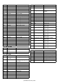
Ref. No. Application / Function Operation / Condition / Compatibility
Ref. No. Application / Function Operation / Condition / Compatibility
IC502
Voltage detect IC
Reset signal generate at 2.4V
IC1
System DC Regulator IC
IC503
EEPROM
Memory
IC711
AND Logic IC
Navi(SXI) TX 3.3V→
5.0V convert
IC721
AND Logic IC
Navi(SXI) RX 5.0V→
3.3V convert
IC801
MCU IC
DAB control IC
Q31
Transistor
SURGE_DET control
Q32
Transistor
SURGE_DET control
Q33
Transistor
SURGE_DET control
Q34
Transistor
SURGE_DET control
Q35
Transistor
BU_DET control
Transistor
BU_DET control
Regulator
IC111
Regulator
D3.3V DCDC convertor IC
IC131
Regulator
Mecha8V DCDC convertor IC
IC151
Regulator
22V/-20V DCDC convertor IC
IC171
Regulator
D5.8V DCDC convertor IC
IC172
Hi-side SW
Current limit
IC173
Regulator
For USB5V Regulator IC
IC174
Regulator
For Mecha5V Regulator IC
IC201
Power IC
Power AMP
IC301
Electric Vol IC
Audio Vol Control, Audio Signal
Select
IC341
Isolation Amp
For iPod-V
Q36
IC351
Video selector IC
Video selector to LCD
Q37
Transistor
BU_DET control
Transistor
ACC_DET control
IC361
Video selector IC
Video selector to VOUT
Q41
IC362
Video buffer
VOUT Video driver with LPF
Q42
Transistor
ACC_DET control
Transistor
ACC_DET control
IC401
TUNER IC
TUNER IC
Q43
IC471
Regulator
For CD5V Regulator IC
Q51
Transistor
ILUMI control
System control IC
Q91
Transistor
Parking control
IC501
MCU IC
(No.MA601<Rev.001>)11/30
Ref. No. Application / Function Operation / Condition / Compatibility
Ref. No. Application / Function Operation / Condition / Compatibility
Q92
Transistor
Parking control
Q206
SW
KEY_LED power control
Q93
Transistor
Parking control
Q261
SW (KW-V only)
Q94
Transistor
Reverse control
KEY LED Constant current
circuit
Q101
SW FET
SW14V ON/OFF
Q302
Voltage Drop
Q102
Transistor
SW14V control
Voltage Drop for input of 9.2V
Regulator
Q105
Transistor
SW14V control
Q305
Voltage Drop
Voltage Drop for 18V
Q151
SW FET
DCDC SW FET (22V, -22V)
Q306
SW
Switch for 18V
Q252
Transistor
PRE_OUT_Mute control
Q261
Transistor
PRE_OUT_Mute
Q262
Transistor
PRE_OUT_Mute
Q263
Transistor
PRE_OUT_Mute
Q264
Transistor
PRE_OUT_Mute
Q265
Transistor
PRE_OUT_Mute
Q511
Transistor
RESET MUTE control
Q512
Transistor
RESET MUTE
Q513
Transistor
DET MUTE
Q521
Transistor
KEY IN DET
Q591
Transistor
SW3.3V control
Q592
Transistor
SW3.3V control
Q601
Transistor
SI control
Q611
Transistor
TOUCH control
Q612
Transistor
TOUCH control
Q613
Transistor
TOUCH control
Q614
Transistor
TOUCH control
Q761
MOS FET
STREMO control
Q762
Transistor
STREMO control
Q771
MOS FET
STREMO control
2.2.2 SWITCH PWB
Ref. No. Application / Function Operation / Condition / Compatibility
IC101
Remote control
module
Remote control sensor
Q102
buffer
LED buffer
Ref. No. Application / Function Operation / Condition / Compatibility
IC101
Chroma gamma
T/C Scaller
Chroma gamma T/C Scaller
IC102
128Mbit SDRAM IC
SDRAM for Image signal
preservation
IC103
64Mbit FLASH ROM FLASH ROM for MN103SH23
IC104
64Mbit FLASH ROM FLASH ROM for MN103SH23
Regulator
1.2V Regulator IC
IC301
Regulator
9.2V Regulator IC
IC302
OP-AMP X 2
VCOM AMP
Q101
SW
NAVI vsync control
SW
Switch for 18V
Q308
Voltage Drop
Voltage Drop for -6V
Q309
Voltage Drop
Voltage Drop for -6V
Q310
SW
Switch for -6V
Q311
SW
Switch for -6V
Q302
SW
Switch for -6V
Q401
LCD Backlight lighting LCD Backlight Constant
current circuit
Q402
LCD Backlight lighting LCD Backlight Constant
current circuit
Q403
LCD Backlight lighting LCD Backlight Constant
current circuit
Q404
LCD Backlight lighting LCD Backlight Constant
current circuit
Q405
LCD Backlight lighting LCD Backlight Constant
current circuit
Q406
LCD Backlight lighting LCD Backlight Constant
current circuit
Q407
LCD Backlight lighting LCD Backlight Constant
current circuit
Q408
LCD Backlight lighting LCD Backlight Constant
current circuit
Q409
LCD Backlight lighting LCD Backlight Constant
current circuit
2.2.4 DAB TUNER PWB
Ref. No. Application / Function Operation / Condition / Compatibility
IC1
2.2.3 VIDEO PWB
IC105
Q307
Q201
buffer
VIDEO buffer
Q202
buffer
VIDEO buffer
Q203
buffer
VIDEO buffer
Q204
buffer
VIDEO buffer
Q205
SW
KEY_LED power control
FM/AM Tuner IC
FM/AM Tuner & HD blending
IC2
LOW Tuner IC
Low IF Tuner
IC3
DAB decoder
DAB signal processing
IC4
Serial Flash memory Boot code storage for Si4613
IC5
Regulator
1.2V Regulator IC
IC6
Regulator
1.8V Regulator IC
IC7
Regulator
1.8V Regulator IC
(No.MA601<Rev.001>)12/30
SECTION 3
DISASSEMBLY
3.1
Main body
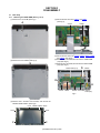
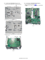
3.1.1 Removing the VIDEO PWB (See Fig.1 to 5)
(1) Remove the 1 screw A. (See Fig.1)
(4) Disconnect the wires from CN201 and CN801.
(See Fig.4)
A
CN201
CN801
Fig.4
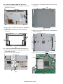
(5) Disconnect the wires from CN202, CN203, CN301, CN401
and CN402. (See Fig.5)
(6) Remove the 4 screws D, and remove the VIDEO PWB
(1/2). (See Fig.5)
(7) Remove the 2 screws E, and remove the VIDEO PWB
(2/2). (See Fig.5)
Fig.1
(2) Remove the 2 screws B. (See Fig.2)
B
VIDEO PWB (1/2)
D
CN202
D
E
CN203 CN301
Fig.2
(3) Remove the 2 screws C and 3 hooks, and remove the
FRONT PANEL ASS'Y. (See Fig.3)
Hook
Hook
FRONT PANEL ASS'Y
Hook
C
C
Fig.3
(No.MA601<Rev.001>)13/30
CN402 CN401 D VIDEO
PWB (2/2)
Fig.5
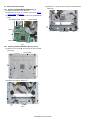
3.1.2 Removing the SWITCH PWB. (See Fig.6 and 7)
(1) Remove the 2 screws F and 1 screw G, and remove the
BRACKET. (See Fig.6)
G
(3) Remove the 2 screws M, and remove the TOP PLATE.
(See Fig.9)
M
BRACKET
F
F
Fig.6
(2) Remove the 4 screws H, and remove the GUIDE(L/R).
(See Fig.7)
(3) Remove SWITCH PWB(1/2) and SWITCH PWB(2/2).
(See Fig.7)
SWITCH PWB (1/2)
TOP PLATE
Fig.9
(4) Remove the 4 screws N, and remove the DVD MECHA
ASS'Y. (See Fig.10)
SWITCH PWB (2/2)
DVD MECHA ASS'Y
H
H
N
N
GUIDE
GUIDE
Fig.7
3.1.3 Removing the DVD MECHA ASS'Y (See Fig.8 to 11)
(1) Remove the 3 screws J and 2 screws K, and remove the
HEATSINK. (See Fig.8)
(2) Remove the 2 screws L. (See Fig.8)
J
L
HEATSINK
Fig.10
(5) Disconnect the FFC wire from CN401. (See Fig.11)
L
CN401
K
J
Fig.8
Fig.11
(No.MA601<Rev.001>)14/30
3.1.4 Removing the MAIN PWB (See Fig.12 to 14)
(1) Remove the 2 screws P and 1 screw Q. (See Fig.12)
P
3.1.5 Removing the DAUGHTER PWB (See Fig.15)
(1) Disconnect the FFC wire from CN501.
(2) Remove the 2 screws T, and remove the DAUGHTER
PWB.
CN501
Q
Fig.12
(2) Remove the 1 screw R. (See Fig.13)
T
DAUGHTER PWB
Fig.15
R
Fig.13
(3) Remove the 2 screws S, and remove the MAIN PWB.
(See Fig.14)
MAIN PWB
S
Fig.14
(No.MA601<Rev.001>)15/30
3.2
DVD mechanism assembly
3.2.1 Removing the DVD MECHA PWB (See Fig.1)
(1) Solder the short land on the PICK UP.
(2) Disconnect the FPC or Connector wires from CN101,
CN201, CN202 and CN301.
(3) Remove the 2 screws A and remove the DVD MECHA
PWB.
DVD MECHA PWB CN101
(3) Remove the 1 screw C, and remove the ROLLER ASSY.
(See Fig.4)
SHORT RAND
C
CN301
ROLLER ASSY
Fig.4
A
CN202
CN201
Fig.1
3.2.2 Removing the ROLLER ASSY. (See Fig.2 and 3)
(1) Remove the 4 screws B, and remove the TOP COVER.
(See Fig.2)
TOP COVER
B
B
Fig.2
(2) Remove the 2 springs. (See Fig.3)
SPRING
Fig.3
(No.MA601<Rev.001>)16/30
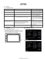
SECTION 4
ADJUSTMENT
4.1
Test Mode
4.1.1 List of special modes
Mode name
Description
Key used
TUNER span switching
Switches TUNER frequency step/span.
Press and hold the [DISP] key and
[EJECT] key, and press the [RESET] key.
Memory clear
Clears the backup memory and installer memory.
INITIALIZE inside the Setup menu
(INITIALIZE in the service mode)
SS mode
Special service mode that is entered from the production Press and hold the [EQ] key and [DISP]
mode.
key, and press the [RESET] key.
Service mode
Mode used by engineers or servicing personnel.
Note: Confirm that the Bluetooth is not connected.
While pressing the [EQ] key, touch upper left corner of the touch panel within
0.5 seconds, and then touch upper
right corner of the touch panel within 2
seconds.
Opening Customize Mode
(and) Setting Rewrite mode
Mode used by sales and retail.
Overwrites the start-up screen with DISC/USB.
Overwrites the initial settings after factory shipment.
Example: DEMO=OFF, NAVI=ON, etc.
While pressing the [EQ] key,
lower left corner of the touch
within 0.5 seconds, and then
lower right corner of the touch
within 2 seconds.
Force EJECT
Mode to use when the DISC cannot be ejected.
Press and hold the EJECT key for 10
seconds.
4.2
Service Mode
4.2.1 Switching to service mode
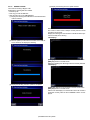
Note: Confirm that the Bluetooth is not connected.
• While pressing the [EQ] key (1), touch upper left corner (2) of
the touch panel within 0.5 seconds, and then touch upper right
corner (3) of the touch panel within 2 seconds.
(2)
4.2.2 Display specifications
Service Mode Page1 <DAB MODEL>
(3)
(1)
Service Mode Page1 <Except DAB MODEL>
(No.MA601<Rev.001>)17/30
touch
panel
touch
panel
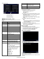
Service Mode Page2
Text
DATA4 ****
Description
Display of DEMO image version
(Commercially=”1000”)
DAB ****/******** Display of DAB module version
HDR ********
Display of HD-Radio module version
[NEXT] key: Switch from Page 1 → Page 2.
[PREV] key: Switch from Page 2 → Page 1.
[EXIT] key: Exit the Service Mode and return to the normal
screen.
Text
SYS *.*** ****
Description
Display of system controller version and JVM
number
APP *.*.***
Display of APP u-controller + design data
version
DATA ****
DISC ****
Display of Font data version
Display of DISC mecha module version
Macro ****
DivX ****
Display of Macrovision version
Display of DviX version
BT ****
Span *
Type
Display of BT module Firmware version
Display of Span selection status for Tuner
(displayed as NA or SA or EU or ASIA or BR
or TN or JP)
Destination information
Model
DISC-Area
Model Information
DISC mecha module destination information
Region
S.NO
Region code
Serial number
DATA1 ****
Display of opening data's version
(Commercially=”1000”, DOP=”DOP”)
DATA2 ****
Display of wallpaper data's version
(Commercially: ”1000”, DOP: ”DOP”)
DATA3 ****
Display of steering remote control threshold
version
Displays the version number when threshold
data is written using USB.
For DOP models, display as follows as the
fixed value is retained from the beginning.
Commercially support model: “0001”
Commercially non support model: “-”
HONDA: “KC”
MAZDA: “KF”
MITSUBISHI: “KG”
ISUZU: “KJ
NISSAN1: “KS1”
NISSAN2 “KS2”
TOYOTA: “KL”
4.2.2.1 INITIALIZE ALL
Process (1) to (4) in sequence.
(1) Initialization of system controller EEPROM
Backup memory, user profiles 1 to 3
Tuner Area setting
Error history
(2) Initialization of DISC module EEPROM (Initialize to normal)
Send [Arg0: 9C, Arg1: 06, Arg2: 00] (initialize EEPROM to
normal) to DISC module
Receive [Arg0: AA Arg1: 01] from DISC module
Receive [Arg0: AA Arg1: 09 Arg2: ** Arg3: **] from DISC
module
(3) Initialization of Bluetooth module EEPROM
Note:
Before performing Initialize All, turn off BT pairing mode
and voice-recognition mode. Failure to do so will result in
error during initialization.
(4) Initialization of user-captured wallpaper area
Clear the APP u-controller F.ROM user-capture area and
reset to the initial state (all black).
Data not cleared
• Monitor adjustment data (panel Flash ROM)
• Touch panel adjustment data / Tuner adjustment data / Tuner span information / serial no. (Syscom EEPROM)
• No. of power-on counts (Syscom EEPROM)
• No. of eject counts (DISC mecha EEPROM)
<While executing INITIALIZE>
<When INITIALIZE completed normally>
Below screen is retained and normal screen is not displayed.
• [BACK] / [EXIT] keys prohibited
• All keys including hard keys and remote controller keys are
prohibited.
(No.MA601<Rev.001>)18/30
<When INITIALIZE terminated abnormally>
4.2.2.3 RUNNING MODE
DVD MODE5: Displays the currently selected mode
COUNT: Counter display
DVD ERROR: Displays the error code for error in the DISC
mecha (display as 000000 when there is no error)
DOOR ERROR: Displays the error code for error in the door
mecha (display as 000000 when there is no error)
*Immediately after moving to the RUNNING MODE, hide the display of all the above. Display the above items after an item is selected.
Determine error in each block of SYSTEM/ DISC/ BT.
• In case of Bluetooth, Initialize Error is also considered as abnormal termination
Discontinue process once NG is detected, and display the corresponding error as follows.
NG SYSTEM: Clearing of the unit set EEP (APP management
and SYS management) terminated abnormally
NG DISC: Clearing of DISC module EEPROM terminated abnormally.
NG BT: BT module initialization terminated abnormally.
The below screen is retained until the [EXIT] key is pressed.
When the [EXIT] key is pressed, normal screen is brought back.
[EXIT] key: Return to the normal display by canceling the service
mode.
4.2.2.2 TEMPERATURE
Displays DISC module temperature (displays in 3 digits).
Acquires data from the module and updates the display every 30
seconds, as is done in the normal operation mode.
[BACK] key: Goes back to the service mode. *Only valid before
selecting an item. Not valid after a selection is made.
Mode Cancel Key
• DOOR MODE can be canceled using the EJECT hard key.
• DVD MODE can be canceled using the Power Off hard key.
(1) DOOR MODE
Execute Door mecha running mode 1.
(Not valid for models without door mecha.)
2th line display: DOOR MODE 1
3th line display: Display the number of runs in 6 digits.
4th line display: Nil
5th line display: Display as "000000" when there is no door
mecha error, display the door mecha error
code when an error has occurred.
(2) DVD MODE 1 to 6
Execute DVD running mode 1 to 6
(For models with door mecha, OPEN/CLOSE the door in
sync with DISC LOAD/EJECT.)
2th line display: DVD MODE 1
3rd line display: Display Arg 5,6,7 (BCD) of the "Unit request" (running status) received from
DISC module in 6 digits.
4th line display: Display Arg 2,3,4 (HEX) of the Unit request
(running status) received from DISC module in 6 digits.
5th line display:
<No door mecha>
Nil
<With door mecha>
Display as "000000" when there is no door
mecha error. Display the door mecha error
code in the event of an error.
(No.MA601<Rev.001>)19/30
4.2.2.4 DVD CHECK MODE
When this mode is selected, reset DISC module and restart in
Check Mode. (Specify "Check Mode On" in the startup mode for
0x94 command.)
After restarting in Check Mode, transit to DVD CHECK MODE
screen.
Directly touch the item to select the operation.
NORMAL PLAY: Displays the currently selected item
XXXX XXXX: Displays the data acquired from the mecha module
(4 bytes) as it is.
(6) DVDx1 JITTER MODE
Process test item [6] of the check mode specification
2nd line display: DVDx1 JITTER MODE
3rd line display: Display Arg 2,3,4,5 (HEX) of the command
received from the module, in the following format.
X X X X
X X X X
Arg2 Arg3
Arg4 Arg5
(7) SEARCH & JITTER
Process test item [10] of the check mode specification
2nd line display: SEARCH & JITTER
3rd line display: Display Arg 2,3,4,5 (HEX) of the command
received from the module, in the following format.
X X X X
Arg2 Arg3
X X X X
Arg4 Arg5
(8) MONITOR
Process test item [11] of the check mode specification
2nd line display: MONITOR
3rd line display: Display Arg 2,3,4,5 (HEX) of the command
received from the module, in the following format.
• Immediately after moving to the DVD CHECK MODE, hide the
display of all the above. Display the top 2 lines after an item is
selected.
• DVD CHECK MODE is cleared by power OFF (Clear by ACC
OFF/ BATTERY OFF/Detach).
(1) NORMAL PLAY
Process test item [1] of the check mode specification
2nd line display: NORMAL PLAY
3rd line display: Display Arg 2,3,4,5 (HEX) of the command
received from the module, in the following format.
X X X X
X X X X
Arg2 Arg3
Arg4 Arg5
(2) EF OUT-TRACKING OFF
Process test item [2] of the check mode specification
2nd line display: EF OUT-TRACKING OFF
3rd line display: Nil
(3) EF IN-TRACKING OFF
Process test item [3] of the check mode specification
2nd line display: EF IN-TRACKING OFF
3rd line display: Nil
(4) CD-LASER ON
Process test item [4] of the check mode specification
2nd line display: CD-LASER ON
3rd line display: Display Arg 2,3,4,5 (HEX) of the command
received from the module, in the following format.
X X X X
X X X X
Arg2 Arg3
Arg4 Arg5
(9) DVDx1 PLAY
Process test item [12] of the check mode specification
2nd line display: DVDx1 PLAY
3rd line display: Display Arg 2,3,4,5 (HEX) of the command
received from the module, in the following format.
X X X X
Arg2 Arg3
(10) STOP
Process test item [13] of the check mode specification
2nd line display: STOP
3rd line display: Nil
(11) EJECT
Process test item [14] of the check mode specification
2nd line display: EJECT
3rd line display: Nil
(12) LOAD
Process test item [15] of the check mode specification
2nd line display: LOAD
3rd line display: Nil
(13) SLEEP
Process test item [16] of the check mode specification
2nd line display: SLEEP
3rd line display: Nil
X X X X
X X X X
Arg2 Arg3
Arg4 Arg5
(5) DVD-LASER ON
Process test item [5] of the check mode specification
2nd line display: DVD-LASER ON
3rd line display: Display Arg 2,3,4,5 (HEX) of the command
received from the module, in the following format.
X X X X
Arg2 Arg3
X X X X
Arg4 Arg5
X X X X
Arg4 Arg5
(No.MA601<Rev.001>)20/30
4.2.2.5
ERROR/DIAG DATA
4.2.2.9 BT MICROPHONE TEST
The mode for confirming the normal operation of BT audio circuit
by inputting audio from MIC and outputting from the speaker.
• Switch the audio selector to Bluetooth.
• Send Bluetooth Loop back START command to TCC.
• Send to TCC the command for setting Mic Gain, set at Gain 2
(fixed).
<While executing MICROPHONE TEST>
Retain the above screen until [EXIT] key or [BACK] key is
pressed.
[BACK] key: Goes back to the Service Mode
(1) DVD ERROR (DISC module error history)
By DISC module communication, acquire total error count,
the most recent 3 errors, initial 5 errors, and display them.
(2) MECHA ERROR (door mechanism error history)
Read total error count, the most recent 3 errors, initial 5 errors from EEPROM, and display them.
(3) DC1 / DC2 (DC offset error history)
Read whether or not there is a DC1 error, and DC2 error
count from EEPROM, and display them.
(4) Power Detected(********)
Read the number of times power supply was turned ON
from EEPROM, and display the count.
Display as follows according to the counter value.
a) "Power Detected (counter value)" when counter value is 2 or higher
b) "No Detection(1)" when counter value is 1
c) "Detection Cleared!" when counter value is 0
(5) DISC EJECT **** times
By DISC module communication, acquire DISC EJECT
count and display it.
(6) [DVD ERROR/DISC EJECT CLR] key
Clears the DVD ERROR history and DISC EJECT count.
(Sends to DISC module EEPROM initialization command
(also initializes error history).)
→Goes back to the Service Mode
(7) [MECHA ERROR CLR] key
Clears the door mechanism error history.
→Goes back to the Service Mode
(8) [DC ERROR CLR] key
Clears the DC1/2 error history.
→Goes back to the Service Mode
(9) [Power History CLR] key (Key with no character)
Clears the number of times power supply was turned ON.
→Goes back to the Service Mode
[EXIT] key or [BACK] key: Transition to the completed screen.
<MICROPHONE TEST completed>
This mode can be cleared only by turning the power OFF.
• [BACK] / [EXIT] keys prohibited
4.2.2.6 RDS TEST MODE
Screen for checking the setting and information for Radio Data
System test mode.
4.2.2.7 HD/DAB TEST
Screen for checking the setting and information for HD/DAB test
mode.
*The same key is used for DAB TEST and HD TEST; the key
TOP display will be automatically switched on the corresponding
models.
4.2.2.8 NR / EC
Mode for setting the speech quality of the hands-free microphone.
(No.MA601<Rev.001>)21/30
4.2.2.10 FIRM UPDATE MODE
4.2.2.11 STEERING REMOTE DEVELOPMENT
[BACK] key: Goes back to the Service Mode
[BACK] key: Goes back to the Service Mode
(1) [Bluetooth]/[APPCOM]/[SYSCOM]/[DAB] key
Perform Update when a USB device containing the Update
data is inserted.
<Display during Update (Image)>
<Update Complete Display (Image)>
4.2.2.12 SXM CODE CLR
Mode for clearing the Sirius XM parental code
Press the KEY to start the clearing process. The screen switches
to the following view.
After the clearing process is complete, switch to the following
screen.
[BACK] key: Returns to the SS mode or service mode screen
[EXIT] key: Exits the SS mode or service mode
(No.MA601<Rev.001>)22/30
4.3
SS mode
SS Mode Page3
4.3.1 Switching to SS mode
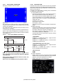
Press and hold the [EQ] key and [DISP] key (1), and press the
[RESET] key (2).
(2)
(1)
(1)
4.3.2 Clearing the SS mode
Performing one of the following operations cancels the production mode and restores the normal mode.
• Power off by battery (backup) OFF
• Reset
4.3.3 Display specifications
SS Mode Page1
SS Mode Page2 <DAB MODEL>
[NEXT] key: Switch from Page 1 → Page 2.
[PREV] key: Switch from Page 2 → Page 1.
[EXIT] key: Exit the SS Mode and return to the normal screen.
When any of the above SS mode screens is displayed (Page 1/
3, 2/3, 3/3), set the audio selector to MUTE (equivalent to Standby source).
Upon exiting the SS mode to return to the normal mode, restore
the audio selector to the original source.
Text
Description
SYS x.***
Display of system controller version.
x:0(1S), 1(2S), 2(PP), 3(MP)
APP x.y.zzz
Display of system controller + design data
version
x:0 (release not been approved), 1 (release
approved), y: rounded up by the official release, zzz: revision number managed by the
SVN ("10" won't be expressed as "010")
* The version system of DDX and that of KWV are common.
DATA ****
Display of font data version.
DISC ****
Display of DISC mecha module version.
DivX ****
Display of DivX version.
BT ****
Display of BT module firmware version.
Span *
Display of Tuner's span selection status (NA
or SA or EU or ASIA or BR or TN or JP).
Type
Display of destination information.
Model
Display of model information.
DISC-AREA
Display of area information of the DISC
mecha module.
reg.
Display of region code.
HDR ********
Display of HD-Radio module version (HDR
model only)
DAB ****/********
Display of DAB module version (DAB model
only)
SS Mode Page2 <Except DAB MODEL>
OK Display for All When APP & DATA CHKSUM is executed,
Items Above
check against data in USB, and display OK
or NG.
*Not displayed if it is not executed.
*Display NG in red.
MON: Y or N
(No.MA601<Rev.001>)23/30
Display of status of monitor adjustment by
production line.
Y: adjustment complete
N: not adjusted.
*Display NG in red.
Text
Description
TOU: Y or N
Display of status of touch panel adjustment
by production line.
Y: adjustment complete
N: not adjusted.
*Display NG in red.
SUM ********
Display of APP micro-controller program area's sum and check sum results. Check sum
OK or NG.
*Display NG in red.
SUM ********
Display of APP micro-controller design data
area's sum and check sum results. Check
sum OK or NG.
*Display NG in red.
S.NO
Display of serial number.
No entry: - - - - - Model without serial no.: None
Indicate "- - - - - -" in red.
Models without serial no. are as follows.
Destinations: J, JW, E, EE, A
DATA1 ****
Displays the opening data version.
SUM ********
Display of opening data area's sum and
check sum results. Check sum OK or NG.
*Display NG in red.
DATA2 ****
Displays the wallpaper data version.
SUM ********
Display of opening data area's sum and
check sum results. Check sum OK or NG.
*Display NG in red.
DATA3 ****
Displays the steering remote control threshold version.Displays the version number
when threshold data is written using USB.
For DOP models, display as follows as the
value is fixed from the beginning.
HONDA: KC
MAZDA: KF
MITSUBISHI: KG
ISUZU: KJ
NISSAN1: KS1
NISSAN2: KS2
TOYOTA: KL
DATA4 ****
Display of DEMO image version
(Commercially=”1000”)
SUM ********
Display of opening data area's sum and
check sum results. Check sum OK or NG.
*Display NG in red.
4.3.3.1 INITIALIZE ALL
Same as service mode.
4.3.3.2 S/N WRITE & RGB(SXM) TERMINAL CHK
Mode for entering the serial number.
*This will not be displayed for models without the NAVI and Sxi
terminals.
4.3.3.3 MONITOR ADJUSTMENT MODE
Mode for adjusting the image quality on the production line.
Display the following.
In this case, regardless of the current source, set Video selector
to R-CAM, and display the external input video in the background.
(This is for adjustment by inputting composite signal in a white
image from an external pattern generator.)
Restore the Video selector to the original state when exiting this
adjustment mode.
• As adjustment is performed while pressing the sensor of the
measuring instrument against the center of the monitor, display the adjustment button and STORE button on the Aright
side of the screen.
Adjustment items are only 3 items, Drive R/G/B only, and pressing the STORE button writes the adjustment value into F. ROM.
4.3.3.4 BT MICROPHONE TEST
Same as service mode.
(No.MA601<Rev.001>)24/30
4.3.3.5 REGION CHANGE
The mode for rewriting a Region Code.
Download the rewriting data from CUSiS.
• Extracts zip file.
• Find Vup_info.cds and ZZZ files.
• Write the 2 files to root of USB MEMORY.
(1) Display the following if the USB device is inserted when this
mode is selected.
(4) Display the following when the update is failed.
4.3.3.6 BT DEVICE SEARCH MODE
The mode to confirm if the Telechips module performs normal
operations electronically.
Display the following if a communication of the BT module is performed normally when entering
<OK display>
(2) Start the update process after the insertion of the USB device is detected, and display the following.
[BACK] key: Returns to the SS mode or service mode screen
[EXIT] key: Return to normal screen
Display the following if the BT dongle cannot be correctly detected.
<NG display>
(3) Display the following when the update is completed.
[BACK] key: Returns to the SS mode or service mode screen
[EXIT] key: Return to normal screen
Switch to the OK display if a communication to the BT module is
performed normally while the above ERROR screens are displayed.
(No.MA601<Rev.001>)25/30
4.3.3.7 TOUCH PANEL CALIBRATION
Define the coordinates used in this sheet.
4.3.3.7.1
Touch adjustment (TOUCH ADJUST)
The 4 points on the screen, P1 (X1,Y1), P2 (X2,Y2), P3 (X3,Y3),
P4 (X4,Y4) are the coordinate values (voltage values) actually
read by touch adjustment.
The points shown on the adjustment screen have 2 dots, one for
X and one for Y coordinate.
In normal mode touch adjustment, P2 and P4 coordinates are acquired. In test mode touch adjustment, coordinates of P1 to P4
are acquired (The reference point is lower left, whose coordinate
value shall be (1,1).
4.3.3.7.2
Touch panel ADJUST specifications
u-com default condition
In-factory adjustment
Test mode
Readjustment
Factory default condition
User adjustment
Touch panel reset
User
Readjustment
Readjustment
User-adjusted condition
Note 1: In normal mode touch adjustment, “RESET” on the
touch adjustment screen resumes the data touch adjusted
in the test mode.
Note2: Factory default adjustment should be cleared, and
re-adjustment is enabled.
4.3.3.8 VER/CHECK SUM
Performs check on the version number of each micro-controller/
data and the SUM value of the APP program area/DATA area.
Select this item after inserting a USB device containing the check
data for all of the above.
For details on the data format for checking, refer to "About Data
for VER/CHECK SUM Checking".
(1) Version Number Check
Determines whether the version number retained within the
set is consistent with that read from the USB device.
If the version number is consistent, display "OK" to the left
of the version display. If it is not consistent, display "NG".
Perform version check on all items on SS Mode Page2/3
marked with "OK".
Consistent: “OK: 1.00.00”
Not consistent: “NG: 1.00.00”
Not checked: “1.00.00”
*Each time this item is selected, the latest result will be displayed.
(2) SUM Value Check
Calculate the SUM value for each of the APP program area
and DATA area, and determine whether they are consistent with the SUM value read from the USB device.
If the value is consistent, display OK + SUM value. If it is
not consistent, display NG + SUM value.
*Exclude DATA area for DOP (DATA1, DATA2, DATA3)
from SUM calculation.
<CHKSUM OK>
ASUM OK ********(SUM value 4 bytes) ← Upper line shows
CHKSUM result of program area
DSUM OK ********(SUM value 4 bytes) ← Lower line shows
CHKSUM result of DATA area
<CHKSUM NG (NG only for Data Area)>
ASUM OK ********(SUM value 4 bytes) ← Upper line shows
CHKSUM result of program area
DSUM NG ********(SUM value 4 bytes) ← Lower line
shows CHKSUM result of DATA area
<Not Calculated>
ASUM
DSUM
(3) TOTAL Assessment
Display TOTAL as OK only if all version checks and SUM
values are OK, and all monitor adjustment, touch panel adjustment, and S meter adjustment are complete.
Display as NG if any one of these is NG.
Note3: Users cannot RESET the factory default condition.
(No.MA601<Rev.001>)26/30
Line
No
(4) When USB device is not inserted
Display the following if a USB device is not detected when
this item is selected.
4.3.3.8.1
About Data for VER/CHECK SUM Checking
VER/CHECK SUM is performed by reading out the checking
data from the USB via the DISC mecha.
Data transfer from the DISC mecha employs the same mechanism as APP/SYS Firm UP, i.e., system controller UPGRADE
operation.
Therefore, the two files below are stored in the USB memory.
• ver_check.txt ← Data for checking
• VUP_info.cds ← Information data for system controller UPGRADE
(1) Data Format for Checking
* Formed from the 20 lines of text data below.
Line
No
Data Content
Description
1
Version Check
Header
2
[MODEL]DDX4R
Model name. Rewritten
according to the model.
3
[TYPE]K
Destination code. Rewritten
according to the shipment
destination.
4
[SPAN]NA
SPAN information. Rewritten
according to the initial span
setting value.
5
[APP]1.0.0
APP micro-controller version
No. (program + design)
6
[DATA]0001
Data version no. (font data)
7
[DATA1]V0001
DATA1 version No.
(opening data)
8
[DATA2]V1111
DATA2 version No.
(wallpaper data)
9
[DATA3]0001
DATA3 version No.
(ST.Remo threshold data)
Data Content
Description
10 [DATA4]1000
DATA3 version No.
(DEMO image data)
11 [SYS]3.000
SYSCOM version No.
12 [DISC_A]JC
DISC mecha destination
code. Rewritten according to
the shipment destination.
13 [DISC_R]1
DISC mecha region No.
Rewritten according to the
shipment destination.
14 [DISC_V]0010
DISC mecha version No.
(program)
15 [DIVX]0009
DISC mecha DivX version
16 [BT]102
BT module version no.
17 [SUM_APP]316e6c88
SUM value for APP+design
data
18 [SUM_DATA]0d871d52
SUM value for data area
19 [SUM_DATA1]070a951f
SUM value for DATA1 area
20 [SUM_DATA2]02e60645
SUM value for DATA2 area
21 [SUM_DATA4]02e60645
SUM value for DATA4 area
22 [DAB]V000/00000000
[HDR]V000000
[DAB] DAB module version No.
[HDR] HDR module version No.
21 ~END
Terminal marker
(2) Information Data Format for System Controller UPGRADE
* Formed from the 6 lines of text data below.
Line
No
Data Content
Description
1
0001
Arbitrary (Version of data for
checking)
2
3
Fixed at 3 (UPGRADE mode
specification. 3 = system controller UPGRADE)
3
1
Fixed at 1 (Sub-mode specification. 1 = normal; 2 = Forced
overwrite)
4
0
Fixed at 0 (Destination information. Specify as 0 other
than DISC for changing destination.)
5
JVC_DV5/FMU-XM2-11
Arbitrary (File ID of data for
checking)
6
ver_check.txt
File name of data for checking
(including extension)
4.3.3.9 STEERING REMOTE CHK MODE
Mode for voltage check of Steering Remote terminal.
(No.MA601<Rev.001>)27/30
4.3.3.10 Sirius XM CHECK MODE
Mode for check of Sirius XM terminals.
By using the audio output from the internal oscillator of SXV100,
it is possible to check all of the power lines / communication lines
/ audio line.
4.4
DC Offset error description
4.4.1 DC Offset detection circuit design
• Purpose:
To prevent breakdown, when occur DC offset between speaker output "+" and "-".
• Target:
Detect DC offset, then stop the Power Amp operation and shift
to specified condition.
4.4.2 Possible causes of DC offset at speaker output lines
(1) Mis-connection for Speaker output for example touch to car
body or battery line.
(2) Current leak of coupling capacitor for Power IC input.
(3) Current leak of AC-GND capacitor for Power IC AC-GND.
(4) Capacitor shorted of above parts due to foreign object.
E-Vol
Audio Pwr Amp
C-in
[L] key: Output to the L Channel voice of the internal oscillator.
Each time the key is pressed, the audio ON → OFF is switched.
[R] key: Output to the R Channel voice of the internal oscillator.
Each time the key is pressed, the audio ON → OFF is switched.
[OK] key / [NG] key: OK display when the audio output has successful.
NG display when the audio output has failed.
In 1
C-in
In 2
C-in
In 3
C-in
In 4
C-ac1
C-ac2
AcGnd
C-tc
Sw5V
Win_TC
4.3.3.11 OPENING / ING CUSTOMIZE
Mode for customizing for DOP at the production line.
R2
Offset Detect
Out
R1
Win_In
4.3.3.12 CHANGE INITIAL PARAMETER
Mode for customizing for DOP at the production line.
C3
R3
DC Error
R4
4.3.3.13 STEERING REMOTE CUSTOMIZE MODE
Mode for customizing for DOP at the production line.
Micon
ADC In
4.4.3 Type of checking
4.4.3.1 To detect DC Offset Error
• Mis-connection
- Short any one speaker out line to GND or Vcc
• Capacitor leak
- Parallel 330kΩ to either any one of coupling cap or AC-GND
capacitor (to simulate current leakage of capacitor)
- Shorted either any one of coupling capacitor or AC-GND capacitor.
4.4.4 Detection Timing chart
2.0sec or more
50ms
or more
1.5sec or more
0.8sec
0.7sec or more
1.0sec
PWIC_STBY
PWIC_MUTE
AUD_MUTE
Missconnect
detection period
(No.MA601<Rev.001>)28/30
Capacitor leak
detection period
Other (miss detection etc.)
detection period
4.4.5 Manipulate after detect DC Offset
• If detected error 10 consecutive times, and 10th error occurred
in "Mis-connect detection period", judge as "Mis-connect".
• If detected error 10 consecutive times, and 10th error occurred
in "Capacitor leak detection period", judge as "Capacitor leak ".
• If detected error 10 consecutive times, and 10th error occurred
in "Other detection period" and detected another 10 errors consecutively, then judge as "Other".
• If judge as "Mis-connect".
- turn off speaker output.
- display "MISWIRING", check wiring connection then reset.
- key access disable except button of Eject, Reset and service
mode
- record error in EEPROM "DC1 ERR"
- the product is able to be recovered by Reset button.
• If judge as "Capacitor leak ".
- turn off speaker output.
- display "WIRING", check wiring connection then reset.
- key access disable except button of Eject, Reset and service
mode
- record error in EEPROM "DC2 #" (# means counter number)
- the product can be recovered by pressing the Reset button
before the capacitor leak error counter reach "DC2 4".
After that, only clear the counter back to "0" can recover the
product.
• If judge as "Other" (manipulation same as mis-connect)
SECTION 5
TROUBLESHOOTING
5.1
How to cancel DC offset error
5.2
Check to be sure the terminals of the speaker leads are covered
with insulating tape properly, then reset the product.
If an error message does not disappear even after a reset, there
is a need for internal repair.
How to clear DC offset error recorded in EEPROM
Refer to “4.2.2.5 ERROR/DIAG DATA”.
(No.MA601<Rev.001>)29/30
JVC KENWOOD Corporation
CE Segment 2967-3, Ishikawa-machi, Hachioji-shi, Tokyo, 192-8525, Japan
(No.MA601<Rev.001>)
Printed in Japan
VSE