1
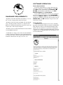
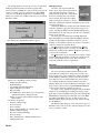
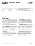
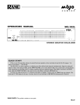
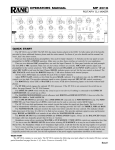
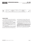
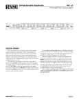
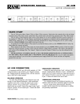
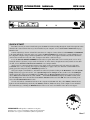
OPERATORS MANUAL
RPE 228
REMOTE PROGRAMMABLE EQUALIZER
QUICK START
Read this section if you want to install and operate the RPE 228 without wading through the detailed descriptions in this
manual. If the control software has not yet been installed on your computer, refer to SOFTWARE OPERATION on page
Manual-5 first.
Turn the amplifier(s) down or off until all connections are complete. Connect balanced audio INPUTS and OUTPUTS
to the handy Euroblock connectors on the rear. Connect the RW 232 INPUT jack on the rear to a serial (COM) port on a
PC-compatible computer using a standard 9-pin RS-232 cable (a short one is supplied with the unit, which is intended to
connect between units in a rack). The cable or adaptor must not be a null-modem type.
Locate the RW 232 DEVICE ADDRESS switch on the rear panel. If this unit is to be tested by itself, set it to ‘1’ by
setting all switches off (down), except switch one (labeled ‘1’ on the chassis, the right-most switch). If there is more than
one unit, refer to SETTING THE DEVICE ADDRESS to set a unique number.
Apply power by connecting the RS 1 remote power supply to the red telephone-style jack on the rear of the unit.
CAUTION: don’t connect anything but an approved RANE power supply to this jack. If the RS 1 and the RPE 228 are
getting power, the front panel yellow POWER light will be on.
Start your computer, run Windows®, and launch our software by double-clicking on the RaneWare® icon. The System
Setup window may appear. If it doesn’t, select System Setup from the Setup menu. Be careful to select the COM port
which is physically connected to the RPE 228. Click OK. Now, the Device Selection window may appear. If it doesn’t,
choose Select from the Device menu. Click on Poll, … and the Devices Found will display the number of units found.
Click the Stop button. Select the unit listed in the Device Selection window and click OK. If no unit was found, please
refer to the TROUBLESHOOTING section.
Several clues indicate communication between the computer and the RPE 228. The yellow COM (communications)
lights on the unit should flash periodically. The Memory numbers (1-16) near the top of the computer screen should be
black rather than grey. Clicking the BYPASS button on the screen causes one Channel of the unit to enter bypass.
WEAR PARTS: This product contains no wear parts.
Windows is a registered trademark of Microsoft Corporation.
RaneWare is a registered trademark of Rane Corporation
Manual-1
FRONT PANEL DESCRIPTION
햲 POWER indicates that the unit is happily connected to a powered remote supply.
햳 Parameter Switch adjusts the frequency of the Low-Cut filters for each Channel incrementally up to the maximum setting,
then down to the minimum setting, and back.
햴 COM (yellow, communications) flashes when a message for the unit or the specific Channel is received from a PC compatible computer. There is a brief flash when using the Remote Switch Interface is used.
햵 BYPASS (red) lights whenever the audio relay Bypass for the Channel is active. This occurs for a few seconds after powerup, or when BYPASS is selected in RaneWare.
햶 SIGNAL (green) indicates the presence of a significant audio signal on the Input to the Channel (typically -27 dBu).
햷 CLIP (red) flashes when an audio level for the Channel in the unit approaches the clipping level (typically 3 dB below
clipping).
RPE 228 CONNECTION
When connecting the RPE 228 to other components in
your system for the first time, leave the power supply for last.
This will give you a chance to correct any mistakes before
any damage is done to your speakers, ears, etc.
The RPE 228 will operate at moderately high ambient
temperatures. Large racks of equipment may generate excess
heat, requiring extra space beween units, and/or forced air
ventilation to reduce the ambient temperature in the rack.
The RPE 228 has balanced Inputs and Outputs, with
chassis-grounded shields. This chassis ground is not signal
ground, although the two grounds are connected internally.
The chassis ground is intended to be connected to an earth
ground. The RPE 228 is intended to be connected to other
balanced equipment with chassis-grounded shields. Connect
the non-inverting audio lines to the ‘+’ terminals, and the
inverting lines to the ‘–’ terminals. Connect the cable shields
to the center terminal on the terminal block. Connect shields
at both ends of the cables.
There is a #6-32 screw provided for chassis ground.
Connect a wire from this point to a known earth ground, such
as an amplifier chassis. This may not be necessary when
installed in a rack with other grounded units.
The RPE 228 requires a Rane RS 1 or compatible power
supply, provided with each unit. Optionally, our model RAP
Manual-2
10 power supply provides power for up to ten units at a time.
To control the units from a computer, use nine-pin RS-232
cables which are 50 feet or shorter. The cable must not be a
null-modem type. A short cable is supplied for connecting
adjacent units. Daisy-chain up to 16 units at a time by
connecting the COM port on the computer to the INPUT
connector on the first unit, and the OUTPUT connector of
each unit to the next unit’s INPUT.
The DEVICE ADDRESS switch identifies each unit with
an ‘address’, and must be set uniquely for each unit. The
switches form a binary code from 0 through 255. Only the
numbers 1-250 may be used. The place values of each switch
are marked on the rear panel. To set a specific address, refer
to the “Setting the Device Address” section.
The REMOTE SWITCH interface provides contact closure
control for up to eight preset memories. No computer is required
after the initial setup. There are nine screw terminals; one is
chassis ground, and the other eight are for Memories 1-8.
Connection of one of these to ground causes both Channels of
the unit to recall a preset Memory. Multiple units may be
controlled by connecting these terminals in parallel. Either
momentary or latching switches may be used. A latching switch
should only close one contact at a time. Use of a latching switch
results in an additional Memory recall upon power-up.
REAR PANEL DESCRIPTION
햲 Channel 2 Audio Input and Output are balanced. The center terminal is chassis ground.
햳 Channel 1 Audio Input and Output are balanced. The center terminal is chassis ground.
햴 DEFAULT switch recalls Memory 1 for both audio Channels. This may be useful in case of computer failure and duplicates the function of the number ‘1’ Remote Memory Switch—without the need for an external switch.
햵 REMOTE SWITCH provides the ability to recall one of 8 Memories using contact closures.
햶 RW 232 OUTPUT connects to the RW 232 INPUT on other units.
햷 RW 232 INPUT connects to the computer, or to the RW 232 OUTPUT of other RW 232 units.
햸 RW 232 DEVICE ADDRESS identifies each unit uniquely by assigning it a number from 1 to 250. Refer to the Device
Address Table on the following page.
햹 Chassis Ground Point is provided for chassis ground when required. Units with outboard power supplies do NOT ground
the chassis through the line cord. Make sure that these units are grounded either to another chassis which is earth grounded,
or directly to the grounding screw on an AC outlet cover by means of a wire connected to a screw on the chassis with a star
washer to guarantee proper contact. See TROUBLESHOOTING, back page.
햺 Remote POWER jack is for connection to a Rane RS 1 or compatible power supply.
CANADIAN EMC NOTICE
FCC NOTICE
This Class A digital apparatus meets all requirements of the Canadian Interference-Causing Equipment
Regulations.
Cet Appariel numerique de la classe A respecte
toutes les exigences du Reglement sur le material broilleur
du Canada.
This equipment has been tested and found to comply
with the limits for a Class A digital device, pursuant to
Part 15 of the FCC Rules. These limits are designed to
provide reasonable protection against harmful interference
when the equipment is operated in a commercial environment. This equipment generates, uses, and can radiate
radio frequency energy, and if not installed and used in
accordance with the instruction manual, may cause
harmful interference to radio communications. Operation
of the equipment in a residential area is likely to cause
harmful interference in which case the user will be
required to correct the interference at their own expense.
Changes or modifications not expressly approved by Rane
Corporation could void the user's authority to operate the
equipment.
Manual-3
SETTING THE DEVICE ADDRESS
The Device Address is set using a binary code which may be determined using the following table,
our Windows Address Calculator program, or by adding the place values (1-128) silkscreened on the
chassis. Ignore any numbers printed directly on the switch. For example, turning ON the switches labeled
‘1’ and ‘2’ yields address ‘3’. In the following table, 0 means switch down (OFF), 1 means switch up
(ON), and the left-most digit corresponds to the switch labeled ‘128’. Rane provides a special calculator
to assist in setting the dip switches on the back of each unit. Alt-Tab to the Windows Program Manager,
and in the RaneWare program group, launch the RaneWare Address Calculator. This binary
calculator converts decimal numbers into corresponding dipswitch settings.
151 10010111
51 00110011
101 01100101
1 00000001
152 10011000
52
00110100
102
01100110
2 00000010
153 10011001
53
00110101
103
01100111
3 00000011
154 10011010
54
00110110
104
01101000
4 00000100
155 10011011
55
00110111
105
01101001
5 00000101
156 10011100
56
00111000
106
01101010
6 00000110
157 10011101
57
00111001
107
01101011
7 00000111
158 10011110
58
00111010
108
01101100
8 00001000
159 10011111
59
00111011
109
01101101
9 00001001
160 10100000
60
00111100
110
01101110
10 00001010
161 10100001
61
00111101
111
01101111
11 00001011
162 10100010
62
00111110
112
01110000
12 00001100
163 10100011
63
00111111
113
01110001
13 00001101
164 10100100
64
01000000
114
01110010
14 00001110
165 10100101
65
01000001
115
01110011
15 00001111
166 10100110
66
01000010
116
01110100
16 00010000
167 10100111
67
01000011
117
01110101
17 00010001
168 10101000
68
01000100
118
01110110
18 00010010
169 10101001
69
01000101
119
01110111
19 00010011
170 10101010
70
01000110
120
01111000
20 00010100
171 10101011
71
01000111
121
01111001
21 00010101
172 10101100
72
01001000
122
01111010
22 00010110
173 10101101
73
01001001
123
01111011
23 00010111
174 10101110
74
01001010
124
01111100
24 00011000
175 10101111
75
01001011
125
01111101
25 00011001
176 10110000
76
01001100
126
01111110
26 00011010
177 10110001
77
01001101
127
01111111
27 00011011
178 10110010
78
01001110
128
10000000
28 00011100
179 10110011
79
01001111
129
10000001
29 00011101
180 10110100
80
01010000
130
10000010
30 00011110
181 10110101
81
01010001
131
10000011
31 00011111
182 10110110
82
01010010
132
10000100
32 00100000
183 10110111
83
01010011
133
10000101
33 00100001
184 10111000
84
01010100
134
10000110
34 00100010
185 10111001
85
01010101
135
10000111
35 00100011
186 10111010
86
01010110
136
10001000
36 00100100
187 10111011
87
01010111
137
10001001
37 00100101
188 10111100
88
01011000
138
10001010
38 00100110
189 10111101
89
01011001
139
10001011
39 00100111
190 10111110
90
01011010
140
10001100
40 00101000
191 10111111
91
01011011
141
10001101
41 00101001
192 11000000
92
01011100
142
10001110
42 00101010
193 11000001
93
01011101
143
10001111
43 00101011
194 11000010
94
01011110
144
10010000
44 00101100
195 11000011
95
01011111
145
10010001
45 00101101
196 11000100
96
01100000
146
10010010
46 00101110
197 11000101
97
01100001
147
10010011
47 00101111
198 11000110
98
01100010
148
10010100
48 00110000
199 11000111
99
01100011
149
10010101
49 00110001
200 11001000
100
01100100
150
10010110
50 00110010
Manual-4
201
202
203
204
205
206
207
208
209
210
211
212
213
214
215
216
217
218
219
220
221
222
223
224
225
226
227
228
229
230
231
232
233
234
235
236
237
238
239
240
241
242
243
244
245
246
247
248
249
250
11001001
11001010
11001011
11001100
11001101
11001110
11001111
11010000
11010001
11010010
11010011
11010100
11010101
11010110
11010111
11011000
11011001
11011010
11011011
11011100
11011101
11011110
11011111
11100000
11100001
11100010
11100011
11100100
11100101
11100110
11100111
11101000
11101001
11101010
11101011
11101100
11101101
11101110
11101111
11110000
11110001
11110010
11110011
11110100
11110101
11110110
11110111
11111000
11111001
11111010
SOFTWARE OPERATION
RANEWARE REQUIREMENTS
• RaneWare 232 works under Microsoft Windows 3.1, 95 or
NT® on a PC or laptop with an unused serial port.
• RaneWare 232 needs a fully wired DB9 cable less than 50'
long, connecting from the serial port of a computer to the
RPE 228 communications input port. No interface boxes are
required; just a cable and your computer.
• RaneWare 232 can be fully demonstrated and used without
an actual RPE 228 attached.
Step by Step Installation
If you have the RaneWare 3.5" floppy disk, insert it in
your drive. In Windows 3.1 Program Manager, under File,
select Run. On the command line, type A:\install. Click
OK. This starts installation. In Windows 95, use Add/
Remove Programs in the Control Panel.
If you downloaded RaneWare from the web, decompress
the file first. Create a new directory named RANEWARE,
and move the RW232***.EXE file to this new directory. Now
run this file, and all the separate files will decompress. Locate
INSTALL.EXE, click OK. Installation now proceeds as file
locations are verified.
Starting RaneWare
A RaneWare program group is now created, containing
RaneWare, the RaneWare Address Calculator, and RaneWare
Help. When the software is first installed, RaneWare Help
appears. Here any questions can get answered. Subsequent
activation does not bring up RaneWare Help until you ask for
it. But let’s get on with the program. Close the Help file, and
welcome to RaneWare!
• A RaneWare 3½" floppy comes with each unit. Installation
is simple and follows standard procedure with both Windows
3.1 and 95. The latest version is downloadable 24 hours a day
from Rane’s Internet web site, http://www.rane.com.
Manual-5
The startup splash screen stays up for a few seconds, then
Polling begins the first time you run the program. This
process checks if any RPEs are connected to the serial port. If
a Device is found, you are in control! (If not, with an RPE
connected, read the Help file [Reference, Troubleshooting
Hints]). If you don’t have an RPE connected, you can still use
RaneWare offline.
After Polling, the Graph Editing window appears.
Changing curves
Go ahead, grab any slider with the
mouse cursor. An accurate representation
of the full audio frequency response is
portrayed in the graph. Once a filter band
is selected, clicking above or below the
slider can make fine half decibel adjustments. The up/down cursor keys can also
make these adjustments, while the left/right keys move from
one band to the next.
Clicking the Select key changes the audio Channel being
controlled. Channel 1 appears in red. Channel 2 appears in
yellow. Checking the Both box under Graph Display shows
both Channels at the same time, but only the active Channel’s
sliders can be operated.
Go ahead, play! You'll find Low and High Cut filters,
Input and Output level controls, Mute and Bypass switches,
just like our other high end equalizers. Only now you can
instantly see the equalizer response! If you have an equalizer
connected, changes are instantly heard.
The Device menu contains a few handy tools. Flatten
does just that, and gives you a clean slate on either or both
Channels by clicking in the submenu. Copy lets you transfer
a curves between Channels.
The Views menu lets you switch between viewing a single
channel with graph and sliders, or both sets of sliders on one
screen, or both graphs on one screen. This is useful for
comparing channels and stereo equalization.
Memories
When active, the Editing window provides:
• Memory Recall & Storing
• EQ Band Editing
• Low & High Cut Filter Adjustment
• Input & Output Level Control
• Bypass & Mute
• Local Edit Mode, which allows you to alter the EQ
without immediately changing the unit
• Display of current control settings using the right
mouse button
The menus also provide:
• Extensive On-Line Help
• Device Selection
• Device Naming
• Device Settings Backup (to computer disk)
• Memory Channel Copying
• EQ Curve and Report Printing
• Device Locking
• Three different Device Editing Channel Views
• Changing Password
Manual-6
The red local memory number flashes to indicate that
current Memory settings have changed. If you wish to save
these settings in one of the 16 Memories, simply click Store,
and the Memory number key. It's that easy! Go ahead and
store different curves in different Memories. After storing a
few, clicking any Memory number instantly recalls that
Memory. Store your favorites in Memories 1 through 8, since
these can be recalled via the rear panel REMOTE SWITCH
contact closures when the computer is removed.
To change a curve without affecting the audio in the RPE,
simply select Local Edit before making any changes, make
them, and re-click Local Edit. You will be asked: Accept the
Edited Curve? Answering Yes sends that curve to the RPE
228. While Local Edit is selected, clicking on any of the
Memory buttons displays the preview curve without sending
it to the RPE 228.
The Device button brings up a selection menu of up to 15
RaneWare units connected to the computer. Simply select the
device you wish to control.
Device > Name Device
System > Edit Installation Info
Devices and channels can also be given custom names,
tailored to your installation.
If your installation changes by adding more RaneWare
units, choose Device > Select, and the POLL button to
make the computer recognize currently connected units in the
system.
When multiple units are connected, assign each unit a
unique Device Address number. See page Manual-4.
This selection allows you to enter the Project name,
installation Site and System Engineer for a given project. All
of these are printed on the Device Report printouts. Click in
the edit box or hold the Alt key and press the underlined
character to type new names.
Similar to the password, the Site Installation Info is stored
in the computer, not in each unit. The Site Installation Info is
also stored with backup Memories when you save a unit’s
Memories to a file.
Security
The RPE can be operated on a daily basis either through a
computer or through the contact closures. To preserve preset
security with a computer operator, the software can be locked
(under Device), and a system password can be assigned
(under System > Change Password). The default password
is please.
System > Site Control Panel Setup
Presets can be customized with names, through System >
Site Control Panel Setup. Here each Memory can have a
logical name.
With the device locked, and a user tries to change a curve,
this friendly screen appears.
System > Site Control Panel
Manual-7
This Site Control Panel is all an operator needs to see to
recall memories. If only a few presets are required, blanking
an entry in the Site Control Panel Setup removes the button
from this screen, reducting the number of buttons. A password is not required to operate the RPE from this screen.
If more than 16 memories are needed, they can be saved
to disk and recalled later. For mobile sound trucks, presets for
a particular venue can be saved to disk and loaded when
returning to that venue. Memory names are stored in the
computer, along with other site information. Job files can be
used for multiple installations. Printouts of device data,
graphs, and curves are available for those who still like to file
paper. These can be kept in the project file.
Hints for Windows 95 Users
If you find yourself squeezed for room at the bottom of
the screen, you can modify the Task Bar so it only appears
when you move the mouse pointer below the bottom of the
screen.
To do this,
Right-Click on a blank spot on the task bar.
Select Properties
Enable Auto Hide
Press OK.
While operating the Device Control Panel in Windows 95,
there is no button-box for the system menu on the title bar.
There is, however, a Close-Window button-box.
As expected, the Close-Window button-box does exit the
Device Control Panel, but unfortunately, it also quits
RW 232.
To get back to edit mode, Right-Click the mouse on the
Device Control Panel title bar. This will open the menu
allowing you to return to Device Edit mode or exit the
program altogether. As usual, a password is required for
either option.
TROUBLESHOOTING
POWER LED is Off:
Check POWER connection on rear panel, and that the remote
supply is connected to a live AC source.
No communication between the unit and the computer:
Set the DEVICE ADDRESS to a unique small number,
and try polling for units in RaneWare (under Device >
Select, Poll). The unit should be found quickly. If more than
16 units are daisy-chained from one serial port, communication to the furthest units may be unreliable.
Check that the COM port selected in RaneWare (under
Setup > System Setup) is the one on your computer that is
connected to the unit.
Check that the cable is a standard RS-232 cable (not a null
modem type). If an adaptor is used, it must not be null
modem. The cable must be connected to the RW 232 INPUT
jack on the rear of the unit.
Audio hum or noise:
Try Muting the unit. If this helps significantly, the
problem may be with the Input connection, or the equipment
driving the Input. If Muting has little effect, the problem is
likely either the Output connection, or equipment driven by
the Output.
The RPE 228 is intended to connect with equipment with
balanced audio I/O and chassis-grounded shield/common.
This kind of audio interconnection should maximize audio
quality. Connecting equipment with signal grounded shields
or unbalanced connections may result in hum or noise due to
induced currents in the signal path. It may be possible to
reduce or eliminate these problems, although some experimentation may be required:
Try disconnecting the audio cable shields at one end,
particularly between chassis grounded and signal grounded
equipment.
Try combinations of lifting grounds on units supplied with
ground lift switches (or links).
Verify that all chassis are tied to a good earth ground.
Units with outboard power supplies do not ground the
chassis through the line cord. Make sure these units are
grounded by tying the Chassis Ground Point to a known earth
ground. A star washer guarantees proper contact.
For more information on balanced interconnection and
grounding, please refer to RaneNote 110, “Sound System
Interconnection”(next section).
©Rane Corporation 10802 47th Ave. W., Mukilteo WA 98275-5098 TEL (425)355-6000 FAX (425)347-7757 WEB http://www.rane.com
Manual-8
All features & specifications subject to change without notice.