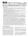
1
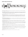
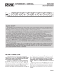
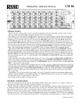
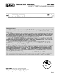
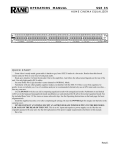
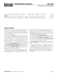
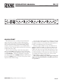
OPERATORS MANUAL
PE 17
PARAMETRIC EQUALIZER
GAIN
CUT FILTERS
+12
–12
OL
0
0
BYPASS
–12
+12
IN
OUT
250
180
80
35
20
10
LOW
3k
5k
LEVEL
-3
-6
10k
-12
-15
30k
40k
HIGH
1
BANDWIDTH
FREQUENCY
235 460
3
6 150
1k
9
12
100 2k
dB
Hz
x10 x1 x0.1
FREQ
0.6
LEVEL
2
BYPASS
BANDWIDTH
FREQUENCY
1.0
-3
235 460
3
1.8 -6
6 150
1k
-12
9
.03
2.0
-15
12
100 2k
OCTAVE
dB
Hz
0.3
x10 x1 x0.1
FREQ
0.6
LEVEL
3
BANDWIDTH
FREQUENCY
1.0
-3
235 460
3
1.8 -6
6 150
1k
-12
9
.03
2.0
-15
12
100 2k
OCTAVE
dB
Hz
0.3
BYPASS
x10 x1 x0.1
FREQ
0.6
LEVEL
4
BYPASS
BANDWIDTH
FREQUENCY
1.0
-3
235 460
3
1.8 -6
6 150
1k
-12
9
.03
2.0
-15
12
100 2k
OCTAVE
dB
Hz
0.3
x10 x1 x0.1
FREQ
0.6
0.3
BYPASS
1.0
1.8 -6
.03
2.0
OCTAVE
LEVEL
5
BANDWIDTH
FREQUENCY
-3
235 460
3
6 150
1k
9
-15
12
100 2k
dB
Hz
x10 x1 x0.1
FREQ
0.6
0.3
BYPASS
1.0
1.8
.03
2.0
OCT.
PE 17
PARAMETRIC
EQUALIZER
POWER
QUICK START
Those who choose not to read this modest informational
snippet (intended to ward off one of life’s embarrassing moments) are those who wish to hasten the point at which their
entire sound system locks up, screams unmercifully, shatters
windows, causes dogs to howl, babies to cry, and melts all the
compression drivers, dripping molten titanium all over the handpolished walnut decor. Pity.
There are only a few things to check when using a PE 17.
Always set both GAIN controls as close to the top of the panel
as possible without causing the OL LED to light constantly. Use
the CUT FILTERS to tailor the bandwidth for each application. Always check that each FREQ X multiplier switch (located
beneath each FREQ control) is set to the correct position. Great
surprises result from false settings.
WEAR PARTS: This product contains no wear parts.
For extra-deep notching applications, use Bands 3 and 4 and
set them exactly the same. Notches as deep as 30 dB are possible,
since Bands 3 and 4 are in series while most other bands are in
parallel (see the Block Diagram in the Data Sheet).
Hook-up is simple. The PE 17 accepts all combinations of
balanced or unbalanced, XLR or ¼" connectors. However, the
INPUT connectors are wired in parallel and may not be used
together. Use only one at a time. They will not function as a summing type of input for two different sources, but they may be used
in a daisy chain fashion to feed other units. On the other hand
(to randomly pick a hackneyed expression), you may use the
paralleled Outputs to drive two destinations.
Never connect anything except a Rane approved AC power
supply to the thing that looks like a red telephone jack on the
rear of the PE 17.
Manual-
FRONT PANEL DESCRIPTION
1
5
GAIN
CUT FILTERS
+12
–12
OL
0
0
BYPASS
–12
+12
IN
OUT
2 3
250
180
80
35
20
10
3k
5k
LEVEL
-3
-6
10k
-12
-15
30k
40k
LOW
HIGH
4
7
1
8
BANDWIDTH
FREQUENCY
235 460
3
6 150
1k
9
12
100 2k
dB
Hz
x10 x1 x0.1
FREQ
6
0.6
LEVEL
2
-3
235 460
3
1.8 -6
6 150
1k
-12
9
.03
2.0
-15
12
100 2k
OCTAVE
dB
Hz
BYPASS
BANDWIDTH
FREQUENCY
1.0
0.3
x10 x1 x0.1
FREQ
0.6
LEVEL
3
BYPASS
BANDWIDTH
FREQUENCY
1.0
-3
235 460
3
1.8 -6
6 150
1k
-12
9
.03
2.0
-15
12
100 2k
OCTAVE
dB
Hz
0.3
x10 x1 x0.1
FREQ
0.6
LEVEL
4
BYPASS
BANDWIDTH
FREQUENCY
1.0
-3
235 460
3
1.8 -6
6 150
1k
-12
9
.03
2.0
-15
12
100 2k
OCTAVE
dB
Hz
0.3
x10 x1 x0.1
FREQ
0.6
0.3
BYPASS
9
1.0
1.8 -6
.03
2.0
OCTAVE
LEVEL
5
BANDWIDTH
FREQUENCY
-3
235 460
3
6 150
1k
9
-15
12
100 2k
dB
Hz
x10 x1 x0.1
FREQ
0.6
0.3
BYPASS
1.0
1.8
.03
2.0
OCT.
PE 17
PARAMETRIC
EQUALIZER
POWER
10
1 Overall OverLoad indicator: illuminates whenever the signal level at any of five critical nodes comes within 3 dB of clipping.
2 Overall BYPASS switch & indicator: Engaging this pushbutton energizes the Bypass relay. This provides a complete hard-wire
Bypass of the PE 17 with no active electronics in the signal path. A red LED indicates the unit is in the BYPASS mode. In the out
(LED off ) position, the Input is routed through the active electronics. The Bypass relay is wired such that upon power failure it
reverts to the BYPASS condition, thus providing a “fail-safe” feature.
3 IN & OUT GAIN controls: set the relative IN and OUT gain structures. The range of each is ±12 dB; however, note that the
labeling is opposite to each other, e.g., the top of the IN control reads +12 dB while the top of the OUT control reads -12 dB.
Configured this way, whenever they are held and moved together the overall gain through the PE 17 stays at unity. Positioning
these controls (together) as far toward the top of the panel as possible (without lighting the OL indicator) yields the best signal-to-noise
performance.
4 LOW & HIGH CUT FILTER controls: set the corner frequencies of the band limiting filters. The frequencies shown represent
the -3 dB points for each filter. When the sliders are located at their bottom-most positions, the filters are at their lowest and highest extremes and thus, effectively bypassed.
5 FILTER LEVEL control: The center detent position guarantees flat response through the respective filter due to its grounded
center-tap design. Full clockwise rotation yields 12 dB of boost, while full counterclockwise rotation gives you 15 dB of cut.
6 FREQUENCY multiplier switch: The markings on this three position slide switch indicate the factor by which the calibrations
of the Frequency sweep control (7) are multiplied. For instance, if the range switch is in the “x0.1” position and the FREQUENCY control is at “460,” then the actual center frequency of the filter is 46 Hz. Operation of this switch in conjunction with the
FREQUENCY control yields a range of 10 Hz to 20 kHz for each band.
7 FREQUENCY sweep control: increases the center frequency of the filter band as it is turned clockwise. It is calibrated from
“100” to “2k.” The exact frequency is determined by multiplying the value indicated by the frequency multiplier switch (6).
8 Individual band BYPASS switch & indicator: Each of the five filter BYPASS switches disables the respective filter, providing instant comparison between flat response and equalized response. The red LED illuminates when the band is in the BYPASS mode.
9 BANDWIDTH control (Q): Full counterclockwise rotation yields a Bandwidth of 1/30-octave (Q=43) in the respective filter,
while full clockwise rotation gives a 2 octaves (Q=0.67) bandwidth.
0 POWER indicator: When this yellow LED is lit, the unit is powered and ready to command.
Manual-
REAR PANEL DESCRIPTION
PE 17
POWER
MADE IN U.S.A.
RANE CORP.
WIRING
TIP / PIN 2 = POSITIVE
RING / PIN 3 = NEGATIVE
SLEEVE = SIGNAL GROUND
PIN 1 = CHASSIS GROUND
TRS
PATCH I/O
TRS
PATCH I/O
MAY CONNECT TO THE INSERT
LOOP OF OTHER EQUIPMENT
USING A 1/4" TRS CABLE.
CAUTION! DO NOT USE THE
PATCH I/O WITH ANOTHER
INPUT! SEE THE MANUAL!
WIRING
450mA
CLASS 2 EQUIPMENT
4
ACN 001 345 482
OUTPUTS
MAY USE BOTH
5
2
TIP = INPUT
RING = OUTPUT
SLEEVE = CHASSIS GROUND
3
INPUTS
USE ONLY ONE
1
1 XLR & ¼" TRS INPUT jacks: Choose between one of these inputs. The ¼" TRS Input is a differentially active balanced, auto
unbalanced ¼" INPUT connector; tip = positive, ring = negative, and sleeve = signal ground. For unbalanced operation, use only a
standard mono (single conductor )tip-sleeve (no ring) plug. The balanced XLR INPUT connector is wired: pin 1 chassis ground, pin
2 positive, and pin 3 negative. These Inputs parallel each other and may be used for daisy chaining purposes, but do not use to sum
two Inputs together.
2 XLR & ¼" OUTPUT jacks: These jacks are active balanced Ouputs. The ¼" TRS tip is signal positive, the ring is signal negative
and the sleeve is signal ground. The 3-pin wiring is per IEC/ANSI/AES standards: pin 1 signal ground, pin 2 positive, and pin 3
negative. These jacks parallel each other and unlike the Input, may deliver two Ouputs simultaneously.
3 PATCH I/O connector: This ¼" TRS jack provides an unbalanced I (Input) on its tip and an unbalanced O (Output) on its
ring. This is designed for use with tip=send/ring=return effect loops found on many mixing consoles, providing an easy means for
patching the unit into effect loops using only a single ¼" TRS (2-conductor) patch cable. Caution: Use either the PATCH I/O or
the INPUT and OUTPUT connectors — do not use both. These are not summing Inputs.
4 Remote POWER supply input: This unit is supplied from the factory with a model RS 1 Remote AC Power Supply suitable for
connection to this jack. This unit requires an 18 volt AC center-tapped transformer only. This is not a telephone jack. Never use a
power supply other than the one supplied or a Rane approved replacement.
5 Chassis ground point: A #6-32 screw used for chassis grounding purposes. See the note below.
CHASSIS GROUNDING
After hooking up your system, if it exhibits excessive hum or buzzing, an incompatibility in the grounding configuration between
units exits. Ha! Now you earn your money, now you pay the piper. Now you must discover how your particular system wants to be
grounded! Here are some things to try:
Always use balanced interconnection methods—but, when you can’t:
1. Try combinations of lifting grounds on units supplied with ground-lift switches or jumpers.
2. If your equipment is in a rack, verify that all chassis are tied to a good earth ground, either through the line cord grounding pin or
the rack screws to another grounded chassis.
Units with outboard power supplies like the PE 17, do not ground the chassis through the line cord. Make sure this unit is grounded
either to another chassis which is earth grounded (like the power amplifier), or directly to the grounding screw on an AC outlet cover
by means of a wire connected to the chassis ground point found on the rear to guarantee proper contact.
See the included RaneNote “Sound System Interconnection” for more troubleshooting and specific cable matching.
Manual-
PE 17 CONNECTION
The PE 17 is compatible with all line-level (-10 dBV and +4
dBu) interfaces and products. However, you must amplify microphones and other mic-level products before connecting them to
the PE 17.
The proper connection of this unit to a system is a relatively
simple matter, the specifics of which may vary greatly depending
on the application. Use a PE 17 anywhere line-level frequency
contouring is required. This includes live sound reinforcement
systems, recording studios, dance clubs, etc.
For live or recorded sound systems the most common location to insert a parametric equalizer is immediately preceding the
active crossover or power amplifier. This provides the means to
correct loudspeaker deficiencies required in any system for high
quality reproduction. Many systems employ both a graphic and
parametric equalizer connected in series. The graphic finds use in
personal preference or program equalization, while the parametric helps with sources, loudspeaker compensation and feedback
control. In these situations, the order of placement is not critical,
however the PE 17 does feature servo cross-coupled balanced
Outputs which allows use in installations requiring very long
cable runs between the equalizers and the power amplifiers or
crossovers.
The ¼" TRS and XLR Input connectors are wired in parallel
and are actively balanced. These Inputs are provided primarily to
give the user a choice between two types of connectors. They will
not function as a summing type of input for two different sources.
For further information on this subject, please consult the RaneNote, “Why Not Wye?,” available from the Rane website. The
two Inputs may be used in a daisy chain application where the
Input to the PE 17 also must feed another piece of equipment.
The Outputs of the PE 17 offer the same connector choice.
They also are wired in parallel and are actively balanced. However, both Outputs may be used simultaneously if desired.
All XLR connectors used by Rane are wired per the IEC/
ANSI/AES standard as follows: pin 2 positive, pin 3 negative
and pin 1 chassis ground. Unbalanced use of a PE 17 is not recommended. See the “Sound System Interconnection” RaneNote
included with this manual.
OPERATING INSTRUCTIONS
Now it is knob twisting time! Power up the system in the
normal fashion, always turning on the power amplifiers last. It is
good practice to start at the head of the system, turning on any
sound sources and mixers first, equalization devices next, and
finally power amplifiers. Following this power-up sequence minimizes the change of high gain stage turn-on transients finding
their way to the loudspeakers.
GAIN
CUT FILTERS
+12
–12
OL
0
0
BYPASS
–12
+12
IN
OUT
250
180
80
35
20
10
LOW
3k
LEVEL
1
FREQUENCY
BANDWIDTH
-3
Going from left-to-right along the front panel, make the following initial settings:
Slide both GAIN controls all the way to the top.
Slide both FILTER controls all the way to the bottom.
Set the five LEVEL controls to their center detents.
Disengage all (6) BYPASS pushbuttons (out, LEDs off).
Check that the POWER LED is lit.
With either a canned or live source applied, observe the OL
(OverLoad) light (located at the extreme left-hand side of the
front panel) for a few moments to see if it lights occasionally, or
all the time. If the OL light stays lit most of the time, then slide
both sliders (grasp together) down just enough for the lights to
only light every so often. This is the proper setting for the best
signal-to-noise performance. Now you are ready to make some
adjustments.
PE 17s often find themselves in recording studios, but some
get used for room equalization. Details lie outside the scope of
this manual; however, a few words can’t hurt.
Experienced sound people almost always use some sort of
analyzer as an aid in setting equalization. Professional system
analysis tools are available that can discriminate between room
acoustics and system response. SIA Software Company, Inc.,
have developed tools, including SmaartLive and SIA Acoustic
Tools, that allow sound system measurement and acoustic analysis. The software is designed for serious pro audio and acoustical
consultant engineers. For more information visit www.siasoft.
com. Once the system is tuned, lock the PE 17 behind a security
cover (available separately).
As a notch filter, the PE 17 works very well in increasing system headroom by attenuating system peaks that create feedback
problems. The obvious goal in notching is to remove only the
problem areas and nothing else. With this in mind, it is always
a good idea to first try to notch out feedback with the BANDWIDTH controls set to their full counterclockwise positions.
The acoustic resonance points causing feedback are generally so
narrow that a filter bandwidth set at .03 octave easily cures the
problem. To chase down the feedback frequency, start with the
filter LEVEL control set to its full -15 dB position. With the BW
still set to minimum, tune the FREQ control until the feedback goes away. It shouldn’t take too much fine tuning to find
the center of the resonance. Once you have achieved stability,
advance the system level until feedback starts to reappear, then
back it down slightly. If a -15 dB cut won’t cure the problem, the
resonance is extreme and must be dealt with in other ways. For
example, move the speakers or the mics; hang some drapes; move
some walls; burn down the building—no, chill out. Rane makes
some other great parametrics such as the PEQ 55 and in the
RPM series that may solve some of your other system issues.
©Rane Corporation 10802 47th Ave. W., Mukilteo WA 98275-5098 USA TEL 425-355-6000 FAX 425-347-7757 WEB www.rane.com
Manual-
LEVEL
235 460
0.6 1.0
-3
3
-6
6 150
1k
0.3
1.8 -6
10k
-12
9
-12
-15
12
100 2k
.03
2.0
-15
12
30k
dB
Hz
OCTAVE
dB
40k
BYPASS
x10 x1 x0.1
x1
HIGH
FREQ
5k
103051