1
pITX-E38
KTD-N0904-E
The pulse of innovation
Error! Use the Home tab to apply Überschrift 1 to the text that you want to appear here.
Table of Contents
» Table of Contents «
1
Introduction ........................................................................................... 5
2
Installation Procedure .............................................................................. 6
2.1
Installing the Board ................................................................................................................ 6
2.2
Requirements IEC60950 ........................................................................................................... 7
3
System Specifications ............................................................................... 8
3.1
Component main data .............................................................................................................. 8
3.1
System overview .................................................................................................................... 11
3.2
Integrated premounted cooler .................................................................................................. 11
3.1
System Memory Support .......................................................................................................... 12
3.2
Power Consumption................................................................................................................ 13
4
Connector Locations ............................................................................... 14
4.1
pITX-E38 - frontside ............................................................................................................... 14
4.2
pITX-E38 - backside ................................................................................................................ 15
5
Connector Definitions ............................................................................. 16
6
IO-Area Connectors ................................................................................ 17
6.1
DP Connectors (DP1) .............................................................................................................. 17
6.2
Ethernet Connector ................................................................................................................ 18
6.1
USB Connectors (IO Area) ........................................................................................................ 19
6.2
DC Power Jack Connector (5Vin Ext.) .......................................................................................... 21
7
Internal Connectors ................................................................................ 22
7.1
Internal Power Connector (Vin Int.) ........................................................................................... 22
7.2
Fan Connector (Fan) ............................................................................................................... 22
7.1
LVDS Flat Panel Connector (LVDS).............................................................................................. 23
7.2
SATA (Serial ATA) Disk interface (SATA0) ..................................................................................... 24
7.3
USB Connectors (USB2 and USB3) ............................................................................................. 25
7.4
Serial COM1 – COM2 Ports (COM1, COM2) ..................................................................................... 26
7.5
Audio Connector .................................................................................................................... 27
7.6
Front Panel Connector (FRONTPNL) ............................................................................................ 27
7.7
Battery Module...................................................................................................................... 28
GPIO Connector (GPIO) .............................................................................................................................. 28
SBC Connector (SBC-Connector) .................................................................................................................. 28
7.8
SBC-GPIO Connector (SBC-GPIO) ............................................................................................... 29
7.9
SBC-External battery (SBC-Ext-Bat) ........................................................................................... 29
7.10
Clear CMOS (CLR-CMOS) ........................................................................................................... 29
7.11
“Always On” (Always On) ......................................................................................................... 30
7.12
SPI Connector (SPI) ................................................................................................................ 30
7.13
XDP (XDP) ............................................................................................................................ 31
pITX-E38 Users Guide
Error! Use the Home tab to apply Überschrift 1 to the text that you want to appear here.
Table of Contents
8
Slot Connectors (mPCIe, mSATA, MicroSD card) ............................................ 32
8.1
mPCIe or mSATA slot ............................................................................................................... 32
8.2
MicroSD card slot ................................................................................................................... 33
9
On-board - & mating connector types ......................................................... 34
10
BIOS .................................................................................................... 35
10.1
Main ................................................................................................................................... 35
System Information .................................................................................................................................. 36
Boot Features .......................................................................................................................................... 37
Boot Features .......................................................................................................................................... 39
10.2
Advanced ............................................................................................................................. 40
CPU Configuration .................................................................................................................................... 41
Uncore Configuration ................................................................................................................................ 43
LAN Configuration .................................................................................................................................... 45
Hardware Monitor ..................................................................................................................................... 46
Display Configuration ................................................................................................................................ 47
South Cluster Configuration........................................................................................................................ 48
Security Configuration ............................................................................................................................... 55
Thermal .................................................................................................................................................. 56
10.3
Security ............................................................................................................................... 57
10.4
Boot ................................................................................................................................... 58
10.5
Exit..................................................................................................................................... 59
pITX-E38 Users Guide
KTD-N0904-E
Page 2
Document Details
Document Revision History
Revision
Date
By
Comment
E
January 26th 2015
MLA
D
Nov. 6th 2014
MLA
C
Sept. 25th 2014
MLA
Battery Module Connector type added. TPM in BIOS section removed. Added
note for mSATA selection in BIOS. Added warning when changing cooling
system.
<F2> changed to <Del> - key to enter BIOS Menu. Added note on “OS
Selection”. SD changed to MicroSD. Added System Memory Support. Updated
BIOS part. Added reference to COM port setup Application Note.
Lithium battery info corrected.
rd
B
Sept. 23 2014
MLA
A
July 15th 2014
MLA
0
April 1st 2014
MLA
Added info to DC Power Jack connector. Environmental Conditions update.
Added note on mPCIe fixing tool.
Added Frontpanel Pin 1 indication. Reference to “Flex” removed. Power
Consumption Measurrements added. Added Cooler, Battery Module and
connector list. Added cable kits and BIOS part.
Preliminary version
Copyright Notice
Copyright 2013, KONTRON Technology A/S, ALL RIGHTS RESERVED.
No part of this document may be reproduced or transmitted in any form or by any means, electronically or
mechanically, for any purpose without the express written permission of KONTRON Technology A/S.
Trademark Acknowledgement
Brand and product names are trademarks or registered trademarks of their respective owners.
Disclaimer
KONTRON Technology A/S reserves the right to make changes without notice to any product, including
circuits and/or software described or contained in this manual in order to improve design and/or
performance.
Specifications listed in this manual are subject to change without notice. KONTRON Technology assumes no
responsibility or liability for the use of the described product(s), conveys no license or title under any
patent, copyright or mask work rights to these products and makes no representations or warranties that
these products are free from patent, copyright or mask work right infringement unless otherwise specified.
Applications that are described in this manual are for illustration purposes only. KONTRON Technology A/S
makes no representation or warranty that such application will be suitable for the specified use without
further testing or modification.
pITX-E38 Users Guide
KTD-N0904-E
Page 3
Document Details
Life Support Policy
KONTRON Technology’s PRODUCTS ARE NOT FOR USE AS CRITICAL COMPONENTS IN LIFE SUPPORT DEVICES OR
SYSTEMS WITHOUT EXPRESS WRITTEN APPROVAL OF THE GENERAL MANAGER OF KONTRON Technology A/S.
As used herein:
Life support devices or systems are devices or systems which (a) are intended for surgical implant into body
or (b) support or sustain life and whose failure to perform when properly used in accordance with
instructions for use provided in the labelling can be reasonably expected to result in significant injury to
the user.
A critical component is any component of a life support device or system whose failure to perform can be
reasonably expected to cause the failure of the life support device or system or to affect its safety or
effectiveness.
Warranty
KONTRON Technology warrants its products to be free from defects in material and workmanship during the
warranty period. If a product proves to be defective in material or workmanship during the warranty period
KONTRON Technology will, at its sole option, repair or replace the product with a similar product.
Replacement Product or parts may include remanufactured or refurbished parts or components.
The warranty does not cover:
1. Damage, deterioration or malfunction resulting from:
A. Accident, misuse, neglect, fire, water, lightning or other acts of nature, unauthorized
product modification or failure to follow instructions supplied with the product.
B. Repair or attempted repair by anyone not authorized by KONTRON Technology.
C. Causes external to the product, such as electric power fluctuations or failure.
D. Normal wear and tear.
E. Any other causes which does not relate to a product defect.
2. Removal, installation and set-up service charges.
Exclusion of damages:
KONTRON TECHNOLOGY LIABILITY IS LIMITED TO THE COST OF REPAIR OR REPLACEMENT OF THE PRODUCT.
KONTRON TECHNOLOGY SHALL NOT BE LIABLE FOR:
1. DAMAGE TO OTHER PROPERTY CAUSED BY ANY DEFECTS IN THE PRODUCT, DAMAGES BASED UPON
INCONVENIENCE, LOSS OF USE OF THE PRODUCT, LOSS OF TIME, LOSS OF PROFITS, LOSS OF
BUSINESS OPPORTUNITY, LOSS OF GOODWILL, INTERFERENCE WITH BUSINESS RELATIONSHIPS OR
OTHER COMMERCIAL LOSS, EVEN IF ADVISED OF THEIR POSSIBILITY OF SUCH DAMAGES.
2. ANY OTHER DAMAGES, WHETHER INCIDENTAL, CONSEQUENTIAL OR OTHERWISE.
3. ANY CLAIM AGAINST THE CUSTOMER BY ANY OTHER PARTY.
pITX-E38 Users Guide
KTD-N0904-E
Page 4
Document Details
KONTRON Technology Technical Support and Services
If you have questions about installing or using your KONTRON Technology Product, then please notice that
you will find many answers in this Users Guide. To obtain support please contact your local Distributor or
Field Application Engineer (FAE).
Before Contacting Support: Please be prepared to provide as much information as possible:
CPU Board
1. Type.
2. Part Number (find PN on label)
3. Serial Number if available (find SN on label)
Configuration
1. DRAM Type and Size.
2. BIOS Revision (find the version info in the BIOS Setup).
3. BIOS Settings different than Default Settings (refer to the BIOS Setup section).
System
1. O/S Make and Version.
2. Driver Version numbers (Graphics, Network, and Audio).
3. Attached Hardware: Harddisks, CD-Rom, LCD Panels etc.
If the Kontron Technology product seems to be defect and you want to return it for repair, please follow the
guide lines from the following page:
http://kontron.com/services/rma-information/kontron-technology-a-s/
pITX-E38 Users Guide
KTD-N0904-E
1
Page 5
Introduction
Introduction
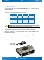
This manual describes the pITX-E38 boards made by KONTRON Technology A/S. In this manual the boards
will also be denoted E38.
The E38 boards are based on Intel Atom E38xx SoC (System on Chip) “Intel Bay Trail” and will be available
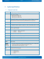
in three versions. The three types of boards are listed in this table:
Feature
!
pITX-E3815
pITX-E3826
pITX-E3845
Bay Trail SoC
E3815 (1 core) E3826 (2cores) E3845 (4 cores)
Kontron PN
810602-4500
810601-4500
810600-4500
Core speed
1,46GHz
1,46GHz
1,91GHz
Cooling (integrated)
Passive
Passive
Active
Battery module
Included
Included
Included
Total Design Power
5W
7W
10W
Warning: If changing the premounted cooling system, then the system might get overheated
resulting in instable system or defects if the cooling system is sufficient.
Use of this Users Guide implies a basic knowledge of PC-AT hard- and software. This manual is focused on
describing the E38 board’s special features and is not intended to be a standard PC-AT textbook.
New users are recommended to study the short installation procedure stated in the following chapter
before switching-on the power.
All configuration and setup of the CPU board is either done automatically or manually by the user via the
BIOS setup menus. Only exceptions are the “Clear CMOS” Jumper and the “Always On” jumper.
Latest revision of this manual, datasheet, BIOS, drivers, BSP’s (Board Support Packages), Mechanical
drawings (2D and 3D) can be downloaded from here:
http://www.kontron.com/products/boards-and-mezzanines/embedded-sbc/pitx-25-sbc/pitx-e38.html
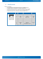
Battery Module:
PN 1055-7645
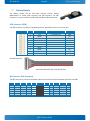
Active cooler:
pITX-E38 Users Guide
KTD-N0904-E
2
Page 6
Installation Procedure
Installation Procedure
2.1
Installing the Board
To get the board running follow these steps. If the board shipped from KONTRON has already components
like RAM and CPU cooler mounted, then relevant steps below can be skipped.
1. Turn off the PSU (Power Supply Unit)
!
Warning: Turn off PSU (Power Supply Unit) completely (no mains power connected to the PSU) or
leave the Power Connectors unconnected while configuring the board. Otherwise components
(RAM, LAN cards etc.) might get damaged. Make sure to use +5V single supply only. Alternatively
use a standard ATX PSU with suitable cable kit and PS_ON# active.
2. Insert the DDR3L SODIMM module
For a list of approved DDR3L SODIMMs contact your Distributor or FAE. See also chapter “System Memory
Support”.
3. Cooler Installation
Normally the cooler is premounted, but in case not, then make sure the heat paste etc. on the cooler is
intact and cover the full area of the SoC. Connect Cooler Fan electrically to the FAN_CPU connector.
4. Connecting Interfaces
Insert all external cables for hard disk, keyboard etc. A monitor must be connected in order to change
BIOS settings.
5. Connect and turn on PSU
Connect PSU to the board by the +5Vin-Internal connector or the +5Vin-External connector. Please note
that current limitations apply, see relevant connector description.
6. Power Button
If the board does not start by itself when switching on the ATX PSU AC mains, then follow these
instructions to start the board. Install the Always On Jumper in the Always On position or toggle the
PWRBTN_IN# signal (available in the FRONTPNL connector), by momentary shorting pins 2 (PWRBTN_IN#)
and pin 4 (GND). A “normally open” switch is recommended.
7. BIOS Setup
Enter the BIOS setup by pressing the <F2> key during boot up.
Enter “Exit Menu” and Load Setup Defaults.
Refer to the “BIOS Configuration / Setup“ section of this manual for details on BIOS setup. Please note
that BIOS may boot in UEFI shell, if so then type exit to activate BIOS menu and select Set-up.
Note: To clear all BIOS settings, including Password protection, activate “Clear CMOS Settings” Jumper
for ⋲10 sec (without power connected).
pITX-E38 Users Guide
KTD-N0904-E
Page 7
Installation Procedure
8. Mounting the board in chassis
!
Warning: When mounting the board to chassis etc. please notice that the board contains
components on both sides of the PCB which can easily be damaged if board is handled without
reasonable care. A damaged component can result in malfunction or no function at all.
When fixing the Motherboard on a chassis it is recommended using screws with integrated washer and a
diameter of ⋲7mm. Do not use washers with teeth, as they can damage the PCB and cause short circuits.
2.2
Requirements IEC60950
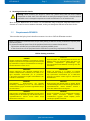
Take care when designing chassis interface connectors in order to fulfil the IEC60950 standard.
When an interface or connector has a VCC (or other power) pin which is directly connected to a power plane
like the VCC plane:
To protect the external power lines of the peripheral devices the customer has to ensure:
• Wires have suitable rating to withstand the maximum available power.
• That the enclosure of the peripheral device fulfils the fire protecting requirements of IEC60950.
Lithium battery precautions
CAUTION!
Danger of explosion if battery is incorrectly re- placed.
Replace only with same or equivalent type recommended
by manufacturer. Dispose of used batteries according to
the manufacturer’s instruc- tions.
VORSICHT!
Explosionsgefahr bei unsachgemäßem Austausch der
Batterie. Ersatz nur durch den selben oder einen vom
Hersteller
empfohlenen
gleichwertigen
Typ.
Entsorgung gebrauchter Batterien nach Anga- ben des
Herstellers.
ATTENTION!
Risque d'explosion avec l'échange inadéquat de la
batterie. Remplacement seulement par le même ou un
type équivalent recommandé par le producteur.
L'évacuation des batteries usagées conformément à des
indications du fabricant.
PRECAUCION!
Peligro de explosión si la batería se sustituye
incorrectamente. Sustituya solamente por el mismo o
tipo equivalente recomendado por el fabricante.
Disponga las baterías usadas según las instrucciones
del fabricante.
ADVARSEL!
Lithiumbatteri – Eksplosionsfare ved fejlagtig
håndtering. Udskiftning må kun ske med batteri af
samme fabrikat og type. Levér det brugte batteri tilbage
til leverandøren.
ADVARSEL!
Eksplosjonsfare ved feilaktig skifte av batteri. Benytt
samme batteritype eller en tilsvarende type anbefalt av
apparatfabrikanten. Brukte batterier kasseres i
henhold til fabrikantens instruksjoner.
VARNING!
Explosionsfara vid felaktigt batteribyte. Använd samma
batterityp eller en ekvivalent typ som rekommenderas av
apparattillverkaren. Kassera använt batteri enligt
fabrikantens instruktion.
VAROITUS!
Paristo voi räjähtää, jos se on virheellisesti asennettu.
Vaihda paristo ainoastaan lalteval- mistajan
suosittelemaan tyyppiln. Hävitä käytetty paristo
valmistajan ohjeiden mukaisesti.
pITX-E38 Users Guide
KTD-N0904-E
3
Page 8
System Specification
System Specifications
3.1
Component main data
Form factor
pITX (picoITX) 100 mm by 72 mm
Processor
Intel Bay Trail FCBGA1170 Type 3 27x25mm 0.593 Ball Pitch.
Three versions available:
E3815 (1 core), 1,46GHz, 5W
E3826 (2 core), 1,46GHz, 7W
E3845 (4 core), 1,91GHz, 10W
Memory
1x DDR3L SODIMM socket supporting single-channel unbuffered DDR3L 1066/1333MHz
(PC3-8500/PC3-10600). pITX-E3815/E3826 supports only DDR3-1066MHz. Up to 4GB
(Intel specification) however Kontron has qualified 8GB. (ECC not supported).
Lan
1x Gbe LAN Intel I210 ”Springville”
DP
DP (DisplayPort) v1.1a
Intel® Gen7 Graphics, OpenGL 3.0, OpenCL 1.2, DX11, H.264, MPEG2, MCV, VC-1, VP8
LVDS
LVDS panels up to 2 pixels per clock, 24 bit colors (VESA/JEIDA). Based on DP to LVDS
converter type PTN3460BS.
•
•
•
USB
1x USB3.0/2.0 (IO area, lower port)
1x USB2.0
(IO area, upper port)
2x USB2.0
(internal)
Serial
2x Serial ports (RS232) (TTL only) on internal 5-pin connector
Sata
1x SATA2.0
GPIO
10 x GPIOs (General Purpose I/Os), (via GPIO connector)
MicroSD Card
1x MicroSD Card Slot
mPCIe or
mSATA
1x mPCIe (miniPCI Express) or 1x mSATA (miniSATA). Full- or halfsize formfactor. (No
USB included)
Hardware
Monitor
Subsystem
•
•
•
Power Supply
Unit
+5V single supply via either Vin-Int. (4-pin connector) or Vin-Ext. connector (DC
Connector RA 2mm locking type)
Audio
HDA Codec IDT 92HD73C1T5PRGIC1X8:
• 1x Stereo Line in
• 1x Stereo Line out
• 1x Mic in
Fan control system support Thermal cruise (fixed temperature limit, no BIOS setup).
Thermal inputs: PCB near SoC temperature (precision +/- 3ºC).
System temperature sensor (precision +/- 0.5ºC)
pITX-E38 Users Guide
KTD-N0904-E
Environmental
Conditions
Page 9
System Specification
Operating:
-25ºC to 75ºC operating temperature. It is the customer’s responsibility to provide
sufficient airflow around each of the components to keep them within allowed
temperature range.
10% to 90% relative humidity (non-condensing)
Storage:
-20°C to 70°C; lower limit of storage temperature is defined by specification
restriction of on-board BR2032 battery. Board with battery has been verified for
storage temperature down to -40°C by Kontron.
5% to 95% relative humidity (non-condensing)
Electro Static Discharge (ESD) / Radiated Emissions (EMI):
All Peripheral interfaces intended for connection to external equipment are ESD/ EMI
protected.
EN 61000-4-2:2000 ESD Immunity
EN55022:2006+A1:2007 class B Generic Emission Standard.
Safety:
IEC 60950-1: 2005, 2nd Edition
UL 60950-1
CSA C22.2 No. 60950-1
Product Category: Information Technology Equipment Including Electrical Business
Equipment
Product Category CCN: NWGQ2, NWGQ8
File number: E194252
Shock:
IAW IEC 60068-2-27, Test Ea, shock, 18 shocks 3 per axis, 6 directions.
Shock pulse 50g, 11ms halfsine.
Bump:
IAW IEC 60068-2-29, Test Eb, Bump, 3000 bumps, 500 per axis, 6 directions.
Half Sine Waveform Acceleration 2g; Pulse Duration 11ms.
Vibration:
IAW IEC 60068-2-64, Test Fh, Random Vibration. 90 min per axis, 3 axes, at 1.9 grms,
with PSD: 10-20 Hz: 0.05 g²/Hz and 20-500 Hz: -3dB/octave.
Theoretical MTBF:
414.670 / 183.190 hours @ 40°C / 75°C. Note that these values are without the active
cooler used on the pITX-E3845 (see next page).
Restriction of Hazardous Substances (RoHS):
All boards in the pITX-E38 family are RoHS compliant.
Capacitor utilization:
Solid Capacitors with Conductive Polymer rated for 105 °C used on board.
pITX-E38 Users Guide
KTD-N0904-E
Battery
(via Battery
Module)
Page 10
System Specification
Battery Module PN 1055-7645. Contains exchangeable 3.0V Lithium battery for onboard Real Time Clock and CMOS RAM.
Manufacturer Panasonic / Part-number BR-2032BN.
Approximate 7.2 years retention.
Current draw is typical less than 3 µA when PSU is disconnected and 0 µA in S0 – S5.
Note that if BR-2032BN is replaceable by CR2032 type Panasonic CR-2032L/BN,
CR2032N/BN or CR-2032L/BE, then operating temperature range is -25ºC to 60ºC and
storage temperature range is-20ºC to 60ºC and approximate 8.8 years retention.
Note that Intel specifies that battery must be connected, however it is unspecified what
is the risk of not using battery. When battery is not connected, Kontron has not been
able to find any problems except for RTC not running.
CAUTION: Danger of explosion if the battery is incorrectly replaced. Replace only
with the same or equivalent type recommended by the manufacturer. Dispose of
used batteries according to the manufacturer’s instructions.
Cooler
The Cooler heatspreader is passive on the pITX-E3815 and pITX-E3826, so no fan is
included.
The Cooler heatspreader is active on the pITX-E3845, so the cooler has integrated fan
(UL-approved) with the following specifications:
Supply Voltage: 4.5V – 5.5V
Startup Voltage: 4.0V
Rotation Speed, rated: 5000 RPM
Noise level, maximum: 27.0 dB(A)
MTBF: 70000 Hours @ 40°C
Operating Temperature: -25°C to +90°C
pITX-E38 Users Guide
KTD-N0904-E
3.1
Page 11
System Specification
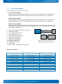
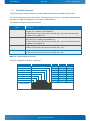
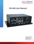
System overview
The block diagram below shows the architecture and main components of the pITX-E38. The key component
on the board is the Intel® Atom E38xx SoC (Bay Trail).
DP (DisplayPort 1.1),
LVDS (2 pixel/clock, 24 bit):
DP + LVDS
1x USB3.0/2.0 (IO area)
1x USB2.0
(IO area)
2x USB2.0
(internal)
SODIMM DDR3L 1066/1333
1 slot 1-8GB.
Intel
Atom
E3815/26/
45
System on
Chip
mSATA or mPCIe (no USB)
1x SATA 2.0
MicroSD Card slot
1x LAN GbE (Intel Pearsonville)
10/100/1000Mb
SPI BIOS Flash (64MBit)
SPI Header
Audio Codec 2HD73C1T5PRGIC1X8:
Line-In, Line-Out & Mic
2x COM (RS232, TTL level)
Hardware Monitor NCT7802Y:
Fan
SoC temperature
10x GPIO
System temperature (LM75)
3.2
Integrated premounted cooler
Passive cooler on the pITX-E3815 and pITX-E3826
Active cooler on the pITX-E3845
pITX-E38 Users Guide
KTD-N0904-E
3.1
Page 12
System Specification
System Memory Support
The pITX-E38 has 1x DDR3L SODIMM 204 pin socket supporting single-channel unbuffered
DDR3L 1066/1333MHz (PC3L-8500/PC3L-10600). pITX-E3815/E3826 supports only
DDR3-1066MHz. Up to 4GB (Intel specification) however Kontron has qualified 8GB.
(ECC not supported).
Note:
If using 32bit OS then less than 4GB in displayed in System Properties
(Shared Video Memory/PCI resources is subtracted, Windows 32b report 2.88GB free)
Kontron offers the following memory modules for support of the temperature range -25⁰C to 75⁰C:
P/N 1055-9445: 1GB DDR3L 1600 PC3L-12800
P/N 1055-9446: 2GB DDR3L 1600 PC3L-12800
P/N 1055-9447: 4GB DDR3L 1600 PC3L-12800
P/N 1055-9448: 8GB DDR3L 1600 PC3L-12800
Kontron offers the following memory modules for support of the temperature range 0⁰C to 60⁰C:
P/N 1055-9939: 2GB DDR3L 1600 PC3L-12800
P/N 1055-9941: 4GB DDR3L 1600 PC3L-12800
P/N 1055-9942: 8GB DDR3L 1600 PC3L-12800
Memory modules have in general a much lower longevity than embedded motherboards, and therefor EOL
of modules can be expected several times during lifetime of the motherboard. Kontron guarantees that the
above P/N will be maintained so that EOL module will be replaced by other similar type of qualified module.
As a minimum it is recommend using Kontron memory modules for prototype system(s) in order to prove
stability of the system and as for reference.
For volume production you might request to test and qualify other types of RAM. In order to qualify RAM it
is recommend configuring 3 systems running RAM Stress Test program in heat chamber at 60⁰C or 75⁰C
(depending on the requested maximum temperature) for a minimum of 24 hours.
pITX-E38 Users Guide
KTD-N0904-E
3.2
Page 13
System Specification
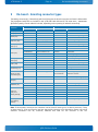
Power Consumption
The following items were used in the test setup:
1. Low Power Setup (E3815):
Standard system configuration equipped withInternal graphics, 1x 500GB SATA disk, mSATA 40GB, 1x
SODIMM (2GB Modules), DP Monitor, USB Keyboard & Mouse. 1x 8GB USB2.0 Stick, 1x LAN Gigabit.
Mid Power Setup (E3826):
Standard system configuration equipped withInternal graphics, 1x 500GB SATA disk, mSATA 40GB, 1x
SODIMM (4GB Modules), DP Monitor, USB Keyboard & Mouse. 2x 8GB USB2.0 Stick,1x LAN Gigabit.
High Power Setup (E3845):
Standard system configuration equipped withInternal graphics, 1x 500GB SATA disk, mSATA 40GB, 1x
SODIMM (8GB Modules), DP Monitor, LVDS, USB Keyboard & Mouse. 2x 8GB USB2.0 Stick,1x 16GB
USB3.0 Stick,1x LAN Gigabit.
2.
3.
4.
5.
6.
7.
8.
9.
10.
11.
12.
13.
Active cooler (High & Mid), Passive cooler (Low)
USB Keyboard/Mouse
2.5” SATA HDD external power.
Agilent E3634A @ 5V, 4A
Lecroy SDA820Zi-A Oscilloscope
Lecroy AP015 Current Probe
USB Flash 1x 8GB USB 2.0
USB Flash 1x 16GB USB 3.0
DP Monitor 1200x1600
LVDS Display 1200x1600
mSATA: 40GB
Memory: 8/4/2 GB SODIMM 1333 PC3-10600
Gnd
pITX-E38
+5V
PSU
+5V
Current
probe
Tektronix
TDS5104B
Note that power consumption of the
Display and HDD are not included.
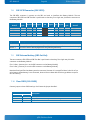
Power measurrements:
Low Power Setup (E3815)
Mid Power Setup (E3826)
DOS Idle
760mA - 3.8W
935mA - 4.675W
Windows 7, 3DMARK AE (first scene) +Burn in test 7.1
1320mA - 6.6W
1810mA - 9.05W
Windows 7, idle, desktop, no applications running
848mA - 4.24W
1130mA - 5.65W
S3 Mode
247mA - 1.235W
255mA - 1.275W
S4 Mode
239mA - 1.195W
238mA - 1.19W
S5 Mode
214mA - 1.070W
219mA - 1.095W
pITX-E38 Users Guide
High Power Setup (E3845)
1150mA - 5.75W
2270mA - 11.35W
1250mA - 6.25W
266mA - 1.33W
236mA - 1.18W
228mA - 1.14
KTD-N0904-E
4
Page 14
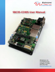
Connector Locations
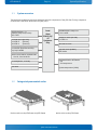
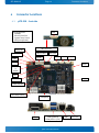
Connector Locations
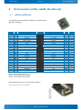
pITX-E38 - frontside
4.1
On the backside:
SODIMM
MicroSD Card Slot
System Temp. Sensor
XDP (unsupported)
GPIO
SBC connector
Always On
SBC-Ext-Bat
Clear CMOS
SBC-GPIO
SPI
SATA0
USB3
COM2
COM1
USB2
Audio
mPCIe
or
mSATA
Fan
+5Vin Int.
LVDS
Power OK LED
SoC Temp. Sensor
Frontpanel
DP1
USB1 (USB2.0)
USB0 (USB 3.0/2.0)
pITX-E38 Users Guide
LAN1
5Vin Ext.
KTD-N0904-E
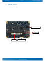
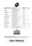
4.2
Page 15
Connector Locations
pITX-E38 - backside
System Temp. Sensor
MicroSD Card
SODIMM
XDP (unsupported)
pITX-E38 Users Guide
KTD-N0904-E
5
Page 16
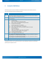
Connector Definitions
Connector Definitions
The following sections provide pin definitions and detailed description of all on-board connectors.
The connector definitions follow the following notation:
Column
name
Description
Pin
Shows the pin-numbers in the connector. The graphical layout of the connector definition
tables is made similar to the physical connectors.
Signal
The mnemonic name of the signal at the current pin. The notation “XX#” states that the signal
“XX” is active low.
Type
AI:
AO:
I:
IO:
IOT:
IS:
IOC:
IOD:
NC:
O:
OC:
OT:
LVDS:
PWR:
Analogue Input.
Analogue Output.
Input, TTL compatible if nothing else stated.
Input / Output. TTL compatible if nothing else stated.
Bi-directional tristate IO pin.
Schmitt-trigger input, TTL compatible.
Input / open-collector Output, TTL compatible.
Input / Output, CMOS level Schmitt-triggered. (Open drain output)
Pin not connected.
Output, TTL compatible.
Output, open-collector or open-drain, TTL compatible.
Output with tri-state capability, TTL compatible.
Low Voltage Differential Signal.
Power supply or ground reference pins.
Ioh: Typical current in mA flowing out of an output pin through a grounded load, while the
output voltage is > 2.4 V DC (if nothing else stated).
Iol: Typical current in mA flowing into an output pin from a VCC connected load, while the
output voltage is < 0.4 V DC (if nothing else stated).
Pull U/D
On-board pull-up or pull-down resistors on input pins or open-collector output pins.
Note
Special remarks concerning the signal.
The abbreviation TBD is used for specifications which are not available yet or which are not sufficiently
specified by the component vendors.
pITX-E38 Users Guide
KTD-N0904-E
6
6.1
Page 17
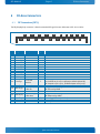
IO-Area Connectors
IO-Area Connectors
DP Connectors (DP1)
The DP (DisplayPort) connector is based on standard DP type Foxconn 3VD51203-H7JJ-7H or similar.
19
20
Pin
1
2
3
4
5
6
7
8
9
10
11
12
Config1
14
Config2
16
17
18
19
20
18
15
16
Signal
Description
Lane 0 (p)
GND
Lane 0 (n)
Lane 1 (p)
GND
Lane 1 (n)
Lane 2 (p)
GND
Lane 2 (n)
Lane 3 (p)
GND
Lane 3 (n)
13
15
17
Aux or DDC
selection
(Not used)
Aux Channel (+)
Aux Ch (p)
or DDC Clk
GND
Aux Channel (-)
Aux Ch (n)
or DDC Data
Hot Plug
Return
3.3V
13
14
11
12
9
10
7
8
5
6
3
4
1
2
Type Note
LVDS
PWR
LVDS
LVDS
PWR
LVDS
LVDS
PWR
LVDS
LVDS
PWR
LVDS
Internally pull down (1Mohm).
I
Aux channel on pin 15/17 selected as default (when NC)
DDC channel on pin 15/17, If HDMI adapter used (3.3V)
O
Internally connected to GND
AUX (+) channel used by DP
DDC Clk used by HDMI
PWR
AUX (-) channel used by DP
DDC Data used by HDMI
I
Internally pull down (100Kohm).
PWR Same as GND
PWR Fused by 1.5A resetable PTC fuse.
pITX-E38 Users Guide
KTD-N0904-E
6.2
Page 18
IO-Area Connectors
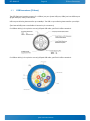
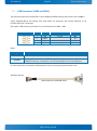
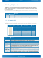
Ethernet Connector
The pITX-E38 support single channels of 10/100/1000Mb Ethernet based on Intel® Springville i210.
In order to achieve the specified performance of the Ethernet port, Category 5 twisted pair cables must be
used with 10/100MB and Category 5E, 6 or 6E with 1Gb LAN networks.
The signals for the Ethernet ports are as follows:
Signal
Description
MDI[0]+ / MDI[0]-
In MDI mode, this is the first pair in 1000Base-T, i.e. the BI_DA+/- pair, and is the
transmit pair in 10Base-T and 100Base-TX.
In MDI crossover mode, this pair acts as the BI_DB+/- pair, and is the receive pair
in 10Base-T and 100Base-TX.
MDI[1]+ / MDI[1]-
In MDI mode, this is the second pair in 1000Base-T, i.e. the BI_DB+/- pair, and is
the receive pair in 10Base-T and 100Base-TX.
In MDI crossover mode, this pair acts as the BI_DA+/- pair, and is the transmit pair
in 10Base-T and 100Base-TX.
MDI[2]+ / MDI[2]-
In MDI mode, this is the third pair in 1000Base-T, i.e. the BI_DC+/- pair.
In MDI crossover mode, this pair acts as the BI_DD+/- pair.
MDI[3]+ / MDI[3]-
In MDI mode, this is the fourth pair in 1000Base-T, i.e. the BI_DD+/- pair.
In MDI crossover mode, this pair acts as the BI_DC+/- pair.
Note: MDI = Media Dependent Interface.
The pinout of the RJ45 connectors is as follows:
Signal
MDI0+
MDI0MDI1+
MDI2+
MDI2MDI1MDI3+
MDI3Flashing =>
communication
PIN
Type
Ioh/Iol
On => 1GB link
8
7
6
5
4
3
2
1
pITX-E38 Users Guide
Note
KTD-N0904-E
6.1
Page 19
IO-Area Connectors
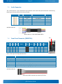
USB Connectors (IO Area)
The pITX-E38 board contains support for 1 USB3.0/2.0 port (Lower USB port, USB0) and one USB2.0 port
(higher USB port, USB1) in the IO area.
USB 2.0 ports allowing data transfers up to 480Mb/s. The USB 3.0 port allowing data transfers up to 5Gb/s.
(Two internal USB ports are available via internal 4-pin connectors)
For USB2.0 cabling it is required to use only HiSpeed USB cable, specified in USB2.0 standard:
For USB3.0 cabling it is required to use only HiSpeed USB cable, specified in USB3.0 standard:
pITX-E38 Users Guide
KTD-N0904-E
Page 20
IO-Area Connectors
USB Ports 0 and 1 are mounted together, USB1 (USB2.0) on top of the USB0 (USB3.0/USB2.0).
Note
1
1
Type
Signal
PIN
Signal
Type
IO
PWR
PWR
USB1- USB1+
5V/SB5V
1 2 3 4 GND
nc 5 6 7 8 9 nc
nc
nc
GND
IO
PWR
-
IO
PWR
IO
IO
PWR
USB0- USB0+
5V/SB5V
1 2 3 4 GND
RX0- 5 6 7 8 9 TX0+
RX0+
TX0GND
IO
PWR
IO
IO
Note
Note 1: In order to meet the requirements of USB standard, the 5V input supply must be at least 5.00V.
Signal
USBn+ USBnRXn+ RXnTXn+ TXn(n= 0,1)
5V/SB5V
Description
Differential pair works as serial differential receive/transmit data lines.
5V supply for external devices. SB5V is supplied during power-down to allow wakeup
on USB device activity. Protected by 1.0A current limiting circuit for each USB port.
pITX-E38 Users Guide
KTD-N0904-E
6.2
Page 21
IO-Area Connectors
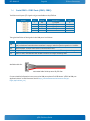
DC Power Jack Connector (5Vin Ext.)
Either the DC Power Jack Connector (5Vin Ext.) or the “5Vin Int.” connector must be used to supply the
board with +5V +/-5%.
The 5Vin Ext. power connector has Vin to the center pin and mates with Ø 6.3 mm DC Power jack with Ø 2.0
mm pin hole. (DC Connector RA 2mm locking type). Maximum allowed current is 5A.
Warning: Hot Plugging power supply is not supported. Hot plugging might damage the board.
Notes:
To protect the external power lines of peripheral devices make sure that
- the wires have the right diameter to withstand the maximum available current.
- to enclosure of the peripheral device fulfills the fire-protecting conditions of IEC/EN 60950.
pITX-E38 Users Guide
KTD-N0904-E
7
Page 22
IO-Area Connectors
Internal Connectors
7.1
Internal Power Connector (Vin Int.)
Header
Pin
1
2
3
4
Signal
+5V
+5V
GND
GND
Description
+5V power input
+5V power input
Power Ground
Power Ground
Type
PWR
PWR
PWR
PWR
Maximum allowed current on each pin is 3A.
Available cable kit:
1055-8061 Cable Power 4p 30cm OE pITX-E38
7.2
Fan Connector (Fan)
The Fan can be used to actively cool the heatsink mounted on the board. The fan rotation speed can be
monitored and the fan speed controlled by the temperature of the PCB (near SoC).
Header
Signal
PWM
TACHO
GND
Pin
1
2
3
Signal
TACHO
PWM
GND
Description
Rotation speed
PWM output
Ground
Type
I
O-5V
PWR
Description
PWM output signal for FAN speed control.
Tacho input signal from the fan, for rotation speed supervision RPM (Rotation Per Minute). The
signal shall be generated by an open collector transistor or similar. Onboard is a pull-up
resistor 2K2 to +3.3V. The signal has to be pulsed and onboard circuit is prepared for two
pulses per rotation.
Power Supply GND signal
pITX-E38 Users Guide
KTD-N0904-E
7.1
Page 23
IO-Area Connectors
LVDS Flat Panel Connector (LVDS)
The LVDS connector is based on 40 pole connector type Samtec SHF-120-01-F-D-SM-K-TR or similar.
Note
Max. 0.5A
Max. 0.5A
Max. 0.5A
Max. 0.5A
Max. 0.5A
2K2Ω, 3.3V
3.3V level
3.3V level
Type
Signal
PWR
+5V
PWR
+5V
PWR
+5V
PWR
+5V
PWR
LCDVCC
OT
DDC CLK
OT
BKLTCTL
OT
BKLTEN#
LVDS LVDS A0LVDS LVDS A1LVDS LVDS A2LVDS LVDS ACLKLVDS LVDS A3Max. 0.5A PWR
GND
LVDS LVDS B0LVDS LVDS B1LVDS LVDS B2LVDS LVDS BCLKLVDS LVDS B3Max. 0.5A PWR
GND
PIN
1 2
3 4
5 6
7 8
9 10
11 12
13 14
15 16
17 18
19 20
21 22
23 24
25 26
27 28
29 30
31 32
33 34
35 36
37 38
39 40
Signal
+5V
+5V
GND
GND
LCDVCC
DDC DATA
VDD ENABLE
GND
LVDS A0+
LVDS A1+
LVDS A2+
LVDS ACLK+
LVDS A3+
GND
LVDS B0+
LVDS B1+
LVDS B2+
LVDS BCLK+
LVDS B3+
GND
Type
PWR
PWR
PWR
PWR
PWR
OT
OT
PWR
LVDS
LVDS
LVDS
LVDS
LVDS
PWR
LVDS
LVDS
LVDS
LVDS
LVDS
PWR
Note
Max. 0.5A
Max. 0.5A
Max. 0.5A
Max. 0.5A
Max. 0.5A
2K2Ω, 3.3V
3.3V level
Max. 0.5A
Max. 0.5A
Max. 0.5A
Note: The LVDS connector supports single and dual channel, 18/24bit SPWG panels up to a resolution of
1600x1200 or 1920x1080 and with limited frame rate up to 1920x1200.
Signal
LVDS A0..A3
LVDS ACLK
LVDS B0..B3
LVDS BCLK
BKLTCTL
BKLTEN#
VDD ENABLE
LCDVCC
DDC CLK
Description
LVDS A Channel data
LVDS A Channel clock
LVDS B Channel data
LVDS B Channel clock
Backlight control (1), PWM signal to implement voltage in the range 0-3.3V
Backlight Enable signal (active low) (2)
Output Display Enable.
VCC supply to the display. 5V or 3.3V (1A Max.) selected in BIOS setup menu. Power
sequencing depends on LVDS panel selection. (Shared with eDP connector)
DDC Channel Clock
Notes: Windows API will be available to operate the BKLTCTL signal. Some Inverters have a limited voltage
range 0- 2.5V for this signal: If voltage is > 2.5V the Inverter might latch up. Some Inverters
generates noise on the BKLTCTL signal, causing the LVDS transmission to fail (corrupted picture on
the display). By adding a 1Kohm resistor in series with this signal, mounted at the Inverter end of
the cable kit, the noise is limited and the picture is stable.
If the Backlight Enable is required to be active high then, check the following BIOS Chipset setting:
Backlight Signal Inversion = Enabled.
Available cable kit:
821515 Open End LVDS Cable 572mm
pITX-E38 Users Guide
KTD-N0904-E
7.2
Page 24
IO-Area Connectors
SATA (Serial ATA) Disk interface (SATA0)
Sata0 connector pinning:
PIN
Signal
Type
1
2
3
4
5
6
7
GND
SATA* TX+
SATA* TXGND
SATA* RXSATA* RX+
GND
PWR
-
PWR
-
PWR
-
Signal
SATA0 RX+ / RXSATA0 TX+ / TX-
Ioh/Iol Note
Description
Host transmitter differential signal pair
Host receiver differential signal pair
Available cable kit:
PN 96079-0000-00-1 Cable SATA 500mm
pITX-E38 Users Guide
KTD-N0904-E
7.3
Page 25
IO-Area Connectors
USB Connectors (USB2 and USB3)
The pITX-E38 support two internal USB 2.0 ports (USB2 and USB3) allowing data transfers up to 480Mb/s.
Legacy Keyboard/Mouse and wakeup from sleep states are supported. Over-current detection on all
fourteen USB ports is supported.
See chapter “USB Connectors (IO Area)” for more information on USB0 – USB1.
Header
Pin
1
2
3
4
Signal
GND
USBx+
USBx5V/SB5V
Description
Ground
5V power
Type
PWR
IO
IO
PWR
Note1:
Signal
USBx+ USBx5V/SB5V
Description
Differential pair works as Data/Address/Command Bus.
5V supply for external devices. SB5V is supplied during powerdown to allow wakeup on
USB device activity. Protected by 1.0A current limiting circuit for each USB port.
In order to meet the requirements of USB standard, the 5V input supply must be at least 5.00V.
Available cable kit:
96054-0000-00-2 Cable KAB-USB-2
pITX-E38 Users Guide
KTD-N0904-E
7.4
Page 26
IO-Area Connectors
Serial COM1 – COM2 Ports (COM1, COM2)
Two RS232 serial ports (TTL signals only) are available on the pITX-E38.
Header
Pin
1
2
3
4
5
Signal
TxD
RxD
RTS
CTS
GND
Description
TTL signal
TTL signal
TTL signal
TTL signal
Ground
Type
O
I
O
I
PWR
The typical definition of the signals in the COM ports is as follows:
Signal
Description
TxD
Transmitted Data, sends data to the communications link. The signal is set to the marking state
(0V) on hardware reset when the transmitter is empty or when loop mode operation is initiated.
RxD
Received Data, receives data from the communications link.
RTS
Request To Send, indicates to the modem etc. that the on-board UART is ready to exchange data.
CTS
Clear To Send, indicates that the modem or data set is ready to exchange data.
Available cable kit:
1055-8059 Cable Serial 5p 20cm OE pITX-E38
For more detailed information how to set up the COM ports please find KTD-N0914 “pITX-E38 COM port
Application Note” on EMD Customer Section http://emdcustomersection.kontron.com/wplogin.php?redirect_to=/
pITX-E38 Users Guide
KTD-N0904-E
7.5
Page 27
IO-Area Connectors
Audio Connector
The on-board Audio circuit implements High Definition Audio with UAA (Universal Audio Architecture),
featuring 24-bit stereo DAC and 20-bit stereo ADCs.
Header
Pin
1
2
3
4
5
6
Signal
Line-in left
Mic
Line-in right
Line-out left
GND
Line-out right
Description
Type
O
I
O
I
PWR
O
Microphone
Ground
Available cable kit:
96063-0000-00-1 Cable KAB-SOUND-CMP-2
7.6
Note
1
Pin 1
Front Panel Connector (FRONTPNL)
Pull Ioh/
Ioh/ Pull
Type
Signal
PIN
Signal Type
U/D Iol
Iol
U/D
I
PWRBTN_IN# 2 1 RSTIN#
I
- PWR
Gnd
4 3
GND
PWR
- PWR
5V
6 5
Beep
220R O
3.3V
8 7
3.3V
O
220R
O
SuspendLED 10 9 SataLED# O
-
Note
1
Note1, LED output has integrated 220 ohm.
Signal
RSTIN#
PWRBTN_IN#
Beep
+5V
3.3V
SATA_LED#
SUS_LED
Description
Reset Input active low.
Power Button In. Toggle this signal low to boot the board or to shut down.
5V maximum load is 500mA.
3.3V signal via 220 ohm resistor pullup to 3.3V.
SATA Activity LED (active low signal). 3V3 output when passive.
Suspend Mode LED (active high signal). Output 3.3V via 220Ω.
Available cable kit:
1055-8065 Cable Frontpanel 10p 20cm OE pITX-E38
pITX-E38 Users Guide
KTD-N0904-E
7.7
Page 28
IO-Area Connectors
Battery Module
The battery module PN PN 1055-7645 contains Lithium battery
BR2032/BN in a socket, GPIO connector and SBC-Connector. The SBC
Connector is used to interface the SBC-GPIO and SBC-Ext-Bat connectors.
GPIO Connector (GPIO)
The GPIO connector is present on the Battery Module, type Molex 53261-1071 (or similar).
Header
Pin
1
2
3
4
5
6
7
8
9
10
Signal
3.3V
GPIO0
GPIO1
GPIO2
GPIO3
GPIO4
GPIO5
GPIO6
GPIO7
GND
Description
3.3V Power Out
Ground
Type
PWR
IOT
IOT
IOT
IOT
IOT
IOT
IOT
IOT
PWR
Available cable kit:
1055-8063 Cable GPIO 10p 20cm OE pITX-E38
SBC Connector (SBC-Connector)
The SBC connector is present on the Battery Module and used to interface the Battery Module to the SBC.
Note Pull U/D Ioh/Iol Type
TBD
IOT
TBD
IOT
TBD
IOT
TBD
IOT
PWR
Signal
BatGPIO7
GPIO5
GPIO3
GPIO1
3.3V
PIN
2 1
4 3
6 5
8 7
10 9
12 11
Signal
Bat+
GND
GPIO6
GPIO4
GPIO2
GPIO0
Type Ioh/Iol Pull U/D Note
PWR
IOT
TBD
IOT
TBD
IOT
TBD
IOT
TBD
-
pITX-E38 Users Guide
KTD-N0904-E
Page 29
IO-Area Connectors
SBC-GPIO Connector (SBC-GPIO)
7.8
The SBC-GPIO connector is present on the SBC and used to interface the Battery Module. The two
connectors SBC-GPIO and SBC-Ext-Bat is positioned so that they fit a single 2x6 pin header connector on
the Battery Module.
Battery
Module
SBC-12
SBC-10
SBC-8
SBC-6
SBC-4
Signal
Pull
U/D
-
Ioh/Iol Type Signal
TBD
TBD
TBD
TBD
PWR
IOT
IOT
IOT
IOT
3.3V
GPIO1
GPIO3
GPIO5
GPIO7
PIN
1
3
5
7
9
2
4
6
8
10
Signal Type Ioh/Iol
GPIO0 IOT
GPIO2 IOT
GPIO4 IOT
GPIO6 IOT
GND PWR
TBD
TBD
TBD
TBD
-
Pull
U/D
-
Battery
Module
SBC-11
SBC-9
SBC-7
SBC-5
SBC-3
Description
3.3V
GPIO0..7
7.9
General Purpose Inputs / Output. These Signals may be controlled or monitored through
the use of the KT-API-V2 (Application Programming Interface).
SBC-External battery (SBC-Ext-Bat)
The two connectors SBC-GPIO and SBC-Ext-Bat is positioned so that they fit a single 2x6 pin header
connector on the Battery Module.
Pin 1 is Bat+, (same as pin 1 on the SBC connector on the Battery Module)
Pin 2 is Bat-, (same as pin 2 on the SBC connector on the Battery Module)
Note that Intel specifies that battery must be connected, however it is unspecified what is the risk of not
using battery. When battery is not connected, Kontron has not been able to find any problems except for
RTC not running.
7.10 Clear CMOS (CLR-CMOS)
Connect jumper to clear CMOS settings. Don’t leave the jumper installed.
CMOS1
pin1-2
pin2-3
X
X
-
Description
Default position
Load Default BIOS Settings exclusive erasing Password
No function.
pITX-E38 Users Guide
KTD-N0904-E
Page 30
IO-Area Connectors
7.11 “Always On” (Always On)
The “Always On” can be used to implement hardware controlled Always ON by jumper. When “Always On” is
selected, then the board will power up automatically when power is connected. It doesn’t matter if “Always
On” is not selected in BIOS.
The board can still be shut down by PWRBTN_IN# (power button in) activation (via Front Panel connector).
Always On
pin1-2
pin2-3
X
X
-
Description
Always On selection
Default position
No function. Note: may load default BIOS settings after several minutes
7.12 SPI Connector (SPI)
The SPI (Serial Peripheral Interface) Bus connector provides synchronous full duplex in a 9 pin header.
Header
Signal
SPI_CLK
3.3V
Pin
1
2
3
4
5
6
7
8
9
Signal
GND
SPI_MISO
SPI_MOSI
SPI_CS#
SPI_CLK
NC
3.3V
ADDIN
ISOLATE#
Description
Ground
SPI master input, Slave Output
SPI master output, Slave Input
SPI slave select, active low
SPI clock
Not connected
3.3V Power
Disable onboard SPI flash
Disable the SPI interface
Type
PWR
IO-3.3
IO-3.3
O-3.3
O-3.3
NC
PWR
I-3.3
I-3.3
Description
Serial Clock
3.3V Standby Voltage power line. Normally output power, but when Motherboard is
turned off then the on-board SPI Flash can be 3.3V power sourced via this pin.
SPI_CS#
CS# Chip Select, active low.
ADDIN
ADDIN input signal must be NC.
SPI_MOSI
Master Output, Slave Input.
ISOLATE#
The ISOLATE# input, active low, is normally NC, but must be connected to GND when
programming the SPI flash. Power Supply to the Motherboard must be turned off when
loading SPI flash. The pull up resistor is connected via diode to 5VSB.
SPI_MISO
Master Input, Slave Output
SPI Data I/O: A bidirectional signal used to support Dual IO Fast Read, Quad IO Fast Read
SPI_IO2_#WP
and Quad Output Fast Read modes. The signal is not used in Dual Output Fast Read mode.
SPI Data I/O: A bidirectional signal used to support Dual IO Fast Read, Quad IO Fast Read
SPI_IO3_#HOLD
and Quad Output Fast Read modes. The signal is not used in Dual Output Fast Read mode.
pITX-E38 Users Guide
KTD-N0904-E
Page 31
IO-Area Connectors
7.13 XDP (XDP)
The XDP-CPU (Intel Debug Port for CPU) connector is not mounted and not supported. XDP connector layout
(pads) is located on the backside of PCB and is prepared for the Molex 52435-2671 (or 52435-2672).
Pin
Signal
Description
Type Pull Up/Down Note
1 OBSFN_A0
2 OBSFN_A1
3
GND
PWR
4
NC
NC
5
NC
NC
6
GND
PWR
7
NC
NC
8
NC
NC
9
GND
PWR
10
HOOK0
PMC_RSMRST#
11
HOOK1
PWRBTN#
12
HOOK2 PMC_CORE_PWROK
13
HOOK3
XDP_RTEST#
14
HOOK4
NC
15
HOOK5
NC
16
+1,8V
PWR
17
HOOK6
PLTRST#
18
HOOK7
1,8V_SYS_RESET#
19
GND
PWR
20
TDO
21
TRST#
22
TDI
23
TMS
24
NC
NC
25
GND
PWR
26
TCK0
pITX-E38 Users Guide
220R to 1,8V
-
-
50R to 1,8V
/50R
50R to 1,8V
50R to 1,8V
/50R
KTD-N0904-E
8
Page 32
Slot Connectors
Slot Connectors (mPCIe, mSATA, MicroSD card)
8.1
mPCIe or mSATA slot
The miniPCIe port support mPCIe, mSATA and LPC POST module.
(No USB is included).
Note
Type
NC
NC
1
PWR
PWR
3
O
O
PWR
PWR
PWR
PWR
PWR
PWR
PWR
PWR
Signal
WAKE#
NC
NC
CLKREQ#
GND
PCIE_mini CLK#
PCIE_mini CLK
GND
1
3
5
7
9
11
13
15
PIN
2
4
6
8
10
12
14
16
Signal
+3V3
GND
+1.5V
LPC_Frame#
LPC_AD3
LPC_AD2
LPC_AD1
LPC_AD0
Type
PWR
PWR
PWR
O
IO
IO
IO
IO
RST#_LPC
CLK_Debug
GND
PCIE_RXN
PCIE_RXP
GND
GND
PCIE_TXN
PCIE_TXP
GND
GND
+3V3 Dual
+3V3 Dual
GND
CLK_MPCIE
DATA_MPCIE
RST_MPCIE#
SEL_MSATA
17
19
21
23
25
27
29
31
33
35
37
39
41
43
45
47
49
51
18
20
22
24
26
28
30
32
34
36
38
40
42
44
46
48
50
52
GND
W_Disable#
RST#
+3V3 Dual
GND
+1.5V
SMB_CLK
SMB_DATA
GND
NC
NC
GND
NC
NC
NC
+1.5V
GND
+3V3 Dual
PWR
Note 1: 10K ohm pull-up to 3V3.
Note 2: 2K2 ohm pull-up to 3V3 Dual.
Note 2: 10K ohm pull-down to GND.
Recommended fixing tool is “Richco MDLSP1-08M-01”
http://portal.richco-inc.com/login
pITX-E38 Users Guide
Note
2
PWR
PWR
PWR
PWR
NC
NC
PWR
NC
NC
NC
PWR
PWR
PWR
KTD-N0904-E
8.2
Page 33
Slot Connectors
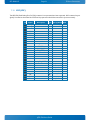
MicroSD card slot
SD Card 3.0 interface.
• Up to 832Mbits per second data rate using up to 4 parallel data lines.
• Transfers the data in following UHS-I modes: HS and DDR50.
• Cyclic Redundancy Check CRC7 for command and CRC16 for data integrity.
• Designed to work with I/O cards, Read-only cards and Read/Write cards.
• Supports Read wait Control. SDIO only validated with WIFI devices.
Header
9 1
8
Pin
1
2
3
4
5
6
7
8
9
10
11
Signal
CD / DATA3
CMD
GND
VCC3
CLK
GND
DATA0
DATA1
DATA2
CD#
WP
Description
Card detect / Data bit 3
Command line
Ground
Power +3.3V
Clock
Ground
Data bit 0
Data bit 1
Data bit 2
Card Detection on low
Write Protect
pITX-E38 Users Guide
Type
IO-3.3
IO-3.3
PWR
PWR
O-3.3
PWR
IO-3.3
IO-3.3
IO-3.3
I
I
KTD-N0904-E
9
Page 34
On-board and Mating connectors
On-board - & mating connector types
The Mating connector(s) / Cable Kits(s) which are fitting the On-board connectors are listed in below table.
The highlighted cable kits are included in the “pITX-E38 Cable & Driver Kit” PN 1056-2142 / 1000000021
(Different quantity of each cable kit included, depending on the quantity of onboard connectors).
Connector
FAN (J25)
XDP (J39)
SATA0 (J30)
+5Vin Int. (J24)
USB2 (J12)
USB3 (J11)
LVDS (J10)
COM1 (J21)
COM2 (J22)
Audio (J28)
Ext. Battery (J1)
On-board Connectors
Manufacturer
Type no.
MOLEX
53047-0310
MOLEX
52435-2671
Mating Connectors / Cables
Manufacturer
Type no.
LOTES
ABA-SAT-055-K03
Kontron
96079-0000-00-1 (cable)
JST
B4B-XH-A(LF)(SN)
Kontron
1055-8061 (cable)
MOLEX
53047-0410
Kontron
96054-0000-00-2 (cable)
EFCO
1250S-04TW
DON CONNEX
WIESON
TECHNOLOGIES
Hon Kon Technology
C44-40BSBC1-G
Don Connex
A32-40-C-G-B-1
G2124-03200101-00
Kontron
910000005
HB12-220-VFS-20R
Kontron
821515 (cable)
SAMTEC
SHF-120-01-F-D-SM-K-TR
Kontron
821155 (cable)
MOLEX
53261-0571
Kontron
1055-8059 (cable)
MOLEX
53261-0671
Kontron
96063-0000-00-1 (cable)
Wuerth Elektronik
62000211121
Kontron
Battery Module
W+P
314-010-002-XX
YIMTEX
3291*03SAGR(6T)
TE Connectivity
382575-3 (jumper)
TE Connectivity
382575-2 (jumper)
W+P
351-201-10-00/BF*2 (jumper)
Kontron
1055-8065 (cable)
Kontron
1055-8063 (cable)
Always On (J42)
Clear CMOS (J40)
SPI (J41)
FRONTPNL (J5)
GPIO (J2)
(2x6 pin to
Battery Module)
GPIO 10-pole
(from Battery
Module)
MOLEX
53261-0971
MOLEX
87759-1014
PLASTRON
PLASTRON
FCI
MOLEX
W+P
LTZ-10S2-B-C/D-F
LTZ-10S2-B-040/028-F
57102-F06-05ULF
0877581016
314-200-010-00
Molex
53261-1071
ACES ELECTRONIC
ACES ELECTRONIC
85204-10001
85204-10301
Note: In above table, more than one connector can be listed for each type of on-board connector, if they
all have same fit, form and function and are approved by Kontron as an alternative. Please notice that
standard connectors like DP, miniPCIe, Ethernet and USB are not included in the list.
pITX-E38 Users Guide
KTD-N0904-E
Page 35
BIOS - Main
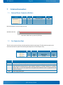
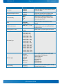
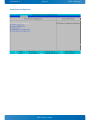
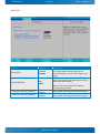
10 BIOS
The BIOS Setup is used to view and configure BIOS settings for the board. The BIOS Setup is accessed by
pressing the <Del>-key (<F2>-key on BIOS version v.16 or below) after the Power-On Self-Test (POST)
memory test begins and before the operating system boot begins.
From the EFI Shell write “Exit” followed by <TAB> and <Return> in order to enter BIOS Menu menu.
The BIOS settings will be loaded automatically when loading “Restore Default” see “Save & Exit” menu. In
this Users Guide the default settings are indicated by bold. Please notice that “Restore User Defaults”
might have different set of default values.
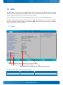
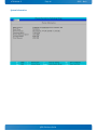
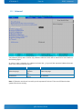
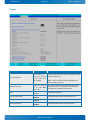
10.1 Main
Main
Advanced
Phoenix SecureCore Technology Setup
Security
Boot
Exit
Item Specific Help
BIOS Information
BIOS Vendor
Core Version
Compliancy Version
BIOS Version
Build Date and Time
Phoenix Technologies Ltd.
BTI_3.1.0.334.TXE1060.PVLV1019
UEFI 2.31; PI 1.20
21
Oct 30 2014 11:49:35
Board Information
Product Name
PCB ID
Serial Number
Part Number
Batch Number
Boot Count
pITX-E38
02
01243682
810601-4500
0D000000
6438
System Date
System Time
► System Information
► Boot Features
► Network Stack
F1
Esc
Help
Exit
View or set system date.
[07/07/2014]
[14:21:40]
↑↓
←→
Select Item
Select Menu
+/Enter
Change Values
Select ►Sub-Menu
F9
F10
Setup Defaults
Save and Exit
Sub Menu available.
White text for actual selected function which can be modified.
Blue text for functions (not all can be modified).
Black background for actual selection. Black text actual settings.
The following table describes the changeable settings:
Feature
Options
System Date
MM/DD/YYYY
System Time
HH:MM:SS
Description
Set the system date.
Set the system time.
pITX-E38 Users Guide
KTD-N0904-E
Page 36
BIOS - Main
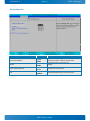
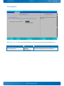
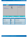
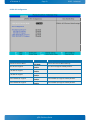
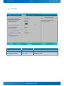
System Information
Phoenix SecureCore Technology Setup
Main
System Information
BIOS Version
Build Time
Processor Type
Processor Speed
System Memory Speed
L2 Cache RAM
Total Memory
F1
Esc
Help
Exit
↑↓
←→
pITXE38.334.TXE1060.PVLV1019.B21 X64
10/30/2014
Intel ® Atom ™ CPU E3845 @ 1.91GHz
1.926 GHz
1333 MHz
2048 KB
4096 MB
Select Item
Select Menu
+/Enter
Change Values
Select ►Sub-Menu
pITX-E38 Users Guide
F9
F10
Setup Defaults
Save and Exit
KTD-N0904-E
Page 37
BIOS - Main
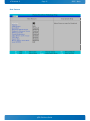
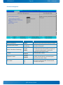
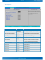
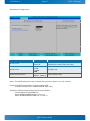
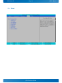
Boot Features
Phoenix SecureCore Technology Setup
Main
Boot Features
NumLock:
Timeout
CSM Support
Quick Boot
Diagnostic Splash Screen
Diagnostic Summary Screen
BIOS Level USB
Console Redirection
Allow Hotkey in S4 resume
UEFI Boot
Legacy Boot
Boot in Legacy Video Mode
Load OPROM
F1
Esc
Help
Exit
↑↓
←→
Item Specific Help
[On]
[ 0]
[Yes]
[Disabled]
[Disabled]
[Disabled]
[Enabled]
[Disabled]
[Enabled]
[Enabled]
[Enabled]
[Disabled]
[All]
Select Item
Select Menu
Select Power-on state for NumLock.
+/Enter
Change Values
Select ►Sub-Menu
pITX-E38 Users Guide
F9
F10
Setup Defaults
Save and Exit
KTD-N0904-E
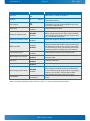
Function
NumLock:
Page 38
Selection
On
Off
BIOS - Main
Description
Select Power-on state for NumLock.
0
CSM Support
No
Yes
Quick Boot
Disabled
Enabled
Enable/Disable quick boot.
Diagnostic Splash Screen
Disabled
Enabled
If you select ‘Enabled’ the diagnostic splash screen
always displays during boot. If you select ‘Disabled’
the diagnostic splash screen does not display unless
you press HOTKEY during boot.
Diagnostic Summary Screen
Disabled
Enabled
Display the diagnostic summary screen during boot.
Disabled
Enabled
Enable/Disable all BIOS support for USB in order to
reduce boot time. Note that this will prevent using a
USB biometric scanner such as a finger print reader
to control access to setup, but does not prevent the
operating system from supporting such hardware.
BIOS Level USB
Console Redirection
Allow Hotkey in S4 resume
UEFI Boot
Legacy Boot
Note 1
Number of seconds that P.O.S.T will wait for the user
input before booting.
Compatibility Support Module that provides backward
compatibility services for legacy BIOS services, like
int10/int13, dependent OS.
Timeout
Disabled
Enabled
Disabled
Enabled
Disabled
Enabled
Disabled
Enabled
Enable/Disable Universal Console Redirection.
Enable hotkey detection when system resuming from
Hibernate state.
Enable the UEFI boot.
Enable the Legacy boot.
Boot in Legacy Video Mode
Disabled
Enabled
Load OPROM
All
On Demand
Enable to force the display adapter to switch the
video mode to Text Mode 3 at the end of BIOS POST
for non-UEFI boot mode (Legacy Boot). Some legacy
software, such as DUET, requires that the BIOS
explicitly enter text video mode prior to boot.
Load all OPROMs or on demand according to the boot
device.
Note 1: Use either digit keys to enter value (0 – 99) or +/- keys to increase/decrease value.
pITX-E38 Users Guide
KTD-N0904-E
Page 39
BIOS - Main
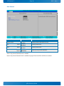
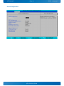
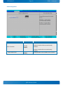
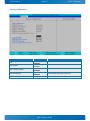
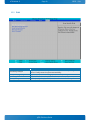
Boot Features
Phoenix SecureCore Technology Setup
Main
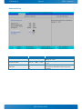
Network Stack
Network Stack
IPv4
IPv6
UEFI PXE Boot Priority
F1
Esc
Help
Exit
↑↓
←→
Function
Network Stack
IPv4
Note1
IPV6
Note1
UEFI PXE Boot Priority
Note2
Item Specific Help
[Enabled]
[Enabled]
[Enabled]
[IPv4 First]
Select Item
Select Menu
Enable/Disable UEFI Network Stack.
+/Enter
Selection
Disabled
Enabled
Disabled
Enabled
Disabled
Enabled
IPV6 First
IPv4 First
Change Values
Select ►Sub-Menu
F9
F10
Setup Defaults
Save and Exit
Description
Enable/Disable UEFI Network Stack.
Enable/Disable IPv4.
Enable/Disable IPv6.
Set the priority of UEFI PXE Boot.
Note1: Only shown if Network Stack is enabled.
Note2: Only shown if Network Stack is enabled and greyed if not both IPv4 and IPV6 are enabled.
pITX-E38 Users Guide
KTD-N0904-E
Page 40
BIOS - Advanced
10.2 Advanced
Main
Phoenix SecureCore Technology Setup
Security
Boot
Exit
Advanced
Item Specific Help
Setup Warning:
Setting items on this screen to incorrect
Values may cause the system to malfunction!
Select Language
► CPU Configuration
► Uncore Configuration
► LAN Configuration
► Hardware Monitor
► Display Configuration
► South Cluster Configuration
► Security Configuration
► Thermal
[English]
OS Selection
F1
Esc
Help
Exit
Select Language.
[Windows]
↑↓
←→
Select Item
Select Menu
+/Enter
Change Values
Select ►Sub-Menu
F9
F10
Setup Defaults
Save and Exit
The Advanced (main) menu contains only submenu selections which will be described in more details on
the following pages.
In order to make a selection of a submenu activated the ↑↓ keys until the requested submenu becomes
white color, then activate the <Enter>.
Function
Select Language
OS Selection
Selection
English
Francais
Etc.
Windows
Linux
Description
Select Language.
OS Selection
Note: OS Selection must be set in according to the requested OS to boot. If incorrect OS Selection then
system will not boot correctly.
pITX-E38 Users Guide
KTD-N0904-E
Page 41
BIOS - Advanced
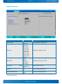
CPU Configuration
Phoenix SecureCore Technology Setup
Advanced
CPU Configuration
CPU Configuration
Execute Disable Bit
AESNI
Limit CPUID Maximum
DTS
Item Specific Help
Execute Disable Bit prevent certain
classes of mailicious buffer overflow
attacks when combined with a
supporting OS.
[Enable]
[Enable]
[Disable]
[Enable]
► CPU Power Management
F1
Esc
Help
Exit
↑↓
←→
Select Item
Select Menu
+/Enter
Function
Selection
Execute Disable Bit
Disable
Enable
AESNI
Limit CPUID Maximum
DTS
Disable
Enable
Disable
Enable
Disabled
Enabled
Change Values
Select ►Sub-Menu
F9
F10
Setup Defaults
Save and Exit
Description
Execute Disable Bit prevent certain classes of
mailicious buffer overflow attacks when
combined with a supporting OS.
AESNI.
Disabled for Windows XP.
Enabled/Disable Digital Thermal Sensor.
pITX-E38 Users Guide
KTD-N0904-E
Page 42
BIOS - Advanced
CPU Power Management
Phoenix SecureCore Technology Setup
Advanced
CPU Power Management
System Power Options
Intel ® SpeedStep ™
Boot performance mode
Intel ® Turbo Boost Technology
C-States
Enhanced C-states
Max C State
F1
Esc
Help
Exit
↑↓
←→
[Enable]
[Max Performance]
[Enable]
[Enable]
[Enable]
[C7]
Select Item
Select Menu
Function
Intel ® SpeedStep ™
Boot performance mode
Item Specific Help
+/Enter
Enable processor performance states
(P-States).
Change Values
Select ►Sub-Menu
Selection
Disable
Enable
Max Performance
Max Battery
F9
F10
Setup Defaults
Save and Exit
Description
Enable processor performance states (P-States).
Select the performance state that the BIOS will
set before OS handoff.
Enable to automatically allow processor cores to
run faster then the base operating frequency if
it´s operating below power, current, and
temperature specification limits.
Intel ® Turbo Boost Technology
Disable
Enable
C-States
Disabled
Enabled
Enable/Disable C States.
Enhanced C-states
Disabled
Enabled
Enable/Disable C1E, C2E and C4E. When
enabled, CPU will switch to minimum speed
when all cores enter C-State.
Max C State
C7
C6
C4
C1
This option controls the Max C State that the
processor will support.
pITX-E38 Users Guide
KTD-N0904-E
Page 43
BIOS - Advanced
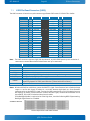
Uncore Configuration
Phoenix SecureCore Technology Setup
Advanced
Uncore Configuration
GOP Configuration
GOP Driver
[Enable]
IGD Configuration
Integrated Graphics Driver
Primary Display
PAVC
DVMT Pre-Allocated
Spread Spectrum clock
[Enable]
[Auto]
[LITE Mode]
[64M]
[Disable]
IGD – LCD Control
LCD Panel Type
IGD Boot Type
Panel Scaling
[Auto]
[Auto]
[Auto]
F1
Esc
Help
Exit
↑↓
←→
Select Item
Select Menu
+/Enter
Item Specific Help
Enable GOP Driver will unload
VBIOS; Disable it will load VBOIS.
Change Values
Select ►Sub-Menu
pITX-E38 Users Guide
F9
F10
Setup Defaults
Save and Exit
KTD-N0904-E
Function
GOP Driver
Integrated Graphics Driver
Primary Display
PAVC
DVMT Pre-Allocated
Spread Spectrum clock
LCD Panel Type
Page 44
Selection
Disabled
Enabled
Disabled
Enabled
AUTO
IGD
PCIe
SG
Disable
LITE Mode
SERPENT Mode
64M, 96M, …, 512M
Disabled
Enable
Auto
Panel1 640 x 480
Panel2 800 x 600
Panel3 1024 x 768
Panel4 1280 x 1024
Panel5 1400 x 1050
Panel6 1400 x 1050
Panel7 1600 x 1200
Panel8 1360 x 768
Panel9 1680 x 1050
Panel10 1820 x 1200
Panel11 1440 x 900
Panel12 1280 x 1024
Panel13 1600 x 900
Panel14 1024 x768
Panel15 1920 x 1080
Panel16 2048 x 1536
BIOS - Advanced
Description
Enable GOP Driver will unload VBIOS; Disable
it will load VBOIS.
Enable: Enable Integrated Graphics Device
(IGD) when selected as the Primary Video
Adaptor.Disable: Always disabled IGD.
Select which of IGD/PCI Graphics device
should be Primary Display Or select SG for
Switchable/Hybrid Gfx.
Enable/Disable Protected Audio Video
Control.
Select DVMT 5.0 Pre-Allocated (Fixed)
Graphics Memory size used by the Internal
Graphics Device.
Enable clock chip Spread Spectrum feature.
IGD Boot Type
Auto
VGA Port
HDMI Port B
DP Port B
DP Port C
eDP
DSI Port A
DSI Port C
Selects preference for Integrated Graphics
Device (IGD) display interface used when
system boots. If CSM Enable:
HDMI PortB=EFP1
DP PortB=EFP1
DP PortC=EFP2
eDP=LFP1
DSI PortA=LFP2
DSI PortC=LFP2
Panel Scaling
Auto
Centering
Stretching
Select the LCD panel scaling option used by
Internal Graphics Device.
pITX-E38 Users Guide
KTD-N0904-E
Page 45
BIOS - Advanced
LAN Configuration
Phoenix SecureCore Technology Setup
Advanced
LAN Configuration
Item Specific Help
LAN Configuration
System UUID {A7409B5D-A70F-1350-3D4D-6ADB329A768B}
ETH1 Configuration
MAC Address & Link status :
F1
Esc
Help
Exit
↑↓
←→
Control the Ethernet Devices and
PXE boot.
[Enabled]
[00E0F42CF929-]
Select Item
Select Menu
+/Enter
Change Values
Select ►Sub-Menu
F9
F10
Setup Defaults
Save and Exit
Note: The “+” and “-“(to the right of the MAC address) indicates respectively if link is established or not.
Function
ETH1 Configuration
Selection
Disabled
Enabled
With PXE boot
Description
Control the Ethernet Devices and PXE boot.
pITX-E38 Users Guide
KTD-N0904-E
Page 46
BIOS - Advanced
Hardware Monitor
Phoenix SecureCore Technology Setup
Advanced
Hardware Monitor
Item Specific Help
Hardware Monitor
Board Temp
CPU Control Temp
Internal CPU Temp
Fan Speed
[ºC]:
[ºC]:
[ºC]:
[RPM]:
Fan Trip Point
Trip Point Speed
Fan Poles
F1
Esc
Help
Exit
Temperature where fan accelerates.
Range 20 – 80 C.
[32]
[33]
[24]
[4810]
[ºC]: [30]
[ % ]: [ 50]
: [4]
↑↓
←→
Select Item
Select Menu
+/Enter
Change Values
Select ►Sub-Menu
Function
Selection
Fan Trip Point
20, 21, …, 30, …, 80
Trip Point Speed
30, 31, …, 50, …, 100
Fan Poles
2
4
6
F9
F10
Setup Defaults
Save and Exit
Description
Temperature where fan accelerates.
Range 20 – 80 C.
Fan speed at trip point in %. Minimum value
is 30.
The number of pole pairs inside the fan. Ex:
Fan poles=4 generates 2 pulses every one
rotation.
pITX-E38 Users Guide
KTD-N0904-E
Page 47
BIOS - Advanced
Display Configuration
Advanced
Phoenix SecureCore Technology Setup
Display Configuration
Item Specific Help
Display Configuration
Onboard LVDS
Resolution
Manufacture
Panel name
Panel VCC
Backlight Enable Active
F1
Esc
Help
Exit
↑↓
←→
Enable/Disable onboard LVDS.
[Enabled]
[640 x 480]
[(Standard)]
[640x480 18]
[3,3V]
[Low]
Select Item
Select Menu
+/Enter
Change Values
Select ►Sub-Menu
Function
F9
F10
Setup Defaults
Save and Exit
Selection
Description
Disabled
Onboard LVDS
Enable/Disable onboard LVDS.
Enabled
640 x 480
800 x 480
800 x 600
1024 x 600
1024 x 768
Resolution
Resolution of panel to select.
1280 x 800
1280 x 1024
1366 x 768
1600 x 1200
1920 x 1080
Custom
(Standard)
AUO
Manufacture
Manufacture of panel to select.
Philips
Primeview
Samsung
640x480 18
Panel name
Note1 640x480 24
Name of panel to select.
N/A
3,3V
Panel VCC
VCC of panel selected panel.
5V
Low
Backlight Enable Active
Inversion of backlight signal.
High
Note1: Depend on Resolution and Manufacture combination. If combination does’nt exist then Panel name
is N/A (Not Available).
pITX-E38 Users Guide
KTD-N0904-E
Page 48
BIOS - Advanced
South Cluster Configuration
Phoenix SecureCore Technology Setup
Advanced
South Cluster Configuration
Item Specific Help
► PCI Express Configuration
► USB Configuration
► Audio Configuration
► SATA Drives
► LPSS & SCC Configuration
► Miscellaneous Configuration
F1
Esc
Help
Exit
↑↓
←→
PCI Express Configuration Settings.
Select Item
Select Menu
+/Enter
Change Values
Select ►Sub-Menu
pITX-E38 Users Guide
F9
F10
Setup Defaults
Save and Exit
KTD-N0904-E
Page 49
BIOS - Advanced
PCI Express Configuration
Advanced
Phoenix SecureCore Technology Setup
PCI Express Configuration
PCIe 1 Speed
PCIe 2 Speed
PCI Express Root Port 2
PCI Express Root Port 3
F1
Esc
Help
Exit
Function
PCIe 1 Speed
PCIe 2 Speed
PCI Express Root Port 2
PCI Express Root Port 2
↑↓
←→
Item Specific Help
[Auto]
[Auto]
[Enable]
[Enable]
Select Item
Select Menu
+/Enter
Selection
Auto
Gen1
Gen2
Auto
Gen1
Gen2
Enable
Disable
Enable
Disable
Configure PCIe Speed.
Change Values
Select ►Sub-Menu
F9
F10
Setup Defaults
Save and Exit
Description
Configure PCIe Speed.
Configure PCIe Speed.
Control the PCI Express Root Port.
Control the PCI Express Root Port.
pITX-E38 Users Guide
KTD-N0904-E
Page 50
BIOS - Advanced
USB Configuration
Phoenix SecureCore Technology Setup
Advanced
USB Configuration
Item Specific Help
xHCI Mode
XHCI Link Power Management
[Disable]
[Enable]
USB OTG Support
[Disable]
EHCI Controller
USB Per-Port Control
USB Port #0
USB Port #1
USB Port #2
USB Port #3
[Enable]
[Enable]
[Enable]
[Enable]
[Enable]
[Enable]
F1
Esc
Help
Exit
↑↓
←→
Select Item
Select Menu
+/Enter
Function
Selection
xHCI Mode
Disable
Smart Auto
XHCI Link Power Management
USB OTG Support
Disable
Enable
Disable
PCI Mode
ACPI Mode
Mode of operation of xHCI controller.
To use DOS, enable EHCI and
disable XHCI.
Change Values
Select ►Sub-Menu
F9
F10
Setup Defaults
Save and Exit
Description
Mode of operation of xHCI controller.
To use DOS, enable EHCI and disable XHCI.
Enable/Disable XHCI Link Power Management.
Enable/Disable USB OTG Support
Control the USB EHCI (USB 2.0) functions.
EHCI Controller
Enable
Disable
One EHCI controller must always be enabled.
To use DOS, enable EHCI and disable XHCI.
USB Per-Port Control
USB Port #0
USB Port #1
USB Port #2
USB Port #3
Disable
Enable
Disable
Enable
Disable
Enable
Disable
Enable
Disable
Enable
Control each of the USB ports (0~3) disabling.
Disable USB port.
Disable USB port.
Disable USB port.
Disable USB port.
pITX-E38 Users Guide
KTD-N0904-E
Page 51
BIOS - Advanced
Audio Configuration
Advanced
Phoenix SecureCore Technology Setup
Audio Configuration
Audio Controller
Azalia HDMI Codec
Item Specific Help
[Enable]
[Enable]
Control Detection of the Azalia
device.
Disabled = Azalia will be
unconditionally disabled.
Enabled = Azalia will be
unconditionally Enabled.
F1
Esc
Help
Exit
↑↓
←→
Select Item
Select Menu
+/Enter
Function
Selection
Audio Controller
Disable
Enable
Change Values
Select ►Sub-Menu
F9
F10
Setup Defaults
Save and Exit
Description
Control Detection of the Azalia device.
Disabled = Azalia will be unconditionally
disabled.
Enabled = Azalia will be unconditionally
Enabled.
Azalia HDMI Codec
Disable
Enable
Enable/Disable internal HDMI codec for Azalia.
pITX-E38 Users Guide
KTD-N0904-E
Page 52
BIOS - Advanced
SATA Drives
Phoenix SecureCore Technology Setup
Advanced
SATA Drives
Item Specific Help
SATA Drives
Chipset-SATA Controller Configuration
Chipset SATA
Chipset SATA Mode
SATA Port 0 Hot Plug Capability
SATA Port 1 Hot Plug Capability
F1
Esc
Help
Exit
↑↓
←→
Select Item
Select Menu
[Enabled]
[ACHI]
[Disabled]
[Disabled]
+/Enter
Function
Selection
Chipset SATA
Disabled
Enabled
Chipset SATA Mode
IDE
AHCI
SATA Port 0 Hot Plug Capability
SATA Port 1 Hot Plug Capability
Enables or Disables the Chipset
SATA Controller. The Chipset SATA
Controller supports the internal
SATA ports (up to 3Gb/s supported
per port).
Disabled
Enabled
Disabled
Enabled
Change Values
Select ►Sub-Menu
F9
F10
Setup Defaults
Save and Exit
Description
Enables or Disables the Chipset SATA Controller.
The Chipset SATA Controller supports the
internal SATA ports (up to 3Gb/s supported per
port).
IDE: Compatibility mode disables AHCI support.
AHCI: Supports advanced SATA features such as
Native Command Queuing.
Warning: OS may not boot if this setting is
changed after OS install.
If enabled, SATA port will be reported as Hot
Plug capable. Note: Requires hardware support.
If enabled, SATA port will be reported as Hot
Plug capable. Note: Requires hardware support.
pITX-E38 Users Guide
KTD-N0904-E
Page 53
BIOS - Advanced
LPSS & SCC Configuration
Phoenix SecureCore Technology Setup
Advanced
LPSS & SCC Configuration
LPSS & SCC Devices Mode
Item Specific Help
[PCI Mode]
LPSS & SCC Devices Mode Settings.
SCC Configuration
SCC SD Card Support
SD SDR 25 Support
SD SDR 50 Support
LPSS HSUART #1 Support
LPSS HSUART #2 Support
F1
Esc
Help
Exit
↑↓
←→
Function
LPSS & SCC Device Mode
SCC SD Card Support
SD SDR 25 Support
SD SDR 50 Support
LPSS HSUART #1 Support
LPSS HSUART #2 Support
[Enable]
[Enable]
[Enable]
[Enable]
[Enable]
Select Item
Select Menu
+/Enter
Selection
ACPI Mode
PCI Mode
Disable
Enable
Disable
Enable
Disable
Enable
Disable
Enable
Disable
Enable
Change Values
Select ►Sub-Menu
F9
F10
Setup Defaults
Save and Exit
Description
LPSS & SCC Devices Mode Settings.
SCC SD Card Support Enable\Disable.
LPSS HSUART #1 Support Enable\Disable.
LPSS HSUART #2 Support Enable\Disable.
pITX-E38 Users Guide
KTD-N0904-E
Page 54
BIOS - Advanced
Miscellaneous Configuration
Phoenix SecureCore Technology Setup
Advanced
Miscellaneous Configuration
Miscellaneous Configuration
AC Power Loss
PCI Mmio Size
mSATA/mPCIE Selection
F1
Esc
Help
Exit
↑↓
←→
Function
AC Power Loss
PCI Mmio Size
mSATA/mPCIE Selection
Item Specific Help
Specify what state to go to when
power is re-applied after a power
failure (G3 state).
[Power On]
[1GB]
[mPCIE]
Select Item
Select Menu
+/Enter
Change Values
Select ►Sub-Menu
Selection
Power On
Power Off
2GB
1.5GB
1.25GB
1GB
mPCIE
mSATA (Note 1)
F9
F10
Setup Defaults
Save and Exit
Description
Specify what state to go to when power is reapplied after a power failure (G3 state).
PCI Mmio Size.
Select mSATA or PCIE.
Note 1: The mSATA setting works only on released board versions. (Batch no. 01.00 or above).
Example of mSATA modules working with the setting mPCIE:
SanDisk X110 mSATA SSD - 128GB (SD6SF1M-128G-1022)
Examples of mSATA modules working with the setting mSATA:
Transcend MSA370 (TS64GMSA370)
Apacer APSDM016GM5PN-PCM (0 °C to 70 °C)
Apacer APSDM016GM5PN-PCMW (-40 °C to 85 °C)
pITX-E38 Users Guide
KTD-N0904-E
Page 55
BIOS - Advanced
Security Configuration
Phoenix SecureCore Technology Setup
Advanced
Security Configuration
TXE Configuration
TXE FW Version
TXE FW Capabilities
TXE FW Features
TXE FW OEM Tag
TXE Firmware Mode
TXE File System Integrity Value
TXE
TXE HMRFPO
TXE Firmware Update
TXE EOP Message
TXE Unconfiguration Perform
F1
Esc
Help
Exit
↑↓
←→
Function
TXE
TXE HMRFPO
TXE Firmware Update
TXE EOP Message
Item Specific Help
1.0.2.1060
A0001040
A0001040
00000000
Normal
0
[Enable]
[Disable]
[Enable]
[Enable]
Select Item
Select Menu
+/Enter
Selection
Disabled
Enabled
Disabled
Enabled
Disabled
Enabled
Disabled
Enabled
Change Values
Select ►Sub-Menu
F9
F10
Setup Defaults
Save and Exit
Description
Send EOP Message Before Enter OS
TXE Unconfiguration Perform
pITX-E38 Users Guide
KTD-N0904-E
Page 56
BIOS - Advanced
Thermal
Phoenix SecureCore Technology Setup
Advanced
Thermal
Item Specific Help
Thermal Configuration Parameters
Critical Trip Point
Passive Trip Point
This value controls the temperature
of the ACPI Critical Trip Point – the
point in which the OS will shut the
system off.
[90 C]
[85 C]
Dynamic Platform & Thermal Framework
DPFT
CPU Sensor Participants
Critical
Passive
Ambient Sensor Participants
Critical
Passive
DDR Sensor Participants
Critical
Passive
[Disable]
NOTE: 100C is the Plan Of Record
(POR) for all Intel mobile processors.
[70 C]
[60 C]
[70 C]
[52 C]
[85 C]
[61 C]
Start P-State
Step Size
Power Control Setting
Performance Control Setting
[P0]
[25%]
[Core Offlining]
[Core Offlining]
Charger Participant
Display Participant
Power Participant
[Enable]
[Enable]
[Enable]
F1
Esc
Help
Exit
↑↓
←→
Select Item
Select Menu
+/Enter
Change Values
Select ►Sub-Menu
Function
Selection
Critical Trip Point
15 C, 23C, 31 C,
39C, 47 C, 55 C, 63
C, 71 C, 79 C, 85 C,
87 C, 90 C
Passive Trip Point
DPFT
Charger Participant
Display Participant
Power Participant
15 C, 23C, 31 C,
39C, 47 C, 55 C, 63
C, 71 C, 79 C, 85 C,
87 C, 90 C
Disable
Enable
Disable
Enable
Disable
Enable
Disable
Enable
F9
F10
Setup Defaults
Save and Exit
Description
This value controls the temperature of the ACPI
Critical Trip Point – the point in which the OS will
shut the system off.
NOTE: 100C is the Plan Of Record (POR) for all
Intel mobile processors.
This value controls the temperature of the ACPI
Passive Trip Point – the point in which the OS
will begin to throttling the processor.
Enable/Disable DPTF.
Enable/Disable Charger Participant Device.
Enable/Disable Display Participant Device.
Enable/Disable Power Participant Device.
pITX-E38 Users Guide
KTD-N0904-E
Page 57
BIOS - Security
10.3 Security
Main
Advanced
Secure Boot Activation
► Secure Boot Configuration
Supervisor Password is:
User Password is:
Phoenix SecureCore Technology Setup
Security
Boot
Exit
Item Specific Help
[Disabled]
Set or clear the Supervisor
account’s password.
Cleared
Cleared
Set Supervisor Password
Supervisor Hint String
[Enter]
[
]
Set User Password
User Hint String
[Enter]
[
]
Min. password length
[ 1]
Authenticate User on Boot
[Disabled]
HDD Security Status
No HDD detected
F1
Esc
Help
Exit
↑↓
←→
Select Item
Select Menu
+/Enter
Function
Set Supervisor Password
Supervisor Hint String
Selection
(up to 20 characters)
(up to 20 characters)
Min. password length
1, 2, …, 20
Change Values
Select ►Sub-Menu
F9
F10
Setup Defaults
Save and Exit
Description
Set or clear the Supervisor account’s password.
Press Enter to type Supervisor Hint String.
Set the minimum number of characters for
password (1-20).
pITX-E38 Users Guide
KTD-N0904-E
Page 58
BIOS - Boot
10.4 Boot
Main
Advanced
Phoenix SecureCore Technology Setup
Security
Boot
Exit
Item Specific Help
Boot Priority Order
1. ATAPI CD:
2. PCI LAN:
3. ATA HDD0:
4. ATA HDD1:
5. USB HDD:
6. USB CD:
7. USB FDD:
8. SD Card1:
9. Internal Shell:
F1
Esc
Help
Exit
↑↓
←→
Keys used to view or configure
devices: ↑ and ↓ arrows Select a
device. ‘+’ and ‘-‘ move the device
up or down. ‘Shift + 1’ enables or
disables a device. ‘Del’ deletes an
unprotected device.
Select Item
Select Menu
+/Enter
Change Values
Select ►Sub-Menu
pITX-E38 Users Guide
F9
F10
Setup Defaults
Save and Exit
KTD-N0904-E
Page 59
BIOS - Exit
10.5 Exit
Main
Advanced
Phoenix SecureCore Technology Setup
Security
Boot
Exit
Item Specific Help
Exit Saving Changes
Exit Discarding Changes
Load Setup Defaults
Discard Changes
Save Changes
F1
Esc
Help
Exit
↑↓
←→
Function
Exit Saving Changes
Exit Discarding Changes
Load Setup Defaults
Discard Changes
Save Changes
Equal to F10, save all changes of
all menus, then exit setup
configure driver. Finally resets
the system automatically.
Select Item
Select Menu
+/Enter
Change Values
Select ►Sub-Menu
F9
F10
Setup Defaults
Save and Exit
Description
Equal to F10, save all changes of all menus, then exit setup configure
driver. Finally resets the system automatically.
Equal to ESC, never save changes, then exit setup configure driver.
Equal to F9. Load standard defaults values.
Load the original value of this boot time. Not the default Setup value.
Save all changes of all menus, but do not reset system.
pITX-E38 Users Guide