1
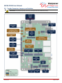
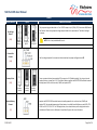
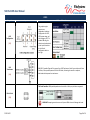
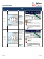
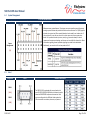
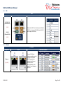
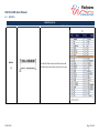
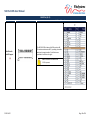
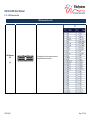
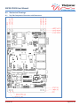
SBC35-CC405 User Manual WinSystems, Inc. 715 Stadium Drive Arlington, TX 76011 (817) 274-7553 www.winsystems.com SBC35-CC405 User Manual Revision History Revision Date Code ECO Number 2014-06-20 Initial Release SBC35-CC405 User Manual Table of Contents Introduction.............................................................................................................................................................. 1 Specifications............................................................................................................................................................ 1 1.0 Before You Begin ............................................................................................................................................. 2 2.0 Locating Connectors, Switches, and Jumpers .................................................................................................... 2 3.0 Topside Connectors, Jumpers, and Switches ..................................................................................................... 3 3.1 Edge Connectors, Ports, and Inputs .......................................................................................................................... 4 4.0 Connector, Switch, and Jumper Configurations ................................................................................................. 5 4.1 Power ........................................................................................................................................................................ 5 4.2 Video ......................................................................................................................................................................... 7 4.3 Audio ....................................................................................................................................................................... 10 4.4 System Management .............................................................................................................................................. 11 4.5 Serial........................................................................................................................................................................ 11 4.6 USB .......................................................................................................................................................................... 12 4.7 Ethernet .................................................................................................................................................................. 12 4.8 Serial ATA (SATA) .................................................................................................................................................... 14 4.9 MINIPCIe ................................................................................................................................................................. 15 4.10 IO60 Expansion Bus ................................................................................................................................................. 17 5.0 Setup ................................................................................................................................................................ 18 5.1 Installation/Hookup ................................................................................................................................................ 18 5.2 Power Up................................................................................................................................................................. 18 6.0 BIOS Settings ................................................................................................................................................. 19 6.1 Boot Up and the Main Menu .................................................................................................................................. 19 6.2 Advanced Menu ...................................................................................................................................................... 21 6.3 Others Menu ........................................................................................................................................................... 25 6.4 Security Menu ......................................................................................................................................................... 28 6.5 Boot Menu .............................................................................................................................................................. 29 6.6 Exit Menu ................................................................................................................................................................ 30 7.0 Cables and Software Drivers ........................................................................................................................... 31 8.0 Mechanical Drawings ..................................................................................................................................... 32 8.1 Top Side Component Illustration with Dimensions ................................................................................................ 32 8.2 Edge View Component Illustration ......................................................................................................................... 33 Appendix A – Best Practices .................................................................................................................................... 34 A.1 Power Supply................................................................................................................................................. 34 A.2 Power Down .................................................................................................................................................. 34 A.3 Mounting and Protecting the Single Board Computer...................................................................................... 35 A.4 Conformal Coating ......................................................................................................................................... 35 A.5 Operations/Product Manuals ......................................................................................................................... 35 Warranty Information ............................................................................................................................................. 36 2014-06-20 Page i SBC35-CC405 User Manual Introduction The SBC35-CC405 is a high-performance, industrial, small form factor (SFF) Single Board Computer (SBC) capable of operating at very high temperatures without a fan or heat-pipe. The processor for the unit is an Intel E3800 series Atom, integrated into the SBC35-CC405 using a Type 6 COM Express module. The low-profile thermal solution provides a rugged platform base that protects the PCB assembly and offers convenient four-point mounting. Information to configure and operate the SBC35-CC405 for most applications is included in this User Manual or on our website at www.winsystems.com. If additional information is required, call WinSystems Technical Support at (817) 274-7553 and speak with one of our Application Engineers; they are available M-F, 8 AM to 5 PM, Central Daylight Time (CDT) for assistance with all of your product requirements. Specifications Feature Processor Core Speed Number of Cores L2 Cache Graphics Graphics Frequency Virtualization Operating Systems Video Interfaces Memory (RAM) BIOS Ethernet Speed Advanced Features Storage (Bootable) Serial I/O Bus Expansion USB Watchdog Timer Audio Audio Interfaces Power 1 Mechanical Weight Operating Temperature Range Storage Temperature 1 SBC35-CC405-3815 Intel® Atom™ E3815 1.46 GHz 1 512 KB SBC35-CC405-3827 SBC35-CC405-3845 Intel® Atom™ E3827 Intel® Atom™ E3845 1.75 GHz 1.91 GHz 2 4 1 MB 2 MB Intel® Gen 7 Graphics Engine 400 MHz 542/792 MHz (Turbo) Hardware based Intel® VT-x Linux, Windows, DOS, and other x86 compatible Up to 2 Active Displays VGA up to 2560x1536 at 24bpp Display Port 1.1 LVDS 18 or 24 Bpp 2, 4, or 8 GB DDR3L SDRAM Phoenix 2 Intel® I210 GbE controllers Auto-negotiation for 10/100/1000 Mb/s IEEE1588 and IEEE 802.1AS time stamping IEEE802.Qav Audio-Video Bridging (AVB) Advanced Power Management (APM) Support Remote boot 1 SATA (2.0) channel 1 CFAST socket (on back of the board) 1 mSATA socket (MiniPCIe socket) 2 serial ports (RS-232/422/485) 2x MiniPCIe (One supports mSATA, One supports USB 2.0) 2 IO60 (SPI, I C, PWM) 1 USB 3.0 port, 3 USB 2.0 ports, and 1 USB interface @ J14 Adjustable from 1 second to 255 minute reset HD Audio supported Display Port 1.1 Line Out, Line In, Mic to 3.5 mm 7.1 Surround +10 to 50V DC input +10 to 50V DC input +10 to 50V DC input (7W typical/ 9 W Max) (7.5W typical/ 10W Max) (8.75W typical/ 12W Max) Dimensions: 4 x 6.125 x 2.3 inches (102 x 156 x 58 mm) Weight: 1.40 lbs. (635g) with heat sink -40°C to +85°C (-40°F to +185°F) -50°C to +95°C (-58°F to +203°F) Power consumption estimates are for the SBC35-CC405 only and exclude any external devices. 2014-06-20 Page 1 of 36 SBC35-CC405 User Manual Feature Shock Vibration MTBF SBC35-CC405-3815 SBC35-CC405-3827 TBD TBD TBD SBC35-CC405-3845 1.0 Before You Begin This User Manual provides instructions for optimal performance, prevention of injury, and/or damage to the product. You may VOID the warranty and/or cause damage by neglecting to follow the Best Practices as outlined in Appendix - A. 2.0 Locating Connectors, Switches, and Jumpers To locate connectors, switches, and jumpers as described on the following pages, place the SBC35-CC405 (component side up) with the serial ports and Ethernet/USB connectors facing to your right (as depicted below). This ensures your view is consistent with the illustrations provided in the pages that follow, which identify physical locations for each connector, switch, and jumper; they also provide brief descriptions of their function and diagrams of pin/jumper configurations where appropriate. NOTE: To view information on a connector, switch, or jumper, click on its descriptor box; you will jump to a page with more information. To return to the previous location, click on the image or text in the layout section of the table. 2014-06-20 Page 2 of 36 SBC35-CC405 User Manual 3.0 Topside Connectors, Jumpers, and Switches IMPORTANT! This product ships with a heat sink; removing the heat sink VOIDS the warranty. 2014-06-20 Page 3 of 36 SBC35-CC405 User Manual 3.1 Edge Connectors, Ports, and Inputs 2014-06-20 Page 4 of 36 SBC35-CC405 User Manual 4.0 Connector, Switch, and Jumper Configurations 4.1 Power For locations of Connectors, switches, jumpers, and ports, refer to Sections 2 and 3 of this User Manual. POWER Name/Function Power Button [SW1] +10 - +50 Volt DC Power Input [J5] Layout Additional Information The Power Button (SW1), located on the lower right edge of the board next to the audio line in/line out/microphone input, controls power to the SBC35-CC405. Upon initial hookup of power to J5, the power button is bypassed and the board powers up automatically. However, after initial power up: • A brief press of SW1 powers the unit on or off, depending on the present state • If the unit accidentally locks up and is unresponsive, press and hold SW1 for four (4) seconds to perform a hard restart The SBC35-CC405 is capable of operating from +10 to +50 VDC (+/-5%). The green power input connector (J5) is located next to the power button on the edge of the board. WARNING! If you reverse the voltage from what is depicted in the image to the left, you will void the warranty and damage the board. 6 2014-06-20 Page 5 of 36 SBC35-CC405 User Manual POWER Name/Function Layout Additional Information This jumper setting provides either a +5 or +12 VDC output at pin 3 (FAN_VCC) of connector J10, External Fan Connect. Select the appropriate voltage output based on fan requirements. The default setting is no jumper. Fan Voltage Output [JP2] Default Setting For 5VDC @ J10 For 12V DC @ J10 External Fan Connect NOTE: A fan is not provided with the unit. The fan voltage output of this connector is determined by the jumper configuration on JP2. [J10] Battery Select [JP3] External Battery Connect [J7] No battery backup External battery backup Internal battery backup To use an external battery (connected at J7), jumper pins 1 & 2 (default setting). For using an internal (optional) battery, jumper pins 2 & 3. The external battery supplies the SBC35-CC405 board with external standby power for the real-time clock, CMOS, and optional GPS. Supplies the SBC35-CC405 board with external standby power for the real-time clock, CMOS, and optional GPS. An extended temperature lithium battery is available from WinSystems, part # BAT-LTC-E36-16-1 or BAT-LTC-E-36-27-1. For OEM applications, an on-board battery can be integrated into the motherboard. Please contact a WinSystems’ Application Engineer for more information. 6 2014-06-20 Page 6 of 36 SBC35-CC405 User Manual 4.2 Video VIDEO Designation Display Port 1.1 [J15] Analog VGA [J21] LVDS & Backlight [J12] Layout Additional Information The Display Port 1.1 connector is located at J15. Aside from video, it also delivers high definition (HD) audio. See the Audio section for more information. SBC35-CC405 supports analog VGA and requires cable (CBL-234-G-1-1.375C) from WinSystems. Flat panel displays connect to the SBC35-CC405 motherboard at J12. The board supports LVDS resolutions up to 1920x1200 at 24 bits per pixel (Bpp). A USB Touchscreen interface connection is located at J14. Panel color mode selection for 6-or 8-bits per pixel is configured at JP4. All resolutions are panel hardware dependent. 6 2014-06-20 Page 7 of 36 SBC35-CC405 User Manual VIDEO Designation LVDS Configuration [JP5] USB Touchscreen [J14] Layout Additional Information The graphics engine supports two independent interfaces. Configuration for LVDS, LVDS output swing, and 2 clock frequency for I C is made at JP5 using the selection options depicted in the layout illustration to the left and configuration table to the right. J14 (USB 5) provides Plug-and-Play support for a USB Touchscreen. Aside from a simpler and faster interface, it also provides power within the USB cable, eliminating the need for a separate, dedicated cable to power the touchscreen. Flat Panel Controller. JP4 is panel dependent and controls 6 or 8-bits per pixel where supported. Bits Per Pixel [JP4] WARNING! Jumpering more than one set of pins on JP4 at a time will damage the board. 6 2014-06-20 Page 8 of 36 SBC35-CC405 User Manual VIDEO Designation Backlight Power [JP7] Panel Orientation [JP6] Layout Additional Information Use the layout graphic on the left and/or the configuration table on the right to select the appropriate jumper for backlight power and backlight enable at JP7. The jumpers on JP6 control up/down and left/right panel orientation. Use the layout graphic on the left and/or panel orientation table on the right to determine the appropriate jumpers. * Not all panels support left/right orientation. WARNING! JP7 supports one jumper for backlight enable settings and one jumper for backlight power settings (two total). However, jumpering more than one set of pins (for backlight enable) and one set of pins (for backlight power) will damage the board. WARNING! JP6 supports one jumper for horizontal panel orientation and one jumper for vertical panel orientation (two total). However, jumpering more than one set of pins (for vertical) and one set of pins (for horizontal) will damage the board. 6 2014-06-20 Page 9 of 36 SBC35-CC405 User Manual 4.3 Audio The SBC35-CC405 Intel Atom E3800 family processor uses the Realtek ALC888S-VD codec controller which provides both Digital and Analog channels. The controller has three jack detection pins and a built-in beep generator. The SBC35-CC405 supports three audio interfaces - one digital (Display Port 1.1), two analog (Stereo Audio [Line-In/LineOut/Microphone], and one HD Audio (7.1 Surround). The Display Port 1.1 interface located at J15 also delivers video capability; see more information about this interface in the Video section of this user manual. AUDIO Designation Stereo Audio (Line-In, Line-Out, & Mic Layout Additional Information The SBC35-CC405 uses 3.5-mm stereo line-out, line-in, and microphone jacks at J6. The diagram to the left depicts the line-in, line-out, and microphone ports. [J6] HD Audio 7.1 Surround [J2] HD Audio connection. WinSystems cable CBL-AUDIO7102-12, delivers 7.1 (surround sound) audio from this connector. CBL-AUDIO5-102-12 delivers 5.1 audio, and CBL-AUDIO3-102-12 delivers stereo audio. 6 2014-06-20 Page 10 of 36 SBC35-CC405 User Manual 4.4 System Management SYSTEM MANAGEMENT Designation Layout Additional Information J4 supports many system features. The primary uses are to provide a security feature to manage system intrusion and provide notification on thermal status. Pin 2 (LID#) signifies whether the system is on/off or opened/closed and can be used for an intruder alert. If this particular bit is set, the user can wire it to their system to initiate a system shut down. Pin 4 provides thermal trip status, action (e.g., system shut down) is taken in response to the system overheating, and the user can be notified of a thermal trip. More information regarding thermal protection signaling is provided in the table below. Additionally, you can also tie J4 to a sleep mode via Pin 3. System Management [J4] 4.5 Serial Designation COM 1 [J19A] COM 2 [J19B] Layout SERIAL Additional Information The SBC35-CC405 is equipped with two on-board serial ports (RS-232/422/485) at J19. Both serial channels use the advanced EXAR SP339E multiprotocol transceiver. Both ports are configured in the BIOS and include options for 120-ohm receiver termination, slew rate, and protocol. 6 2014-06-20 Page 11 of 36 SBC35-CC405 User Manual 4.6 USB USB Designation Layout Additional Information USB 2.0 / 3.0 (Channels 1 & 3) [J11] J11 provides USB 3.0 on the bottom port (CH3) and USB 2.0 on the top port (CH1). J13 provide USB 2.0 on both ports (CH2 & CH4). USB 2.0 (Channels 2 & 4) [J13] 4.7 Ethernet ETHERNET Designation Ethernet [J11, J13] Layout Additional Information Two Intel I210 Gigabit Ethernet controllers provide standard IEEE 1588 and 802.1AS protocol timestamping. Each Ethernet interface includes 10/100/1000 MP/s multispeed, full, and half-duplex operation. 6 2014-06-20 Page 12 of 36 SBC35-CC405 User Manual ETHERNET Designation Ethernet (GPIO) Controller [J20] Ethernet GPIO Reference Voltage Selection [JP8] Ethernet LEDs Layout Additional Information The SBC35-CC405 is equipped with an Ethernet GPIO connector at J20, which is associated with Ethernet port 2 at J13. Reference power to J20 is controlled by jumper settings on JP8 (below). The table to the right provides jumpers for voltage settings on JP8. The board supports voltages of 3.3V, 5V, and 12V. WARNING! Jumpering more than one set of pins at a time will damage the board. On-board Ethernet activity LEDs are built into the connectors at J11 & J13. There is one green LED (left) and one bi-color green/yellow LED (right). Activity signals for these lights are defined in the table to the right. 6 2014-06-20 Page 13 of 36 SBC35-CC405 User Manual 4.8 Serial ATA (SATA) SERIAL ATA (SATA) Designation Serial ATA [J3] SATA Power [J1] CFAST (SATA SSD) [J103] On back of the board Layout Additional Information The bootable SATA (2.0) interface is located at J3. WinSystems offers CBL-SATA701-20 for this connector. NOTE: J3 cannot be used when J9 mSATA is present. Power is supplied to the SATA device via the connector at J1. WinSystems offers CBL-PWR-117-12 for this connector. The SBC35-CC405 supports CFAST storage at J103 located on the back of the board. CFAST is a small form factor SATA SSD. Pin definitions are provided in the table to the right. 6 2014-06-20 Page 14 of 36 SBC35-CC405 User Manual 4.9 MINIPCIe MINIPCIe (J8, J9) Designation MiniPCIe [J8] Layout Additional Information The SBC35-CC405 includes a MiniPCIe socket at J8. Pin definitions are provided in the table to the right. 6 2014-06-20 Page 15 of 36 SBC35-CC405 User Manual MINIPCIe (J8, J9) Designation MiniPCIe with mSATA Support [J9] Layout Additional Information The SBC35-CC405 includes a MiniPCIe socket at J9. The socket auto detects mSATA, providing a bootable media and storage interface. Pin definitions are provided in the table to the right. NOTE: J9 cannot be used when J3 SATA is present. 6 2014-06-20 Page 16 of 36 SBC35-CC405 User Manual 4.10 IO60 Expansion Bus IO60 Expansion Bus (J16) Designation IO60 Expansion Bus Layout Additional Information The expansion bus allows mezzanine cards to provide additional functionality [J16] 6 2014-06-20 Page 17 of 36 SBC35-CC405 User Manual 5.0 Setup Use the Figures provided in Sections 2 and 3 to help locate and identify the connectors outlined in the following steps. 5.1 Installation/Hookup 1. Connect a compatible monitor to the VGA output at J21, the Display port at J15, or the LVDS and Backlight connector at J12, depending on your preference and capabilities (see note above). NOTE: Depending upon your display method or preferences (flat panel LCD or standard VGA, etc), make sure the jumper for Backlight Power at JP7 is installed as required. See JP7 on page 9 for specific requirements. NOTE: If using a flat panel LCD display (connector J12), configure the panel orientation, LVDS configuration, and bits per pixel to your preferences/requirements. See JP6 on page 9 for specific requirements on panel orientation, JP5 on page 8 for LVDS configuration, and JP4 on page 8 bits per pixel setup. 2. Connect a USB keyboard to any one of the four USB ports at J11 or J13. 3. Plug in the boot media of your preference. The options are: 4. CFAST (J103 – on back of the board) MSATA (J9) External SATA (J3) USB (J11 or J13) Ethernet (LAN boot – requires special CMOS settings) Set the jumper at JP3 (Battery Select) for the type of battery backup to be used (optional). No battery backup [no jumper] External battery backup (Default) [jumper pins 1 & 2] Optional internal battery backup [jumper pins 2 & 3] 5. If using an external battery backup, connect the battery to J7. 6. Connect an Ethernet cable to either of the ports at J11 or J13. 5.2 Power Up 1. Plug in a compatible +10 – +50 VDC power source at J5. The SBC35-CC405 should boot when power is applied. 2014-06-20 Page 18 of 36 SBC35-CC405 User Manual 6.0 BIOS Settings 6.1 Boot Up and the Main Menu Press F2 at power up to bring up System Utilities in the BIOS. The BIOS Setup screen appears in the display with the Main menu highlighted. 2014-06-20 Page 19 of 36 SBC35-CC405 User Manual 6.1.1 Main Menu Items and Submenus The Main menu contains the following items and/or submenus. MAIN MENU ITEMS & SUBMENUS Item / Submenu System Date System Time Item / Submenu BIOS Version BIOS Build Date EC Version EC Build Date Processor Type System Memory Speed L2 Cache RAM Total Memory [1] MAC Address Port 1 (Module) MAC Address Port 2 (Carrier) Default Setting / Value Function / Definition Displays the current date in MM/DD/YYYY format. To set or change the date, highlight the row using the up/down arrow keys, then highlight the month, day, or year by pressing the N/A Enter key until the desired value is highlighted with a square block (). Use the +/- keys to change the highlighted value. Displays the current time in HH/MM/SS format. To set or change the time, highlight the row using the up/down arrow keys, then highlight the hour, minute, or second by pressing the N/A Enter key until the desired value is highlighted with a square block (). Use the +/- keys to change the highlighted value. System Information (Read Only) – The following are for example only. Default Setting / Value Function / Definition CC405yymmdd BIOS Version mm/dd/yyyy BIOS Build Date ymmddTXX mm/dd/yyyy EC Version EC Build Date Intel (R) Atom™ CPU E3800 series Processor Type 1066 MHz or 1333 MHz System Memory Speed 512 KB per Core L2 Cache RAM Up to 8192 MB Total Memory SODIMM Information 00:90:FB:XX:XX:XX MAC Address (Module) 00:01:45:XX:XX:XX MAC Address (Carrier) Boot Features Item / Submenu NumLock Default Setting / Value Function / Definition [On} Selects the default state for NumLock during power up Number of seconds that Power On Self Test (POST) will wait for user input before booting Compatibility Support Module that provides backward compatibility services for legacy BIOS devices, such as int10/int13, dependent OS. Enables/disables quick boot Enables/disables the diagnostic splash screen during boot. Timeout [ 2] CSM Support [Yes] Quick Boot Diagnostic Splash Screen Diagnostic Summary Screen [Disable] 2014-06-20 [Disable] [Disable] Displays the Diagnostic Summary screen during boot. Page 20 of 36 SBC35-CC405 User Manual MAIN MENU ITEMS & SUBMENUS Item / Submenu BIOS Level USB Console Redirection Allow Hotkey in S4 resume Default Setting / Value [Enable] [Disable] [Enable] UEFI Boot [Enable] Legacy Boot [Enable] Boot in Legacy Video Mode [Disable] Load OPROM [On Demand] 6.2 Function / Definition Enables/disables all BIOS support for the USB to reduce boot time. Note: This will prevent using a USB keyboard in Setup or a USB biometric scanner such as a finger print reader to control access to setup, but does not prevent the operating system from supporting such hardware. Enables/Disables Universal Console Redirection Enables or disables hotkey detection when the system resumes from the Hibernate state. Enables the Unified Extensible Firmware Interface (UEFI). The UEFI interfaces between the OS and firmware. Enables Legacy boot (USB floppy emulation) Enable forces display adapter to switch from video mode to Text Mode 3 at the end of BIOS POST for non-UEFI boot mode (legacy boot). Some legacy software, such as DUET, requires BIOS to enter text video mode on boot. Load all OPROMs or on demand, according to the boot device. Advanced Menu The Advanced menu contains a variety of complex Items and Submenus for CPU and other types of configuration. WARNING! Assigning incorrect values to items on the following screen menus may cause system malfunction. 2014-06-20 Page 21 of 36 SBC35-CC405 User Manual 6.2.1 Advanced Menu Items and Submenus ADVANCED MENU ITEMS & SUBMENUS Item/Submenu Default Setting Active Processor Cores [All] Execute Disable Bit [Enable] Limit CPUI Maximum [Disable] Bi-directional PROCHOT# [Enable] VTX-2 [Enable] TM1 [Enable] DTS [Enable] 2014-06-20 Function CPU Configuration Number of cores to enable in each processor package. Prevents certain classes of malicious buffer overflow attacks when combined with a supporting Operating System (OS). Disabled for Windows XP. When a processor thermal sensor trips (either core), the PROCHOT# will be driven. If bi-direction is enabled, external agents can drive PROCHOT# to throttle the processor. Enables or disables the VTX-2 Mode support. Enables or disables TM1, which is a thermal monitor based on clock throttling. Enables or disables the digital thermal sensor, which protects the sensor from overheating. Page 22 of 36 SBC35-CC405 User Manual ADVANCED MENU ITEMS & SUBMENUS Item/Submenu Default Setting Function CPU Power Management: This subset of the CPU Configuration Submenu provides options for CPU power management Intel ®SpeedStep ™ [Enable] Enables or disables processor performance states (P-States) [Max Selects the performance state that the BIOS will set before OS handoff. Boot Performance Mode Performance] Enable to allow processor cores to run faster than the base operating R Intel Turbo Boost [Enable] frequency if it is operating below power, current, and temperature Technology specification limits. C-States [Disable] Enables or disables C-States Uncore Configuration Enable or disable the GOP Driver. Enabling will unload VBIOS; Disabling GOP Driver [Enable] will load VBIOS. Integrated Graphics [Enable] Enables or disables the Integrated Graphics Device (IGD). Device Selects which of the IGD/PCI Graphics devices should be the primary Primary Display [Auto] display, or select SG for Switchable/Hybrid GFX. RC6 (Render Standby) [Enable] Enables or disables render standby support. PAVC [Lite Mode] Enables or disables protected audio/video control. GTT Size [2MB] Selects the GTT size. Aperture Size [256 MB] Selects the aperture size. Selects the DVMT 5.0 pre-allocated (Fixed) graphics memory size used DVMT Pre-Allocated [64 MB] by the internal graphics device. Selects the IGD Turbo feature, if Auto is selected. IGD Turbo will only be IGD Turbo [Auto] enabled when SOC stepping is 80 or above. Spread Spectrum Clock [Disable] Enables the clock chip spread spectrum feature. Force Lid Status [ON] For test: forces lid status to on or off. >>Auto: GMCH Use VBIOS Default BIA [Auto] >>Level n: Enabled with Selected Aggressiveness Level. Selects preference for Integrated Graphics Device (IGD) display interface IGD Boot Type [eDP] used upon system boot up. Panel Scaling [Auto] Select the LCD panel scaling option used by the internal graphics device. South Cluster Configuration PCI Express Configuration: This subset of the South Cluster Configuration submenu provides options for PCI Express configuration PCIe 0 Speed [Auto] Configures PCIe 0 speed. PCIe 1 Speed [Auto] Configures PCIe 1 speed. PCIe 2 Speed [Auto] Configures PCIe 2 speed. PCIe 3 Speed [Auto] Configures PCIe 3 speed. PCI Express Root Port 1 [Enable] Controls the PCI Express Root Port 1 (MiniPCIe) PCI Express Root Port 2 [Enable] Controls the PCI Express Root Port 2 (MiniPCIe) PCI Express Root Port 3 [Enable] Controls the PCI Express Root Port 3 (Ethernet, Carrier) PCI Express Root Port 4 [Enable] Controls the PCI Express Root Port 4 (Ethernet, Carrier) USB Configuration: This subset of the South Cluster configuration submenu provides options for USB configuration XHCI Link Power Management [Enable] EHCI Controller [Enable] USB Per-Port Control [Enable] 2014-06-20 Enables or disables XHCI link power management (USB 3.0) Controls the USB EHCI 9USB 2.0) functions. One EHCI controller must always be enabled. Controls each of the USB ports (0~3) disabling Page 23 of 36 SBC35-CC405 User Manual ADVANCED MENU ITEMS & SUBMENUS Item/Submenu Default Setting Function USB Port #0 [Enable] Enables or disables the USB port USB Port #1 [Enable] Enables or disables the USB port USB Port #2 [Enable] Enables or disables the USB port USB Port #3 [Enable] Enables or disables the USB port Audio Configuration: This subset of the South Cluster Configuration Submenu provides options for audio configuration LPE Audio Support [Disable] Selects LPE Audio ACPI mode or PCI mode. Controls detection of the Azalia device. Audio Controller [Enable] Disabled: Azalia will be unconditionally disabled. Enabled: Azalia will be unconditionally enabled. SATA Drives: This subset of the South Cluster Configuration submenu provides options for SATA drives Enables or disables the chipset SATA controller. The chipset SATA Chipset SATA [Enable] controller supports both internal SATA ports (up to 3Gb/s supported per channel) SATA Test Mode [Disable] Enables or disables test mode. IDE: Compatibility mode disables AHCI. AHCI: Supports advanced SATA features such as Native Command Chipset SATA Mode [AHCI] Queuing. Warning: OS may not boot if this setting is changed after OS install. SATA Port 0 Hot Plug [Enable] If enabled, SATA port will be reported as Hot Plug capable. Capability SATA Port 1 Hot Plug [Enable] If enabled, SATA port will be reported as Hot Plug capable. Capability LAN Configuration: This subset of the South Cluster configuration Submenu provides options for LAN configuration PXE ROM [Disable] Enables or disables PXE Option ROM execution for onboard LAN Miscellaneous Configuration: This subset of the South Cluster Configuration submenu provides options for miscellaneous configuration State After G3 [SO State] SMM Lock [Enable] PCI MMIO Size [GB] 6.2.2 Specifies in which state to begin when power is re-applied after a power failure (G3 state). Enables or disables the SMM Lock feature. This locks the SMRAM and disables the SMM driver. Sets the PCIO MMIO size. Security Configuration Items and Submenus SECURITY CONFIGURATION ITEMS & SUBMENUS Item/Submenu TXE FW Version (Read Only) TXE FW Capabilities (Read Only) TXE FW Features (Read Only) TXE FW OEM Tag (Read Only) TXE Firmware Mode (Read Only) TXE File System Integrity Value 2014-06-20 Default Setting Function/Definition 1.0.2.1067 Example Only A0001040 Example Only A0001040 Example Only 00000000 Example Only Normal Example Only 0 Example Only Page 24 of 36 SBC35-CC405 User Manual SECURITY CONFIGURATION ITEMS & SUBMENUS Item/Submenu TXE TXE HMRFPO TXE Firmware Update TXE EOP Message TXE Unconfiguration Perform 6.3 Default Setting [Enable] [Disable] [Enable] [Enable] Function/Definition Reverts TXE settings to factory defaults Others Menu 2014-06-20 Page 25 of 36 SBC35-CC405 User Manual 6.3.1 SIO Configuration Items and Submenus Item/Submenu I/O Address IRQ Mode [RS232] SLEW BRG Mode [RS422] Termination SLEW BRG Mode [RS485] Termination SLEW BRG Mode [Loopback] Termination SLEW [BRG] I/O Address IRQ Mode [RS232] SLEW BRG Mode [RS422] Termination SLEW BRG Mode [RS485] Termination SLEW 2014-06-20 SIO CONFIGURATION ITEMS & SUBMENUS Default Setting Function Serial 1 [ 3F0] Modifies the input serial 1 I/O address range from 0x100 to 0xFFF8 [ 4] Modifies the input serial 1 IRQ range from 1 to 15 N/A Selects the serial 1 mode [not Limited] Selects the serial 1 SLEW Select Serial 1 BRG [Normal] High=33.333 MHz Normal=1.8432MHz N/A Selects the serial 1 mode [No Selects UART termination Termination] [not Limited] Selects the serial 1 SLEW Select Serial 1 BRG [Normal] High=33.333 MHz Normal=1.8432MHz N/A Selects the serial 1 mode [No Selects UART termination Termination] [not Limited] Selects the serial 1 SLEW Select Serial 1 BRG [Normal] High=33.333 MHz Normal=1.8432MHz N/A Selects the serial 1 mode [No Selects UART termination Termination] [not Limited] Selects the serial 1 SLEW Select Serial 1 BRG [Normal] High=33.333 MHz Normal=1.8432MHz Serial 2 [ 2F8] Modifies the input serial 2 I/O address range from 0x100 to 0xFFF8 [ 3] Modifies the input serial 2 IRQ range from 1 to 15 N/A Selects the serial 2 mode [not Limited] Selects the serial 2 SLEW Select Serial 2 BRG [Normal] High=33.333 MHz Normal=1.8432MHz N/A Selects the serial 2 mode [No Selects UART termination Termination] [not Limited] Selects the serial 2 SLEW Select Serial 2 BRG [Normal] High=33.333 MHz Normal=1.8432MHz N/A Selects the serial 2 mode [No Selects UART termination Termination] [not Limited] Selects the serial 2 SLEW Page 26 of 36 SBC35-CC405 User Manual I/O Address IRQ SIO CONFIGURATION ITEMS & SUBMENUS Default Setting Function [Normal] Select Serial 2 BRG High=33.333 MHz Normal=1.8432MHz N/A Selects the serial 2 mode [No Selects UART termination Termination] [not Limited] Selects the serial 2 SLEW Select Serial 2 BRG [Normal] High=33.333 MHz Normal=1.8432MHz IO60 [ 3E8] Modifies the input serial 3 I/O address range from 0x100 to 0xFFF8 [ 6] Modifies the input serial 3 IRQ range from 1 to 15 I/O Address IRQ [ 2E8] [ 7] Watch Dog Timer [Disable/Enable] Enables or disables the watch dog timer Timer Unit Timer Value [Second/Minute] 255 If Watch Dog Timer is Enabled, choose between Second and Minute 255 Seconds or 255 Minutes, depending upon the choice of Timer Unit LCD Configuration Item/Submenu BRG [Loopback] Mode Termination SLEW BRG LCD Panel Type Bpp Select 6.3.2 Selects the Bpp Type HARDWARE MONITOR ITEMS & SUBMENUS (Read Only) Default Setting Function N/A Displays the temperature of the CPU in Celcius N/A] N/A if no external fan is connected N/A Displays the voltage for this selection N/A Displays the voltage for this selection N/A Displays the voltage for this selection N/A Displays the voltage for this selection N/A Displays the voltage for this selection APM Configuration Items and Submenus Item/Submenu Power On By RTC Alarm Wake on Lan1 2014-06-20 Selects the LCD panel type Hardware Monitor Items and Submenus Item/Submenu CPU Temp CPU Fan VCORE 3.3 V 5.0V 12.0V 1.35V 6.3.3 [1024 x 768 NXP Generic] [24 Bpp] GPS Modifies the input serial 4 I/O address range from 0x100 to 0xFFF8 Modifies the input serial 4 IRQ range from 1 to 15 Watch Dog Timer APM CONFIGURATION ITEMS & SUBMENUS Default Setting Function [Disable] If enabled, allows the SBC to be powered on by an RTC alarm. [Enable] Page 27 of 36 SBC35-CC405 User Manual 6.4 Security Menu The menu options as depicted below are prior to changes by the user. Once the user sets a Supervisor password, some of the menu items will no longer appear as grey text. 6.4.1 Security Menu Items and Submenus Item/Submenu Supervisor Password is: User Password is: Set Supervisor Password Supervisor Hint String Set User Password User Hint String Min. password length 2014-06-20 SECURITY ITEM MENUS & SUBMENUS Default Setting Function Cleared Read only. Cleared Read only. Press Enter to set or clear the supervisor account’s password. Press Esc to [Enter] exit without making changes. Press Enter to type a hint for the Supervisor password. If you forget your [ ] password, the answer to your hint will help you recover the password. Press Enter to set or clear the user password. Press Esc to exit without [Enter] making changes Press Enter to type a hint for the User password. If you forget your [ ] password, the answer to your hint will help you recover the password. [ 1] Sets the minimum number of characters for your password (1-20). Page 28 of 36 SBC35-CC405 User Manual Item/Submenu Authenticate User on Boot HDD Security Status No HDD detected Trusted Platform Module (TPM) TPM not detected 6.5 SECURITY ITEM MENUS & SUBMENUS Default Setting Function [Disable] Enables or disables user authentication prompt on boot. If no hard disk drive is detected, this is blank. This is the display when no hard disk drive is detected. Boot Menu 2014-06-20 Page 29 of 36 SBC35-CC405 User Manual 6.5.1 Boot Menu Items and Submenus Item/Submenu Boot Priority Order USB HDD: USB CD: USB FDD: ATAPI CD: ATA HDDO: ATA HDD1: Internal Shell PCI LAN: 6.6 Default Setting N/A N/A N/A N/A N/A N/A N/A BOOT MENU ITEMS & SUBMENUS Function Once selected, use the + or – key to change the order in which the selected device boots. Keys used to view or configure devices: Up and down arrows select a device. ‘+’ and ‘-’ move the device up or down. ‘Shift + 1’ enables or disables a device. ‘Del’ deletes an unprotected device. Exit Menu 2014-06-20 Page 30 of 36 SBC35-CC405 User Manual 6.6.1 Exit Menu Items and Submenus Item/Submenu Exit Saving Changes Exit Discarding Changes Load Setup Defaults Discard Changes Save Changes Default Setting N/A N/A N/A N/A N/A EXIT MENU ITEMS & SUBMENUS Function Saves all changes, and then exits setup. Exits setup without changes. Equal to F9. Loads standard default values. Load the original value of this boot time, not the default Setup value. Save all changes of all menus, but do not restart the system. 7.0 Cables and Software Drivers Go to www.winsystems.com for cable information and software drivers. 2014-06-20 Page 31 of 36 SBC35-CC405 User Manual 8.0 Mechanical Drawings 8.1 Top Side Component Illustration with Dimensions Figure 8.1-1. Top Side Component Illustration with Dimensions. 2014-06-20 Page 32 of 36 SBC35-CC405 User Manual 8.2 Edge View Component Illustration Figure 8.2-1. Edge Views Component Illustration. 2014-06-20 Page 33 of 36 SBC35-CC405 User Manual Appendix A – Best Practices A.1 Power Supply Power Supply Avoid Electrostatic Discharge (ESD). Only handle the SBC and other bare electronics when electrostatic discharge (ESD) protection is in place. Having a wrist strap and a fully grounded workstation is the minimum ESD protection required before the ESD seal on the product bag is broken. Power Supply Budget. Evaluate your power supply budget. It is usually good practice to budget 2X the typical power requirement for all of your devices. Zero-Load Power Supply. Use a zero-load power supply whenever possible. A zero-load power supply does not require a minimum power load to regulate. If a zero-load power supply is not appropriate for your application, then verify that the single board computer’s typical load is no lower than the power supply’s minimum load. If the single board computer does not draw enough power to meet the power supply’s minimum load, the power supply will not regulate properly and can cause damage to the SBC. Use Proper Power Connections (Voltage). When verifying the voltage, you should always measure it at the power connector on the SBC. Measuring at the power supply does not account for voltage drop through the wire and connectors. The single board computer requires +10 to +50VDC to operate. Verify the power connections. Incorrect voltages can cause catastrophic damage. Populate all power and ground connections. Most single board computers will have multiple power and ground pins, and all of them should be populated. The more copper connecting the power supply to the single board computer the better. Adjusting Voltage. If you have a power supply that will allow you to adjust the voltage, it is a good idea to set the voltage at the power connector of the SBC to 5.1V. The SBC can tolerate up to 5.25V, so setting your power supply to provide 5.1V is safe and allows for a small amount of voltage drop that will occur over time as the power supply ages and the connector contacts oxidize. Power Harness. Minimize the length of the power harness. This will reduce the amount of voltage drop between the power supply and the single board computer. Gauge Wire. Use the largest gauge wire that you can. Most connector manufacturers have a maximum gauge wire they recommend for their pins. Try going one size larger; the extra copper will help your system perform more stable over time. Pin Contacts. Often the pin contacts used in cabling are not given enough attention. The ideal choice for a pin contact would include a design similar to Molex or Trifurcon design, which provides three distinct points to maximize the contact area and improve connection integrity in high shock and vibration applications. A.2 Power Down Make sure the system is completely off/powered down before connecting anything to the motherboard. Power Down Power Supply OFF. The power supply should always be off before it is connected to the single board computer. I/O Connections OFF. I/O Connections should also be off before connecting them to the single board computer or any I/O cards. Connecting hot signals can cause damage whether the single board computer is powered or not. 2014-06-20 Page 34 of 36 SBC35-CC405 User Manual A.3 Mounting and Protecting the Single Board Computer Mounting and Protecting the SBC Do Not Bend or Flex the SBC. Never bend or flex the single board computer. Bending or flexing can cause irreparable damage. Single board computers are especially sensitive to flexing or bending around Ball-Grid-Array (BGA) devices. BGA devices are extremely rigid by design and flexing or bending the single board computer can cause the BGA to tear away from the printed circuit board. Mounting Holes. The mounting holes are plated on the top, bottom and through the barrel of the hole and are connected to the single board computer’s ground plane. Traces are often routed in the inner layers right below, above or around the mounting holes. • Never use a drill or any other tool in an attempt to make the holes larger. • Never use screws with oversized heads. The head could contact nearby components causing a short or physical damage. • Never use self-tapping screws; they will compromise the walls of the mounting hole. • Never use oversized screws that cut into the walls of the mounting holes. • Always use all of the mounting holes. By using all of the mounting holes, you will provide the support the single board computer needs to prevent bending or flexing. Plug or Unplug Connectors Only on Fully Mounted Boards. Never plug or unplug connectors on a board that is not fully mounted. Many of the connectors fit rather tightly and the force needed to plug or unplug them could cause the single board computer to be flexed. Avoid cutting the SBC. Never use star washers or any fastening hardware that will cut into the single board computer. Avoid Over tightening of Mounting Hardware. Causing the area around the mounting holes to compress could damage interlayer traces around the mounting holes. Use Appropriate Tools. Always use tools that are appropriate for working with small hardware. Large tools can damage components around the mounting holes. Placing the SBC on Mounting Standoffs. Be careful when placing the single board computer on the mounting standoffs. Sliding the board around until the standoffs are visible from the top can cause component damage on the bottom of the single board computer. Avoid Conductive Surfaces. Never allow the single board computer to be placed on a conductive surface. Almost all single board computers use a battery to back up the clock-calendar and CMOS memory. A conductive surface such as a metal bench can short the battery causing premature failure. A.4 Conformal Coating Applying conformal coating to a WinSystems product will not in itself void the product warranty, if it is properly removed prior to return. Coating may change thermal characteristics and impedes our ability to test, diagnose, and repair products. Any coated product sent to WinSystems for repair will be returned at customer expense and no service will be performed. A.5 Operations/Product Manuals Every board computer has an Operations manual or Product manual. Operations/Product Manuals Manual Updates. Operations/Product manuals are updated often. Periodically check the WinSystems website (www.winsystems.com) for revisions. Always check the pin out and connector locations in the manual before plugging in a cable. Many single board computers will have identical headers for different functions and plugging a cable into the wrong header can have disastrous results. Contact an Applications Engineer with questions. If a diagram or chart in a manual does not seem to match your board, or if you have additional questions, contact your Applications Engineer. 2014-06-20 Page 35 of 36 SBC35-CC405 User Manual Warranty Information http://www.winsystems.com/warranty.cfm WinSystems warrants to Customer that for a period of two (2) years from the date of shipment any Products and Software purchased or licensed hereunder which have been developed or manufactured by WinSystems shall be free of any material defects and shall perform substantially in accordance with WinSystems’ specifications therefore. With respect to any Products or Software purchased or licensed hereunder which have been developed or manufactured by others, WinSystems shall transfer and assign to Customer any warranty of such manufacturer or developer held by WinSystems, provided that the warranty, if any, may be assigned. Notwithstanding anything herein to the contrary, this warranty granted by WinSystems to the Customer shall be for the sole benefit of the Customer, and may not be assigned, transferred or conveyed to any third party. The sole obligation of WinSystems for any breach of warranty contained herein shall be, at its option, either (i) to repair or replace at its expense any materially defective Products or Software, or (ii) to take back such Products and Software and refund the Customer the purchase price and any license fees paid for the same. Customer shall pay all freight, duty, broker fees, and insurance charges for the return of any Products or Software to WinSystems under this warranty. WinSystems shall pay freight and insurance charges for any repaired or replaced Products or Software thereafter delivered to Customer within the United States. All fees and costs for shipment outside of the United States shall be paid by Customer. The foregoing warranty shall not apply to any Products of Software, which have been subject to abuse, misuse, vandalism, accidents, alteration, neglect, unauthorized repair or improper installations. THERE ARE NO WARRANTIES BY WINSYSTEMS EXCEPT AS STATED HEREIN, THERE ARE NO OTHER WARRANTIES EXPRESS OR IMPLIED INCLUDING, BUT NOT LIMITED TO, THE IMPLIED WARRANTIES OF MERCHANTABILITY AND FITNESS FOR A PARTICULAR PURPOSE, IN NO EVENT SHALL WINSYSTEMS BE LIABLE FOR CONSEQUENTIAL, INCIDENTIAL OR SPECIAL DAMAGES INCLUDING, BUT NOT LIMITED TO, DAMAGES FOR LOSS OF DATA, PROFITS OR GOODWILL. WINSYSTEMS’ MAXIMUM LIABILITY FOR ANY BREACH OF THIS AGREEMENT OR OTHER CLAIM RELATED TO ANY PRODUCTS, SOFTWARE, OR THE SUBJECT MATTER HEREOF, SHALL NOT EXCEED THE PURCHASE PRICE OR LICENSE FEE PAID BY CUSTOMER TO WINSYSTEMS FOR THE PRODUCTS OR SOFTWARE OR PORTION THEREOF TO WHICH SUCH BREACH OR CLAIM PERTAINS. 1. To obtain service under this warranty, obtain a return authorization number. In the United States, contact the WinSystems’ Service Center for a return authorization number. Outside the United States, contact your local sales agent for a return authorization number. 2. You must send the product postage prepaid and insured. You must enclose the products in an anti-static bag to protect from damage by static electricity. WinSystems is not responsible for damage to the product due to static electricity. 2014-06-20 Page 36 of 36


![[Insert the picture here]](http://vs1.manualzilla.com/store/data/005750886_1-61b7896b0a61bec1f004b64a994fc9d3-150x150.png)