1
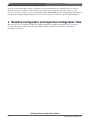
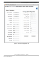
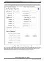
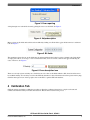
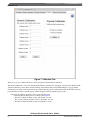
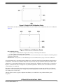
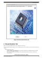
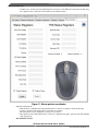
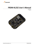
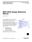
Freescale Semiconductor
User Guide
Document Number:CRTOUCHGUIUG
Rev 3, 07/2013
CRTouch GUI User Guide
Contents
1 Introduction
1
Introduction................................................................1
This GUI application is to be used with the CRTouch device.
The GUI configures and demonstrates CRTouch capabilities,
such as rotate, pinch, and slide gesture recognition. The GUI
uses the serial port to communicate with the CRTouch device.
It has six tabs that have the following features:
2
Port Settings Tab.......................................................1
3
Resistive Configuration and Capacitive
Configuration Tabs....................................................2
4
Calibration Tab..........................................................5
5
Gestures Tab.............................................................8
6
Mouse Emulation Tab...............................................9
7
System Requirements..............................................11
8
References...............................................................11
9
Revision History.....................................................11
•
•
•
•
•
Port Settings for the CDC serial port configurations
Resistive Configuration
Calibration for single touch and multi-touch
Gestures for demonstration on multi-touch gestures
Mouse Emulation which shows one of the applications
that can be achieved with the CRTouch device
2 Port Settings Tab
The serial port settings are:
• baud rate — 115200
• data bits — 8
• stop bits — 1
• parity — odd
• flow control — none
This GUI will try to communicate with the CRTouch device,
always using the above configuration. The serial port number
can be selected from the "Select Com Port" drop down box. If
for any reason the baud rate configured on the CRTouch
© 2013 Freescale Semiconductor, Inc.
Resistive Configuration and Capacitive Configuration Tabs
device does not match the GUI’s baud rate, a baud rate auto detection mechanism starts. The GUI asks you to enter the
CRTouch device into a baud rate auto detection mode. See the data sheet titled CR Touch Data Sheet Capacitive and
Resistive Touch Sensing Application Specific IC (document number CRTOUCHDS) for more information about the baud rate
auto detection mechanism. Click the interrogation icon on the top right corner of the GUI to open the CRTouch datasheet.
3 Resistive Configuration and Capacitive Configuration Tabs
These tabs allow you to customize the CRTouch for different applications and different hardware. Figure 1 and Figure 2
show tabs which allow readings to know the current CRTouch device configuration, and writings to customize the
performance of the device.
CRTouch GUI User Guide, Rev 3, 07/2013
2
Freescale Semiconductor, Inc.
Resistive Configuration and Capacitive Configuration Tabs
Figure 1. Resistive Configuration Tab
CRTouch GUI User Guide, Rev 3, 07/2013
Freescale Semiconductor, Inc.
3
Resistive Configuration and Capacitive Configuration Tabs
Figure 2. Capacitive Configuration tab
One or several registers can be modified at the same time. To modify a register, change the value shown on the register field
and click on the change button. A pop up window appears if an error arises while a reading or writing is in progress. This
window indicates the register name that causes the error and also the cause of the error. See Figure 3.
CRTouch GUI User Guide, Rev 3, 07/2013
4
Freescale Semiconductor, Inc.
Calibration Tab
Figure 3. Error reporting
A help description of each field is shown by placing the cursor over the field. See Figure 4.
Figure 4. Help description
Many registers are bit fields and each bit can be modified by clicking on it. Each click toggles the bit from 0 to 1 and from 1
to 0. See Figure 5.
Figure 5. Bit fields
The remaining registers that are not bit fields must be written with the desired value by typing a decimal value. If the fields
are empty, the value is out of range, or it is not in decimal format, an error icon next to the text box appears indicating the
cause of the error. See Figure 6.
Figure 6. Error description icon
There are read only registers and they are colored in brown. Also there are bit fields marked as N/A, these bit fields can not
be modified and they are read always as 0. See the CRTouch datasheet for more information about the registers memory map.
Click the interrogation icon on the top right corner of the GUI to open the CRTouch datasheet.
4 Calibration Tab
CRTouch requires performing a calibration procedure to adjust the coordinates detection for a single touch event and
calibrates the internal circuitry for multi-touch detection. This tab will be useful for the process.
CRTouch GUI User Guide, Rev 3, 07/2013
Freescale Semiconductor, Inc.
5
Calibration Tab
Figure 7. Calibration Tab
There are two ways to calibrate the device, namely the physical and the numeric calibration.
The physical calibration is a more user friendly method which is started by choosing single or multi-touch calibration at the
"Physical Calibration" section in this tab after clicking on the Calibrate button. The GUI then displays a pop up window
showing the point of the touch screen that must be touched. After the point is touched and released, the GUI shows the next
point where the user must touch. The pop up window disappears after the calibration process ends.
• The physical calibration procedure consists of the following steps:
• Detecting three X and Y pairs of coordinates (See Figure 8).
• The first coordinate should be at 10% of X and 10% of Y axis.
• The second coordinate should be at 50% of X and 90% of Y axis.
• The third coordinate should be at 90% of X and 50% of Y axis.
CRTouch GUI User Guide, Rev 3, 07/2013
6
Freescale Semiconductor, Inc.
Calibration Tab
Figure 8. Single Touch Calibration Points
• When multi-touch detection is enabled, there will be two pairs of multi-touch coordinates that have to be touched (See
Figure 9).
Figure 9. Multi-touch Calibration Points
• RECOMMENDATIONS:
• Use a stylus or a different item to improve the accuracy for the single touch detection.
• Use the fingers for the multi-touch coordinates.
• NOTE: For optimal multi-touch gestures detection, the screen resolution must also be configured to match the physical
proportions of the screen.
• IMPORTANT: You may have to do the calibration process several times before you get to the correct calibration.
A less user-friendly way to trigger the physical calibration is to set the bit 6 on the Trigger Events Register at the "Resistive
Configuration" tab. If this bit is set and the change button is pressed, the same pop up window displays as described earlier.
Alternatively, to ensure that the Resistive Screen is properly calibrated, the “Calibration error detected” bit on “Status Error
Register” (found at the “Resistive Configuration” tab) is disabled (0) and the “Resistive touch screen calibrated” bit in the
“Status Register2” is enabled (1).
The numeric calibration method can be done by directly entering the calibration constants into the fields at the "Numeric
Calibration" section, then clicking on the “Change” button and verifying that the entered calibration constants are the same
after clicking on the “Read” button.
After the resistive screen is properly configured and calibrated, you shouldn’t have any problems with the gesture
recognition.
CRTouch GUI User Guide, Rev 3, 07/2013
Freescale Semiconductor, Inc.
7
Gestures Tab
5 Gestures Tab
This tab demonstrates clockwise, counterclockwise rotation, zoom in, zoom out, vertical, and horizontal slide gestures if they
are configured on the “Resistive Configuration” tab. The demonstration uses multi-touch gestures.
This window requires that the calibration procedure, including the multi-touch calibration, has already been performed.
• Gesture Procedure:
• Press the start button to begin the gesture demonstration.
• The GUI will send reading requests through the UART port as fast as possible until the stop button is
pressed.
• While the demonstration is running, you should be able to rotate (clockwise and counterclockwise), zoom
(in and out), and slide (vertically and horizontally) the image on the screen.
• Press the stop button to end the demonstration and stop the communication with the CRTouch device.
• NOTE: The slide gesture takes effect only when the image size is greater than the original size. See the CRTouch
datasheet for more information about how to perform a gesture using the touch screen. Click the interrogation icon on
the top right corner of the GUI to open the CRTouch datasheet.
CRTouch GUI User Guide, Rev 3, 07/2013
8
Freescale Semiconductor, Inc.
Mouse Emulation Tab
Figure 10. Gesture demonstration tab
6 Mouse Emulation Tab
This tab shows how the CRTouch device can be configured as a mouse pad.
The mouse emulation window takes the X and Y coordinates from the resistive touch screen as if it was the mouse input for a
computer.
• Mouse Emulation Procedure:
• After the “Enable” mouse emulation button is pressed the computer mouse is inhibited and the mouse pointer
must be moved through the touch pad.
• Move the mouse pointer over the “Disable” mouse emulation button and press left click to end the mouse
emulation mode.
CRTouch GUI User Guide, Rev 3, 07/2013
Freescale Semiconductor, Inc.
9
Mouse Emulation Tab
• Another way to do this is pressing and holding the reset button on the CRTouch evaluation board and using
the computer mouse to left click on the disable mouse emulation button.
Figure 11. Mouse pointer coordinates
• Optional Configurations:
• This tab allows configuring the touch pad with relative or absolute coordinates. Check the “Relative
Position” check box if the touch pad is not mounted over a display.
• The slide gesture can be configured to scroll up or scroll down.
• The capacitive electrode 0 and electrode 1 can also be configured as keypad to perform a left click and right
click, respectively.
• RECOMMENDATIONS:
CRTouch GUI User Guide, Rev 3, 07/2013
10
Freescale Semiconductor, Inc.
System Requirements
• Check the “Refresh Registers” check box to refresh the status register fields periodically. This option can
be disabled to improve the mouse pointer detection.
• It is recommended that the screen resolution matches with the horizontal and vertical resolution values in
the CRTouch settings.
• Use the stylus for a better performance of the mouse emulation.
7 System Requirements
• USB-to-SERIAL Driver
• You must have installed on your computer the USB-to-SERIAL driver before you try to use the GUI.
• The installer for version 2.1 includes the driver. To obtain the most recent driver version, download it at
freescale.com/usb2ser.
• .NET Framework 4.0 or newer
• You must have installed on your computer a .NET Framework version 4.0 or greater. Otherwise, you will not be
able to run the application. Go to microsoft.com/download/ en/details.aspx?id=17851 to download the .NET
Framework version 4.0
8 References
http://www.freescale.com/CRTOUCH
9 Revision History
Date
Change Description
03/2013
Rev. 1
06/2013
Updated to describe changes on CRTouch GUI software tool
version 2.1
07/2013
Integrated document EVBCRTOUCH USER GUIDE v0.2
from Jose Reyes.
CRTouch GUI User Guide, Rev 3, 07/2013
Freescale Semiconductor, Inc.
11
How to Reach Us:
Information in this document is provided solely to enable system and software
Home Page:
freescale.com
implementers to use Freescale products. There are no express or implied copyright
Web Support:
freescale.com/support
information in this document.
licenses granted hereunder to design or fabricate any integrated circuits based on the
Freescale reserves the right to make changes without further notice to any products
herein. Freescale makes no warranty, representation, or guarantee regarding the
suitability of its products for any particular purpose, nor does Freescale assume any
liability arising out of the application or use of any product or circuit, and specifically
disclaims any and all liability, including without limitation consequential or incidental
damages. “Typical” parameters that may be provided in Freescale data sheets and/or
specifications can and do vary in different applications, and actual performance may vary
over time. All operating parameters, including “typicals,” must be validated for each
customer application by customer’s technical experts. Freescale does not convey any
license under its patent rights nor the rights of others. Freescale sells products pursuant
to standard terms and conditions of sale, which can be found at the following address:
freescale.com/SalesTermsandConditions.
Freescale and the Freescale logo are trademarks of Freescale Semiconductor, Inc.,
Reg. U.S. Pat. & Tm. Off. Ready Play is a trademark of Freescale Semiconductor, Inc.
All other product or service names are the property of their respective owners.
© 2013 Freescale Semiconductor, Inc.
Document Number CRTOUCHGUIUG
Rev 3
07/2013