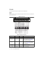
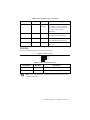
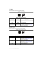
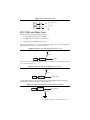
1
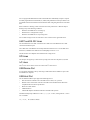
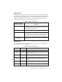
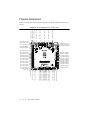
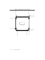
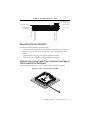
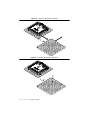
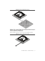
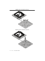
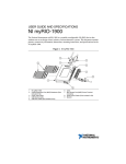
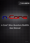
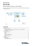
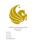
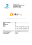
USER MANUAL
NI roboRIO
RIO Device for Robotics
The NI roboRIO is a portable reconfigurable I/O (RIO) device that students can use to design
control, robotics, and mechatronics systems used in the FIRST Robotics Competition (FRC).
This document contains pinouts, connectivity information, dimensions, and mounting
instructions for the NI roboRIO. The NI roboRIO provides the I/O shown in Figure 1 and
connects to a host computer over USB and 10/100 Ethernet.
Figure 1. NI roboRIO Features
5
6
7
8
9
10
INPUT
7-16V
45W MAX
CAN
POWER
L (GRN)
4
STATUS
H (YEL)
SPI
3.3V SDA
3
NI roboRIO
RS-232
COMM
CS0
CS1
5V
CS2
CS3
SCLK
MOSI
MISO
3.3V
SCL
2
RADIO
14
I2C
11
MODE
RSL
0
TXD
RXD
1
0
2
1
3
2
DIO
5
4
12
1
13
7
6
6
33
5
4
PWM
3
1
7
8
Y
9
9
8
Z
X
ACCELEROMETER
RELAY
RSL
S
5V
0
2
3
0
1
2
FWD
REV
S
18
1
2
3
4
5
6
7
8
9
1
ANALOG IN
Digital input and output (DIO) port
RS-232 port
I2C port
CAN port
Power connector
USB Device port
USB Host retention mount
USB Host ports
Ethernet port
RESET
3
USER
S
S
5V
17
16
10
11
12
13
14
15
16
17
18
6V
15
Serial peripheral interface bus (SPI) port
LEDs
Pulse-width modulation (PWM) port
myRIO Expansion Port (MXP)
MXP retention mount
User and Reset buttons
Analog input (AI) port
Relay port
Robot signal light (RSL) port
Contents
Safety Information .................................................................................................................... 3
Electromagnetic Compatibility Guidelines...............................................................................3
Hardware Block Diagram ......................................................................................................... 4
Setting Up the NI roboRIO ....................................................................................................... 5
Wiring Power to the NI roboRIO ..................................................................................... 5
Powering On the NI roboRIO ........................................................................................... 5
Connecting the NI roboRIO to a Network........................................................................ 6
Preparing the NI roboRIO for Competition ...................................................................... 6
User Power........................................................................................................................ 6
Pinouts ...................................................................................................................................... 8
MXP.................................................................................................................................. 8
CAN Port .......................................................................................................................... 9
I2C Port ............................................................................................................................. 10
RS-232 Port....................................................................................................................... 10
DIO Port............................................................................................................................ 11
RSL Port ........................................................................................................................... 11
Relay Port ......................................................................................................................... 12
AI Port............................................................................................................................... 12
PWM Port ......................................................................................................................... 13
SPI Port ............................................................................................................................. 13
Signal Ground References ........................................................................................................ 14
Interfaces................................................................................................................................... 14
AI Channels ...................................................................................................................... 14
AO Channels..................................................................................................................... 14
DIO, PWM, and Relay Lines............................................................................................ 15
UART and RS-232 Lines.................................................................................................. 16
SPI Lines........................................................................................................................... 16
I2C Lines ........................................................................................................................... 16
USB Device Port............................................................................................................... 16
USB Host Port .................................................................................................................. 16
Accelerometer ........................................................................................................................... 17
Converting Raw Data Values to Voltage.................................................................................. 17
Front Panel Buttons .................................................................................................................. 17
Reset Button...................................................................................................................... 17
User Button ....................................................................................................................... 18
LED Indications ........................................................................................................................ 18
Power LED ....................................................................................................................... 18
Status LED........................................................................................................................ 19
Radio LED ........................................................................................................................ 19
Comm LED....................................................................................................................... 20
Mode LED ........................................................................................................................ 20
RSL (Safety) LED ............................................................................................................ 21
Physical Dimensions................................................................................................................. 22
2
|
ni.com
|
NI roboRIO User Manual
Mounting the NI roboRIO ........................................................................................................ 25
Method One: Using Cable Ties to Secure One Edge of the
NI roboRIO to Perfboard............................................................................................... 25
Method Two: Using Cable Ties to Secure One Corner of the
NI roboRIO to Perfboard............................................................................................... 27
Method Three: Using Screws to Secure the Bottom of the
NI roboRIO to a Metal Plate ......................................................................................... 30
Compatible USB and Ethernet Cables...................................................................................... 30
Warranty ................................................................................................................................... 31
Worldwide Support and Services ............................................................................................. 31
Safety Information
Do not operate the hardware in a manner not specified in the user
documentation. Misuse of the hardware can result in a hazard. You can compromise
the safety protection if the hardware is damaged in any way. If the hardware is
damaged, contact National Instruments for repair.
Caution
Clean the hardware with a soft, nonmetallic brush. Make sure that the hardware is completely
dry and free from contaminants before returning it to service.
Electromagnetic Compatibility Guidelines
This product was tested and complies with the regulatory requirements and limits for
electromagnetic compatibility (EMC) stated in the product specifications. These requirements
and limits provide reasonable protection against harmful interference when the product is
operated in the intended operational electromagnetic environment.
This product is intended for use in industrial locations. However, harmful interference may
occur in some installations, when the product is connected to a peripheral device or test object,
or if the product is used in residential or commercial areas. To minimize interference with radio
and television reception and prevent unacceptable performance degradation, install and use this
product in strict accordance with the instructions in the product documentation.
Furthermore, any modifications to the product not expressly approved by National Instruments
could void your authority to operate it under your local regulatory rules.
Caution To ensure the specified EMC performance, the maximum length for DIO,
RS-232, I2C, CAN, SPI, PWM, AI, Relay, and RSL signal wires is 2.0 m (6.56 ft).
The maximum length for USB cables is 5.0 m (16.40 ft). The maximum length for
Ethernet cables is 30.0 m (98.43 ft). Refer to the Compatible USB and Ethernet
Cables section of this document for information about compatible USB and Ethernet
cables.
NI roboRIO User Manual
|
© National Instruments
|
3
Hardware Block Diagram
Figure 2 shows the arrangement and functions of NI roboRIO components.
Figure 2. NI roboRIO Hardware Block Diagram
SPI Port
USB
Hosts
Port
USB
Device
Port
10/100
Ethernet
Port
2
7
SPI
+3.3 V +5.0 V
7
Xilinx Zynq-7020
CAN
Port
Power LED
+5.0 V
Status LED
+3.3 V
Radio LED
UART
myRIO
Expansion
Port (MXP)
16
Comm LED
16
DIO
Mode LED
2
Analog Out
RSL LED
4
Processor/FPGA
(LabVIEW RT)
Analog In
+6.0 V
10
+3.3 V
I2C
Port
2
10
PWM
I2C
Watchdog
2
RS-232
Port
Nonvolantile
Memory
RS-232
DDR3
DIO
Port
+5.0 V
10
Accelerometer
10
DIO
8
RSL
8
RSL
Port
4
|
ni.com
|
NI roboRIO User Manual
AI
Relay
RELAY
Port
+5.0 V
4
ANALOG IN
Port
Reset
Button
User
Button
PWM
Port
Setting Up the NI roboRIO
Wiring Power to the NI roboRIO
The NI roboRIO requires an external power supply that meets the specifications in the Power
Requirements section of the NI roboRIO Specifications. The NI roboRIO filters and regulates
the supplied power and provides power for all of the I/O and user voltage. The NI roboRIO has
one layer of reverse-voltage protection. Complete the following steps to connect a power supply
to the chassis.
1.
Ensure that the power supply is turned off.
Do not install or remove the power connector from the front panel of the
NI roboRIO while power is applied.
Caution
2.
Connect the positive lead of the power supply to the V terminal of the COMBICON power
connector shipped with the NI roboRIO, and tighten the terminal screw. Figure 3 shows the
terminal screws, which secure the wires in the screw terminals, and the connector screws,
which secure the power connector on the front panel.
Figure 3. NI roboRIO COMBICON Power Connector
2
1
1
Terminal Screws
V
C
2
2
Connector Screws
3.
Connect the negative lead of the power supply to the C terminal of the power connector and
tighten the terminal screw.
4.
Install the power connector on the front panel of the NI roboRIO and tighten the connector
screws.
5.
Turn on the power supply.
Powering On the NI roboRIO
When you apply power, the NI roboRIO runs a power-on self test (POST). During the POST,
the Power and Status LEDs turn on. The Status LED turns off, indicating that the POST is
complete. If the LEDs do not behave in this way when the system powers on, refer to the LED
Indications section.
NI roboRIO User Manual
|
© National Instruments
|
5
Connecting the NI roboRIO to a Network
Connect the NI roboRIO to an Ethernet network using the Ethernet port. Use a standard
Category 5 (CAT-5) or better shielded, twisted-pair Ethernet cable to connect the NI roboRIO
to an Ethernet hub, router, or directly to a computer.
Caution To prevent data loss and to maintain the integrity of your Ethernet
installation, do not use a cable longer than 30 m.
The first time you power up the chassis, it attempts to initiate a DHCP network connection. If
the chassis is unable to initiate a DHCP connection, it connects to the network with a link-local
IP address with the form 169.254.x.x.
Preparing the NI roboRIO for Competition
For information about configuring the controller for competitive use, refer to the Tutorials tab
in the Getting Started window of LabVIEW for FRC.
User Power
Table 1 describes the user voltage rails for powering external sensors and peripherals. The rails
are independent from the power supplies of internal systems, such as the processor and memory.
Table 1. NI roboRIO Voltage Rails
Voltage Rail
6
Description
+6 V
Power from PWM ports for use with servos.
+5 V
Power for DIO and AI ports for sensors, and power for the MXP for
powering expansion circuits.
+3.3 V
Power for I2C, SPI, and the MXP.
|
ni.com
|
NI roboRIO User Manual
Input Voltage Brownout Behavior
The NI roboRIO input voltage range is 7 V to 16 V. The input voltage monitoring circuit
monitors the voltage on the input voltage pin. When the input voltage drops to between 4.5 V
and 6.8 V, the NI roboRIO enters brownout mode with a staged response, as Table 2 describes.
Table 2. NI roboRIO Input Voltage Brownout Behavior
Stage
Input Voltage
Range
Behavior
1
6.3 V to 6.8 V
The +6 V voltage rail starts to drop.
2
4.5 V to 6.3 V
The NI roboRIO enters a brownout fault condition and the
following precautions are taken:
•
•
User voltage rails become disabled.
All PWM generation stops at the conclusion of the current
cycle.
• GPIOs configured as outputs go to High-Z.
• Relay control outputs are driven low.
• CAN-based motor controllers become disabled.
The following systems continue to function normally with
valid data and communication:
•
•
•
•
•
•
•
•
•
•
FPGA, processor, RAM, disk, and user code
USB power and communication
Radio, if powered by USB
Ethernet
CAN
AI and AO
I2 C
SPI
RS-232 serial
LED and RSL status lights
Stage 2 continues until the input voltage rises to greater than
7.5 V or drops to less than 4.5 V.
3
Less than 4.5 V
All controller functions cease and the controller state is lost.
This condition continues until the input voltage rises to greater
than 4.65 V, at which point the controller starts the normal
booting sequence. At startup, the controller remains in Stage 2
until the input voltage rises to greater than 7.5 V.
NI roboRIO User Manual
|
© National Instruments
|
7
Pinouts
The following describe the pins and signals on the NI roboRIO ports.
MXP
Figure 4 and Table 3 describe the MXP pins and signals. Note that some pins carry both primary
and secondary functions.
AI2
AI1
AI0
+5V
3
1
34 32 30 28 26 24 22 20 18 16 14 12 10 8
6
4
2
AO1
AO0
UART.RX
DGND
UART.TX
DGND
DIO11 / PWM7
DGND
DGND
DIO12 / PWM8
DIO13 / PWM9
DGND
DGND
DIO14 / I2C SCL
DIO15 / I2C SDA
33 31 29 27 25 23 21 19 17 15 13 11 9
DGND
5
AI3
7
AGND
DIO0 / PWM0
DIO1 / PWM1
DIO2 / PWM2
DIO3 / PWM3
DIO5 / SPI CLK
DIO4 / SPICS
DIO6 / SPI MISO
DIO8 / PWM4
DIO7 / SPI MOSI
DIO9 / PWM5
+3.3V
DIO10 / PWM6
Figure 4. MXP Pinout
Table 3. MXP Signal Descriptions
8
Signal Name
Reference
Direction
+5V
DGND
Output
AI <0..3>
AGND
Input
0 to 5 V, referenced, single-ended AI
channels. Refer to the AI Channels
section for more information.
AO <0..1>
AGND
Output
0 to 5 V referenced, single-ended AO.
Refer to the AO Channels section for
more information.
AGND
—
—
+3.3V
DGND
Output
|
ni.com
|
NI roboRIO User Manual
Description
+5 V power output.
Reference for AI and AO.
+3.3 V power output.
Table 3. MXP Signal Descriptions (Continued)
Signal Name
Reference
Direction
DIO <0..15>
DGND
Input or
Output
UART.RX
DGND
Input
UART.TX
DGND
Output
DGND
—
—
Description
General-purpose digital lines with
3.3 V output, 3.3 V/5 V-compatible
input. Refer to the DIO, PWM, and
Relay Lines section for more
information.
UART receive input. UART lines are
electrically identical to DIO lines.
UART transmit output. UART lines are
electrically identical to DIO lines.
Reference for digital signals, +5 V,
and +3.3 V.
CAN Port
Figure 5 and Table 4 describe the CAN port pins and signals.
Figure 5. CAN Port Pinout
L (GRN)
H (YEL)
Table 4. CAN Port Signal Descriptions
Signal Name
Direction
Description
L (GRN)
Input/Output
CAN bus differential low signal.
H (YEL)
Input/Output
CAN bus differential high signal.
Note The NI roboRIO contains an internal 120 W termination resistor between
L (GRN) and H (YEL).
NI roboRIO User Manual
|
© National Instruments
|
9
I2C Port
Figure 6 and Table 5 describe the I2C port pins and signals.
Figure 6. I2C Port Pinout
3.3V SDA
SCL
Table 5. I2C Port Signal Descriptions
Signal Name
Direction
GND
—
3.3V
Output
SCL
Input or Output
SDA
Input or Output
Description
Reference for digital lines and +3.3 V power
output.
+3.3 V power output.
I2C lines with 3.3 V output, 3.3 V/
5 V-compatible input. Refer to the I2C Lines
section for more information.
RS-232 Port
Figure 7 and Table 6 describe the RS-232 port pins and signals.
Figure 7. RS-232 Serial Port Pinout
TXD
RXD
Table 6. RS-232 Serial Port Signal Descriptions
10
|
Signal Name
Direction
Description
TXD
Output
Serial transmit output with ±5 V to ±15 V signal
levels. Refer to the UART and RS-232 Lines
section for more information.
RXD
Input
GND
—
ni.com
|
NI roboRIO User Manual
Serial receive input with ±15 V input voltage
range. Refer to the UART and RS-232 Lines
section for more information.
Reference for digital lines.
DIO Port
Figure 8 and Table 7 describe the DIO port pins and signals.
Figure 8. DIO Port Pinout
1
2
3
4
5
6
8
7
9
5V
S
0
Table 7. DIO Port Signal Descriptions
Signal Name
Direction
Description
S (DIO) <0..9>
Input/Output
General-purpose digital lines with 3.3 V output,
3.3 V/5 V-compatible input. Refer to the DIO,
PWM, and Relay Lines section for more
information.
5V
Output
GND
—
+5 V power output.
Reference for digital lines and +5 V power
output.
RSL Port
Figure 9 and Table 8 describe the RSL port pins and signals.
Figure 9. RSL Port Pinout
S
Table 8. RSL Port Signal Descriptions
Signal Name
Direction
Description
S
Output
Switched power output to drive RSL when
RSLis enabled. The voltage level depends on the
connected input voltage. RSL current is limited
at 120 mA.
GND
—
Reference for S.
NI roboRIO User Manual
|
© National Instruments
|
11
Relay Port
Figure 10 and Table 9 describe the Relay port pins and signals.
Figure 10. Relay Port Pinout
1
0
2
3
FWD
REV
Table 9. Relay Port Signal Descriptions
Signal Name
Direction
Description
FWD <0..3>
Output
Relay digital lines with 5 V output.
REV <0..3>
Output
Relay digital lines with 5 V output.
GND
—
Reference for digital lines.
AI Port
Figure 11 and Table 10 describe the AI port pins and signals.
Figure 11. AI Port Pinout
0
1
2
3
S
5V
Table 10. AI Port Signal Descriptions
12
|
Signal Name
Direction
Description
S (AI) <0..3>
Input
0 V to 5 V referenced, single-ended AI channels.
Refer to the AI Channels section for more
information.
5V
Output
GND
—
ni.com
|
NI roboRIO User Manual
+5 V power output.
Reference for AI and +5 V power.
PWM Port
Figure 12 and Table 11 describe the PWM port pins and signals.
Figure 12. PWM Port Pinout
9
8
7
6
5
4
3
2
1
0
S
6V
Table 11. PWM Port Signal Descriptions
Signal Name
Direction
Description
S (PWM) <0..9>
Output
PWM digital lines with 5 V output.
6V
Output
+6 V power output for servos only.
GND
—
Reference for digital lines and +6 V power
output.
SPI Port
Figure 13 and Table 12 describe the SPI port pins and signals.
Figure 13. SPI Port Pinout
SCLK
MOSI
MISO
3.3V
CS0
CS1
5V
CS2
CS3
Table 12. SPI Port Signal Descriptions
Signal Name
Direction
Description
3.3V
Output
+3.3 V power output.
5V
Output
+5 V power output.
CS <0..3>
Output
SCLK
Output
SPI with 3.3 V output, 3.3 V/5 V-compatible
input. Refer to the SPI Lines section for more
information.
MOSI
Output
MISO
Input
GND
—
Reference for digital lines and +3.3 V and
+5.5 V power output.
NI roboRIO User Manual
|
© National Instruments
|
13
Signal Ground References
To minimize noise on analog measurement channels, use the ground reference of the
corresponding port. For example, when you are using AI, the measurement should reference the
GND of the AI port.
Interfaces
AI Channels
The NI roboRIO has AI channels on the MXP and on the AI port. The channels are multiplexed
to a single analog-to-digital converter (ADC) that samples all channels.
The MXP and the AI port each has four single-ended AI channels, AI0-AI3, which you can use
to measure 0-5 V signals.
Note For important information about improving measurement accuracy by
reducing noise, visit ni.com/info and enter the Info Code analogwiring.
Figure 14 shows the AI topology of the NI roboRIO.
Figure 14. NI roboRIO AI Circuitry
Expansion port
AI0
AI1
AI2
AI3
0–5 V
Integrated AI port
MUX
ADC
AI0
AI1
AI2
AI3
AO Channels
The NI roboRIO MXP has two AO channels, AO0 and AO1, which you can use to generate
signals of 0 V to 5 V. Each channel has a dedicated digital-to-analog converter (DAC), which
allows all AO channels to update simultaneously. The maximum update rate is specified as an
aggregate rate in the Analog Output section of the NI roboRIO Specifications.
Figure 15 shows the AO topology of the NI roboRIO.
14
|
ni.com
|
NI roboRIO User Manual
Figure 15. NI roboRIO AO Circuitry
DAC
Expansion port
AO0
0–5 V
DAC
AO1
DIO, PWM, and Relay Lines
The NI roboRIO provides the following DIO lines:
•
3.3 V general-purpose DIO lines on the MXP
•
3.3 V digital lines on the DIO, I2C, and SPI ports
•
5 V digital lines on the PWM and Relay ports.
DIO <9..0> on the DIO port, CS <3..0> on the SPI port, and DIO <13..0> on the MXP all have
40 kΩ pullup resistors to 3.3 V, as shown in Figure 16.
Figure 16. DIO Lines with 40 kΩ Pullup Resistors to 3.3 V
+3.3 V
40 kΩ
FPGA
Bus Switch
DIO/CS
DIO <15..14> on the MXP and the two lines on the I2C port all have 2.2 kΩ pullup resistors to
3.3 V, as shown in Figure 17.
Figure 17. DIO Lines with 2.2 kΩ Pullup Resistors to 3.3 V
+3.3 V
2.2 kΩ
FPGA
Bus Switch
DIO/SCL/SDA
<SCLK, MOSI, MISO> on the SPI port and the lines on the PWM and Relay ports all have
40 kΩ pulldown resistors to ground, as shown in Figure 18.
Figure 18. DIO Lines with 40 kΩ Pulldown Resistors to Ground
FPGA
Bus Switch
DIO or Other Line
40 kΩ
NI roboRIO User Manual
|
© National Instruments
|
15
You can program all MXP DIO lines and on-board DIO lines individually as inputs or outputs.
Secondary digital functions include SPI, I2C, PWM, and quadrature encoder input. Refer to the
NI roboRIO software documentation for information about configuring the behavior of the DIO
lines.
When a DIO line is floating, it floats in the direction of the pull resistor. A DIO line may be
floating in any of the following conditions:
•
When the NI roboRIO device is starting up
•
When the line is configured as an input
•
When the NI roboRIO device is powering down
You can add a stronger resistor to a DIO line to cause it to float in the opposite direction.
UART and RS-232 Lines
The NI roboRIO has one UART connected to the UART lines on the MXP and one UART
connected to the RS-232 port.
The UART lines on the MXP are electrically identical to DIO lines 0 to 13 on the MXP. Like
those lines, UART.RX and UART.TX have 40 kΩ pullup resistors to 3.3 V.
The RS-232 lines are compliant with TIA/EIA-232-F voltage levels.
SPI Lines
The SPI port can support up to four devices by using each of the four Chip Select (CS) lines.
I2C Lines
The I2C lines can be used to connect to a network of I2C slave devices..
USB Device Port
You can deploy and debug code by connecting a USB cable from the USB device port on the
NI roboRIO to a computer.
USB Host Port
The NI roboRIO USB host port supports the following devices:
•
Web cameras that conform to the USB Video Device Class (UVC) protocol.
•
Machine vision cameras that conform to the USB3 Vision standard and are backward
compatible with the USB 2.0 specification.
•
Basler ace USB3 cameras.
•
USB Flash drives.
•
USB-to-IDE adapters formatted with FAT16 and FAT32 file systems.
LabVIEW usually maps USB devices to the /U, /V, /W, or /X drive, starting with the /U drive
if it is available.
16
|
ni.com
|
NI roboRIO User Manual
Accelerometer
The NI roboRIO contains a three-axis accelerometer, MMA8452Q. Refer to the Accelerometer
section of the NI roboRIO Specifications for the accelerometer sample rates.
Converting Raw Data Values to Voltage
You can use the following equations to convert raw data values to volts:
V = Raw Data Value * LSB Weight
LSB Weight = Nominal Range ÷ 2ADC Resolution
where Raw Data Value is the value returned by reading in the input channel,
LSB Weight is the value in volts of the increment between data values,
Nominal Range is the absolute value in volts of the full, peak-to-peak nominal range
of the channel,
and ADC Resolution is the resolution of the ADC in bits. (ADC Resolution = 12.)
•
For AI and AO channels on the MXP,
LSB Weight = 5 V ÷ 212 = 1.221 mV
Maximum reading = 4095 * 1.221 mV = 4.999 V
•
For the accelerometer,
LSB Weight = 16 g ÷ 212 = 3.906 mg
Maximum Positive Reading = +2047 * 3.906 mg = +7.996 g
Maximum Negative Reading = -2048 * 3.906 mg = -8.000 g
Front Panel Buttons
Reset Button
Pressing and releasing the Reset button restarts the processor and the FPGA.
Pressing and holding the Reset button until the status LED lights (about five seconds) and then
releasing the Reset button restarts the processor and the FPGA and forces the NI roboRIO into
safe mode. In safe mode, the NI roboRIO launches only the services necessary for updating
configuration and installing software.
When the NI roboRIO is in safe mode, you can communicate with it by using the serial lines on
the RS-232 serial port. You must configure your serial-port terminal program with the following
settings:
•
115,200 bits per second
•
Eight data bits
NI roboRIO User Manual
|
© National Instruments
|
17
•
No parity
•
One stop bit
•
No flow control
User Button
The User Button produces a logic TRUE when depressed and a logic FALSE when not
depressed. The User Button is not debounced in hardware.
LED Indications
Power LED
The Power LED is a tri-color red/green/yellow LED that indicates specific conditions, as shown
in Table 13.
Table 13. Power LED Indications
18
|
Color
State
Off
Off
Green
Solid
Power is valid with no fault condition.
Red
Solid
Fault condition detected. One or more user voltage rails are
in short-circuit or overcurrent condition.
Red
Flashing
Yellow
Solid
ni.com
|
Indication
Power is outside valid input range.
The input voltage is too high (greater than 16 V) and all
outputs, including the RSL output, are disabled.
Brownout condition detected. The 6 V user rail and
outputs are disabled.
NI roboRIO User Manual
Status LED
The Status LED is a single-color yellow LED. The Status LED is off during normal operation.
The NI roboRIO runs a power-on self test (POST) when you apply power to the device. During
the POST, the Power and Status LEDs turn on. When the Status LED turns off, the POST is
complete. The NI roboRIO indicates specific error conditions by flashing the Status LED a
certain number of times every few seconds, as shown in Table 14.
Table 14. Status LED Indications
Number of Flashes
Every Few Seconds
Indication
2
The device has detected an error in its software. This usually
occurs when an attempt to upgrade the software is interrupted.
Reinstall software on the device.
3
The device is in safe mode.
4
The software has crashed twice without rebooting or cycling
power between crashes. This usually occurs when the device runs
out of memory. Review your RT VI and check the memory usage.
Modify the VI as necessary to solve the memory usage issue.
Continuously flashing
or solid
The device has detected an unrecoverable error. Contact National
Instruments.
Radio LED
The Radio LED is a tri-color red/green/yellow LED that indicates specific conditions for an
USB-connected radio, as shown in Table 15.
Table 15. Radio LED Indications
Color
State
Indication
Off
Off
Yellow
Blinking
Booting as access point. Radio is enabled and access point
is being constructed.
Yellow
Solid
Access point active. Radio is enabled and in access point
mode.
Green
Blinking
Green
Solid
Bridge active. Radio is enabled and has bridge configured
with SSID settings.
Red
Any
Reserved.
No connection detected.
Booting as bridge. Radio is enabled and bridging is in
progress.
NI roboRIO User Manual
|
© National Instruments
|
19
Other LED states may indicate other, undetermined radio issues or failures. This LED is
undefined if a USB radio is not used.
Comm LED
The Comm LED is a tri-color red/green/yellow LED that indicates robot communication
conditions, as shown in Table 16.
Table 16. Comm LED Indications
Color
State
Indication
Off
Off
Red
Solid
No code. The protocol indicates that no user code has been
loaded.
Red
Blinking
E-Stop. The protocol indicates that the driver station has
E-Stopped the robot.
Green
Solid
Active. The protocol is active and the driver station is in
control of the robot.
Yellow
Any
Reserved.
No communication detected. No heartbeat detected.
Mode LED
The Mode LED is a tri-color red/green/yellow LED that indicates the mode of the NI roboRIO
outputs, as shown in Table 17.
Table 17. Mode LED Indications
20
|
Color
State
Off
Off
Green
Solid
Outputs enabled. Autonomous mode.
Yellow
Solid
Outputs enabled. TeleOperated mode.
Red
Solid
Outputs unknown, undetermined, or in test mode.
ni.com
|
Indication
Outputs disabled.
NI roboRIO User Manual
RSL (Safety) LED
The RSL LED is a single-color yellow LED that functions identically to the RSL, which is an
external indicator connected to the NI roboRIO using a dedicated connector, and indicates
specific conditions, as shown in Table 18.
Table 18. RSL LED Indications
Color
State
Indication
Off
Off
Yellow
Solid
Outputs disabled. Robot is powered.
Yellow
Blinking
Outputs enabled. Robot is powered.
Outputs disabled. No power.
NI roboRIO User Manual
|
© National Instruments
|
21
Physical Dimensions
Figures 19 through 22 describe the physical dimensions of the NI roboRIO enclosure and its
features.
135.47 mm (5.333 in.)
132.61 mm (5.221 in.)
130.72 mm (5.147 in.)
116.64 mm (4.592 in.)
94.67 mm (3.727 in.)
74.55 mm (2.935 in.)
49.45 mm (1.947 in.)
29.58 mm (1.164 in.)
9.71 mm (0.382 in.)
8.93 mm (0.352 in.)
8.44 mm (0.332 in.)
Figure 19. NI roboRIO Dimensions, Primary Side
INPUT
7-16V
45W MAX
CAN
POWER
L (GRN)
STATUS
H (YEL)
123.43 mm (4.860 in.)
SPI
3.3V SDA
110.96 mm (4.368 in.)
I2C
SCL
99.54 mm (3.919 in.)
NI roboRIO
RS-232
RADIO
COMM
CS0
CS1
5V
CS2
CS3
SCLK
MOSI
MISO
3.3V
MODE
RSL
TXD
RXD
0
1
2
2
3
DIO
4
5
4
PWM
3
5
6
7
6
7
8
9
9
Z
X
ACCELEROMETER
RELAY
0
1
2
ANALOG IN
3
0
1
2
RESET
3
FWD
REV
USER
S
NI roboRIO User Manual
6V
117.85 mm (4.64 in.)
8.09 mm (0.319 in.)
128.01 mm (5.040 in.)
60.38 mm (2.377 in.)
68.00 mm (2.677 in.)
73.08 mm (2.877 in.)
78.15 mm (3.077 in.)
85.77 mm (3.377 in.)
93.39 mm (3.677 in.)
101.01 mm (3.977 in.)
S
5V
45.14 mm (1.777 in.)
52.76 mm (2.077 in.)
S
22.26 mm (0.876 in.)
0.0 mm (0 in.)
S
8.44 mm (0.332 in.)
5V
137.72 mm (5.422 in.)
8
|
1
33
RSL
8.42 mm (0.332 in.)
7.16 mm (0.282 in.)
0.0 mm (0 in.)
ni.com
65.64 mm (2.584 in.)
58.02 mm (2.284 in.)
54.40 mm (1.984 in.)
42.78 mm (1.684 in.)
42.58 mm (1.677 in.)
35.16 mm (1.384 in.)
27.54 mm (1.084 in.)
19.92 mm (0.784 in.)
Y
19.52 mm (0.769 in.)
|
80.88 mm (3.184 in.)
74.70 mm (2.941 in.)
1
65.24 mm (2.569 in.)
57.62 mm (2.269 in.)
50.00 mm (1.969 in.)
42.38 mm (1.669 in.)
34.76 mm (1.369 in.)
27.14 mm (1.069 in.)
22
88.50 mm (3.484 in.)
0
88.10 mm (3.469 in.)
80.48 mm (3.169 in.)
72.86 mm (2.869 in.)
129.83 mm (5.111 in.)
129.21 mm (5.087 in.)
126.94 mm (4.998 in.)
143.68 (5.657 in.)
Figure 20. NI roboRIO Dimensions, Primary Side LEDs
143.18 mm (5.637 in.)
INPUT
7-16V
45W MAX
CAN
128.51 mm (5.059 in.)
123.51 mm (4.862 in.)
116.01 mm (4.567 in.)
111.01 mm (4.370 in.)
106.01 mm (4.173 in.)
98.51 mm (3.878 in.)
POWER
L (GRN)
STATUS
H (YEL)
SPI
3.3V SDA
I2C
NI roboRIO
RS-232
RADIO
COMM
CS0
CS1
5V
CS2
CS3
SCLK
MOSI
MISO
3.3V
SCL
MODE
RSL
0
TXD
RXD
1
0
2
1
3
2
DIO
4
5
4
PWM
3
5
1
7
6
6
33
7
8
Y
9
9
8
Z
X
ACCELEROMETER
RELAY
RSL
5V
S
S
0
FWD
REV
1
2
ANALOG IN
3
0
1
2
RESET
3
USER
S
S
5V
6V
0.0 mm (0 in.)
146.15 mm (5.754 in.)
0.0 mm (0 in.)
NI roboRIO User Manual
|
© National Instruments
|
23
3.84 mm (0.151 in.)
142.31 mm (5.603 in.)
Figure 21. NI roboRIO Dimensions, Secondary Side
4-40 Screw Insert
135.09 mm (5.319 in.)
122.39 mm (4.819 in.)
20.79 mm (0.819 in.)
8.09 mm (0.319 in.)
24
|
ni.com
|
NI roboRIO User Manual
0.0 mm (0 in.)
22.28 mm (0.877 in.)
123.88 mm (4.877 in.)
0.0 mm (0 in.)
Figure 22. NI roboRIO Dimensions, Side
34.43 mm (1.355 in.)
32.19 mm (1.267a in.)
5.71 mm (0.225 in.)
122.39 mm (4.819 in.)
129.59 mm (5.102 in.)
6.03 mm (0.238 in.)
0.0 mm (0 in.)
13.59 mm (0.535 in.)
20.79 mm (0.819 in.)
22.76 mm (0.896 in.)
0.0 mm (0 in.)
20.91 mm (0.823 in.)
Mounting the NI roboRIO
You can mount the NI roboRIO in the following ways:
•
Using cable ties to secure one edge of the NI roboRIO to perfboard with 6.35 mm (0.25 in.)
diameter holes on 12.7 mm (0.5 in.) straight centers, such as AndyMark part number
am-0836.
•
Using cable ties to secure one corner of the NI roboRIO to perfboard.
•
Using screws to secure the bottom of the NI roboRIO to a metal plate.
Method One: Using Cable Ties to Secure One Edge of
the NI roboRIO to Perfboard
Figures 23 through 26 show how to secure one edge of the NI roboRIO to perfboard.
Figure 23. Cable Ties, Method One, Step One
NI roboRIO User Manual
|
© National Instruments
|
25
Figure 24. Cable Ties, Method One, Step Two
Figure 25. Cable Ties, Method One, Step Three
26
|
ni.com
|
NI roboRIO User Manual
Figure 26. Cable Ties, Method One, Step Four
Method Two: Using Cable Ties to Secure One Corner of
the NI roboRIO to Perfboard
Figures 27 through 31 show how to secure one corner of the NI roboRIO to perfboard.
Figure 27. Cable Ties, Method Two, Step One
NI roboRIO User Manual
|
© National Instruments
|
27
Figure 28. Cable Ties, Method Two, Step Two
Figure 29. Cable Ties, Method Two, Step Three
28
|
ni.com
|
NI roboRIO User Manual
Figure 30. Cable Ties, Method Two, Step Four
Figure 31. Cable Ties, Method Two, Step Five
NI roboRIO User Manual
|
© National Instruments
|
29
Method Three: Using Screws to Secure the Bottom of
the NI roboRIO to a Metal Plate
Figure 32 shows how to secure the bottom of the NI roboRIO to a metal plate using the built-in
4-40 screw holes. The length of the screws required depends on the thickness of the plate you
use. For example, if the plate is 4.76 mm (0.188 in.) thick, the recommended screw length is
7.94 mm (0.313 in.).
Figure 32. Mounting NI roboRIO Using Screws
1
2
1
Metal Mounting Plate
2
4-40 Screws x 4
Compatible USB and Ethernet Cables
Table 19 lists the USB and Ethernet cables available from NI that you can use with the
NI roboRIO.
Table 19. Compatible USB and Ethernet Cables Available from NI
30
|
Cable
Description
NI Part Number
USB cable
USB 2.0 A/B, black, 2 m
192256A-01
Peripheral USB cable
USB 2.0 A/A, locking, black, 2 m
152166A-01
Ethernet cable
CAT-5E, thin profile, 2 m
151733A-01
ni.com
|
NI roboRIO User Manual
Warranty
For customers other than private individual users in the EU: The NI roboRIO is warranted
against defects in materials and workmanship for a period of three years from the date of
shipment, as evidenced by receipts or other documentation. National Instruments will, at its
option, repair or replace equipment that proves to be defective during the warranty period. This
warranty includes parts and labor.
For private individual users in the EU: Based on your statutory rights, National Instruments
will—through its distributor—cure defects in materials and workmanship within two years from
delivery.
Worldwide Support and Services
The National Instruments website is your complete resource for technical support. At ni.com/
support you have access to everything from troubleshooting and application development
self-help resources to email and phone assistance from NI Application Engineers.
Visit ni.com/services for NI Factory Installation Services, repairs, extended warranty, and
other services.
Visit ni.com/register to register your National Instruments product. Product registration
facilitates technical support and ensures that you receive important information updates from NI.
A Declaration of Conformity (DoC) is our claim of compliance with the Council of the European
Communities using the manufacturer’s declaration of conformity. This system affords the user
protection for electromagnetic compatibility (EMC) and product safety. You can obtain the DoC
for your product by visiting ni.com/certification. If your product supports calibration,
you can obtain the calibration certificate for your product at ni.com/calibration.
National Instruments corporate headquarters is located at 11500 North Mopac Expressway,
Austin, Texas, 78759-3504. National Instruments also has offices located around the world. For
telephone support in the United States, create your service request at ni.com/support or dial
1 866 ASK MYNI (275 6964). For telephone support outside the United States, visit the
Worldwide Offices section of ni.com/niglobal to access the branch office websites, which
provide up-to-date contact information, support phone numbers, email addresses, and current
events.
Refer to the NI Trademarks and Logo Guidelines at ni.com/trademarks for more information on National Instruments trademarks. Other
product and company names mentioned herein are trademarks or trade names of their respective companies. For patents covering National
Instruments products/technology, refer to the appropriate location: Help»Patents in your software, the patents.txt file on your media, or the
National Instruments Patents Notice at ni.com/patents. You can find information about end-user license agreements (EULAs) and third-party
legal notices in the readme file for your NI product. Refer to the Export Compliance Information at ni.com/legal/export-compliance
for the National Instruments global trade compliance policy and how to obtain relevant HTS codes, ECCNs, and other import/export data. NI MAKES
NO EXPRESS OR IMPLIED WARRANTIES AS TO THE ACCURACY OF THE INFORMATION CONTAINED HEREIN AND SHALL NOT BE LIABLE FOR
ANY ERRORS. U.S. Government Customers: The data contained in this manual was developed at private expense and is subject to the applicable
limited rights and restricted data rights as set forth in FAR 52.227-14, DFAR 252.227-7014, and DFAR 252.227-7015.
© 2014 National Instruments. All rights reserved.
374474A-01
Oct14