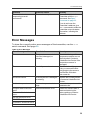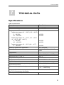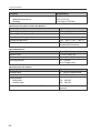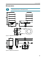
1
USER'S GUIDE
Vaisala HMDW110 Series Humidity and
Temperature Transmitters
M211726EN-C
PUBLISHED BY
Vaisala Oyj
Street address:
Mailing address:
Phone:
Fax:
Vanha Nurmijärventie 21, FI-01670 Vantaa, Finland
P.O. Box 26, FI-00421 Helsinki, Finland
+358 9 8949 1
+358 9 8949 2227
Visit our Internet pages at www.vaisala.com.
© Vaisala 2015
No part of this manual may be reproduced, published or publicly displayed in
any form or by any means, electronic or mechanical (including photocopying),
nor may its contents be modified, translated, adapted, sold or disclosed to a third
party without prior written permission of the copyright holder. Translated
manuals and translated portions of multilingual documents are based on the
original English versions. In ambiguous cases, the English versions are
applicable, not the translations.
The contents of this manual are subject to change without prior notice.
This manual does not create any legally binding obligations for Vaisala towards
customers or end users. All legally binding obligations and agreements are
included exclusively in the applicable supply contract or the General Conditions
of Sale and General Conditions of Service of Vaisala.
Table of Contents
1 General Information
About This Document
Documentation Conventions
Safety
ESD Protection
Recycling
Regulatory Compliances
Trademarks
Software License
Warranty
3
3
3
4
4
4
5
5
5
6
2 Product Overview
HMDW110 Series Overview
Output Parameters Explained
HMD110/112 Parts
HMW110/112 Parts
HMS110/112 Parts
Component Board
Analog Output Overrange Behavior
7
7
8
9
10
11
12
13
3 Installation
Selecting Location
HMD110/112 Installation
HMW110/112 Installation
HMS110/112 Installation
Wiring HMDW110
Wiring Both Current Loops With a Single Power Supply
HMDW110 Power Supply Requirements
Wiring HMDW110 with RDP100
14
14
15
17
18
20
21
21
22
4 Service Port
Connecting to the Service Port
Terminal Application Settings
Serial Commands
Device Information and Status
Serial Line Output and Communication
Measurement Output
Measurement Output Format
Serial Line Communication
Analog output
Calibration and Adjustment Commands
23
23
24
25
27
30
30
32
33
36
39
1
Other Commands
42
5 Maintenance
Cleaning
Calibration and Adjustment
Adjustment Types
Adjustment Points
Calibration and Adjustment Using a Hand-Held Meter and a
Reference Probe
One-Point Humidity Calibration and Adjustment Using a Hand-Held
Meter and HMK15 Humidity Calibrator
Two-Point Humidity Calibration and Adjustment using a computer
and a HMK15 Humidity Calibrator
Two-Point Temperature Calibration and Adjustment using a
Computer
Replacing the HUMICAP® Sensor on HMD110/112 and
HMW110/112
Replacing the HUMICAP® Sensor on HMS110/112
Filter Selection
44
44
44
45
45
6 Troubleshooting
Problem Situations
Error Messages
Unknown serial settings
Technical Support
58
58
59
60
60
7 Technical Data
Specifications
Dimensions
Spare Parts and Accessories
61
61
63
64
2
46
48
49
52
55
56
57
1 General Information
1
GENERAL INFORMATION
About This Document
This document provides information for installing, operating, and maintaining
HMDW110 series transmitters.
Table 1 Version Information
Document Code
Description
M211726EN-C
This document. August 2015. Updated the temperature
measurement accuracy specification to ±0.2 °C at +20 °C (+68
°F). Added information about the different filter options (porous
or membrane filter, depending on probe model).
M211726EN-B
Previous version. September 2014. Applicable from transmitter
software version 1.0.7 onward. Added cdate and ctext
commands. Added section Regulatory Compliances on page 5.
Updated section Troubleshooting on page 58. Updated list of
spare parts and accessories.
M211726EN-A
July 2014. First version.
Table 2 Related Documents
Document Code
Description
M211692EN
HMDW110 Series Quick Guide
M210297EN
HM70 User's Guide
M210185EN
HMK15 User's Guide
M211691EN
RDP100 User's Guide
Documentation Conventions
Warning alerts you to a serious hazard. If you do not read and
follow instructions very carefully at this point, there is a risk of
injury or even death.
3
1 General Information
Caution warns you of a potential hazard. If you do not read and
follow instructions carefully at this point, the product could be
damaged or important data could be lost.
Note highlights important information on using the product.
Safety
The HMDW110 series transmitter delivered to you has been tested for safety
and approved as shipped from the factory. Note the following precautions:
Do not modify the unit. Improper modification can damage the
product or lead to malfunction.
ESD Protection
Electrostatic Discharge (ESD) can cause immediate or latent damage to
electronic circuits. Vaisala products are adequately protected against ESD for
their intended use. It is possible to damage the product, however, by delivering
electrostatic discharges when touching, removing, or inserting any objects
inside the equipment housing.
To make sure you are not delivering high static voltages yourself, avoid touching
exposed component contacts during installation and maintenance.
Recycling
Recycle all applicable material.
Dispose of the unit according to statutory regulations. Do not
dispose of with regular household refuse.
4
1 General Information
Regulatory Compliances
HMDW110 series is in conformity with the following directives:
n
n
RoHS-Directive
EMC-Directive
The conformity is declared with using the following standards:
n
n
n
EN 50581: Technical documentation for the assessment of
electrical and electronic products with respect to the restriction
of hazardous substances.
EN 61326-1: Electrical equipment for measurement, control,
and laboratory use – EMC requirements – Immunity test
requirements for equipment intended to be used in an
industrial electromagnetic environment.
EN 550022: Information technology equipment – Radio
disturbance characteristics – Limits and methods of
measurement.
Trademarks
HUMICAP® is a registered trademark of Vaisala Oyj.
Windows® is a registered trademark of Microsoft Corporation.
All other trademarks referred to are the property of their respective owners.
Software License
This product contains software developed by Vaisala. Use of the software is
governed by license terms and conditions included in the applicable supply
contract or, in the absence of separate license terms and conditions, by the
General License Conditions of Vaisala Group.
5
1 General Information
Warranty
Visit our Internet pages for more information and our standard warranty terms
and conditions: www.vaisala.com/warranty.
Please observe that any such warranty may not be valid in case of damage due
to normal wear and tear, exceptional operating conditions, negligent handling or
installation, or unauthorized modifications. Please see the applicable supply
contract or Conditions of Sale for details of the warranty for each product.
6
2 Product Overview
2
PRODUCT OVERVIEW
HMDW110 Series Overview
HMDW110 series transmitters are accurate humidity and temperature
transmitters for measurements in HVAC and cleanroom applications. The series
consists of the following models:
n
HMD110/112 models for installation in ventilation ducts
n
HMW110/112 models for wall installation
n
HMS110/112 models for outdoor use
All models are loop-powered, with 2-wire current outputs for humidity and
temperature. HMD112, HMW112, and HMS112 are standard models. HMD110,
HMW110, and HMS110 are factory configurable models that are delivered with
customer specific output settings, including calculated humidity parameters and
special scaling of outputs.
HMDW110 series transmitters can be connected to Vaisala’s RDP100 panel
display for real-time viewing of the measurements. HMDW110 series can also
supply the operating power to the display using only the loop power from the
outputs.
7
2 Product Overview
Output Parameters Explained
HMDW110 series transmitters offer several output parameters. Relative humidity
(RH) and temperature (T) are the measured parameters, the others are
calculated based on RH and T.
Table 3 HMDW110 Series Output Parameters
Parameter
Symbol
Units
Description
Temperature
T
°C
°F
Temperature in Celsius or Fahrenheit scale.
Relative
humidity
RH
%
Ratio of the partial pressure of water vapor in the air to
the saturation vapor pressure of air at current
temperature.
Dewpoint
Td/f
°C
°F
Temperature at which the water vapor in the air will
condense into water at the current pressure. When the
dewpoint is below 0 °C, the transmitter outputs
frostpoint (Tf) instead of dewpoint.
Enthalpy
h
kJ/kg
Sum of the internal energy of a thermodynamic system.
BTU/lb
Wet bulb
temperature
Tw
°C
°F
The minimum temperature that can be reached by
evaporative cooling in the current conditions.
Check the type label on your transmitter to verify its output
parameters and scaling of the output channels.
8
2 Product Overview
HMD110/112 Parts
Figure 1 HMD110/112 Parts
1=
2=
3=
4=
5=
6=
7=
8=
PTFE membrane filter (ASM210856SP).
Sensors for humidity and temperature.
Fastening flange.
Tightening screw for fastening flange.
Type label.
Transmitter cover.
Component board. See Component Board on page 12.
Cable glands for 4 ... 8 mm diameter cable.
9
2 Product Overview
HMW110/112 Parts
Figure 2 HMW110/112 Parts
1=
2=
3=
4=
5=
6=
7=
8=
10
Screw holes for mounting (2 pcs).
Cable gland for 4 ... 8 mm diameter cable.
Sensors for humidity and temperature.
Porous PTFE filter (DRW239993SP).
Type label.
Component board. See Component Board on page 12.
Probe.
Transmitter cover with captive screws.
2 Product Overview
HMS110/112 Parts
Figure 3 HMS110/112 Parts
1 = Radiation shield. Do not remove for installation, only when replacing the
sensor or filter.
2 = Long screws that keep the radiation shield in place (2 pcs),
3 mm hex socket.
3 = Sensors for humidity and temperature under PTFE membrane filter
(ASM210856SP).
4 = Component board. See Component Board on the next page.
5 = Transmitter body.
6 = Screws for pole mounting (2 pcs, medium size Pozidriv).
7 = Clamp for pole mounting. The holes are threaded for the included pole
mounting screws and set screw.
8 = Set screw (medium size Pozidriv). Install after pole mounting to stop the
transmitter from turning.
9 = Medium size crosshead screws (6 pcs).
10 = Transmitter cover.
11 = Cable gland. Suitable for 4 ... 8 mm diameter cable.
11
2 Product Overview
Component Board
All HMDW110 transmitter models use the same component board and have two
4 ... 20 mA outputs (loop powered). There is also a service port for configuration
and calibration use.
Figure 4 HMDW110 Series Component Board
1 = Terminal block for 4 ... 20 mA current loop outputs.
2 = Service port connector (4-pin M8).
3 = Terminal block for RS-485 output to RDP100 display panel (optional).
You can pull out the terminal blocks from the component board
for easier installation, and to disconnect the transmitter from
power and RS-485 when using the service port.
12
2 Product Overview
Analog Output Overrange Behavior
Analog outputs of the HMDW100 series transmitters have a defined behavior
when the values measured by the transmitter are outside the scaled analog
output range:
n
n
n
Output is clipped at the end of the scaled output range.
You can allow the output exceed the scaled range by 10% with the aover
serial command.
Output is set to error state (default 3.6 mA) if an error is active (for example,
due to sensor damage). You can change the error state using the aerr
command.
For configuration of the analog outputs using serial commands, see section
Analog output on page 36.
13
3 Installation
3
INSTALLATION
Selecting Location
When mounting duct model transmitters:
n
Avoid installing in a location where condensation may fall on the sensor
inside the duct.
n
Position the sensor in the center of the duct.
Select a site where the transmitter can be installed horizontally, onto the side
of the duct. Do not point the probe downward, as this will make condensation
run down to the sensor.
n
When mounting wall model transmitters:
n
n
n
Select a location that represents well the area of interest.
Do not install on the ceiling.
Avoid placing the transmitter near heat and moisture sources, close to the
discharge of the supply air ducts, and in direct sunlight.
When mounting outdoor transmitters:
n
n
n
14
Install in a location with a good airflow around the transmitter.
Avoid placing the transmitter near windows, air conditioning units, or other
heat and moisture sources such as cooling towers.
Install the transmitter at least 2.5 m above ground level.
3 Installation
HMD110/112 Installation
n
n
n
n
n
Medium size crosshead screwdriver (Pozidriv) for screws on
cover and flange.
Small slotted screwdriver for screw terminals.
Drill with 2.5 mm and 13 mm bits for making the installation
holes.
Tools for cutting and stripping wires.
19 mm open-end wrench for tightening the cable gland.
Figure 5 HMD110/112 Installation
1. Remove the yellow transport protection cap and separate the fastening
flange from the transmitter.
2. Use the flange to mark the location and size of the installation holes on the
side of the duct.
3. Drill the installation holes in the duct. Secure the fastening flange to the duct
with the two screws (included).
15
3 Installation
4. Push the probe of the transmitter through the flange and into the duct.The
probe should reach far enough so that the sensor is located in the middle of
the duct.
Figure 6 HMD110/112 Centering Inside Duct
5. Secure the transmitter to the flange by tightening the screw on the flange
that holds the probe in place.
6. Open the transmitter cover, and route the cables through the cable glands.
Connect the wires to the screw terminals according to the wiring
instructions:
o Wiring HMDW110 on page 20
o Wiring HMDW110 with RDP100 on page 22
For the arrangement of the screw terminals, see section Component Board
on page 12.
7. Tighten the cable gland(s) and close the transmitter cover.
16
3 Installation
HMW110/112 Installation
n
n
n
n
n
n
Medium size crosshead screwdriver (Pozidriv) for cover
screws.
Small slotted screwdriver for screw terminals.
Two installation screws: Ø ≤ 3.5 mm, head Ø ≤ 8 mm.
Depending on the wall material and screw type, you may
need a drill and a suitable drill bit to make installation holes
for screws.
Tools for cutting and stripping wires.
19 mm open-end wrench for tightening the cable gland.
Figure 7 HMW110/112 Installation
1. Open the transmitter cover and use two screws (not included) to attach the
transmitter to the wall. The probe and cable gland should point down.
17
3 Installation
2. Open the transmitter cover, and route the cable through the cable gland.
Connect the wires to the screw terminals according to the wiring
instructions:
o Wiring HMDW110 on page 20
o Wiring HMDW110 with RDP100 on page 22
For the arrangement of the screw terminals, see section Component Board
on page 12.
3. Tighten the cable gland and close the transmitter cover.
4. Remove the yellow transport protection cap from the probe.
HMS110/112 Installation
n
n
n
n
Medium size crosshead screwdriver (Pozidriv).
Small slotted screwdriver for screw terminals.
Tools for cutting and stripping wires.
19 mm open-end wrench for tightening the cable gland.
Additional tools for pole installation:
n
Zip ties for securing the cable to the pole.
Additional tools for wall installation:
n
n
n
Drill and bits.
Screws (2 pcs, Ø < 5.5 mm) and wall plugs.
Cable clips for securing the cable to the wall.
1. Open the six screws that hold the
transmitter cover.
2. Route the power and signal cable
through the cable gland, and
connect the wires to the screw
terminals according to the wiring
instructions:
o
o
Wiring HMDW110 on page 20
Wiring HMDW110 with
RDP100 on page 22
For the arrangement of the screw
terminals, see section
Component Board on page 12.
18
3 Installation
3. Adjust the length of cable
between the cable gland and the
terminal blocks. Make the cable
short enough to close the cover
without leaving a cable loop in
the transmitter.
4. Disconnect the wired screw
terminal blocks by pulling them
off from the component board.
5. Mount the transmitter according
to the type of the installation site:
o Pole installation
a. Use the supplied clamp
and screws to mount the
transmitter on a pole.
b. To prevent the transmitter
from turning on the pole,
tighten the set screw on
the center hole of the
clamp.
o Wall installation
a. Drill two holes for wall
plugs 100 mm apart.
b. Place the wall plugs in the
holes.
c. Mount the transmitter
using two screws of
sufficient length.
19
3 Installation
6. Plug in the screw terminal blocks,
close the cover, and tighten the
screws.
7. Secure the cable to the pole
using a zip tie, or on the wall
using cable clips. Allow some
cable to hang down from the
cable gland to prevent water from
entering the transmitter along the
cable.
Wiring HMDW110
You must always connect the humidity measurement current loop (HUM,
terminals 5 and 6) to power the transmitter. Connecting the temperature
measurement current loop (terminals 7 and 8) is optional.
Figure 8 HMDW110 Wiring
Terminals 1 ... 4 are for use with the RDP100 remote display
panel. For wiring instructions, see section Wiring HMDW110 with
RDP100 on page 22.
20
3 Installation
Wiring Both Current Loops With a Single Power Supply
Figure 9 HMDW110 Wiring with Single Power Supply
HMDW110 Power Supply Requirements
HMDW110 series transmitters are designed for a supply voltage range of
10 ... 28 VDC. The minimum required voltage depends on the loop resistance
(0 ... 600 Ω) as shown below.
Figure 10 HMDW110 Supply Voltage Operating Region
21
3 Installation
Wiring HMDW110 with RDP100
You must always connect the humidity measurement current loop (HUM,
terminals 5 and 6) to power the transmitter. Connecting the temperature
measurement current loop (terminals 7 and 8) is optional.
Connect the RDP100 Remote Display Panel using terminals 1 ... 4. The
HMDW110 series transmitter provides both power and data to the RDP100.
Figure 11 HMDW110 Wiring with RDP100 Remote Display Panel
When using the RDP100 with HMDW110 series transmitters, do
not connect the Extpwr jumper to the RDP100 component board.
22
4 Service Port
4
SERVICE PORT
Connecting to the Service Port
n
n
Computer with
o Windows operating system
o Terminal application
o Free USB port
o Driver for Vaisala USB cable installed
Vaisala USB cable for computer connection (219690)
OR
n
n
Vaisala MI70 Hand-Held Indicator
MI70 connection cable (219980SP)
The service port is intended for a temporary connection to the transmitter. You
can use it for configuration, calibration, and troubleshooting using a computer or
a compatible hand-held meter that utilizes the MI70 hand-held indicator (for
example, HM70).
The RS-485 line of the service port is shared with the connection to RDP100
display panel; the M8 service port connector is just an additional connector for
easier access. Before plugging in a connection cable to the service port, perform
the following steps:
1. Open the cover of the HMDW110 series transmitter.
2. If the terminal block for terminals 5 ... 8 is wired, pull it out. This disconnects
the transmitter from supply voltage and prevents possible equipment
damage that may be caused by ground loops. The locations of the terminal
blocks and the service port are shown in section Component Board on
page 12.
3. If the other terminal block is wired (terminals 1 ... 4), pull it out also. This
prevents the communication between the transmitter and RDP100 remote
display panel from interfering with your connection.
23
4 Service Port
Terminal Application Settings
You need a terminal application to be able to use the service port commands of
the HMDW110 series transmitter. You can download the PuTTY terminal
application from www.vaisala.com or use a terminal application of your choice.
Figure 12 PuTTY Terminal Application
Before starting a terminal session, you must set the following parameters:
n
Serial line settings. The default serial line settings of a HMDW110 series
transmitter are 19200 N 8 1:
19200 bits per second
No parity
o Eight data bits
o One stop bit
Number of the virtual COM port that has been created for your cable by the
Vaisala USB driver. You can check which port the USB cable is using with the
Vaisala USB Device Finder application that has been installed in the
Windows Start menu. You can also access the USB finder directly from the
Vaisala-supplied PuTTY application by clicking on the USB Finder... button
on the Serial & USB tab.
o
o
n
The default serial line settings are needed for compatibility with
the RDP100 remote display panel. If you are not using the
display, you can change the settings using the seri command.
Note that the service port settings will also change.
24
4 Service Port
Serial Commands
The notation <cr> refers to the carriage return control character, which you can
send in a terminal application by pressing enter on your keyboard. Before
entering commands, send a <cr> to clear the command buffer.
You can enter the commands in uppercase or lowercase. In the command
examples, the keyboard input by the user is in bold type.
Table 4 HMDW110 Serial Commands
Command
Description
Device information and status
?
Show device information.
Page
27
??
Show device information (will respond in poll mode).
27
errs
Show active errors.
28
help
Show list of serial commands.
29
system
Show firmware information.
29
time
Show transmitter uptime (time since last reset).
30
Serial line output and communication
addr
Show or set device address.
34
close
Close connection to device in POLL mode.
34
form
Set output format of measurement messages.
32
intv
Set measurement output interval.
31
open
Open connection to device in POLL mode.
33
r
Start continuous output of measurement messages.
30
s
Stop continuous output of measurement messages.
31
sdelay
Show or set serial line turnaround delay.
35
send
Output one measurement message.
30
seri
Set serial line settings. Default is 19200 N 8 1.
34
smode
Set serial line operation mode.
35
unit
Set units to metric (m) or non-metric (n).
32
Analog output
aerr
Show or set error level for analog output.
36
amode
Show analog output settings.
36
aover
Enable or disable analog output 10% over range.
36
asel
Show or set analog output parameters and scaling.
37
atest
Test analog outputs by forcing them to a given value.
38
25
4 Service Port
Command
Description
Calibration and adjustment
cdate
Show or set adjustment date.
Page
39
crh
User calibration for humidity measurement.
39
crhclr
Clear user calibration for humidity measurement.
Factory calibration remains.
39
ct
User calibration for T measurement.
40
ctclr
Clear user calibration for temperature measurement. Factory
calibration remains.
40
ctext
Show or set adjustment information text.
40
fcrh
Two-point calibration after humidity sensor change.
41
l
Show adjustment offset and gain.
41
li
Set adjustment offset and gain.
42
Other commands
filt
Show or set measurement filtering.
42
frestore
Restore factory settings. Clears all user settings, factory
calibration remains.
43
reset
Reset the device.
43
26
4 Service Port
Device Information and Status
Table 5 ? Command
Syntax
?<cr>
Description
??<cr>
Show listing of device information even if
device is in poll mode and connection has not
been opened using the open command.
Show listing of device information.
Example:
?
HMD112 / 1.0.6
Serial number :
Batch number
:
Sensor number :
Sensor model
:
Order code
:
Cal. date
:
Cal. info
:
Time
:
Serial mode
:
Baud P D S
:
Output interval:
Serial delay
:
Address
:
Filter
:
Ch1 output
:
Ch2 output
:
Ch1 RH
lo
:
Ch1 RH
hi
:
Ch2 T
lo
:
Ch2 T
hi
:
H0134007
H0130002
H0090003
Humicap 180R
HMD1102A1VA1
20140619
VAISALA/HEL
01:43:43
STOP
19200 N 8 1
5 S
25
0
1.000
4 ... 20 mA
4 ... 20 mA
0.00 %RH
100.00 %RH
-40.00 'C
60.00 'C
27
4 Service Port
Table 6 Errs Command
Syntax
errs<cr>
Example (no active errors):
errs
0000h
No errors
28
Description
Show active error(s). Possible error
messages are listed below. For more
information, see Error Messages on
page 59.
n
No errors
n
T meas error
n
F meas error
n
RH sensor failure
n
Ambient temperature error
n
Program flash check sum error
n
Parameter flash check sum error
o INFOA check sum error
o SCOEFS check sum error
o CURRENT check sum error
n
Unknown error
4 Service Port
Table 7 Help Command
Syntax
help<cr>
Description
Show list of currently available serial
commands.
Example:
help
?
??
ADDR
AERR
AMODE
AOVER
ASEL
ATEST
CDATE
CLOSE
CRH
CRHCLR
CT
CTCLR
CTEXT
ERRS
FCRH
FILT
FORM
FRESTORE
HELP
INTV
L
LI
OPEN
R
RESET
SDELAY
SEND
SERI
SMODE
SYSTEM
TIME
UNIT
Table 8 System Command
Syntax
system<cr>
Description
Show firmware information.
Example:
vers
Device Name
Copyright
reserved.
SW Name
SW date
SW version
: HMD112
: Copyright (c) Vaisala Oyj 2013. All rights
: HMD112
: 2014-04-14
: 1.0.6
29
4 Service Port
Table 9 Time Command
Syntax
time<cr>
Description
Show transmitter uptime (time since last
reset) in hh:mm:ss.
Example:
time
Time
: 00:54:51
Serial Line Output and Communication
Measurement Output
Table 10 Send Command
Syntax
send<cr>
send [aaa]<cr>
Description
Output a single measurement message.
Output a single measurement message from
the device with the defined address:
aaa = address of target device, range
0...255.
Example:
send 5
T= 22.8 'C RH= 39.8 %RH Td=
8.4 'C Tw= 14.6 'C h=
40.5 kJ/kg
Table 11 R Command
Syntax
r<cr>
Description
Start the continuous outputting of
measurement values as an ASCII text string
to the serial line.
Example (measurement message in default format):
r
T= 22.8 'C RH= 39.5 %RH Td=
T= 22.8 'C RH= 39.5 %RH Td=
...
30
8.3 'C Tw= 14.5 'C h=
8.3 'C Tw= 14.5 'C h=
40.4 kJ/kg
40.4 kJ/kg
4 Service Port
Table 12 S Command
Syntax
s<cr>
Description
Stop the continuous outputting of
measurement values.
Example:
...
T= 22.8 'C RH= 39.5 %RH Td=
T= 22.8 'C RH= 39.5 %RH Td=
s
8.3 'C Tw= 14.5 'C h=
8.3 'C Tw= 14.5 'C h=
40.4 kJ/kg
40.4 kJ/kg
Since the interface is half-duplex, you must enter the s command
when the device is not outputting.
Table 13 Intv Command
Syntax
intv<cr>
Description
Show the output interval of the automatically
repeating measurement messages ( r
command and run mode).
Set the output interval.
intv [iii u]<cr>
iii = interval, range 0 ... 255.
u = unit for interval setting:
n
s = seconds
n
m = minutes
n
h = hours
If you set the interval to 0, the output
messages are output as quickly as they are
generated, without additional delay.
Example:
intv 5 s
Output interval:
5 S
31
4 Service Port
Measurement Output Format
Table 14 Unit Command
Syntax
unit<cr>
Description
Show current setting of the unit command.
Set types of units used on the serial line.
unit [m|n]<cr>
m = metric units, for example, Celsius
n = non-metric units, for example,
Fahrenheit
Example (set units to non-metric):
unit n
Units
: Non metric
Table 15 Form Command
Syntax
form<cr>
Description
form /<cr>
Reset measurement format to default.
Set a new measurement format.
form [sss]<cr>
Show the currently used measurement
format.
sss = String consisting of modifiers and
abbreviations for measured parameters.
See Table 16 on the facing page and Table
17 on the facing page. Maximum length 127
characters.
Example: show currently used measurement format (default format shown):
form
3.1 "T=" T " " U3 3.1 "RH=" RH " " U4 3.1 "Td=" Td " " U3 3.1 "Tw=" Tw
" " U3 4.1 "h=" h " " U7 \r \n
Output example:
send
T= 25.1 'C RH= 39.4 %RH Td= 10.3 'C Tw= 16.2 'C h=
45.1 kJ/kg
Example: set output format as RH and T, with start of text (ASCII character 002) and end of
text (003) ASCII codes, and without line feed and carriage return at the end:
form #002 3.1 "RH=" RH U4 3.1 "T=" T " " U3 #003
OK
Output example (ASCII codes not visible here):
send
RH= 39.3%RH T= 25.1 'C
32
4 Service Port
Table 16 Output Parameters for Form Command
Measured Parameter
Temperature
Abbreviation in Form Command
t
Relative humidity
rh
Dewpoint
td
Enthalpy
h
Wet bulb temperature
tw
Table 17 Modifiers for Form Command
Modifier
x.y
Description
\t
Tabulator.
\r
Carriage return.
\n
Line feed.
\xxx
ASCII character with decimal code xxx.
""
String constant.
ux
Name of the measurement unit using x number of characters. For
example, u3 shows the name of the measurement unit with three
characters.
addr
Transmitter address.
sn
Transmitter serial number.
time
Time since transmitter was started or reset.
cs4
Modulus-65536 checksum of message sent so far, ASCII encoded
hexadecimal notation.
csx
NMEA xor-checksum of message sent so far, ASCII encoded
hexadecimal notation
Length modifier (number of digits and decimal places).
You can also use the hash character # instead of the backslash
character \.
Serial Line Communication
Table 18 Open Command
Syntax
open [aaa]<cr>
Description
Open a connection to a device at the
specified address. Required when device is
in poll mode. Address range 0 ... 255.
Example:
open 5
HMD112
5 line opened for operator commands
33
4 Service Port
Table 19 Close Command
Syntax
close<cr>
Description
Close the connection that was opened with
the open command.
Example:
close
line closed
Table 20 Addr Command
Syntax
addr<cr>
Description
Show current device address and prompt for
a new address.
Set new device address.
addr [aaa]<cr>
aaa = 0 ... 255.
Example (shows 0 as current address, enter 5 as the new address):
addr
Address
:
0
? 5
Table 21 Seri Command
Syntax
seri<cr>
Description
seri [baud p d s]<cr>
Show current serial line settings.
Set new serial line settings for RS-485 line
(also affects the service port). The new
settings are taken into use when the device is
reset or powered up.
baud = baud rate (9600, 19200, or 38400).
p = parity
n
n = none
n
e = even
n
o = odd
d = data bits (7 or 8).
s = stop bits (1 or 2).
Example (show current serial line settings):
seri
Baud P D S
:
19200 N 8 1
Keep the serial line settings at default (19200 N 8 1) for
compatibility with the RDP100 remote display panel.
34
4 Service Port
Table 22 Sdelay Command
Syntax
sdelay<cr>
Description
Show serial line delay (response time).
Set serial line delay (response time).
sdelay [ddd]<cr>
ddd = delay, range 0 ... 255. Corresponds to
0 ... 1020 milliseconds.
Example (set serial line delay to 200 milliseconds):
sdelay 50
Serial delay
:
50
Table 23 Smode Command
Syntax
smode<cr>
Description
Show current start-up operating mode of the
serial line, and prompt to enter new mode.
New mode is taken into use when the device
is reset or powered up.
Set serial line start-up operating mode.
Available modes are:
smode [mode]<cr>
stop = No automatic output. All commands
available. Default mode.
run = Automatic output of measurement
messages. You must stop output with the s
command before entering other commands.
poll = No automatic output. Will respond to
addressed send command and ??
command. You can use other commands
after opening a connection using an
addressed open command.
Example (set device to poll mode):
smode
Serial mode
:
STOP
? poll
35
4 Service Port
Analog output
Table 24 Aerr Command
Syntax
aerr ?<cr>
Description
aerr<cr>
Show currently set analog output error
levels, prompt to enter new values.
Set error level for both channels without
prompting.
Show currently set analog output error level
for both channels.
aerr [ch1] [ch2]<cr>
ch1 = error level for analog output channel 1
in mA.
ch2 = error level for analog output channel 2
in mA.
Example (set error level for both analog output channels to 21 mA):
aerr
Ch1 error out
Ch2 error out
3.600 I ? 21
3.600 I ? 21
:
:
Table 25 Amode Command
Syntax
amode<cr>
Description
Show currently set analog output mode.
Example:
amode
Ch1 output
Ch2 output
:
:
4 ... 20 mA
4 ... 20 mA
Table 26 Aover Command
Syntax
aover<cr>
Description
Show current aover status.
Set analog output overrange to:
aover [on|off]<cr>
on = Allow output to exceed the scaled range
by 10%.
off = Keep the analog output always in the
scaled range. Note that error state behavior
overrides this setting.
Example (enable 10% overrange for analog outputs):
aover on
AOVER
36
:
ON
4 Service Port
Table 27 Asel Command
Syntax
asel ?<cr>
Description
asel<cr>
Show currently set analog output
parameters and scaling, prompt to enter
new scaling values.
Set new output parameters for both
channels, prompt to enter new scaling
values. Selectable parameters for ch1 and
ch2 are:
Show currently set analog output
parameters and scaling.
asel [ch1 ch2]<cr>
t = temperature
rh = relative humidity
td = dewpoint
h = enthalpy
tw = wet bulb temperature
asel [ch1 ch2 [ch1lo ch1hi ch2lo ch2hi]]<cr>
Set analog output parameters and scaling
for both channels without prompting.
ch1 = Output parameter for channel 1.
Parameters as above.
ch2 = Output parameter for channel 2.
Parameters as above.
ch1lo = Low limit for channel 1 scaling.
ch1hi = High limit for channel 1 scaling.
ch2lo = Low limit for channel 2 scaling.
ch2hi =High limit for channel 2 scaling.
Example (show current analog output parameters and scaling):
asel ?
Ch1 RH
Ch1 RH
Ch2 T
Ch2 T
lo
hi
lo
hi
:
:
:
:
0.00
100.00
-40.00
60.00
%RH
%RH
'C
'C
37
4 Service Port
Table 28 Atest Command
Syntax
atest [ch1 ch2]<cr>
Description
Set analog channels to defined output value
(in mA).
ch1 = Output value for channel 1.
ch2 = Output value for channel 2.
atest<cr>
End analog output testing mode, return
outputs to normal.
Example (set both channels to 20 mA, then return them to normal measurement):
atest 20 20
20.000
26393
20.000
26393
atest
6.694
26393
12.297
26393
38
4 Service Port
Calibration and Adjustment Commands
Before using the calibration and adjustment commands, read
through section Calibration and Adjustment on page 44.
Table 29 Cdate Command
Syntax
cdate<cr>
cdate [yyyymmdd]<cr>
Description
Show currently stored calibration date.
Set a new calibration date.
yyyymmdd = Date in format year (yyyy)
month (mm) date (dd).
Example (set calibration date to June 1st, 2014):
cdate 20140601
Cal. date
: 20140601
Table 30 Crh Command
Syntax
crh<cr>
Description
crh [ref]<cr>
Perform a one-point adjustment at the
current relative humidity. The device
calculates the required correction based on
the reference humidity that you enter.
Start the two-point humidity calibration and
adjustment sequence. For a full adjustment
procedure, see section Two-Point Humidity
Calibration and Adjustment using a
computer and a HMK15 Humidity Calibrator
on page 49.
ref = the correct relative humidity at the
environment where the sensor is now.
Example :
crh
RH : 11.5379 1. ref ? 11.3
Press any key when ready ...
RH : 74.9684 2. ref ? 75.4
OK
Table 31 Crhclr Command
Syntax
crhclr<cr>
Description
Clear the current user adjustment for
humidity. Factory calibration remains.
Example:
crhclr
OK
39
4 Service Port
Table 32 Ct Command
Syntax
ct<cr>
Description
ct [ref]<cr>
Perform a one-point adjustment at the
current temperature. The device calculates
the required correction based on the
reference temperature that you enter.
Start the two-point temperature calibration
and adjustment sequence. For a full
adjustment procedure, see section TwoPoint Temperature Calibration and
Adjustment using a Computer on page 52.
ref = the correct temperature (in degrees
Celcius) at the environment where the
sensor is now.
Example :
ct
T
: 22.9424 1. ref ? 23.0
Press any key when ready ...
T
: 54.9873 2. ref ? 55
OK
Table 33 Ctclr Command
Syntax
ctclr<cr>
Description
Clear the current user adjustment for
temperature. Factory calibration remains.
Example:
ctclr
OK
Table 34 Ctext Command
Syntax
ctext<cr>
ctext [sss]<cr>
Description
Show currently stored calibration text.
Set a new calibration text.
sss = Text string, maximum length 24
characters.
Example (set calibration text to Lab1/John):
ctext Lab1/John
Cal. info
: Lab1/John
40
4 Service Port
Table 35 Fcrh Command
Syntax
fcrh<cr>
Description
Start the two-point humidity calibration and
adjustment sequence. If you have changed
the humidity sensor of the device yourself,
you must perform a two-point humidity
calibration and adjustment using this
command. Follow the procedure in section
Two-Point Humidity Calibration and
Adjustment using a computer and a HMK15
Humidity Calibrator on page 49.
Example:
fcrh
RH : 11.3143 1. ref ? 11.3
Press any key when ready ...
RH : 75.0012 2. ref ? 75.4
OK
Table 36 L Command
Syntax
l<cr>
Description
Show the current offset and gain parameters
for user adjustment. This command is useful
for checking if user adjustments have been
applied for humidity and temperature
measurement.
Example (shows default state without user adjustments - offset is 0 and gain is 1 for both
humidity (Cp offset and gain) and temperature):
l
Cp
Cp
T
T
offset
gain
offset
gain
:
:
:
:
0.00000000E+00
1.00000000E+00
0.00000000E+00
1.00000000E+00
41
4 Service Port
Table 37 Li Command
Syntax
li<cr>
Description
Enter values for offset and gain parameters
for user adjustment. Useful for restoring
some earlier state of user adjustment.
Use this command only to restore
values you have previously written
down based on the output from the l
command, or to restore the default
offset and gain.
Example (shows adjustment has been applied to humidity measurement offset, overwrites it
with 0):
li
Cp
Cp
T
T
offset
gain
offset
gain
:
:
:
:
-1.50922060E-01
1.00000000E+00
0.00000000E+00
1.00000000E+00
? 0
?
?
?
Other Commands
Table 38 Filt Command
Syntax
filt [f.fff]<cr>
Description
Set the speed at which the latest
measurement result is integrated into the
humidity and temperature readings. The
command affects both analog output and
serial line output.
f.fff = Measurement filtering setting,
range 0.001 ... 1.0.
n
1.0 = No filtering, latest measurement is
output without averaging
n
0.5 = Average of last two measurements
n
0.1 = Average of approximately 16
measurements
View the current setting. Also prompts you to
enter a new value.
filt<cr>
Example (view the current value and set filtering to value 0.5):
filt
Filter
42
:
1.000
? 0.5
4 Service Port
Table 39 Frestore Command
Syntax
frestore<cr>
Description
Restores the factory default settings. All
user-made settings are lost, including user
calibration. Reset the transmitter after giving
this command.
If you have replaced the HUMICAP®
humidity sensor of the device yourself,
you must redo the two-point humidity
calibration using the FCRH command
after performing a factory reset.
Example:
frestore
Factory settings restored
reset
HMD112 / 1.0.6
Table 40 Reset Command
Syntax
reset<cr>
Description
Resets the device.
Example:
reset
HMD112 / 1.0.6
43
5 Maintenance
5
MAINTENANCE
Cleaning
The body of the transmitter can be cleaned by wiping with a moistened lint-free
cloth. Do not use cleaning agents or solvents, or blow pressurized air into the
transmitter housing or on the filter.
Do not attempt to clean contaminated HUMICAP® sensors or
filters. Instead, replace them with new parts. Filters and sensors
can be purchased from Vaisala. For order codes, see Spare
Parts and Accessories on page 64.
Calibration and Adjustment
Calibration means comparing the instrument to a known
reference, either against a second instrument or a known
reference environment. Correcting the reading of the instrument
so that is measures accurately is referred to as adjustment.
Performing an accurate calibration and adjustment takes some
time and preparation. Instead of doing it yourself, you can also
have a Vaisala service center calibrate and adjust your
transmitter. For contact information, see section Product returns
on page 1.
HMDW110 series transmitters are fully calibrated as shipped from factory. You
can use the service port to calibrate and adjust the humidity and temperature
measurement of the transmitter as needed. If you think the transmitter is not
measuring correctly, check the following before starting any calibration and
adjustment procedure:
44
5 Maintenance
n
n
n
n
Always wait for measurement instruments to stabilize in the ambient
temperature. Temperature differences are a major source of measurement
error.
Check that there are no heat or moisture sources near the transmitter.
Check that the transmitter is not in direct sunlight or close to the discharge of
the supply air ducts.
Check that there is no moisture on the probe. If the sensor has become wet,
you must allow it to dry before you can measure.
Adjustment Types
You can perform a one-point calibration and adjustment with Vaisala hand-held
meters that utilize the MI70 measurement indicator (for example, HM70). See the
following sections:
n
n
Calibration and Adjustment Using a Hand-Held Meter and a Reference
Probe on the next page
One-Point Humidity Calibration and Adjustment Using a Hand-Held Meter
and HMK15 Humidity Calibrator on page 48
Connecting to the service port using a computer and a terminal program allows
you to perform calibration and adjustment tasks using serial commands. You
can, for example, perform a two-point humidity calibration and adjustment, or
clear the existing user adjustments (factory calibration will remain). See the
following sections:
n
n
n
Calibration and Adjustment Commands on page 39
Two-Point Temperature Calibration and Adjustment using a Computer on
page 52
Two-Point Humidity Calibration and Adjustment using a computer and a
HMK15 Humidity Calibrator on page 49
If you replace the HUMICAP® humidity sensor of the
transmitter, you must perform the two-point humidity calibration
afterward.
Adjustment Points
HMDW110 series transmitters have two adjustment points for both humidity
measurement and temperature measurement:
n
The first point (low point) affects offset across the entire measurement range.
For humidity adjustment, the low point must be < 50 %RH.
45
5 Maintenance
n
The second point (high point) affects measurement gain. For humidity
adjustment, the high point must be > 50 %RH.
Additionally, two-point humidity calibration requires that the difference between
the two points is ≥ 30 %RH.
Temperature adjustment points must be in range -40 ... +60 °C (-40 ... +140 °F)
with more than 30 °C (86 °F) difference.
Calibration and Adjustment Using a Hand-Held
Meter and a Reference Probe
n
n
n
n
A fully charged Vaisala MI70 indicator (the measurement
display that is included in the HM70 package)
A calibrated reference probe that is compatible with the MI70
indicator (for example, HMP75) and its MI70 connection
cable, if not integrated with the probe
Connection cable for HM70 hand-held meter (219980SP)
Medium size cross-head screwdriver (Pozidriv).
1. Insert the reference probe in the same environment as the probe of the
HMDW110 series transmitter. You can also perform this procedure in the
ambient environment, as long as it is reasonably stable.
2. Connect the reference probe to port I of the MI70 indicator (the
measurement display that is included in the HM70 package).
3. Prepare the HMDW110 series transmitter for a service port connection as
instructed in section Connecting to the Service Port on page 23.
4. Plug in the connection cable 219980SP to the service port of the HMDW110
series transmitter, and the other end to port II of the MI70 indicator.
5. Turn on the MI70 indicator.
6. Check and adjust the environment settings of the reference probe if
prompted by the MI70.
7. Select Functions > Adjustments (II) from the menu of the MI70 and select
Start. Make sure the symbol for port II is shown after the word
"Adjustments", as your reference probe may also be adjustable using the
MI70.
8. The adjustment mode starts. Select OK.
46
5 Maintenance
9. Select the parameter for adjustment. You can only adjust relative humidity
(RH) or temperature (T). The rest of the parameters are calculated based on
RH and T and can only be viewed.
10. Check and adjust the environment settings of the reference probe if
prompted by the MI70.
11. The adjustment mode now shows the value of the selected parameter from
both instruments, and a delta parameter (for example, ΔRH) that shows the
difference between the two. Wait at least 15 minutes for the measurement to
stabilize, and for the value of the delta parameter to stop changing.
Stabilization may take a much longer time, depending on factors such as
temperature differences and airflow around the sensors.
12. The difference between the reading should be no greater than the
combined measurement uncertainty of the HMDW110 series transmitter
and the reference probe. Depending on the result, proceed as follows:
If the HMDW110 series transmitter is within its accuracy specification,
there is no need to proceed with the adjustment. Select Back and Exit to
leave the adjustment mode.
o If adjustment is required, continue with the next step.
Select Adjust, and then select To same as RH (I).
The MI70 will ask Do you really want to adjust? Select Yes. MI70 shows
the text Adjustment done and returns to the adjustment mode after a few
seconds. Check the value of the delta parameter to verify that the
adjustment has taken effect.
Select Back to return to the parameter selection screen.
Select a new parameter for adjustment and proceed as instructed above, or
select Exit to leave the adjustment mode.
Turn off the MI70 indicator and disconnect the connection cable from the
service port.
Reconnect the terminal blocks and close the cover.
o
13.
14.
15.
16.
17.
18.
47
5 Maintenance
One-Point Humidity Calibration and Adjustment
Using a Hand-Held Meter and HMK15 Humidity
Calibrator
n
n
n
n
A fully charged Vaisala MI70 indicator (the measurement
display that is included in the HM70 package)
Vaisala HMK15 Humidity Calibrator with the preferred salt
solution prepared (for example, LiCl (11 %RH) or NaCl (75
%RH)
Connection cable for HM70 hand-held meter (219980SP)
Medium size cross-head screwdriver (Pozidriv)
1. Prepare the HMDW110 series transmitter for a service port connection as
instructed in section Connecting to the Service Port on page 23.
2. Plug in the connection cable 219980SP to the service port of the HMDW110
series transmitter, and the other end to port I of the MI70 indicator. If any
other probes are connected to the MI70, disconnect them.
3. Remove the filter on the probe. This exposes the sensors to damage, so
handle the transmitter carefully.
4. Unplug the Ø12 mm hole on the HMK15 salt jar and insert the probe.
5. Wait at least 15 minutes for humidity to stabilize. Stabilization may take a
much longer time if there are temperature differences or the salt solution is
freshly made.
6. Turn on the MI70 indicator.
7. Select Functions > Adjustments from the menu of the MI70 and select
Start.
8. The adjustment mode starts. Select OK.
9. Select RH as the parameter to be adjusted.
10. Theadjustment mode should now show a stable, unchanging RH value.
The difference between the measured value and the reference humidity of
the jar should be no greater than the combined measurement uncertainty of
the HMDW110 series transmitter and the salt jar. Depending on the result,
proceed as follows:
o If the HMDW110 series transmitter is within its accuracy specification,
there is no need to proceed with the adjustment. Select Back and Exit to
leave the adjustment mode.
o If adjustment is required, continue with the next step.
11. Select Adjust, and then select 1-point adjustment.
48
5 Maintenance
12. Select Ready, and use the arrow buttons to enter the correct RH value of
the salt jar. Select OK when done.
13. The MI70 will ask Do you really want to adjust? Select Yes. MI70 shows
the text Adjustment done and returns to the adjustment mode after a few
seconds.
14. Select Back to return to the parameter selection screen, and Exit to leave
the adjustment mode.
15. Remove the probe from the salt jar and reconnect the filter. Plug the hole on
the salt jar.
16. Turn off the MI70 indicator and disconnect the connection cable from the
service port.
17. Reconnect the terminal blocks and close the cover.
Two-Point Humidity Calibration and Adjustment
using a computer and a HMK15 Humidity
Calibrator
n
n
n
Computer with
o Windows operating system
o Terminal application
o Free USB port
o Driver for Vaisala USB cable installed
Vaisala USB cable for computer connection (219690)
Vaisala HMK15 Humidity Calibrator with LiCl (11 %RH) and
NaCl (75 %RH) salt solutions prepared.
Other solutions may be used, but the difference between the
two points must be ≥ 30 %RH. Additionally, one solution must
be < 50 %RH, and the other must be > 50 %RH.
n
Medium size cross-head screwdriver (Pozidriv)
If you have changed the HUMICAP® humidity sensor of the
transmitter, perform the procedure below so that you use the
FCRH command instead of the CRH command.
1. Prepare the HMDW110 series transmitter for a service port connection as
instructed in section Connecting to the Service Port on page 23.
49
5 Maintenance
2. Plug in the connection cable 219690 to the service port of the HMDW110
series transmitter, and the other end to a free USB port on your computer.
3. Remove the filter on the probe. This exposes the sensors to damage, so
handle the transmitter carefully.
4. Unplug the Ø12 mm hole on the LiCl (11 %RH) salt jar and insert the probe.
5. Wait at least 15 minutes for humidity to stabilize. Stabilization may take a
much longer time if there are temperature differences or the salt solution is
freshly made.
6. Start a terminal application on the computer and open a new terminal
session to the transmitter. For more information, see Terminal Application
Settings on page 24.
7. Give the errs and send commands to check that there are no active errors,
and that the measurement is working:
errs
0000h
No errors
send
T= 23.1 'C RH= 11.5 %RH Td= -7.3 'C Tw=
kJ/kg
9.9 'C h=
28.5
8. Give the l command to view the currently active user adjustment
parameters.
Example: default values of the user adjustment parameters (no user
adjustment done).
Cp
Cp
T
T
offset
gain
offset
gain
:
:
:
:
0.00000000E+00
1.00000000E+00
0.00000000E+00
1.00000000E+00
9. Give the crh command to start the calibration and adjustment sequence.
The transmitter shows the measured RH value and prompts you to enter the
real humidity of the first reference point.
crh
RH :
50
11.5378 1. ref ?
5 Maintenance
10. Press enter to refresh the measured value (to see if the measurement is
now stable). When it is, enter the value of the first reference point and press
enter.
RH : 11.5378 1. ref ? <cr>
RH : 11.5379 1. ref ? <cr>
RH : 11.5379 1. ref ? 11.3
Press any key when ready ...
To exit the procedure without adjusting the measurement,
press the escape key on your keyboard.
11. Transfer the probe to the NaCl (75 %RH) salt jar. Plug the hole on the LiCl
(11 %RH) jar.
12. Wait for the humidity to stabilize. Press enter on the keyboard to refresh the
measured value:
Press any key when ready ...
RH : 74.6984 2. ref ? <cr>
RH : 74.7173 2. ref ? <cr>
13. When the measurement is stable, enter the value of the second reference
point and press enter.
RH
OK
:
74.9684 2. ref ? 75.4
14. If the adjustment is successful, the transmitter responds with the text OK, and
stores the adjustment.
If the reference points do not fulfill the requirements, or the measurement is
too unstable for adjustment, the adjustment sequence will exit with an error
message. In such a case, the adjustment is not be stored.
15. Give the l command to verify that the values of the adjustment parameters
Cp offset and Cp gain have changed.
Example: user adjustment parameters after two-point humidity
adjustment. Your values will be different.
Cp
Cp
T
T
offset
gain
offset
gain
:
:
:
:
-2.21914053E-03
1.00767076E+00
0.00000000E+00
1.00000000E+00
51
5 Maintenance
16. Remove the probe from the salt jar and reconnect the filter. Plug the hole on
the salt jar.
17. Update the calibration date and calibration information on the transmitter
using the cdate and ctext commands.
Example: set calibration date to 2014-08-04 and calibration info text to
"Lab2/Mike".
cdate 20140804
Cal. date
: 20140804
ctext Lab2/Mike
Cal. info
: Lab2/Mike
18. Disconnect the connection cable from the service port.
19. Reconnect the terminal blocks and close the cover.
Two-Point Temperature Calibration and
Adjustment using a Computer
n
n
Computer with
o Windows operating system
o Terminal application
o Free USB port
o Driver for Vaisala USB cable installed
Vaisala USB cable for computer connection (219690)
n
Two temperature references in range -40 ... +60 °C (-40 ...
+140 °F) with more than 30 °C (86 °F) difference
n
Medium size cross-head screwdriver (Pozidriv)
1. Prepare the HMDW110 series transmitter for a service port connection as
instructed in section Connecting to the Service Port on page 23.
2. Plug in the connection cable 219690 to the service port of the HMDW110
series transmitter, and the other end to a free USB port on your computer.
3. Insert the probe in the first temperature reference.
4. Wait at least 15 minutes for temperature to stabilize.
5. Start a terminal application on the computer and open a new terminal
session to the transmitter. For more information, see Terminal Application
Settings on page 24.
52
5 Maintenance
6. Give the errs and send commands to check that there are no active errors,
and that the measurement is working:
errs
0000h
No errors
send
T= 23.1 'C RH= 11.5 %RH Td= -7.3 'C Tw=
kJ/kg
9.9 'C h=
28.5
7. Give the l command to view the currently active user adjustment
parameters.
Example: default values of the user adjustment parameters (no user
adjustment done).
Cp
Cp
T
T
offset
gain
offset
gain
: 0.00000000E+00
: 1.00000000E+00
:
0.00000000E+00
:
1.00000000E+00
8. Give the ct command to start the calibration and adjustment sequence. The
transmitter shows the measured T value and prompts you to enter the real
temperature of the first reference point.
ct
T
:
22.9424 1. ref ?
9. Press enter to refresh the measured value (to see if the measurement is
now stable). When it is, enter the value of the first reference point (in
degrees Celcius) and press enter.
T
: 22.9424 1. ref ? <cr>
T
: 22.9424 1. ref ? 23.0
Press any key when ready ...
To exit the procedure without adjusting the measurement,
press the escape key on your keyboard.
10. Transfer the probe to the second temperature reference.
53
5 Maintenance
11. Wait for the temperature to stabilize. Press enter on the keyboard to refresh
the measured value:
Press any key when ready ...
T
: 54.9871 2. ref ? <cr>
T
: 54.9873 2. ref ? <cr>
12. When the measurement is stable, enter the value of the second reference
point and press enter.
T
OK
:
54.9873 2. ref ? 55
13. Give the l command to verify that new values for user adjustment
parameters T offset and T gain have been stored.
Example: user adjustment parameters after two-point temperature
adjustment. Your values will be different.
Cp
Cp
T
T
offset
gain
offset
gain
:
:
:
:
0.00000000E+00
1.00000000E+00
7.64255524E-02
1.00767076E+00
14. Remove the probe from the temperature reference.
15. Update the calibration date and calibration information on the transmitter
using the cdate and ctext commands.
Example: set calibration date to 2014-08-04 and calibration info text to
"Lab2/Mike".
cdate 20140804
Cal. date
: 20140804
ctext Lab2/Mike
Cal. info
: Lab2/Mike
16. Disconnect the connection cable from the service port.
17. Reconnect the terminal blocks and close the cover.
54
5 Maintenance
Replacing the HUMICAP® Sensor on HMD110/112
and HMW110/112
n
New HUMICAP® humidity sensor (HUMICAP180R or
HUMICAP180V).
n
New filter (always recommended when replacing the sensor).
n
Duct models only: medium size crosshead screwdriver
(Pozidriv).
1. Power down the transmitter.
2. Duct models only: loosen the tightening screw on the fastening flange, and
pull the probe out of the duct.
3. Remove the filter to access the sensors.
1 = Vaisala HUMICAP® sensor. Handle by the
plastic frame.
2 = Temperature sensor. Do not touch or
attempt to remove.
3 = Sensor socket.
4 = Transmitter probe.
4. Pull out the old HUMICAP® sensor, and insert the new one.
5. Perform a two-point humidity calibration on the serial line using the
FCRH command. See section Two-Point Humidity Calibration and
Adjustment using a computer and a HMK15 Humidity Calibrator on
page 49.
6. Insert the new filter.
7. Duct models only: push the probe back into the duct, to the same depth
where it was before. Tighten the tightening screw on the fastening flange.
8. Power up the transmitter.
55
5 Maintenance
Replacing the HUMICAP® Sensor on HMS110/112
n
New HUMICAP® humidity sensor (HUMICAP180R or
HUMICAP180V).
n
New filter (always recommended when replacing the sensor).
n
Medium size crosshead screwdriver (Pozidriv).
n
Flat-head screwdriver
n
3 mm hex key (Allen key) for opening the radiation shield
screws.
You will need to remove the radiation shield to access the
sensor, and this is difficult to do while the transmitter remains
mounted on a pole or wall. The procedure below takes
advantage of the detachable screw terminal to allow the cable to
remain in place during the operation.
1. Power down the transmitter.
2. Open the transmitter cover and unplug the screw terminal. This allows you
to leave the cable and cover at the installation site.
3. Remove the transmitter from its installation point.
4. Open the two long screws that hold the radiation shield, and pull them out.
5. Use a flat head screwdriver to push on the visible plastic tab below the
radiation shield.
6. Tilt the radiation shield away from the opened tab. This opens the second
tab on the other side, allowing you to remove the radiation shield.
56
5 Maintenance
7. Remove the filter to access the sensors.
1 = Vaisala HUMICAP® sensor. Handle by the
plastic frame.
2 = Temperature sensor. Do not touch or
attempt to remove.
3 = Sensor socket.
4 = Transmitter probe.
8. Pull out the old HUMICAP® sensor, and insert the new one.
9. Perform a two-point humidity calibration on the serial line using the
FCRH command. See section Two-Point Humidity Calibration and
Adjustment using a computer and a HMK15 Humidity Calibrator on
page 49.
10. Insert the new filter.
11. Reassemble, remount, and reconnect the transmitter.
12. Power up the transmitter.
Filter Selection
When replacing the filter, note that there are two alternative filter options
depending on the probe model:
n
n
HMS and HMD products use the membrane filter (Vaisala order code
ASM210856SP).
HMW products use the porous PTFE filter (Vaisala order code
DRW239993SP).
57
6 Troubleshooting
6
TROUBLESHOOTING
Problem Situations
Table 41 Possible Problem Situations and their Remedies
Problem
Possible Cause
Remedy
Analog output reading is
unchanging and appears
incorrect.
Analog output is in error
state.
Remove the cause of the
error state and the analog
output will recover its normal
function.
Probe outputs stars "****" on
serial line instead of
measurement data.
Humidity sensor is wet.
Wait for the humidity sensor
to dry, or remove the filter
and gently dry the sensors
and the filter with clean
instrument air.
Remove the filter and visually
check the sensors for
damage. Contact a Vaisala
Service Center if repair is
needed. Note that you can
also replace the humidity
sensor yourself; refer to
instructions in section
Maintenance on page 44.
Sensor damage.
Cannot connect to
transmitter using service
port.
58
Unsuitable operating
environment.
Verify that the operating
environment is within
specified operating limits.
You are not using the right
connection cable.
Check that you are using the
cables specified in section
Connecting to the Service
Port on page 23.
Transmitter is connected to
RDP100 remote display
panel.
Unplug the screw terminals
as instructed in section
Connecting to the Service
Port on page 23.
Unknown serial line settings.
Verify the transmitter's serial
line settings as instructed in
section Unknown serial
settings on page 60.
6 Troubleshooting
Problem
Possible Cause
Remedy
Transmitter is not
responding to serial
commands.
Transmitter is in poll mode.
Open a connection to the
transmitter with the open
command. See Open
Command on page 33.
If you do not know the
transmitter's address, give
the ?? command to make the
transmitter output its status
information, including the
address.
Error Messages
To show the currently active error messages of the transmitter, use the errs
serial command. See page 28.
Table 42 Error Messages
Error Message
Possible Cause
Remedy
T meas error
Temperature sensor is short
circuited, damaged, or
missing.
Check that the legs of the
temperature sensor are not
short circuited. Contact a
Vaisala Service Center if the
temperature sensor is
damaged.
F meas error
Humidity sensor is wet.
Wait for the humidity sensor
to dry, or remove the filter
and gently dry the sensors
and the filter with clean
instrument air.
RH sensor failure
Humidity sensor is damaged
or missing.
Replace the humidity sensor
or contact a Vaisala Service
Center.
Ambient temperature error
Ambient temperature is too
high.
Lower the temperature at the
installation site.
Program flash check sum
error
Internal transmitter error.
If the error remains after a
reset and restoring the
factory settings, contact a
Vaisala Service Center.
Parameter flash check sum
error
INFOA check sum error
SCOEFS check sum error
CURRENT check sum error
Unknown error
59
6 Troubleshooting
Unknown serial settings
n
n
Computer with
o Windows operating system
o Terminal application
o Free USB port
o Driver for Vaisala USB cable installed
Vaisala USB cable for computer connection (219690)
If you are not sure what the current serial settings of your transmitter are, follow
the steps below to find out:
1. Prepare the HMDW110 series transmitter for a service port connection as
instructed in section Connecting to the Service Port on page 23.
2. Plug in the connection cable 219690 to a free USB port on your computer,
but do not connect the other end to the transmitter yet.
3. Start a terminal application on the computer and open a new terminal
session with the default serial settings of 19200 N 8 1. For more information,
see Terminal Application Settings on page 24.
4. Plug the other end of the connection cable 219690 to the service port of the
transmitter, and immediately send the hash character # to the serial line.
5. The normal startup of the transmitter is now interrupted, and the transmitter
is available for commands with the default serial settings. Give the ?
command to check the transmitter's information. The transmitter’s currently
stored serial settings are visible on the line marked Baud P D S.
Technical Support
For technical questions, contact the Vaisala technical support by e-mail at
[email protected]. Provide at least the following supporting information:
n
n
n
n
Name and model of the product in question
Serial number of the product
Name and location of the installation site
Name and contact information of a technically competent person who can
provide further information on the problem.
For contact information of Vaisala Service Centers, see
www.vaisala.com/servicecenters.
60
7 Technical Data
7
TECHNICAL DATA
Specifications
Table 43 Performance
Property
Specification
Relative humidity
Measurement range
Accuracy
Temperature range +10 ... +30 °C (+50 ... +86 °F)
0 ... 90 %RH
90 ... 100 %RH
Temperature range -20 ... +10 °C, +30 ... +60 °C
(-4 ... +50 °F, +86 ... +140 °F)
0 ... 90 %RH
90 ... 100 %RH
Temperature range -40 ... -20 °C (-40 ... -4 °F)
0 ... 100%RH
0 ... 100 %RH
±2 %RH
±3 %RH
±3 %RH
±4 %RH
±4 %RH
Stability in typical HVAC applications
±0.5 %RH/year
Humidity sensor
HUMICAP® 180R / HUMICAP®
180V
Temperature
Measurement range
-40 ... +60 °C (-40 ... +140 °F)
Accuracy at +20 °C (+68 °F)
±0.2 °C
Temperature dependence
±0.01 °C/°C
Temperature sensor
Pt1000 RTD Class F0.1 IEC 60751
Calculated parameters
Measurement range for dewpoint temperature and
wet bulb temperature
-40 ... +60 °C (-40 ... +140 °F)
Measurement range for enthalpy
-40 ... 460 kJ/kg
(-10 ... +190 BTU/lb)
Accuracy of the calculated parameters should be calculated at the actual condition based on
the RH and temperature specification.
Accuracy at 20°C (68°F) and 80 %RH
61
7 Technical Data
Property
Dew point
Wet bulb temperature
Enthalpy
Specification
±0.7 °C (1.2 °F)
±0.5 °C (0.9 °F)
±1.6kJ/kg (0.7 BTU/lb)
Table 44 Operating Environment (All Models)
Property
Specification
Operating temperature range
-40 ... +60 °C (-40 ... +140 °F)
Operating humidity range
0 ... 100 %RH
Maximum wind/flow speed
30 m/s
Storage temperature
-40 ... +60 °C (-40 ... +140 °F)
Electromagnetic compliance
EN61326-1,
Industrial Environment
Table 45 Mechanics
Property
Specification
Max wire size
1.5 mm2 (AWG 16)
Standard housing color
White (RAL9003)
Housing material
PC + 10%GF
(UL-V0 approved)
Table 46 Inputs and Outputs
Property
Specification
Analog output
4 ... 20 mA, loop powered
Loop resistance
0 ... 600 Ω
Supply voltage
at 0 Ω load
at 600 Ω load
10 ... 28 VDC
20 ... 28 VDC
Data input for RDP100 Remote Panel Display
62
RS485, Vaisala proprietary
protocol
7 Technical Data
Dimensions
All dimensions are in millimeters (mm).
Figure 13 HMS110/112 Dimensions
Figure 14 HMD110/112 Dimensions
63
7 Technical Data
Figure 15 HMW110/112 Dimensions
Spare Parts and Accessories
Information on spare parts, accessories, and calibration products
is available online at www.vaisala.com and store.vaisala.com.
Table 47 Spare Parts and Accessories
Item
Order Code
Remote Panel Display
RDP100
Conduit fitting + O-ring (M16x1.5 / NPT1/2 Inch)
210675SP
Conduit fitting + O-ring (M16x1.5 / PG9, RE-MS)
210674SP
Fastening set HMS110
237805
Porous PTFE Filter (HMW probes)
DRW239993SP
Membrane Filter (HMS and HMD probes)
ASM210856SP
Terminal Block, Blue
236620SP
USB cable for computer connection
219690
Connection cable for HM70 hand-held meter
219980SP
HUMICAP® 180R sensor
HUMICAP180R
Catalytic HUMICAP® sensor
HUMICAP180V
64
www.vaisala.com
*M211726EN*