1
USER'S GUIDE
Vaisala Moisture, Hydrogen and
Temperature Transmitter MHT410 for
Transformer Oil
M211737EN-A
PUBLISHED BY
Vaisala Oyj
Street address:
Mailing address:
Phone:
Fax:
Vanha Nurmijärventie 21, FI-01670 Vantaa, Finland
P.O. Box 26, FI-00421 Helsinki, Finland
+358 9 8949 1
+358 9 8949 2227
Visit our Internet pages at www.vaisala.com.
© Vaisala 2015
No part of this manual may be reproduced, published or publicly displayed in
any form or by any means, electronic or mechanical (including photocopying),
nor may its contents be modified, translated, adapted, sold or disclosed to a third
party without prior written permission of the copyright holder. Translated
manuals and translated portions of multilingual documents are based on the
original English versions. In ambiguous cases, the English versions are
applicable, not the translations.
The contents of this manual are subject to change without prior notice.
This manual does not create any legally binding obligations for Vaisala towards
customers or end users. All legally binding obligations and agreements are
included exclusively in the applicable supply contract or the General Conditions
of Sale and General Conditions of Service of Vaisala.
Table of Contents
1 Safety
ESD Protection
2 General Information
About This Document
Documentation Conventions
Regulatory Compliances
Trademarks
Software License
Warranty
6
7
8
8
8
9
9
9
9
3 Product Overview
Product Parts and Package Contents
Main Features
Measurement Parameters and Units
Data Logging
Status LEDs
10
11
12
13
13
14
4 Installation
16
17
19
20
27
30
31
33
33
33
Planning the Installation
Recommended Installation Locations
Mechanical Installation
Electrical Installation
Loop-Powered Display
Wiring the Display
Checklist After Installation
Oil Fittings Check After Installation
Removing the Transmitter
5 Analog Output
Analog Output Overrange Behavior
35
35
6 Modbus
Overview of Modbus Protocol Support
37
37
7 Vaisala Industrial Protocol
Connecting via Service Port
Connecting USB Cable
Installing the Driver for the USB Service Cable
Terminal Application Settings
Serial Commands
Device Information and Status
38
39
39
39
40
42
44
3
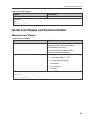
Serial Line Output and Communication
Measurement Output
Measurement Output Format
Serial Line Communication
Analog Output
Calibration and Adjustment
Other Commands
49
49
53
55
59
63
65
8 MI70 Hand-Held Indicator
MI70 Indicator Overview
Indicator Keypad
Basic Display
Graphical Display
Main Menu
Installing and Recharging the MI70 Batteries
Connecting MI70 to Service Port
Holding and Saving the Display
Recording Data
Starting and Stopping the Recording
Viewing Recorded Data
Deleting Recorded Files
Comparing Readings with MM70 Probe
Changing the Rechargeable Battery Pack
67
67
67
68
69
69
69
70
70
71
71
72
73
73
74
9 Calibration and Adjustment
H2 Calibration and Adjustment
Taking DGA Sample and Saving Current H2 Reading
Entering DGA H2 Reading to Transmitter
RS & T Calibration and Adjustment
76
76
76
78
79
10 Troubleshooting
Error States
Changing Bleed Screw
Technical Support
80
80
82
83
11 Technical Data
Spare Parts and Accessories
Dimensions
Wiring Diagrams
Recycling
84
87
88
89
91
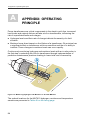
A Appendix: Operating Principle
Method Used for Measuring Moisture in Oil
Transformer Oil
94
95
95
B Appendix: Modbus Reference
97
4
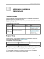
Function Codes
Register Map
Data Encoding
32-Bit Floating Point Format
16-Bit Integer Format
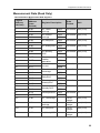
Measurement Data (Read Only)
Status Registers
Device Identification Objects
Exception Responses
C Appendix: Moisture PPM Calculation for Transformer Oils
Calculation Model with Average Coefficients
Calculation Model with Oil Specific Coefficients
97
97
98
98
98
99
101
102
102
103
103
103
5
1 Safety
1
SAFETY
Vaisala Moisture, Hydrogen and Temperature Transmitter MHT410 for
Transformer Oil delivered to you has been tested for safety and approved as
shipped from the factory. Note the following precautions:
Read the Quick Guide (including installation instructions)
carefully before installing the product.
Ground the product and verify outdoor installation grounding
periodically to minimize shock hazard.
Severe risk of death and of damage to transformer:
Pay attention to transmitter installation depth and possible
energized parts inside the power transformer to minimize electric
shock hazard and equipment damage.
Do not modify the unit. Improper modification can damage the
product or lead to malfunction.
Do not try to close the ball valve when the transmitter is fully
installed. The probe body goes through the valve into the oil flow,
and trying to close the valve will damage the probe body.
If you must close the ball valve while the transmitter is on the
valve, first open the small tightening nut and pull the probe body
out as far as possible. Then close the valve.
6
1 Safety
To avoid damage to the installation valve of the transformer, do
not step on the transmitter when the transmitter is installed.
Follow the safety regulations related to the application and
installation site.
ESD Protection
Electrostatic Discharge (ESD) can cause immediate or latent damage to
electronic circuits. Vaisala products are adequately protected against ESD for
their intended use. However, it is possible to damage the product by delivering
an electrostatic discharge when touching, removing or inserting any objects
inside the equipment housing.
Use appropriate ESD protective equipment when handling the wiring and
connectors under the front cover. Do not touch any parts under the circuit board
cover.
7
2 General Information
2
GENERAL INFORMATION
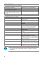
About This Document
Table 1 Document Version History
Document Code
Date
Description
M211737EN-A
June 2015
This document. The first version.
Table 2 Related Manuals
Document
Code
Description
M211736EN
Vaisala Moisture, Hydrogen and Temperature Transmitter MHT410 for
Transformer Oil Quick Guide
M211784EN
Loop-Powered Display 242003 for MHT410 Technical Note
Documentation Conventions
Warning alerts you to a serious hazard. If you do not read and
follow instructions very carefully at this point, there is a risk of
injury or even death.
Caution warns you of a potential hazard. If you do not read and
follow instructions carefully at this point, the product could be
damaged or important data could be lost.
Note highlights important information on using the product.
8
2 General Information
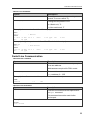
Regulatory Compliances
Up-to-date declarations of conformity are available at request from Vaisala
(www.vaisala.com).
This product is in compliance with the following EU directives:
n
n
EMC Directive
RoHS Directive
Conformity is shown by compliance to standards listed in Technical Data on
page 84.
Trademarks
HUMICAP® is a registered trademark of Vaisala Oyj.
All other trademarks are the property of their respective owners.
Software License
This product contains software developed by Vaisala. Use of the software is
governed by license terms and conditions included in the applicable supply
contract or, in the absence of separate license terms and conditions, by the
General License Conditions of Vaisala Group.
Warranty
Visit our Internet pages for more information and our standard warranty terms
and conditions: www.vaisala.com/warranty.
Please observe that any such warranty may not be valid in case of damage due
to normal wear and tear, exceptional operating conditions, negligent handling or
installation, or unauthorized modifications. Please see the applicable supply
contract or Conditions of Sale for details of the warranty for each product.
9
3 Product Overview
3
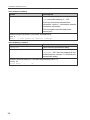
PRODUCT OVERVIEW
Vaisala Moisture, Hydrogen and Temperature Transmitter MHT410 for
Transformer Oil is designed for online monitoring of insulating oil in power
transformers. The transmitter provides an accurate real-time measurement result
of moisture, hydrogen and temperature measured in oil, enabling reliable
conclusions on the transformer's condition without delay.
The transmitter provides digital and analog outputs of all the measured
parameters.
10
3 Product Overview
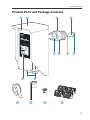
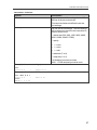
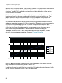
Product Parts and Package Contents
1
2
3
5
9
4
6
7
8
10
5 mm
+
3 mm
11
12
13
14
11
3 Product Overview
No.
Item
Electronics housing.
1
=
2
=
Weather shield
3
=
Bleed screw
4
=
Probe body
5
=
Small tightening nut, used to adjust and fix the depth of the transmitter in the
valve.
The front cover is additionally connected to the housing with a grounding wire.
You can move the tightening nut and the mounting nut along the probe body.
6
=
Mounting nut, used to fasten the transmitter in the ball valve.
You can move the tightening nut and the mounting nut along the probe body.
7
=
Hydrogen sensor
8
=
Moisture and temperature sensors under the filter
9
=
10
=
Product label
Lead-throughs (2 pcs) with a minimum of one cable gland (size M20x1.5) or
conduit fitting.
Unused lead-throughs are plugged.
Installation Kit:
11
=
PTFE tape roll
12
=
Allen keys (3 mm and 5 mm)
13
=
Extra bleed screw and sealing ring
14
=
Extra terminal blocks (4 x 4 screw terminals)
For the dimensions of the transmitter, see Dimensions on page 88.
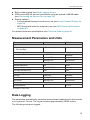
Main Features
n
n
n
n
n
n
12
Reliable online measurement of transformer oil for the following parameters:
o Moisture: relative saturation (%RS), water activity, and water content (ppm)
o Hydrogen concentration (ppm in oil)
o Temperature (°C and °F)
No need to take oil samples for measurement
Installable and retro-fittable on a ball valve (1.5" NPT thread)
Low maintenance requirements due to excellent long term stability
Outputs
o Digital: Modbus and Vaisala industrial protocol over RS-485
o Analog: three channels with scalable current output
Status indication LEDs in the front panel (see Status LEDs on page 14)
3 Product Overview
Built-in data logging (see Data Logging below)
USB connectivity for service connections using an optional USB M8 cable
(see Connecting via Service Port on page 39)
Display options:
o Loop-powered display for continuous use (see Loop-Powered Display on
page 30)
o MI70 hand-held meter for temporary use (see MI70 Hand-Held Indicator
on page 67)
n
n
n
For detailed technical specifications, see Technical Data on page 84.
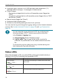
Measurement Parameters and Units
Parameter
Abbreviation
Unit
H2 concentration in oil
n 1 h average
H2
ppm
Rate of change of H2 concentration *
In a day
Daily ROC
ppm/day
In a week
Weekly ROC
ppm/week
In a month
Monthly ROC
ppm/month
Relative saturation
Water activity
RS
%RS
aw (=RS/100)
(no unit)
H2O concentration in oil
H2O
ppm
Rate of change of moisture in oil *
In a day
Daily ROC
ppm/day
In a week
Weekly ROC
ppm/week
In a month
Monthly ROC
ppm/month
T
°C or °F
n
24 h average *
Moisture in oil
Temperature
Oil temperature
* Not available on analog output.
Data Logging
The transmitter automatically saves the measurement readings and other events
in a log every 12 hours. The log can contain approximately 32000 entries.
The following events are logged:
13
3 Product Overview
Hydrogen (ppm), moisture in oil (%RS and ppm) and temperature (°C)
readings as 24 h averages, 1 h averages or instant values
Power outages
o Short power outages that do not turn off transmitter power (flagged as
"UPS")
o Long power outages that turn off transmitter power (flagged first as "UPS"
and then as "Reset")
Manual resets (flagged as "Reset")
Uptime and total operating time
Occasions of exceeding hydrogen alarm level (optional)
n
n
n
n
n
You can view the log and change the logging settings via the Vaisala industrial
protocol. See Vaisala Industrial Protocol on page 38 and Log Command on
page 50.
You can save the log as a file from PuTTY by configuring the
following settings in PuTTY before opening the connection:
In the Session > Logging view:
n
n
Session logging: Select "Printable output".
Log file name: Type a name for the log file (use the file
extension .txt) and browse for the location where to save the
file.
To prevent the log from getting very long, consider saving and
then clearing the log every few years.
Status LEDs
When the transmitter is ON, one of the LEDs is always illuminated (steady or
blinking). If no LED is illuminated, the transmitter is OFF.
LED Color and Text
Description
Green, blinking:
Transmitter is preparing H2 measurement after startup or reset.
Wait...
Green, steady:
Transmitter is measuring.
OK
Red, blinking:
Alarm
14
H2 concentration is above the alarm limit.
3 Product Overview
LED Color and Text
Description
Red, steady:
Transmitter is in error state.
Error
15
4 Installation
4
INSTALLATION
The installation instructions in this section are the same as in the
MHT410 Quick Guide.
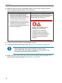
Before you install the transmitter:
16
n
Go through the check list in section Planning the Installation
on the facing page.
n
Read the Quick Guide (including installation instructions)
carefully.
n
Make sure there is no negative pressure in the transformer. If
there is negative pressure when you open the bleed screw
during installation, air will be sucked into the transformer oil
tank.
n
Do not open the ball valve on the transformer until you are
instructed to do so in this guide.
n
Make sure the bleed screw on the mounting nut is closed.
4 Installation
Mechanical installation:
n
n
n
n
n
n
Large wrench (50 mm)
Medium wrench (36 mm)
Allen key (3 mm, provided)
PTFE tape (provided)
Gloves
Bucket and cloth
Electrical installation (if cable is not pre-wired):
n
n
n
n
n
Allen key (5 mm, provided)
2 medium wrenches (24 mm)
Flat head screwdriver (2.5 mm)
Wire-cutting pliers
Suitable cable. You can order the following cables from
Vaisala:
o 5 m shielded PUR cable (order code: CBL210392-5MSP)
o 10 m shielded PUR cable (order code: CBL21039210MSP)
Planning the Installation
n
n
Choose the installation location on the transformer. See Recommended
Installation Locations on page 19.
Make sure the installation valve is appropriate (female 1.5" NPT thread).
17
4 Installation
n
Measure and record the installation depth in the chosen valve to achieve
optimal measurement position for the sensors.
Valve in Radiator Pipe
o
Moisture and temperature sensors
are directly in the oil flow. This is
because water molecule diffusion rate
in oil is slow, and therefore moisture
must be measured in moving oil.
o
Hydrogen sensor is in the valve area.
This is because the hydrogen sensor
needs an accurate temperature
control, and therefore hydrogen must
be measured in still oil.
Valve in Transformer Wall
Tip of the probe is level with transformer
inner wall. No part of the probe must enter
the transformer chamber. All sensors
remain within the valve area.
Severe risk of death and of
damage to transformer:
Pay attention to transmitter
installation depth and possible
energized parts inside the power
transformer to minimize electric
shock hazard and equipment
damage.
n
n
Choose the output signals: analog and/or digital.
Choose the electrical wiring option. See Wiring Diagrams on page 89.
If the transmitter was ordered with the Vaisala cable
CBL210392-5M, the cable is already pre-connected to the
transmitter according to Wiring Option 1.
n
18
Make sure you have all the required tools for installing the transmitter. The
required tools are presented in Installation on page 16.
4 Installation
Recommended Installation Locations
The probe must always be installed in a valve.
Recommendation
Description
Straight section in the radiator’s outlet pipe.
This is the best location for the transmitter.
Recommended
The oil is measured in flow, which makes the oil sample
representative and instant. This is essential especially for correct
oil moisture measurement.
Compared to the radiator inlet pipe, oil in the outlet pipe is cooled,
preventing unnecessary heating of the sensors and the
transmitter.
Side of the oil tank, high enough from the bottom to enable proper
oil movement. An instrumentation valve is recommended with
appropriate threads.
Possible alternative
This is a typical valve that is meant for oil analysis. Moisture
response time is moderate depending on the oil volume and
transmitter installation.
Severe risk of death and of damage to transformer:
Pay attention to transmitter installation depth and possible
energized parts inside the power transformer to minimize
electric shock hazard and equipment damage.
Drain valve of the oil tank.
Not recommended
The moisture response is poor due to static oil flow. There is also
risk of separated water (leading to wrong results) and oil sludge
(risk of sensor contamination and clogged filters).
19
4 Installation
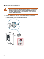
Mechanical Installation
Before you install the transmitter, make sure there is no negative
pressure in the transformer. If there is negative pressure when
you open the bleed screw during installation, air will be sucked
into the transformer oil tank.
1. Remove the protective cap with sorbent packet from the mounting nut.
In case of rain, do not let any water fall on the filter.
20
4 Installation
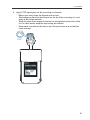
2. Apply PTFE tape tightly on the mounting nut threads.
o
o
o
o
Before you start, clean the threads with a cloth.
Start wrapping from the third thread on the tip of the mounting nut, and
apply a few loops inwards.
Wrap the tape in the opposite direction to the tightening direction of the
nut. In other words, wrap the tape along the threads.
Wrap each loop about half way on top of the previous loop so that the
loops overlap.
PTFE
21
4 Installation
3. Fasten the mounting nut on the ball valve with your hand. Then tighten the
mounting nut with a wrench. Leave the bleed screw directly on top of the
nut.
Always make sure the bleed screw is closed before you turn
the mounting nut with a wrench.
22
4 Installation
4. With a 3 mm Allen key, loosen the bleed screw. Place a bucket under the
mounting nut.
OPEN
max. 3 × 360°
5.
a. Start opening the valve very carefully to let air out through the bleed
screw.
If you open the valve too quickly, the air inside the
mounting nut will be sucked into the transformer instead.
b. When oil flows out, close the bleed screw. Clean the area with a cloth
and open the ball valve fully.
SLOW
CLOSE
23
4 Installation
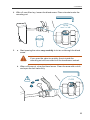
6. If needed, continue tightening the mounting nut until the connection is oiltight.
24
4 Installation
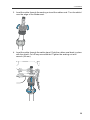
7. Push the probe to correct depth according to installation location.
Valve in Radiator Pipe
o
Moisture and temperature sensors
are directly in the oil flow.
o
Hydrogen sensor is in the valve area.
Valve in Transformer Wall
Tip of the probe is level with transformer
inner wall. No part of the probe must
enter the transformer chamber. All
sensors remain within the valve area.
Severe risk of death and of
damage to transformer:
Pay attention to transmitter
installation depth and possible
energized parts inside the power
transformer to minimize electric
shock hazard and equipment
damage.
25
4 Installation
26
4 Installation
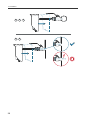
8. Tighten the small tightening nut with a wrench until it the probe is securely
fastened.
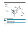
Electrical Installation
If the transmitter was ordered with the Vaisala cable CBL2103925M, the cable is already pre-connected to the transmitter
according to Wiring Option 1.
To connect the cable to the transmitter:
1. Open the electronics housing with a 5 mm Allen key to access the screw
terminals.
27
4 Installation
SERIAL COMMA
Device informa NDS
tion
?
List of errors
ERRS
List of comman
ds HELP
See manual
for further
commands.
www.vaisala.co
m/MHT410
RS-485
TERMINATION
SERVICE
PORT
19200 b/s,
8, n, 1
RS-485
Modbus default
address: 240
OFF
ON
SHLD
RS
POWER
GND
D–
8
D+
7
SHLD
6
+ Vs
5
– Vs
+ CH2
– CH2
4
+ CH1
3
TS
– CH1
NALOG OUTPU
9 10 11
12 13 14
15 16
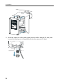
2. Hold the upper nut of the cable gland in place with a wrench (24 mm), and
loosen the sealing nut of the gland with another wrench (24 mm).
28
4 Installation
3. Lead the cable through the sealing nut and the rubber seal. Turn the shield
over the edge of the rubber seal.
4. Lead the cable through the cable gland. Push the rubber seal back in place
with the shield. Cut off any excess shield. Tighten the sealing nut with
wrench (24 mm).
29
4 Installation
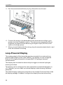
5. Pull the screw terminal blocks (2 pcs) off from the circuit board.
10
11
12
POW
13
14
+ Vs
9
15
ER
– Vs
8
D+
7
SHLD
6
SHLD
RS
GND
D–
5
RS
Mod -485
bu
addr s defaul
ess:
t
240
OFF
ON
PUT
S
+ CH1
4
OUT
– CH1
3
+ CH2
2
LOG
– CH2
1
ANA
– CH3
+ CH3
R
TER S-485
MIN
ATIO
N
16
6. Connect the wiring to the detachable screw terminals according to your
chosen electrical installation option. The options are presented in Wiring
Diagrams on page 89. Note that wiring for digital output (RS-485) is the
same in all wiring options.
7. When you are finished with the wiring, plug the screw terminals back in and
close the electronics housing.
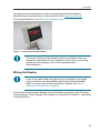
Loop-Powered Display
The analog outputs of the transmitter can be connected to an external looppowered LED display (order code 242003). The display is a pre-configured
Nokeval 302 display intended for Vaisala MHT410 hydrogen channel
measurements.
The display also includes two alarm relays to trigger an external hydrogen
warning and alarm.
This display can be configured for other parameters (moisture/temperature in
oil). If needed, you can install up to three displays, each showing a different
parameter.
The default display settings are presented in the Vaisala Technical Note inside
the display package. If needed, configure the display functions and scaling
30
4 Installation
according to the manufacturer's instructions delivered with the display.
Manufacturer’s documentation is also available from www.nokeval.com.
For wiring instructions, see Wiring the Display below.
Figure 1 Loop-Powered Display 242003
The loop resistance of the display must be included in the loop
resistance calculation for the complete current loop. For the loop
resistance of the display, refer to the manufacturer’s
documentation.
Wiring the Display
If one of the cable lead-throughs on your transmitter is plugged
and you want to use that lead-through for the Nokeval display
cable, you can order a cable gland from Vaisala. See Spare
Parts and Accessories on page 87.
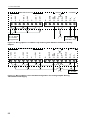
Connect the loop-powered display to the transmitter as shown in the following
wiring diagram. In the diagram, the display is connected to Channel 1 according
to Wiring Option 1.
31
+CH3
-CH3
SHLD
+CH2
-CH2
SHLD
+CH1
-CH1
4 Installation
1
2
3
4
5
6
7
8
Nokeval Display
1 mA+
2 mA-
A1(hi)
A2(hihi)
3
7
6
5
4
4...20 mA
RL = 0...500 Ω
15...30 VDC,
power supply
for analog channel
and display
Figure 2 Example of Nokeval Display Wired to Channel 1. Transmitter Wiring According to
Wiring Option 1.
All the Wiring Options (1, 2, 3, and 4) have the same principle for
connecting the display:
n
n
Wire from port 1 of the display connects to the minus port of
the transmitter's analog output channel (for example, to "CH1").
Wire from port 2 of the display connects to where the minus
port wire of the analog output channel would have connected
without the display.
For wiring alternatives, see Wiring Diagrams on page 89.
32
4 Installation
Checklist After Installation
After the installation, check the following indicators to make sure the installation
was successful:
n
n
n
No oil is leaking from the transformer and the transmitter.
The indicator LED blinks green for some minutes and then becomes steady.
o Steady green indicates that the H 2 level is below alarm limit.
o Blinking red indicates that the H 2 level is above alarm limit.
After the initial stabilization period (approx. 24 h power on), the reading is
correct.
Oil Fittings Check After Installation
After the first month of continuous use, all oil fittings should be checked for leaks.
An annual check thereafter is recommended.
Removing the Transmitter
To disconnect wiring:
n
n
n
Allen key (5 mm, provided)
2 medium wrenches (24 mm)
Flat head screwdriver (2.5 mm)
To remove transmitter:
n
n
n
n
Large wrench (50 mm)
Medium wrench (36 mm)
Gloves
Bucket and cloth
Do not try to close the ball valve when the transmitter is fully
installed. The probe body goes through the valve into the oil flow,
and trying to close the valve will damage the probe body.
1. If needed, disconnect the wiring:
a. Open the front cover and disconnect the wires from the detachable
screw terminals.
33
4 Installation
b. Hold the upper nut of the cable gland in place with a wrench (24 mm),
and loosen the sealing nut of the gland with another wrench (24 mm).
c. Pull the cable out of the cable gland.
d. Re-attach the cable gland in its place.
2. Put a bucket under the ball valve to catch any oil falling from the valve.
3. Loosen the small tightening nut with a wrench.
To keep the larger mounting nut from opening, hold it in
place with a wrench as you are opening the smaller
tightening nut.
4. Pull the transmitter outward so that the probe body is out of the ball valve.
5. Close the ball valve.
6. Open the mounting nut with a wrench and pull the transmitter out. Use the
cloth to clean up any spills.
Always make sure the bleed screw is closed before you turn the
mounting nut with a wrench.
34
5 Analog Output
5
ANALOG OUTPUT
There are three analog output channels available for H 2, moisture in oil, and
temperature using 4... 20 mA current outputs.
The parameter for each output is configured at the factory according to order. If
needed, you can change the parameters using Vaisala Industrial Protocol. For
instructions, see table Asel Command on page 61.
Table 3 Analog Output Values in Different Transmitter Statuses
Transmitter Status
Analog Output Value
Normal
4...20 mA
Error
3.5 mA (default)
Measurement not ready
3.0 mA
Analog Output Overrange Behavior
If the measured hydrogen, moisture and temperature levels go below or above
their scaled range, the analog output is clipped at the low (4 mA) or high (20 mA)
end of the output range. This means the analog output will not indicate
measurement readings that are outside the scaled ranges.
If needed, you can allow the analog outputs to extend 10 % of the range over
20 mA using the aover command via Vaisala Industrial Protocol (see Table 29
on page 60). With this extension, the allowed range for analog outputs is
4 mA ... 21.6 mA. The aover command does not affect the scaling of the outputs.
You can also change the scaling of the outputs for each channel using the asel
command. See Table 30 on page 61.
35
5 Analog Output
CURRENT
OUTPUT
21.6 mA
20 mA
4 mA
MEASURED
VALUE
High end High end
of scale of scale
+10 %
Analog output
of scale
Analog output extended at high end of range
Low end
of scale
Figure 3 Analog Output Overrange Behavior
36
6 Modbus
6
MODBUS
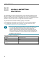
Overview of Modbus Protocol Support
MHT410 can be accessed using the Modbus serial communication protocol. The
supported Modbus variant is Modbus RTU (Serial Modbus) over RS-485
interface.
The supported Modbus functions and registers are described in
Appendix: Modbus Reference on page 97.
By default, Modbus is enabled on MHT410. The pre-configured default software
settings are presented in the following table.
Description
Default value
Serial bit rate
19200
Parity
N
Number of data bits
8 (read-only)
Number of stop bits
1
Modbus device address
240
You can change the Modbus settings using Vaisala Industrial Protocol. For
instructions, see Serial Line Output and Communication on page 49.
The minimum time between requests from Modbus is 1 second.
37
7 Vaisala Industrial Protocol
7
VAISALA INDUSTRIAL
PROTOCOL
The transmitter provides an implementation of the Vaisala Industrial Protocol
that can be used for service and configuration use, or for interfacing with the
system to which the transmitter is integrated. The protocol is a plaintext protocol
suitable for use both by human operators and automated systems.
You can access the Vaisala Industrial Protocol in two ways:
For permanent connection, use the RS-485 line of the screw terminals.
For temporary connection with a computer, use the service port. See
Connecting via Service Port on the facing page.
n
n
You can use Vaisala Industrial Protocol via the RS-485 line of
the screw terminals and the service port at the same time.
However, the transmitter responds to the commands one at a
time from either line, which may result in delayed responses if a
command is entered from one line while another command is in
progress on the other line.
Table 4 Default Serial Interface Settings
Property
Description/Value
Baud rate
19200
Parity
None
Data bits
8
Stop bits
1
Flow control
None
38
7 Vaisala Industrial Protocol
Connecting via Service Port
n
Vaisala USB service cable (219690)
n
Computer with:
o Windows operating system
o Free USB port
o Terminal application (e.g. PuTTy available from
www.vaisala.com/software)
o Driver for Vaisala USB service cable installed (available on
the cable installation media and at
www.vaisala.com/software)
You can connect to the transmitter on a computer using the service port located
under the transmitter cover. For a list of commands, see Serial Commands on
page 42.
If you have not used the Vaisala USB cable before, install the driver before
attempting to use the cable. See Installing the Driver for the USB Service Cable
below for detailed instructions.
For more information on using a terminal application, see Terminal Application
Settings on the next page.
Connecting USB Cable
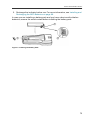
To connect the USB service cable to the service port:
1. Make sure the USB cable is connected to your computer.
2. Open the screws on the transmitter cover, and open the cover.
3. Connect the USB service cable to the service port connector on the
transmitter.
4. Configure the terminal application settings as instructed in Terminal
Application Settings on the next page.
Installing the Driver for the USB Service Cable
Before taking the USB service cable into use for the first time, you must install
the provided USB driver on your computer (requires Windows). When installing
the driver, you must accept any security prompts that may appear.
1. Check that the USB service cable is not connected. Disconnect the cable if
you have already connected it.
2. Insert the media that came with the cable, or download the latest driver from
www.vaisala.com/software.
39
7 Vaisala Industrial Protocol
3. Run the USB driver installation program (setup.exe), and accept the
installation defaults. The installation of the driver may take several minutes.
4. After the driver has been installed, connect the USB service cable to a USB
port on your computer. Windows will detect the new device, and use the
driver automatically.
5. The installation has reserved a COM port for the cable. Verify the port
number, and the status of the cable, using the Vaisala USB Instrument
Finder program that has been installed in the Windows Start menu.
Windows will recognize each individual service cable as a different device, and
reserve a new COM port. Remember to use the correct port in the settings of
your terminal program.
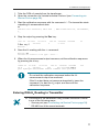
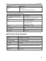
Terminal Application Settings
The steps below describe how to connect to the transmitter using the PuTTY
terminal application for Windows (available for download at
www.vaisala.com/software) and a USB service cable:
1. Make sure the USB service cable is connected to your PC and the service
port of the transmitter.
2. Start the PuTTY application.
40
7 Vaisala Industrial Protocol
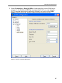
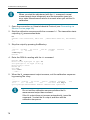
3. Select Connection > Serial & USB and check that the correct COM port is
selected in the Serial or USB line to connect to field. If you are using the
PuTTY terminal application supplied by Vaisala, you can click the USB
Finder button to open the Vaisala USB Instrument Finder program.
Figure 4 PuTTY Terminal Application
41
7 Vaisala Industrial Protocol
4. Check that the other serial settings are correct, and change if necessary.
Table 5 Service Port Serial Interface Settings
Property
Value
Baud rate
19200
Parity
None
Data bits
8
Stop bits
1
Flow control
None
5. Select Terminal. Use the following settings:
o
Local Echo: "Force on". This setting ensures that your typing is shown on
the session window.
o
Send line ends with line feeds (CR+LF): Selected. This setting ensures
that all text lines remain visible on the session window.
6. Click the Open button to open the connection window and start using the
serial line.
If PuTTY is unable to open the serial port you selected, it will
show you an error message instead. If this happens, restart
PuTTY and check the settings.
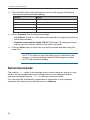
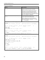
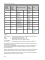
Serial Commands
The notation <cr> refers to the carriage return control character, which you can
send in a terminal application by pressing enter on your keyboard. Before
entering commands, send a <cr> to clear the command buffer.
You can enter the commands in uppercase or lowercase. In the command
examples, the keyboard input by the user is in bold type.
42
7 Vaisala Industrial Protocol
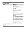
Command
Description
Page
Device information and status
?
Show device information.
44
??
Show device information (will respond in poll mode).
44
alarm
Show or set H2 alarm level.
45
errlog
Show error log records.
46
errs
Show active errors.
47
help
Show list of serial commands.
48
system
Show firmware information.
48
time
Show transmitter uptime (time since last reset).
48
vers
Show the software version information.
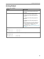
Serial line output and communication
addr
Show or set device address.
close
Close connection to device in POLL mode.
49
55
55
This command cannot be used via the Service Port.
form
Set output format of measurement messages.
53
log
Show measurement log reconds.
50
intv
Set measurement output interval.
Open connection to device in POLL mode.
49
open
56
This command cannot be used via the Service Port.
r
Start continuous output of measurement messages.
52
sdelay
Show or set serial line transmission delay.
56
send
Output one measurement message.
Set serial line settings for the RS-485 line of the screw
terminals. Default is 19200 N 8 1.
52
seri
57
This command does not affect the service port settings.
smode
Set serial line operation mode for the RS-485 line of the
screw terminals.
58
This command does not affect the service port settings. The
service port is always in stop mode.
unit
Set temperature unit to metric (°C) or non-metric (°F).
55
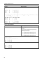
Analog output
aerr
Show or set error level for analog output.
59
aover
Enable or disable analog output 10 % over range.
60
asel
Show or set analog output parameters and scaling.
61
atest
Test analog outputs by forcing them to a given value.
62
43
7 Vaisala Industrial Protocol
Command
Description
Page
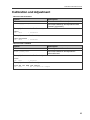
Calibration and adjustment
cdate
Show or set adjustment date.
63
ctext
Show or set adjustment information text.
63
h2
Start or continue hydrogen calibration and adjustment
sequence.
64
filt
frestore
Show or set measurement filtering.
65
Restore factory settings. Clears all user settings, factory
calibration remains.
66
reset
Reset the device.
66
Other commands
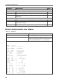
Device Information and Status
Table 6 ? Command
Syntax
?<cr>
Description
??<cr>
Show listing of device information when
device is in poll mode and connection has not
been opened using the open command.
Show listing of device information.
Example:
?
MHT410 / 0.1.20
Serial number :
Batch number
:
Sensor number :
Sensor model
:
Order code
:
Cal. date
:
Cal. info
:
Uptime
:
Total time
:
Serial mode
:
Baud P D S
:
Output interval:
Serial delay
:
Address
:
Filter
:
Ch1 output
:
Ch2 output
:
Ch3 output
:
Ch1 RS
lo
:
Ch1 RS
hi
:
Ch2 T
lo
:
Ch2 T
hi
:
Ch3 H2
lo
:
Ch3 H2
hi
:
44
A1234567
A1234567
A1234567
Humicap L2
A123456789
20150414
Vaisala
0000d 04:04:41
0000d 04:04:41
STOP
19200 N 8 1
1 S
25
0
1.000
4 ... 20 mA
4 ... 20 mA
4 ... 20 mA
0.00 %
100.00 %
-40.00 'C
100.00 'C
0.00 ppm
5000.00 ppm
7 Vaisala Industrial Protocol
Table 7 Alarm Command
Syntax
alarm<cr>
Description
Check the status and setpoint (ppm) of the
hydrogen alarm.
The alarm is activated when the 1-hour
average for hydrogen exceeds the setpoint.
alarm [on | off] [setpoint]<cr>
Set the hydrogen alarm status.
on = Alarm indication is on.
off = Alarm indication is off.
setpoint = Hydrogen level above which
the alarm is activated.
Example (check the hydrogen alarm status, alarm is off):
alarm
Alarm display :
Setpoint (ppm) :
OFF
300
?
?
Example (enable the hydrogen alarm and set the alarm limit to 200 ppm hydrogen):
alarm on 200
Alarm display :
Setpoint (ppm) :
ON
200
45
7 Vaisala Industrial Protocol
Table 8 Errlog Command
Syntax
errlog print<cr>
Description
Show the error log with max. 25 last log
entries.
The error log stores the error status each
time the status changes.
You can save the error log as a file
from PuTTY by configuring the
following settings in PuTTY before
opening the connection:
In the Session > Logging window:
errlog print [n] [i]<cr>
n
Session logging: Select
"Printable output".
n
Log file name: Type a name for
the log file (use extension .txt) and
browse for the location where to
save the file.
Show the error log with a chosen number of
entries.
n = Number of entries to show (max. 9 999).
i = Optional: Index number of the first
shown entry. If this parameter is not used,
the list will show the last n number of entries.
errlog save<cr>
errlog clear<cr>
Save the current error status for
troubleshooting purposes.
Remove all entries from the error log.
Clearing the error log may make
troubleshooting more difficult later if a
problem occurs.
46
7 Vaisala Industrial Protocol
Syntax
Description
Example (show error log):
errlog print
index RecNum
1
1
2
2
3
3
4
4
5
5
6
6
7
7
...
Reset
1
2
2
2
2
2
3
0
0
0
0
0
0
0
Days Time
00:00
00:37
00:37
00:38
01:10
01:15
00:36
ERRS
H2err
0
0
0
0
0
0
0
ERRS
8
0
8
0
8
H2err
0
0
0
0
0
8
8
0
8
0
8
2
Example (show the last 5 entries):
errlog print 5
index RecNum
27
27
28
28
29
29
30
30
31
31
Reset
19
19
19
19
19
Days Time
0 04:59
0 05:11
0 05:18
0 05:21
0 05:22
Example (save the current error status):
errlog save
New value stored.
Example (remove all entries from the error log):
errlog clear
Erase all Error Log data? (Y/N) y
Erasing...
Error Log cleared.
Table 9 Errs Command
Syntax
errs<cr>
Description
Show currently active errors.
The possible errors and their remedies are
listed in Possible Error Messages via Vaisala
Industrial Protocol on page 80.
Example (no errors active):
errs
No errors
47
7 Vaisala Industrial Protocol
Table 10 Help Command
Syntax
help<cr>
Description
Show a list of available commands.
Example:
help
Stop mode commands:
ADDR
AERR
ALARM
CTEXT ERRLOG ERRS
INTV
LOG
R
SYSTEM TIME
UNIT
AOVER
FILT
RESET
VERS
ASEL
FORM
SDELAY
?
ATEST CDATE
FRESTORE H2
SEND
SERI
CLOSE
HELP
SMODE
Poll mode commands:
OPEN
SEND
??
Table 11 System Command
Syntax
system<cr>
Description
Show firmware information.
Example:
system
Device Name
Copyright
reserved.
SW Name
SW date
SW version
OS version
: MHT410
: Copyright (c) Vaisala Oyj 2015. All rights
:
:
:
:
MHP410
2015-03-31
0.1.20
TSF 1.0
Table 12 Time Command
Syntax
time [mode]<cr>
Description
Show transmitter uptime (time since last
reset). Default output: hh:mm:ss.
mode = alternative output option (optional)
n
1 = include days (dddd hh:mm:ss)
n
2 = include decimals of seconds
(hh:mm:ss.sss)
n
3 = include days and decimals of seconds
n
4 = include total operating time
Example (show transmitter uptime in hh:mm:ss):
time
Uptime
: 00:50:04
Example (show transmitter uptime with days):
time 1
Uptime
48
: 0002d 01:50:39
7 Vaisala Industrial Protocol
Table 13 Vers Command
Syntax
vers<cr>
Description
Show the software version information.
Example:
vers
MHT410 / 0.1.20
Serial Line Output and Communication
Measurement Output
Table 14 Intv Command
Syntax
intv<cr>
Description
Show the output interval of the automatically
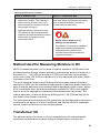
repeating measurement messages (r
command and run mode).
This command has no effect on the
operation of the analog output.
Set the output interval.
intv [iii uuu]<cr>
iii = interval, range 1 ... 255
uuu = unit for interval setting:
n
s = seconds
n
min = minutes
n
h = hours
Example (set the output interval to 1 second):
intv 1 s
Output interval:
1 S
49
7 Vaisala Industrial Protocol
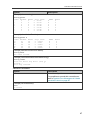
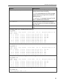
Table 15 Log Command
Syntax
log print<cr>
Description
Show the measurement log with max.100
last log entries.
You can save the log as a file from
PuTTY by configuring the following
settings in PuTTY before opening the
connection:
In the Session > Logging window:
n
Session logging: Select
"Printable output".
n
Log file name: Type a name for
the log file (use extension .txt) and
browse for the location where to
save the file.
To prevent the log from getting very
long, consider saving and then
clearing the log every few years.
log print [n] [i]<cr>
Show the measurement log with a chosen
number of entries.
n = Number of entries to show (max.
32767).
i = Optional: Index number of the first
shown entry. If this parameter is not used,
the list will show the last n number of entries.
log alarm [on|off]<cr>
Enable or disable storing a log item when
the H2 concentration (1 hour average)
exceeds the alarm level. Logging continues
once an hour until the H2 level returns below
the alarm limit or until alarm logging is
disabled. The log entries contain the
additional tag "H2alarm".
You set the H2 alarm level using the alarm
command (see Table 7 on page 45).
50
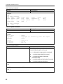
7 Vaisala Industrial Protocol
Syntax
log filt [on|off]<cr>
Description
Enable or disable the filtering of
measurement values in the log.
on = For each parameter, the 24 h average
value is stored. The log entries contain the
additional tag "F".
off = For H2, 1 h average is stored. For RS
and T, instant values are stored.
log save<cr>
log clear<cr>
Save the current measurement values in
the log. The log entry contains the additional
tag "12h Tst".
Remove all entries from the measurement
log.
Example (show up to 100 last entries in the log):
log print
index Reset Days Uptime
Total Time
(ppm) Flags
1 2 0 00:08 0 00:17 10.000 13.900
2 2 0 00:13 0 00:22 10.000 13.900
3 5 0 00:37 0 00:59 10.000 13.900
4 5 0 00:52 0 01:14 10.000 13.900
5 7 0 12:00 0 13:14 10.000 13.900
6 11 0 00:04 0 13:18 10.000 13.900
7 11 0 00:12 0 13:26 10.000 12.900
8 12 0 00:03 0 13:29 10.000 13.900
RS (%)
45.406
45.467
45.303
45.278
45.887
45.495
45.716
45.531
H2O(ppm) Temp('C) H2
18.0 12h
18.0 12h
18.0 12h
18.0 12h
18.0 12h
18.0 12h
18.1 12h
18.2 12h
Tst
Tst
Tst
Tst
Example (show the last 5 entries):
log print 5
index Reset Days Uptime
Total Time
(ppm) Flags
4 5 0 00:52 0 01:14 10.000 13.900
5 7 0 12:00 0 13:14 10.000 13.900
6 11 0 00:04 0 13:18 10.000 13.900
7 11 0 00:12 0 13:26 10.000 12.900
8 12 0 00:03 0 13:29 10.000 13.900
RS (%)
45.278
45.887
45.495
45.716
45.531
H2O(ppm) Temp('C) H2
18.0
18.0
18.0
18.1
18.2
12h Tst
12h
12h
12h
12h
Example (show 5 entries starting from the 3rd entry):
log print 5 3
index Reset Days Uptime
Total Time
(ppm) Flags
3 5 0 00:37 0 00:59 10.000 13.900
4 5 0 00:52 0 01:14 10.000 13.900
5 7 0 12:00 0 13:14 10.000 13.900
6 11 0 00:04 0 13:18 10.000 13.900
7 11 0 00:12 0 13:26 10.000 12.900
RS (%)
45.303
45.278
45.887
45.495
45.716
H2O(ppm) Temp('C) H2
18.0
18.0
18.0
18.0
18.1
12h Tst
12h Tst
12h
12h
12h
Example (enable storing a log item when H2 alarm level is exceeded):
log alarm on
Alarm loggings: OFF -> ON
51
7 Vaisala Industrial Protocol
Syntax
Description
Example (disable filtering the measurement values in the log):
log filt off
24h rolling average filter: ON -> OFF
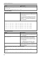
Table 16 R Command
Syntax
r<cr>
Description
Start the continuous outputting of
measurement values as an ASCII text string
to the serial line.
The probe keeps outputting measurement
messages at the interval that has been set
with the intv command until stopped with
the s command.
Example:
r
T= 45.1
T= 45.0
T= 45.0
T= 45.1
T= 45.1
T= 45.1
T= 45.1
T= 45.2
...
'C
'C
'C
'C
'C
'C
'C
'C
RS=
RS=
RS=
RS=
RS=
RS=
RS=
RS=
10.0
10.0
10.0
10.0
10.0
10.0
10.0
10.0
% % % % % % % % H2O=
H2O=
H2O=
H2O=
H2O=
H2O=
H2O=
H2O=
13.9
13.9
13.9
13.9
13.9
13.9
13.9
13.9
ppm
ppm
ppm
ppm
ppm
ppm
ppm
ppm
aw=
aw=
aw=
aw=
aw=
aw=
aw=
aw=
0.100 0.100 0.100 0.100 0.100 0.100 0.100 0.100 H2=
H2=
H2=
H2=
H2=
H2=
H2=
H2=
17
17
17
17
18
18
18
18
ppm
ppm
ppm
ppm
ppm
ppm
ppm
ppm
Table 17 Send Command
Syntax
send<cr>
send [aaa]<cr>
Description
Output a single measurement message.
The output uses the format defined with the
form command.
Output a single measurement message
when the transmitter is in poll mode and
connection has not been opened using the
open command.
aaa = Address of the transmitter, range
0 ... 255. Set with the addr command.
send ROC<cr>
Output the rate-of-change readings for H2
and H2O (daily, weekly and monthly ROC for
each parameter).
Example (transmitter in stop mode, no address needed):
send
T= 45.1 'C RS= 10.0 % H2O= 13.9 ppm aw= 0.100 H2= 17 ppm
Example (transmitter in poll mode, with address 10):
send 10
T= 45.1 'C RS= 10.0 % H2O= 13.9 ppm aw= 0.100 H2= 17 ppm
52
7 Vaisala Industrial Protocol
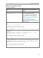
Measurement Output Format
Table 18 Form Command
Syntax
form<cr>
Description
form /<cr>
Reset measurement format to default.
Set a new measurement format.
Show the currently used measurement
format.
form [sss]<cr>
sss = String consisting of modifiers and
abbreviations for measured parameters.
See Table 19 on the next page and Table
20 on the next page.
Maximum length is 150 characters.
Maximum length may be shorter when text
strings are used.
Example (show currently used measurement format, default format shown here):
form
3.1 "T=" t " " U3 3.1 "RS=" rs " " U4 6.1 "H2O=" h2o " " U5 4.3 "aw="
aw " " 6.0 "H2=" h2 " " U5 \r \n
Output example (continuous output in RUN mode):
T= 45.0 'C RS= 10.0 %
H2=
18 ppm
H2O=
13.9 ppm
aw=
0.100
Example (change the order of the output to show H2 first, with Modulus-65536 checksum
at the end):
form 6.0 "H2=" h2 " " U5 3.1 "T=" t " " U3 3.1 "RS=" rs " " U4 6.1
"H2O=" h2o " " U5 4.3 "aw=" aw " " cs4 #r #n
OK
Output example (continuous output in RUN mode):
H2=
0E22
18 ppm
T= 45.0 'C RS= 10.0 %
H2O=
13.9 ppm
aw=
0.1
Example (show H2O in ppm without decimals, with start of text (ASCII character 002)
and end of text (003) ASCII codes, and without line feed and carriage return at the end):
form #002 6.0 "H2=" h2 " " U5 3.1 "T=" t " " U3 3.1 "RS=" rs " " U4
6.0 "H2O=" h2o " " U5 4.3 "aw=" aw " " #003
OK
Output example (continuous output in RUN mode):
H2=
aw=
18 ppm
0.100
T= 45.0 'C RS= 10.0 %
H2O=
14 ppm
53
7 Vaisala Industrial Protocol
Table 19 Output Parameters for Form Command
Relative saturation of water in oil, %RS
Measurement Parameter
Abbreviation in Form Command
rs
Water activity in oil, aw (range 0.0 ... 1.0)
aw
Water content in oil, ppm
h2o
Hydrogen content in oil, ppm. One hour
average.
h2
Oil temperature, °C or °F
t
Table 20 Modifiers for Form Command
Modifier
x.y
Description
#t
Tabulator.
#r
Carriage-return.
#n
Line feed.
""
String constant, length 1 ... 15 characters.
#xxx
ASCII code value (decimal) of a special
character; for example, #027 for ESC.
addr
Transmitter address (0 ... 254).
date
Uptime in days.
err
Error code, ASCII encoded hexadecimal
notation.
sn
Probe serial number.
time
Uptime (hh:mm:ss).
ux
Name of the measurement unit using x
number of characters (1 ... 9). For example,
u3 shows the name of the measurement unit
with three characters.
cs2
Modulus-256 checksum of message sent so
far, ASCII encoded hexadecimal notation.
cs4
Modulus-65536 checksum of message sent
so far, ASCII encoded hexadecimal notation.
csx
NMEA xor-checksum of message sent so
far, ASCII encoded hexadecimal notation.
Length modifier (number of digits and
decimal places).
You can also use the backslash character \ instead of the hash
character #.
54
7 Vaisala Industrial Protocol
Table 21 Unit Command
Syntax
unit<cr>
unit [m|n]<cr>
Description
Show the current temperature unit system
(metric °C on non-metric °F).
Change the temperature unit.
m = Metric unit, °C
n = Non-metric unit, °F
Example (show current unit and check the output):
unit
Units
: Metric
send
T= 45.0 'C RS= 10.0 %
H2O=
H2=
18 ppm
13.9 ppm
aw=
0.100
Example (change temperature unit from °C to °F and check the output):
unit n
Units
: Non metric
send
T=113.0 'F RS= 10.0 %
H2O=
H2=
18 ppm
13.9 ppm
aw=
0.100
Serial Line Communication
Table 22 Addr Command
Syntax
addr<cr>
Description
Show current device address and prompt
for a new address.
Addresses are required for POLL mode.
addr [aaa]<cr>
Set new device address.
aaa = address, 0 ... 255
Example (shows 0 as current address, enter 5 as the new address):
addr
Address : 0 ? 5
Table 23 Close Command
Syntax
close<cr>
Description
Close the connection that was opened with
the open command.
This command cannot be used via the
service port.
Example:
close
line closed
55
7 Vaisala Industrial Protocol
Table 24 Open Command
Syntax
open [aaa]
Description
Connect to a transmitter that is in poll mode.
aaa = transmitter address, 0 ... 255
If you do not know the address of the
transmitter, use the ?? command to view the
transmitter information.
This command cannot be used via the
service port.
Example (target transmitter in poll mode, with address 5):
open 5
MHT410
5 line opened for operator commands
Table 25 Sdelay Command
Syntax
sdelay<cr>
Description
Show serial line transmission delay.
Set a new serial line transmission delay.
sdelay [delay]<cr>
delay = 0 ... 255. Value corresponds to four
milliseconds (for example, 5 = 0.020 second
transmission delay)
Example (set serial delay to 0.1 seconds using the delay value 25):
sdelay 25
Serial delay
56
:
25
7 Vaisala Industrial Protocol
Table 26 Seri Command
Syntax
seri<cr>
Description
Show current serial line settings for the RS485 line of the screw terminals.
This command does not affect the service
port settings.
Set new serial line settings. The new settings
will be taken into use when the transmitter is
reset or powered up.
seri [p b d s] <cr>
b = baud rate (300, 600, 1200, 2400, 4800,
9600, 19200, 38400, 57600)
p = parity
n
n = none
n
e = even
n
o = odd
d = data bits (7 or 8)
s = stop bits (1 or 2)
For Modbus, baud rate must be
9600 ... 57600 and parity must be none.
Example (show current settings):
seri
Baud P D S
:
19200 N 8 1
Example (set baud rate to 9600, and reset the transmitter take the new baud rate in use):
seri 9600 N 8 1
Baud P D S
:
reset
MHT410 / 0.1.20
9600 N 8 1
57
7 Vaisala Industrial Protocol
Table 27 Smode Command
Syntax
smode<cr>
Description
Show current start-up operating mode for
the RS-485 line of the screw terminals, and
prompt to enter new mode.
This command does not affect the service
port settings. The service port is always in
stop mode.
Set serial line start-up operating mode. The
new mode is taken into use when the
transmitter is reset or powered up.
smode [mode]<cr>
Available modes:
stop = No automatic output. All commands
available. Default mode.
run = Automatic output of measurement
messages. You can stop the output with the
s command, and recontinue with the r
command.
poll = No automatic output. Will respond to
addressed send command and ??
command. You can use other commands
after opening a connection using an
addressed open command. Use with RS485 buses where multiple transmitters can
share the same line.
modbus = Modbus protocol is used for
communication, including measurement
output. See Modbus on page 37.
Example (set serial mode to poll, and reset the transmitter to start up in that mode):
smode poll
Serial mode
:
reset
MHT410 / 0.1.20
58
POLL
7 Vaisala Industrial Protocol
Analog Output
Table 28 Aerr Command
Syntax
aerr<cr>
Description
aerr [ch1 ch2 ch3]<cr>
Set new error levels for analog outputs.
Show error levels for the analog outputs
channel by channel and prompt to enter a
new value.
ch1 = Error level of the analog output for
channel 1.
ch2 = Error level of the analog output for
channel 2.
ch3 = Error level of the analog output for
channel 3.
When you set new error levels, make sure
they are outside the scaled output range
4 ... 20 mA (or 3.6 ... 22 mA if aover
extension is on, see Aover Command on the
next page).
Example (show current error levels, default levels shown here):
aerr
Ch1 error out
Ch2 error out
Ch3 error out
:
:
:
3.500 mA
3.500 mA
3.500 mA
?
?
?
Example (set the error level to 21 mA on all channels):
aerr 21 21 21
Ch1 error out
Ch2 error out
Ch3 error out
:
:
:
21.000 mA
21.000 mA
21.000 mA
59
7 Vaisala Industrial Protocol
Table 29 Aover Command
Syntax
aover<cr>
Description
aover [off|on]<cr>
Enable or disable the analog output
overrange extension.
Check whether the high end of the analog
outputs is extended by 10 percent of the
range (from 20 mA to 21.6 mA).
off = The range of the analog outputs is
4 ... 20 mA.
on = The range of the analog outputs is
4 ... 21.6 mA. The scaling of the outputs is
not affected.
Example (check whether the analog output range is extended (extension is off), and
enable the extension):
aover
AOVER
aover on
AOVER
:
OFF
:
ON
For example, channel 3 outputs temperature with output 4 ... 20 mA (-40 ... 100 °C). After
giving the aover on command, the range is 4 ... 21.6 mA (-40 ... 124 °C). Note that the
100 °C point is still at 20 mA.
CURRENT
OUTPUT
21.6 mA
20 mA
4 mA
MEASURED
VALUE
High end High end
of scale of scale
+10 %
Analog output
of scale
Analog output extended at high end of range
Low end
of scale
Figure 5 Analog Output Overrange Behavior
60
7 Vaisala Industrial Protocol
Table 30 Asel Command
Syntax
asel<cr>
asel [ch1 ch2 ch3] [ch1low
ch1high ch2low ch2high ch3low
ch3high]<cr>
Description
Show analog output parameters and
scaling and prompt to enter new scaling.
Set analog output parameters and scaling.
ch1 = Output parameter for channel 1.
n
rs = relative saturation of water, %RS
n
aw = water activity (range 0.0 ... 1.0)
n
h2o = water content, ppm
n
h2 = hydrogen content, ppm
n
t = temperature, °C
ch2 = Output parameter for channel 2. The
options are the same as for channel 1.
ch3 = Output parameter for channel 3. The
options are the same as for channel 1.
ch1low = Low limit for channel 1 output
scaling.
ch1high = High limit for channel 1 output
scaling.
ch2low = Low limit for channel 2 output
scaling.
ch2high = High limit for channel 2 output
scaling.
ch3low = Low limit for channel 3 output
scaling.
ch3high = High limit for channel 3 output
scaling.
61
7 Vaisala Industrial Protocol
Syntax
Description
Example (show current parameters and scaling for each channel):
asel
Ch1 RS
Ch1 RS
Ch2 T
Ch2 T
Ch3 H2
Ch3 H2
lo
hi
lo
hi
lo
hi
:
:
:
:
:
:
0.00
100.00
-40.00
100.00
0.00
5000.00
% ?
% ?
'C ?
'C ?
ppm ?
ppm ?
Example (change channel 1 to output water activity, adjust scaling to 0 ... 1 for channel 1,
and to 0 ... 2000 ppm for channel 3):
asel aw t h2 0 1 -40 100 0 2000
Ch1 aw
lo
:
0.00
Ch1 aw
hi
:
1.00
Ch2 T
lo
:
-40.00 'C
Ch2 T
hi
:
100.00 'C
Ch3 H2
lo
:
0.00 ppm
Ch3 H2
hi
: 2000.00 ppm
Table 31 Atest Command
Syntax
atest [ch1 ch2 ch3]
Description
Set analog channel to defined output value
(in mA).
You can then measure the output with a
calibrated multimeter.
ch1 = Output level for channel 1 in mA.
ch2 = Output level for channel 2 in mA.
ch3 = Output level for channel 3 in mA.
Example (enable analog output test mode, set level to 20 mA on all channels):
atest 20 20 20
Analog output test mode: ON
CH1: 20.000 mA
CH2: 20.000 mA
CH3: 20.000 mA
Example (disable analog output test mode, resume normal output):
atest
Analog output test mode: OFF
CH1:
7.568 mA
CH2: 13.714 mA
CH3:
4.038 mA
62
7 Vaisala Industrial Protocol
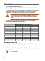
Calibration and Adjustment
Table 32 Cdate Command
Syntax
cdate<cr>
Description
cdate [yyyymmdd]<cr>
Set a new calibration and adjustment date
(format "yyyymmdd").
Show the date of the last adjustment.
Example (show current calibration date):
cdate
Cal. date
: 20150201
Example (set new calibration date):
cdate 20150630
Cal. date
: 20150630
Table 33 Ctext Command
Syntax
ctext<cr>
Description
ctext [text]<cr>
Set a new calibration and adjustment
information text.
Show adjustment information text.
Example (show current calibration text):
ctext
Cal. info
: Vaisala
Example (set new calibration text):
ctext H2 cal DGA lab sample
Cal. info
: H2 cal DGA lab sample
63
7 Vaisala Industrial Protocol
Table 34 H2 Command
Syntax
h2<cr>
da <cr>
Description
Start H2 adjustment and save the current H2
reading measured by the transmitter.
When you start the adjustment with the h2
command, normal measurement stops
temporarily and the transmitter goes into
error state. Measurement returns to normal
when you exit the H2 calibration.
h2<cr>
db<cr>
Continue H2 adjustment and enter the H2
concentration of the DGA sample.
After the adjustment, set the adjustment
date and information using the cdate and
ctext commands.
Example (save current H2 reading measured by the transmitter):
h2 <cr>
SSN=b11.04rt.10432tn1x, FW=3.85F , MDN=104400-FF02-P1, DF=0xB4B4v, L
...
7997.00 34.0852
50.11176
186.69 2654140 2652818
23
0.0
0
22.2649
0
0 wait
<"ESC key">
H2scan: da
Current H2 value is 14.4 ppm...wait...
...
79842.00 33.8725
50.11766
186.97 2654214 2652858
359
14.4
0
28.5654
200
200 wait
<"+ key">
Quit hydrogen measurement module command line operation
Example ( enter the H2 concentration of the DGA sample):
h2 <cr>
SSN=b11.04rt.10432tn1x, FW=3.85F , MDN=104400-FF02-P1, DF=0xB4B4v, L
...
7997.00 34.0852
50.11176
186.69 2654140 2652818
23
0.0
0
22.2649
0
0 wait
<"ESC key">H2scan: db
Enter actual hydrogen in ppm: 10
Set hydrogen to 10.0ppm (Y/N)? y
Enter Today's Date:
Month: 4
Day: 14
Year: 2015
...wait...
...
79842.00 33.8725
50.11766
186.97 2654214 2652858
359
10.0
10
28.5654
200
200 wait <"+ key">
Quit hydrogen measurement module command line operation
64
7 Vaisala Industrial Protocol
Table 34 on the previous page is a simplified example of the H 2
calibration and adjustment sequence with the H 2 calibration
commands.
To calibrate and adjust the H 2 measurement correctly, follow the
instructions in section H2 Calibration and Adjustment on
page 76.
Other Commands
Table 35 Filt Command
Syntax
filt [f.fff]<cr>
Description
Set the speed at which the latest moisture
and temperature measurement is integrated
into the most recent readings. The
command affects both analog output and
serial line output.
This command does not affect the H2
reading.
f.fff = Measurement filter setting, range
0.001 ... 1.0. The default value is 1.0.
n
1.0 = No filtering, latest measurement is
output without averanging
n
0.5 = Average of the last two
measurements
n
0.1 = Average of approximately 16
measurements
filt<cr>
View the current setting and prompt to enter
a new value.
Example (view the current value and set filtering to value 0.5):
filt
Filter
:
1.000
? 0.5
65
7 Vaisala Industrial Protocol
Table 36 Frestore Command
Syntax
frestore<cr>
Description
Restore factory settings. Clears all user
settings, including serial communication
settings, transmitter address, and analog
output configurations.
H2 calibration remains.
Example:
frestore
Factory settings restored
Table 37 Reset Command
Syntax
reset<cr>
Example:
reset
MHT410 / 0.1.20
66
Description
Reset the transmitter. The transmitter will
restart as if it had just been powered on.
8 MI70 Hand-Held Indicator
8
MI70 HAND-HELD INDICATOR
You can use the Vaisala MI70 Hand-Held Indicator as a temporary display for
the transmitter.
MI70 shows the readings for all the parameters measured by the transmitter.
You can also view the trend of the measurement on the graphical display, and
compare the moisture and temperature readings of MHT410 to a Vaisala MM70
reference probe.
The MI70 Hand-Held Indicator is intended to be used as display
only. You cannot use the MI70 to configure and calibrate
MHT410.
To configure the transmitter, use Modbus (see Modbus on
page 37) or Vaisala Industrial Protocol (see Vaisala Industrial
Protocol on page 38). For H2 calibration instructions, see H2
Calibration and Adjustment on page 76.
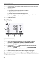
MI70 Indicator Overview
Indicator Keypad
1
2
3
67
8 MI70 Hand-Held Indicator
1
=
Function keys. The functions change according to what you are doing
with the indicator.
2
=
Arrow keys:
n
n
n
Up/down key: Move up and down in a menu.
Right key: Enter a sub-menu.
Left key: Return to the previous menu level.
To open the main menu, press any of the arrow keys and then the
function key OPEN.
3
=
Power On/Off key.
Basic Display
5
1
2
3
4
Figure 6 MI70 Basic Display
1
=
Up to three measured parameters. You can change the shown
parameters in Main menu > Display > Quantities and units .
2
=
Function key Graphic shows the readings as a curve.
3
=
Function key Hold/Save freezes the display and you can save the
reading in the MI70 memory.
4
=
Function key Record is a quick access to the Recording/Viewing
menu.
5
=
Battery indicator. Shows current status (charge) of the battery.
You can change the default function key shortcuts (Graphic, Hold/Save,
Record) to other menus or functions in Main menu > Settings > User interface
> Program shortcut keys.
68
8 MI70 Hand-Held Indicator
Graphical Display
The graphical display shows you the measurements as a curve. From the curve
you can examine the data trend and history of the last minutes.
To open the graphical display, select Graphic in the basic display or select Main
menu > Display > Graphic history > Show.
To zoom in and out, press the up/down arrow keys.
To move back and forward in the timeline, use the left/right arrow keys.
Main Menu
To open the main menu:
1. Go to the basic display.
2. Press any arrow key, then select OPEN.
In the main menu, you can configure the MI70 settings and basic display.
You can also perform certain operations with the transmitter. For more
information:
n
n
n
Holding and Saving the Display on the next page
Recording Data on page 71
Comparing Readings with MM70 Probe on page 73
Installing and Recharging the MI70 Batteries
If you are using alkaline batteries, unscrew the back plate of the indicator and
insert the alkalines. Do not attempt to recharge standard alkaline batteries.
If MI70 is ordered with rechargeable battery, it is already in place as shipped
from the factory.
To recharge the batteries:
1. Plug in charger connector to the indicator. The plug is located at the top of
the indicator, covered by rubber seal.
2. Connect the charger to wall socket. A battery symbol in the left corner of the
display starts to roll.
The recharge duration depends on the charge level of the battery. Typical
duration is 4 hours. The recommended first recharging time is 6 hours.
3. When the battery symbol stops rolling, disconnect the charger.
69
8 MI70 Hand-Held Indicator
It is not recommended to use MI70 during the first recharging.
Later on MI70 can be used while recharging.
Connecting MI70 to Service Port
n
n
n
MI70 Indicator or MM70 Moisture Meter (includes MI70
indicator, a moisture-in-oil probe and a ball valve)
Connection cable (Vaisala order code 219980)
Power supply for MHT410
1. Open the screws on the transmitter cover, and open the cover.
2. Connect the cable (219980) to the service port connector on the transmitter
and to port I or II of MI70 indicator.
3. Switch the MI70 indicator on.
Holding and Saving the Display
With the Hold/Save function, you can freeze a certain display reading. This
reading can be saved in the MI70 memory and it will be available even after
MI70 is disconnected from the transmitter.
To save a display:
1. In the basic display, select Hold/Save. Alternatively, select Main menu
> Display > Hold/Save display > Hold.
2. Press Save.
To view the saved display:
1. In the basic display, select Record > View recoded data. Alternatively,
select Main menu > Recording/Viewing > View recoded data.
A list of saved displays and data recordings appears. The icons on the left
of the date and time indicate whether the file is a saved display or a longer
recording of data:
70
=
Saved display
=
Data recording
8 MI70 Hand-Held Indicator
2. Select the saved display based on date and time by pressing the right arrow
key.
Recording Data
With MI70, you can record transmitter measurement data over a certain period at
chosen intervals. These recordings are saved in MI70 memory and are available
even after MI70 is disconnected from the transmitter.
Starting and Stopping the Recording
You can record the measurement of the parameters that are currently shown on
the MI70 basic display. You can change the shown parameters in Main menu >
Display > Quantities and units.
1. In the basic display, select Record > Record data. Alternatively, select
Main menu > Recording/Viewing > Record data.
2. If needed, change the interval and duration of the recording in the RECORD
DATA view. The measurement intervals and maximum recording times are
shown in Table 38 on the next page.
If you set the duration to "Memory full", the recoding will
continue until the MI70 memory is full or until you stop the
recording manually. The maximum recording time will be
shown when you start the recording.
71
8 MI70 Hand-Held Indicator
3. Select Start/Stop recording > Start.
The recording will continue until the duration has passed or until you stop
the recording manually.
You can switch the MI70 off during recording to save battery. A progress bar
is shown on the display every 10 seconds (or all the time, if charger is
connected). The progress bar shows the amount of recorded data.
Do not disconnect the probe when the data recording is on,
even if the indicator is off. This may cause loss of recorded
data.
4. To stop the recording manually, in the basic display select Record >
Record data > Start/stop recording > Stop.
Table 38 Measurement Intervals and Max. Recording Times
Recording Interval
Maximum Recording Time (memory full)
1 Parameter
2 Parameters
3 Parameters
1s
45 min
22 min
15 min
5s
3h
113 min
75 min
15 s
11 h
5h
3h
30 s
22 h
11 h
7h
1 min
45 h
22 h
15 h
5 min
9 days
4 days
3 days
15 min
28 days
14 days
9 days
30 min
56 days
28 days
18 days
1h
113 days
56 days
37 days
3h
339 days
169 days
112 days
12 h
1359 days
678 days
451 days
Viewing Recorded Data
1. In the basic display, select Record > View recoded data. Alternatively,
select Main menu > Recording/Viewing > View recoded data.
A list of saved displays and data recordings appears. The icons on the left
of the date and time indicate whether the file is a saved display or a longer
recording of data:
=
72
Saved display
8 MI70 Hand-Held Indicator
=
Data recording
2. Select the recording based on date and time by pressing the right arrow
key.
Deleting Recorded Files
You can delete recorded data files one by one or all files at the same time.
To delete a single data file:
1. In the basic display, select Record > View recoded data. Alternatively,
select Main menu > Recording/Viewing > View recoded data.
2. Select the data file based on date and time, and select DELETE.
3. Confirm by selecting YES.
To delete all data files (recordings and saved displays):
1. In the basic display, select Record. Alternatively, select Main menu
> Recording/Viewing.
2. Select Clear data memory.
3. Confirm by selecting YES.
Comparing Readings with MM70 Probe
n
Vaisala HUMICAP® Hand-held Moisture Meter for Oil MM70
You can use MI70 to compare the measurement readings of MHT410 to an
MM70 reference probe.
73
8 MI70 Hand-Held Indicator
The indicator shows the readings from both devices at the same time. You can
also show the difference in reading for water activity (Δaw) and temperature
(ΔT).
1. Install the MM70 probe in the same transformer as MHT410. For
instructions, see the MM70 User's Guide (available at
www.vaisala.com/manuals).
2. Turn off the MI70 indicator.
3. If MHT410 is not connected to MI70, connect it to one of the MI70 ports (I or
II).
4. Connect the MM70 probe to the other MI70 port.
5. Turn on the MI70.
The basic display now shows the readings from both devices. The port of the
device is indicated next to the measured parameter. You can change the shown
parameters in Main menu > Display > Quantities and units.
Figure 7 Example of MI70 Display with MHT410 in Port I and MM70 Probe in Port II. Shown
Parameters: aw (I), aw (II), Δ aw.
Changing the Rechargeable Battery Pack
You can order a new rechargeable battery pack from Vaisala.
1. Open the back plate of the indicator by opening the screw of the back plate.
2. Remove the old battery pack. Detach the black connector by gently pulling it
up from the wires.
3. Connect the black connector of the new battery pack. Make sure the
position of the connector is as shown in Figure 8 on the facing page (red
and black wires are on the upper edge of the connector). Do not push the
connector with conducting material.
4. Place the battery pack, close the back plate and tighten the screw.
74
8 MI70 Hand-Held Indicator
5. Recharge the indicator before use. For more information, see Installing and
Recharging the MI70 Batteries on page 69.
In case you are installing a battery pack and you have a device with alkaline
batteries, remove the metal contact before installing the battery pack.
Figure 8 Installing the Battery Pack
75
9 Calibration and Adjustment
9
CALIBRATION AND
ADJUSTMENT
MHT410 is fully calibrated and adjusted as shipped from factory.
H2 Calibration and Adjustment
You can calibrate MHT410 for H 2 by comparing the H 2 reading on the MHT410
to the H2 concentration of a laboratory-analyzed DGA oil sample. There is no
need to remove the transmitter from the transformer to perform calibration and
adjustment.
In the calibration procedure, you take a DGA oil sample from the transformer and
save the H2 concentration measured by the transmitter at that time. When you
have analyzed the H 2 concentration of the sample, you enter the analyzed H 2
reading to MHT410. The transmitter then implements the adjustment to the H 2
measurement.
Follow the instructions in sections Taking DGA Sample and Saving Current H2
Reading below and Entering DGA H2 Reading to Transmitter on page 78.
Taking DGA Sample and Saving Current H2 Reading
n
n
Tools for taking a DGA oil sample
Connection to the transmitter using Vaisala Industrial Protocol
in one of the following ways:
o Service port (see Connecting via Service Port on page 39)
o RS-485 line of the screw terminals
In the following instructions, the keyboard input by the user is in
bold type.
When you start the adjustment with the h2 command, normal
measurement stops temporarily and the transmitter goes into
error state. Measurement returns to normal when you exit the H 2
calibration.
76
9 Calibration and Adjustment
1. Take the DGA oil sample from the transformer.
2. Open the connection on Vaisala Industrial Protocol (see Connecting via
Service Port on page 39).
3. Start the calibration sequence with the command h2. The transmitter starts
outputting H 2 measurement data.
h2
SSN=b11.04rt.10432tn1x, FW=3.85F
L
...
, MDN=104400-FF02-P1, DF=0xB4B4v,
4. Stop the output by pressing the Esc key:
...
7997.00 34.0852
50.11176
0.0
0
22.2649
<"ESC key">
H2scan:
186.69
0
2654140
0 wait
2652818
23
5. Save the H2 reading with the da command:
H2scan: da
Current H2 value is 14.4 ppm...wait...
6. When the H2 measurement output resumes, exit the calibration sequence
by pressing the + key:
...
79842.00 33.8725
50.11766
186.97 2654214 2652858
14.4
0
28.5654
200
200 wait <"+ key">
Quit hydrogen measurement module command line operation
359
Do not exit the calibration sequence before the H 2
measurement output has resumed.
If the H2 output does not resume automatically, issue the
command g to start the H2 output, and then exit the
calibration sequence.
Entering DGA H2 Reading to Transmitter
n
Connection to the transmitter using Vaisala Industrial Protocol
in one of the following ways:
o Service port (see Connecting via Service Port on page 39)
o RS-485 line of the screw terminals
77
9 Calibration and Adjustment
When you start the adjustment with the h2 command, normal
measurement stops temporarily and the transmitter goes into
error state. Measurement returns to normal when you exit the H 2
calibration.
1. Open the connection on Vaisala Industrial Protocol (see Connecting via
Service Port on page 39).
2. Start the calibration sequence with the command h2. The transmitter starts
outputting H 2 measurement data.
h2
SSN=b11.04rt.10432tn1x, FW=3.85F
L
...
, MDN=104400-FF02-P1, DF=0xB4B4v,
3. Stop the output by pressing the Esc key:
...
7997.00 34.0852
50.11176
0.0
0
22.2649
<"ESC key">
H2scan:
186.69
0
2654140
0 wait
2652818
23
4. Enter the DGA H2 reading with the db command:
H2scan: db
Enter actual hydrogen in ppm: 10
Set hydrogen to 10.0ppm (Y/N)? y
Enter Today's Date:
Month: 4
Day: 14
Year: 2015
...wait...
5. When the H2 measurement output resumes, exit the calibration sequence
by pressing the + key:
...
79842.00 33.8725
50.11766
186.97 2654214 2652858
10.0
10
28.5654
200
200 wait <"+ key">
Quit hydrogen measurement module command line operation
359
Do not exit the calibration sequence before the H 2
measurement output has resumed.
If the H2 output does not resume automatically, issue the
command g to start the H2 output, and then exit the
calibration sequence.
78
9 Calibration and Adjustment
6. Enter the calibration date and information using the cdate and ctext
commands. For example:
cdate 20150630
Cal. date
: 20150630
ctext H2 cal DGA lab sample
Cal. info
: H2 cal DGA lab sample
RS & T Calibration and Adjustment
MHT410 is calibrated at the factory for RS and T. The recommended calibration
interval for RS & T is 3 years. Vaisala provides calibration and adjustment
services. For more information, visit the Vaisala calibration website at
www.vaisala.com/calibration.
79
10 Troubleshooting
10
TROUBLESHOOTING
Error States
MHT410 has the following states that indicate a problem with the transmitter:
Error indication on analog outputs at 3.5 mA (default):
o With hydrogen measurement errors, the hydrogen channel is in error state.
o With moisture in oil measurement errors, the moisture in oil channel is in
error state.
o With temperature measurement errors, the temperature and moisture in oil
channels are in error state.
o With general errors, all three channels are in error state.
Error messages on the serial line:
o Modbus statuses (see Modbus Device Status Bits on page 101)
o Vaisala Industrial Protocol error list
n
n
Table 39 Possible Error Messages via Vaisala Industrial Protocol
Error Number
and Text
0001
Temperature
measurement
error
0002
Frequency
measurement
error
80
Description
Action
Remove the transmitter from the
Temperature
measurement raw value is transformer and visually check the integrity
outside the allowed range. of the transmitter and the sensor area of
the probe body.
Moisture measurement
raw value is outside the
allowed range.
Contact Vaisala technical support (see
Technical Support on page 83).
10 Troubleshooting
Error Number
and Text
0004
H2
measurement
error
0008
H2 module
communication
error
Description
Action
H2 module has reported
an error.
Check the connection to the H2 module:
1. Connect using Vaisala Industrial
protocol.
2. Open the connection to H2 module by
giving the command h2.
No message was received
from H2 module in the last
5 seconds.
3. Verify whether the transmitter starts
outputting H2 measurement data.
4. Close the connection to H2 module by
pressing the + key.
Contact Vaisala technical support (see
Technical Support on page 83).
0010
RH sensor
failure
Remove the transmitter from the
Capacitance value is
outside the allowed range. transformer and visually check the integrity
of the transmitter and the sensor area of
the probe body.
Contact Vaisala technical support (see
Technical Support on page 83).
0020
Temperature
too high/low
Measured temperature is
outside the error limits
(below -45 °C or above
+125 °C).
Ensure that the operating temperature is
within the valid range -40 … +120 °C.
If the error persists, contact Vaisala
technical support (see Technical Support
on page 83).
81
10 Troubleshooting
Error Number
and Text
0040
Program flash
CRC error
Description
Action
Internal transmitter
failure.
Contact Vaisala technical support (see
Technical Support on the facing page).
0080
Parameter
flash check
sum error
0100
INFOA check
sum error
0200
SCOEFS
check sum
error
0400
CURRENT
check sum
error
0800
DEFAULT
(factory) check
sum error
1000
General flash
failure W/R
In case of constant error, please contact Vaisala. See Technical Support on the
facing page.
Changing Bleed Screw
If oil starts flowing out from the bleed screw on the mounting nut, tighten the
bleed screw. If oil still flows out, change the bleed screw.
n
n
n
n
82
New bleed screw (provided in the MHT410 installation kit)
Medium wrench (36 mm)
Large wrench (50 mm)
Allen key (3 mm, provided in the MHT410 installation kit)
10 Troubleshooting
1. Loosen the tightening nut of the transmitter.
2. Pull the transmitter outward so that the probe body is out of the ball valve.
3. Close the ball valve.
4. Turn the mounting nut so that the bleed screw is on top of the nut.
5. Remove the bleed screw from the mounting nut.
6. Install a new bleed screw and tighten it firmly.
7. Tighten the mounting nut until the connection is oil-tight.
8. Push the probe to the same installation depth.
9. Tighten the small tightening nut with a wrench until it the probe is securely
fastened.
Technical Support
For technical questions, contact the Vaisala technical support by e-mail at
[email protected]. Provide at least the following supporting information:
n
n
n
n
Name and model of the product in question
Serial number of the product
Name and location of the installation site
Name and contact information of a technically competent person who can
provide further information on the problem.
For contact information of Vaisala Service Centers, see
www.vaisala.com/servicecenters.
83
11 Technical Data
11
TECHNICAL DATA
Table 40 Measurement Performance
Property
Hydrogen measurement
Measurement range (in oil)
Accuracy (in oil temp. range -20 ... +60 °C,
-4 ... +140 °F)
Repeatability
Specification
0 ... 5000 ppm
±20 % of reading or ±25 ppm
(whichever is greater)
±10 % of reading or ±15 ppm
(whichever is greater)
Minimum detection limit
20 ppm
Typical long-term stability
3 % of reading / year
Cross sensitivity to other gases
< 2 % (CO2, C2H2, C2H4, CO)
Response time
63 % of full response
2.5 hours (when sensor is not in
reference cycle)
90 % of full response
17 hours
Warm-up time
2 hours, 12 hours for full
specification
Sensor
Catalytic palladium-nickel alloy film
solid-state sensor
Moisture in oil measurement
Measurement range (in oil)
0...100 %RS (aw 0 ... 1)
Accuracy (including non-linearity, hysteresis and
repeatability) at 20 °C (68 °F)
0 ... 90 %RS (aw 0 ... 0.9)
±2 %RS (aw ±0.02)
90 ... 100 %RS (aw 0.9 ... 1.0)
±3 %RS (aw ±0.03)
Response time
(90 %, at +20 °C in still oil)
10 min
Sensor
HUMICAP® 180L2
Temperature measurement
Measurement range
84
-40 ... +120 °C (-40 ... +248 °F)
Accuracy at +20 °C (+68 °F)
± 0.2 °C (0.36 °F)
Sensor
Pt1000 RTD Class F0.1 IEC
60751
11 Technical Data
Table 41 Operating Environment
Property
Specification
Oil type
Mineral oil
Operating humidity range
0 ... 100 %RH, condensing
Operating temperature range (electronics)
-40 ... +60 °C (-40 ... 140 °F)
Storage temperature range
-40 ... +60 °C (-40 ... 140 °F)
Pressure tolerance (probe, short-term)
Max. 10 bara
Pressure tolerance (probe, continuous)
Max. 4 bara
Integrated protection for short power outages
Electromagnetic compatibility:
> 3 seconds
n
Complies with EMC standard EN61326-1, Industrial environment
n
Complies with CISPR22 class B emission limits when DC powered
n
Fulfills the requirements of IEC 61000-6-5 in the following tests:
o IEC 61000-4-2
o IEC 61000-4-3
o IEC 61000-4-4
o IEC 61000-4-5
o IEC 61000-4-6
o IEC 61000-4-8 (100 A/m continuous)
o IEC 61000-4-11
o IEC 61000-4-12
(The list will be continuously updated)
85
11 Technical Data
Table 42 Connections And Outputs
Property
Specification
Operating voltage
15 ... 30 VDC, 24 VAC (±15 %) (power supply input is
galvanically isolated)
Power consumption
Analog output (current)
4 W, typical
Three isolated 4 ... 20 mA, passive
External load
Max. 500 Ω
Isolation
Max 1.5 kV (DC)
Error status indication in case
of device error
3.5 mA default, user configurable for each channel
Accuracy of analog outputs
± 0.5 % full scale
± 0.006 % / °C full scale
Temperature dependence of
the analog outputs
Isolated RS-485 half-duplex,
Digital output
RS-485 (Service Port)
Protocols
MODBUS RTU, serial ASCII commands
Wire size AWG 22-14
Screw terminals
Single wire (solid) 1.5 mm2
Stranded wire (flex.) 1.0 mm2
Recommended wire torque 0.4 Nm
Table 43 Mechanics
Property
Specification
Mechanical connection on transmitter
1.5" NPT (male)
Cable bushing (optional)
M20x1.5 for cable diameter 8 ... 11mm/0.31 ...
0.43"
Conduit fitting (optional)
1/2" NPT
Interface cable (optional, preassembled)
5 meters, 9.2 mm outer diameter
Housing material
AlSi 10 Mg
Housing classification
IP66
Transmitter weight without cables
4.1 kg
Table 44 Other
Property
Specification
Self-diagnostics indication
Status LEDs, analog output, MODBUS
Integrated data logging
capabilities
Non-volatile memory, up to 44 years storage with default
logging
86
11 Technical Data
Property
Specification
Individual functional test
reports
Calibration test reports for moisture, hydrogen and
temperature
Probe leak test report (5 bara nominal)
Factory warranty
5 years
Table 45 Display with Relays (External Option)
Property
Specification
Pre-configured range for hydrogen
0 ... 5000 ppm
Relay 1 trigger limit 200 ppm (hi)
Pre-configured alarm relays (user reconfigurable)
Input
Relay 2 trigger limit 1500 ppm (hihi)
4... 20 mA, loop-powered
0.05 % of span (-10 ... +60 °C)
Accuracy
2 x solid state (SSR)
Max. 250 VAC, 150 mA
Display
4-digit red LED, 14.5 mm
Dimensions
100 x 100 x 57 mm (WHD)
Case protection
IP65
Case material and color
ABS-plastic, grey
Cable glands
2 x M16x1.5
Spare Parts and Accessories
Part number
Description
219690
USB cable for PC connection
242422
External DIN rail power 100 ... 240 VAC to 24 VDC
CBL210392-5MSP
5 meter shielded PUR cable
CBL210392-10MSP
10 meter shielded PUR cable
214728SP
Cable gland
236620SP
Detachable screw terminal block
242003
Loop-powered external display, Nokeval 302 (with alarm
relays)
219980
MI70 connection cable
214780SP
Conduit fitting
87
11 Technical Data
Dimensions
334
202
132
50
36
94.5
38.5
74
20.6
51
76.5
25.5
1.5” NPT
222
270
150
125
Cable Ø 8...11 mm
88
11 Technical Data
Wiring Diagrams
mA
4...20 mA
RL = 0...500 Ω
15...30 VDC,
loop powered
11
12
13
14
15
-Vs
10
+Vs
SHLD
9
D+
8
16
mA
mA
4...20 mA
RL = 0...500 Ω
15...30 VDC,
loop powered
7
D-
6
RS
GND
5
SHLD
4
-CH1
3
POWER
RS-485
+CH1
2
-CH2
-CH3
1
+CH2
+CH3
ANALOG OUTPUTS
4...20 mA
RL = 0...500 Ω
15...30 VDC,
loop powered
Power supply
15...30 VDC
Or 24 VAC ± 15%
Figure 9 Wiring Option 1: Separate Loop Powering and Galvanic Isolation for Analog Outputs.
In transmitters ordered with Vaisala cable CBL210392-5M, the cable is pre-wired according to
this option.
Table 46 Vaisala Cable CBL210392-5M Wire Colors (When Pre-Wired)
Terminal
Wire Color
+CH3
Green
-CH3
White-Green
+CH2
White
-CH2
Gray-White
+CH1
Yellow
-CH1
White-Yellow
RSGND
Purple
D-
Black
D+
Yellow-Brown
+Vs
Red
-Vs
Blue
89
11 Technical Data
mA
+
mA
9
11
12
13
14
15
-Vs
10
+Vs
SHLD
8
D+
7
D-
6
RS
GND
5
POWER
SHLD
4
-CH1
3
RS-485
+CH1
2
-CH2
-CH3
1
+CH2
+CH3
ANALOG OUTPUTS
16
mA
-
4...20 mA
RL = 0...500 Ω
15...30 VDC,
loop powered
Power supply
15...30 VDC
Or 24 VAC ± 15%
Figure 10 Wiring Option 2: Common Loop Powering And Galvanic Isolation for Analog
Outputs
mA
mA
9
11
12
13
14
15
-Vs
10
+Vs
SHLD
8
D+
7
D-
6
RS
GND
5
POWER
SHLD
4
-CH1
3
RS-485
+CH1
2
-CH2
-CH3
1
+CH2
+CH3
ANALOG OUTPUTS
16
mA
Power supply
15...30 VDC
Figure 11 Wiring Option 3: Non-Isolated Configuration for Analog Outputs Sharing
Transmitter Power Supply
90
11 Technical Data
mA
mA
9
11
12
13
14
15
-Vs
10
+Vs
SHLD
8
D+
7
D-
6
RS
GND
5
POWER
SHLD
4
-CH1
3
RS-485
+CH1
2
-CH2
-CH3
1
+CH2
+CH3
ANALOG OUTPUTS
16
Power supply
15...30 VDC
mA
Figure 12 Wiring Option 4: Alternative Wiring to Option 3, Providing Reduced Current Loop
Area for Analog Outputs
Recycling
Recycle all applicable material.
Disposal of Vaisala products is to be done according to local
laws and regulations. We encourage end-users to segregate the
products from other waste at end-of-life and use best available
recycling practices to minimize related environmental impacts.
Almost all of the parts in our products can be recovered as
material or energy. If applicable, Vaisala recommends removing
the battery unit before recycling the rest of the device as typical
electronic waste. The battery unit can be recycled separately in
accordance with local waste management practices and
regulations. Integrated small sized batteries are typically left in
place and removed by professionals at the recycling facilities.
Table 47 Materials for Recycling
Part
Materials
Packaging
Product package
Cardboard
Padding foam
Polyethylene
Device parts
1
Electronics housing and front cover
AlSi 10Mg
91
11 Technical Data
Part
Materials
2
Product label
Polyester
3
Circuit board mounting plate
EN 1.4404
4
Flange gasket
5
Probe shaft
Silicone
Outer shaft: EN 1.4404
Inner plastic: Polyphenylene sulfide,
glass-fiber reinforced
6
Ventilation valve
Polyester
7
Sealing ring
PTFE
8
Tightening nut
EN 1.4404
9
Mounting nut
EN 1.4404
10
Filter
EN 1.4404
11
Circuit board cover
Polypropylene
12
Terminal blocks
Polyamide PA66
13
Grounding cable
Copper wire
14
Plug for cable lead-through
Polystyrol
15
Cable gland
Nickel-plated brass
16
Weather shield
EN 1.4404
17
Sorbent packet
Silica
18
Thread cap
LDPE
Screws
92
A4
1 2
11
12
3
13
4
5
14 15
1
6
16
7 8
17 18
9
10
11 Technical Data
93
A Appendix: Operating Principle
A
APPENDIX: OPERATING
PRINCIPLE
Power transformers are critical components in the electric grid. Age, increased
load levels and network failures all take a toll on transformers, increasing the
risk of unpredicted faults and outages.
n
n
Hydrogen levels and their rate of change indicate the severity of a fault
situation.
Moisture has a direct impact on the lifetime of a transformer. Oil moisture has
a significant effect on transformer cellulose condition and the oil’s ability to
insulate. These changes in moisture levels can occur rapidly.
Continuously monitoring hydrogen and moisture levels with an in-situ probe is
the first step in extending the life of a transformer through implementation of
predictive maintenance practices leading to lower total cost of ownership.
Figure 13 Measuring Hydrogen and Moisture in Oil with MHT410
The optimal locations for the MHT410 hydrogen, moisture and temperature
sensors are presented in Table 48 on the facing page.
94
A Appendix: Operating Principle
Table 48 Optimal Sensor Locations
Valve in Radiator Pipe
n
Moisture and temperature sensors are
directly in the oil flow. This is because
water molecule diffusion rate in oil is
slow, and therefore moisture must be
measured in moving oil.
n
Hydrogen sensor is in the valve area.
This is because the hydrogen sensor
needs an accurate temperature control,
and therefore hydrogen must be
measured in still oil.
Valve in Transformer Wall
Tip of the probe is level with transformer
inner wall. No part of the probe must enter
the transformer chamber. All sensors
remain within the valve area.
Severe risk of death and of
damage to transformer:
Pay attention to transmitter installation
depth and possible energized parts
inside the power transformer to
minimize electric shock hazard and
equipment damage.
Method Used for Measuring Moisture in Oil
MHT410 measures water in oil in terms of relative saturation (%RS) which can
be determined as follows: relative saturation indicates the amount of water oil in
the scale of 0 ... 100 %RS. In this scale, 0 %RS is an indication of completely
water free oil and 100 %RS an indication of oil fully saturated with water. Water
is present in free form.
The most advanced feature which distinguishes the measurement of relative
saturation (%RS) from the traditional measurement of absolute water content (in
ppm) is that the saturation point remains stable regardless of the oil type, aging
of oil or additives used. As relative saturation exceeds 90 %RS in any system,
there is a risk for segregation (especially if the temperature decreases). The
relative saturation is used for alarming at the point of > 90 %RS that the risk for
free water in the system is obvious.
The most important advantages of this system are the fact that relative saturation
is immune to the aging of oil and to additives, and that the MHT410 transmitter
can be used for continuous on-line measurements.
Transformer Oil
The determination of moisture in oil is an essential part of a comprehensive
transformer maintenance program. Aging and deterioration increase the
95
A Appendix: Operating Principle
capacity of oil to absorb water. The primary interest in transformers is to measure
the water not in oil but in the cellulosic insulation around the transformer
windings. The MHT410 method provides for a reliable detection of the aging of
oil and possible leakages.
Moisture level in oil is a true indicator of moisture present in the paper insulation.
Heating and cooling have a considerable effect on moisture levels in oil. The
paper insulation around the transformer windings tends to lose moisture as
temperature rises. This moisture is absorbed by the oil surrounding it.
Oil-immersed transformers rely on the oil for cooling, protection from corrosion
and as an important component of their insulation. Excessive moisture content in
oil causes accelerated aging of the insulation materials and reduces their
dielectric strength. In extreme cases, this can result in arcing and short circuits
within the windings. Accurate moisture measurements can also warn about
leaks in the oil system, as water is absorbed from the surrounding air.
The water solubility of oil is also temperature dependent. In general, water
solubility increases as temperature rises, see Figure 14 below.
WATER SOLUBILITY IN MINERAL TRANSFORMER OIL
10000
1000
average water
solubility
PPM
range of
variation due to
oil type
range of
variation due to
oil type
100
10
0
10
20
30
40
50
60
70
80
90
100
Temperature (°C)
Figure 14 Water Solubility of Transformer Oils versus Temperature. The margins show the
range of variation of water solubility found in mineral oils.
In addition, it must be noted that the capacity of oil to absorb water depends both
on the chemical structure of the oil and the additives.
96
B Appendix: Modbus Reference
B
APPENDIX: MODBUS
REFERENCE
Function Codes
Conformance class 0 function codes are enough to access the measurement
data and configuration settings of MHT410.
Device identification data can be read out only with the function code dedicated
for that purpose (43 / 14).
Table 49 Supported Function Codes
Function
Code
Name
Class
Notes
03 (0x03)
Read Holding Registers
Class 0
43 / 14
Read Device Identification
See Measurement Data
(Read Only) on page 99
for available registers.
See Device Identification
Objects on page 102 for
available device
identification objects.
(0x2B / 0x0E)
Register Map
All data available via the Modbus interface is grouped in three contiguous
blocks of registers as described in Table 50 below.
Table 50 MHT410 Modbus Register Blocks
Logical Address (decimal)
Data Format
Description
1 ... 54
32-bit IEEE float
257 ... 271
16-bit signed integer
Measurement data (read
only)
513 ... 513
16-bit signed integer
Status registers (read-only)
The addresses are 1-based decimal Modbus data model addresses. Subtract 1
to get address field values used in Modbus Protocol Data Unit (PDU).
The register map is the same for all Modbus function codes. For example,
function codes 03 and 04 return exactly same result.
97
B Appendix: Modbus Reference
Data Encoding
All numeric values are available both in 32-bit IEEE floating point and 16-bit
signed integer formats.
32-Bit Floating Point Format
Floating point values are represented in standard IEEE 32-bit floating point
format. Least-significant 16 bits of floating point numbers are placed at the
smaller Modbus address as specified in Open Modbus TCP Specification,
Release 1.0. This is also known as "little-endian" or "Modicon" word order.
Despite the specification, some Modbus masters may expect
"big-endian" word order (most-significant word first). In such
case, you must select "word-swapped" floating point format in
your Modbus master for MHT410 Modbus registers.
A "quiet NaN" value is returned for unavailable values. A quiet NaN is, for
example, 0x7FC00000; however, the master should understand any NaN value.
A complete 32-bit floating point value should be read and written
in a single Modbus transaction.
16-Bit Integer Format
16-bit integer values are scaled to include the necessary decimals (see
corresponding register table for the scaling factor) and represented as described
in the following table.
Table 51 16-bit Signed Integer Format Details
Value
Description
0x0000…0x7FFE
Value in range 0…32766
0x8002…0xFFFF
Value in range -32766…-1 (2’s complement)
0x8000
Value is not available (quiet NaN)
Some values may exceed the signed 16-bit range even in
normal operation. To access such values, use the floating point
registers instead.
98
B Appendix: Modbus Reference
Measurement Data (Read Only)
Table 52 Modbus Measurement Data Registers
Logical
Address
(decimal)
PDU
Address
(hexadecimal)
1
00 00
2
00 01
3
00 02
4
5
6
00 05
MSW
7
00 06
H2, Weekly ROC LSW
8
00 07
MSW
9
00 08
10
00 09
15
00 0E
16
00 0F
17
00 10
18
00 11
19
00 12
20
00 13
21
00 14
22
00 15
23
00 16
24
00 17
25
00 18
26
27
28
00 1B
257
01 00
258
Data
Format
Unit
32-bit float
ppm (in oil)
32-bit float
ppm (in oil)
32-bit float
ppm (in oil)
32-bit float
ppm (in oil)
32-bit float
ppm (in oil)
32-bit float
%RS
32-bit float
ppm
32-bit float
ppm
32-bit float
ppm
32-bit float
ppm
32-bit float
ppm
32-bit float
°C
H2, 1 h average
16-bit
integer
ppm (in oil)
01 01
H2, 24 h
average
16-bit
integer
ppm (in oil)
259
01 02
H2, Daily ROC
16-bit
integer
ppm (in oil)
260
01 03
H2, Weekly ROC
16-bit
integer
ppm (in oil)
Register Description
H2, 1 hour
average
LSW
LSW
00 03
H2, 24 hour
average
00 04
H2, Daily ROC
MSW
MSW
LSW
H2, Monthly
ROC
LSW
Oil moisture,
relative
saturation
LSW
Oil moisture,
current
LSW
Oil moisture, 24
h average
LSW
Oil moisture,
Daily ROC
LSW
Oil moisture,
Weekly ROC
LSW
LSW
00 19
Oil moisture,
Monthly ROC
00 1A
Oil temperature
MSW
MSW
MSW
MSW
MSW
MSW
MSW
LSW
MSW
99
B Appendix: Modbus Reference
Logical
Address
(decimal)
PDU
Address
(hexadecimal)
261
Register Description
Data
Format
01 04
H2, Monthly
ROC
16-bit
integer
ppm (in oil)
264
01 07
Oil moisture,
relative
saturation
16-bit
integer
%RS*10
265
01 08
Oil moisture,
current
16-bit
integer
ppm*10
266
01 09
Oil moisture,
24h average
16-bit
integer
ppm*10
267
01 0A
Oil moisture,
Daily ROC
16-bit
integer
ppm*10
268
01 0B
Oil moisture,
Weekly ROC
16-bit
integer
ppm*10
269
01 0C
Oil moisture,
Monthly ROC
16-bit
integer
ppm*10
270
01 0D
Oil temperature
16-bit
integer
°C *10
513
02 00
Device status
bits
16-bit
See Status
Registers on
the facing
page.
Unit
Legend:
PDU address
LSW
MSW
16-bit integer
32-bit float
=
=
=
=
=
Actual address bytes used in a Modbus Protocol Data Unit
Least Significant Word (bits 15...0)
Most Significant Word (bits 31...16)
Numeric value in range -32768...32767
Floating point number encoded according to IEEE 754
A complete 32-bit value (two Modbus registers) must be read and written in a
single Modbus transaction.
A “quiet NaN” (0x7FC00000) value is returned for unavailable floating-point
values and NaN (0x8000) for unavailable integer values (e.g. in case of
measurement error).
Several registers may be read in one transaction, even if there are gaps in the
register map. Registers not listed above contain typically value NaN or 0.
Values may be unavailable in case of device failure. Read status registers or
exception status outputs to check for failures.
100
B Appendix: Modbus Reference
Status Registers
Table 53 Modbus Status Registers for MHT410
Register Description
Logical Address
Data Format
Device status bits
513
16-bit integer
Table 54 Modbus Device Status Bits
Output
Output Name
Notes
0
Critical Error active
Maintenance needed.
1
Error active
2
RH measurement error
3
T measurement error
Device may recover
automatically.
Remove the transmitter from the
transformer and visually check
the integrity of the transmitter and
the sensor area of the probe
body.
(bit number)
Contact Vaisala technical support
(see Technical Support on
page 83).
4
H2 measurement error
Check the connection to the H2
module:
1. Connect using Vaisala
Industrial protocol.
2. Open the connection to H2
module by giving the
command h2.
3. Verify whether the
transmitter starts outputting
H2 measurement data.
4. Close the connection to H2
module by pressing the +
key.
Contact Vaisala technical support
(see Technical Support on
page 83).
5
Other error
6
H2 alarm level exceeded
Contact Vaisala technical support
(see Technical Support on
page 83).
101
B Appendix: Modbus Reference
Device Identification Objects
MHT410 Modbus conforms to the extended identification level defined in the
Modbus Application Protocol Specification V1.1b. Both stream access and
individual access to the objects is supported. Basic device identification consists
of objects 0x00…0x02. Those values should be used if the device must be
identified to establish its Modbus capabilities.
Table 55 MHT410 Device Identification Objects
Object ID
(Decimal)
Object ID
(Hexa-
Object Name
Example Contents
decimal)
0
00
VendorName
"Vaisala"
1
01
ProductCode
2
02
MajorMinorVersion
"MHT410"
Software version (for
example "1.2.3")
3
03
VendorUrl
"http://www.vaisala.com/"
4
04
ProductName
"Vaisala Moisture, Hydrogen
and Temperature
Transmitter MHT410 for
Transformer Oil"
128
80
SerialNumber
Transmitter serial number
(for example, "K0710040")
129
81
Calibration date
Date of the factory calibration
130
82
Calibration text
Information text of the factory
calibration
Object numbers above 127 are Vaisala-specific device information objects.
Exception Responses
Table 56 MHT410Modbus Exception Responses
Code
Name
Reason
01
ILLEGAL FUNCTION
Unsupported function code
02
ILLEGAL DATA ADDRESS
Address out of valid ranges
03
ILLEGAL DATA VALUE
Otherwise invalid request
Accessing unavailable (unsupported or temporarily missing) measurement data
does not generate an exception. “Unavailable” value (a quiet NaN for floating
point data or 0x0000 for integer data) is returned instead. An exception is
generated only for any access outside the register blocks defined in Table 50 on
page 97.
102
C Appendix: Moisture PPM Calculation for Transformer Oils
C
APPENDIX: MOISTURE PPM
CALCULATION FOR
TRANSFORMER OILS
Traditionally, moisture in transformer oil is measured in ppm units. The ppm
output shows the average mass concentration of water in oil.
MHT410 has an option for ppm output.
Calculation Model with Average Coefficients
The calculation model of MHT410 is based on the average water solubility
behavior of transformer oils. The ppm output is calculated as follows:
ppm = aw × 10 (A/(T+273.16)+B)
Where
aw
=
A, B =
T
=
water activity
coefficients (average/oil specific)
temperature (°C)
Generally, moisture in oil measurement with MHT410 has an accuracy of
±2 ... 3 % of the reading. If additional accuracy is needed, see Calculation Model
with Oil Specific Coefficients below.
Calculation Model with Oil Specific Coefficients
For additional accuracy, an oil specific calculation model can be used. An oil
sample has to be sent to Vaisala for modeling. As a result, the specific
coefficients (A and B: see formula in Calculation Model with Average
Coefficients above) for the transformer oil are determined by Vaisala. Using
these coefficients increases measurement accuracy.
The determined coefficients of the transformer oil can be programmed to the
MHT410 by Vaisala.
103
www.vaisala.com
*M211737EN*