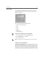
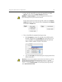
Download Leaf Capture V8 User Guide

Transcript
399Z3R632F
User Guide
English
Leaf Capture V8
www.creo.com/leaf
Copyright
Copyright © 2004 Creo Inc. All rights reserved.
No copying, distribution, publication, modification, or incorporation of this document, in whole or part, is
permitted without the express written permission of Creo. In the event of any permitted copying, distribution,
publication, modification, or incorporation of this document, no changes in or deletion of author attribution,
trademark legend, or copyright notice shall be made.
No part of this document may be reproduced, stored in a retrieval system, published, used for commercial
exploitation, or transmitted, in any form by any means, electronic, mechanical, photocopying, recording, or
otherwise, without the express written permission of Creo Inc.
This document is also distributed in Adobe Systems Incorporated's PDF (Portable Document Format). You may
reproduce the document from the PDF file for internal use. Copies produced from the PDF file must be
reproduced in whole.
. ...................................................................................................
Trademarks
The Creo wordmark, Creo logo, and the names of the Creo products and services referred to in this document are
trademarks of Creo Inc.
Adobe, Acrobat, and the Acrobat logo are registered trademarks of Adobe Systems Incorporated, and are
registered in the U.S. Patents and Trademark Office and may be registered in other jurisdictions.
Apple, AppleTalk, AppleShare, EtherTalk, LocalTalk, Macintosh, and LaserWriter are trademarks of Apple
Computer, Inc.
Microsoft, Windows, Windows 2000, and Windows NT are trademarks or registered trademarks of Microsoft
Corp.
Other brand or product names are the trademarks or registered trademarks of their respective owners.
. ...................................................................................................
FCC Compliance
The Creo equipment referred to in this document complies with the requirements in Part 15 of FCC Rules for a
Class A computing device. Operation of the Creo equipment in a residential area may cause unacceptable
interference to radio and TV reception, requiring the operator to take whatever steps are necessary to correct the
interference.
. ...................................................................................................
Limitation of Liability
The product, software or services are being provided on an "as is" and "as available" basis. Except as may be stated
specifically in your contract, Creo Inc. expressly disclaims all warranties of any kind, whether express or implied,
including, but not limited to, any implied warranties of merchantability, fitness for a particular purpose and noninfringement.
You understand and agree that Creo Inc. shall not be liable for any direct, indirect, incidental, special,
consequential or exemplary damages, including but not limited to, damages for loss of profits, goodwill, use, data
or other intangible losses (even if Creo has been advised of the possibility of such damages), resulting from: (i)
the use or the inability to use the product or software; (ii) the cost of procurement of substitute goods and
services resulting from any products, goods, data, software, information or services purchased; (iii) unauthorized
access to or alteration of your products, software or data; (iv) statements or conduct of any third party; (v) any
other matter relating to the product, software, or services.
The text and drawings herein are for illustration and reference only. The specifications on which they are based
are subject to change. Creo Inc. may, at any time and without notice, make changes to this document. Creo Inc.,
for itself and on behalf of its subsidiaries, assumes no liability for technical or editorial errors or omissions made
herein, and shall not be liable for incidental, consequential, indirect, or special damages, including, without
limitation, loss of use, loss or alteration of data, delays, or lost profits or savings arising from the use of this
document.
.. . . . . . . . . . . . . . . . . . . . . . . . . . . . . . . . . . . . . . . . . . . . . . . . . . . . . . . . . . . . . . . . . . . . . . . . . . . . . . . . . . . . . . . . . . . . . . . . . . . .
Patents
This product is covered by one or more of the following U.S. patents:
RE37,376
4,558,302
4,743,091
4,992,864
5,049,901
5,079,721
5,103,407
5,111,308
5,113,249
5,122,871
5,124,547
5,132,723
5,150,225
5,153,769
5,155,782
5,157,516
5,208,818
5,208,888
5,247,174
5,249,067
5,283,140
5,291,273
5,323,248
5,325,217
5,339,176
5,343,059
5,355,446
5,359,451
5,359,458
5,367,360
5,384,648
5,384,899
5,412,491
5,412,737
5,420,702
5,420,722
5,459,505
5,473,733
5,481,379
5,488,906
5,497,252
5,508,828
5,509,561
5,517,359
5,519,852
5,526,143
5,532,728
5,561,691
5,568,595
5,576,754
5,579,115
5,592,309
5,594,556
5,600,448
5,608,822
5,615,282
5,625,766
5,636,330
5,649,220
5,650,076
5,652,804
5,680,129
5,691,823
5,691,828
5,696,393
5,699,174
5,699,740
5,708,736
5,713,287
5,742,743
5,764,374
5,764,381
5,771,794
5,785,309
5,813,346
5,818,498
5,854,883
5,861,904
5,861,992
5,875,288
5,894,342
5,900,981
5,934,196
5,942,137
5,946,426
5,947,028
5,958,647
5,966,504
5,969,872
5,973,801
5,986,819
5,995,475
5,996,499
5,998,067
6,003,442
6,014,471
6,016,752
6,031,932
6,043,865
6,060,208
6,063,528
6,063,546
6,072,518
6,090,529
6,096,461
6,098,544
6,107,011
6,112,663
6,115,056
6,121,996
6,130,702
6,134,393
6,136,509
6,137,580
6,147,789
6,158,345
6,159,659
6,164,637
6,180,325
6,181,362
6,181,439
6,186,068
6,189,452
6,191,882
6,204,874
6,208,369
6,214,276
6,217,965
6,260,482
6,266,080
6,266,134
6,267,054
6,268,948
6,283,589
6,295,076
6,299,572
6,318,266
6,352,816
6,353,216
6,366,339
6,371,026
6,377,739
6,387,597
6,396,422
6,396,618
6,407,849
6,414,755
6,422,801
6,435,091
6,441,914
6,450,092
6,456,396
6,476,931
6,477,955
6,509,903
6,541,181
6,545,772
6,564,018
.. . . . . . . . . . . . . . . . . . . . . . . . . . . . . . . . . . . . . . . . . . . . . . . . . . . . . . . . . . . . . . . . . . . . . . . . . . . . . . . . . . . . . . . . . . . . . . . . . . . .
Creo Inc.
3700 Gilmore Way
Burnaby, B.C., Canada
V5G 4M1
Tel: +1.604.451.2700
Fax: +1.604.437.9891
http://www.creo.com
.. . . . . . . . . . . . . . . . . . . . . . . . . . . . . . . . . . . . . . . . . . . . . . . . . . . . . . . . . . . . . . . . . . . . . . . . . . . . . . . . . . . . . . . . . . . . . . . . . . . .
399Z3R632F
Revised May 2004
Contents
Using This Manual
ix
Who Should Use This Manual ................................................................................................................... x
Conventions Used in This Manual ............................................................................................................. x
Terminology....................................................................................................................................... x
Symbols ............................................................................................................................................ xi
Leaf Digital Camera Back Symbols.....................................................................................................xii
PDF Document.........................................................................................................................................xii
For More Information...............................................................................................................................xii
1 Introduction to Leaf Capture V8
1
Welcome to Leaf Capture V8 ....................................................................................................................2
From Analog to Digital: Improving the Workflow ......................................................................................3
Analog Workflow...............................................................................................................................3
Digital Workflow................................................................................................................................3
Advantages of the Digital Workflow...................................................................................................4
Detailed Digital Workflow ..................................................................................................................5
2 Main Toolbar
11
Introduction to the Main Toolbar ............................................................................................................12
File Management .............................................................................................................................12
Capture Control...............................................................................................................................12
Edit and Output ...............................................................................................................................13
Digital Camera Back Type and Main Toolbar Display ...............................................................................14
Examples of Main Toolbar Displays...................................................................................................14
Main Toolbar Sections.............................................................................................................................15
File Management ....................................................................................................................................16
Open Button ....................................................................................................................................16
Save As Button.................................................................................................................................16
Capture Control......................................................................................................................................18
Connect/Disconnect Button..............................................................................................................18
Shoot Button ...................................................................................................................................19
Shoot Setup Button..........................................................................................................................19
Work Mode Settings ...............................................................................................................................21
Rapid Shoot Button..........................................................................................................................21
Auto Save Button.............................................................................................................................23
Color or B/W Button ........................................................................................................................23
Multi-shot Button.............................................................................................................................24
Filter Button .....................................................................................................................................25
Orientation Button ...........................................................................................................................26
Trigger Mode Button........................................................................................................................27
Aperture Control Bar........................................................................................................................28
Exposure Time Control Bar ...............................................................................................................28
vi
Early Flash/Late Flash Button ............................................................................................................ 30
Windows and Toolboxes ........................................................................................................................ 31
Arrange For Button.......................................................................................................................... 31
Image Info Button ........................................................................................................................... 32
Overview Window Button................................................................................................................ 32
Toolbox Buttons .............................................................................................................................. 33
Other Applications ................................................................................................................................. 34
Leaf Contact Sheet Button............................................................................................................... 34
Leaf Batch Processor Button ............................................................................................................ 34
Information Area .................................................................................................................................... 35
Rapid Shoot Indicator ...................................................................................................................... 35
Mark ............................................................................................................................................... 35
File Type .......................................................................................................................................... 35
3 Main Menu
37
Introduction to the Main Menu .............................................................................................................. 38
File Menu ............................................................................................................................................... 39
Open............................................................................................................................................... 39
Close............................................................................................................................................... 40
Save ................................................................................................................................................ 40
Save As ........................................................................................................................................... 41
Merge ............................................................................................................................................. 46
Preferences...................................................................................................................................... 47
General Tab..................................................................................................................................... 48
Profiles Tab...................................................................................................................................... 51
Memory Tab.................................................................................................................................... 52
Tools Tab......................................................................................................................................... 54
File Info ........................................................................................................................................... 57
Quit................................................................................................................................................. 58
Edit Menu .............................................................................................................................................. 59
Undo/Redo (tool name/action) ......................................................................................................... 59
Select All ......................................................................................................................................... 60
Rotate Image................................................................................................................................... 60
Process Type.................................................................................................................................... 60
Mark ............................................................................................................................................... 62
Register ........................................................................................................................................... 62
Make Black and White/Make Color.................................................................................................. 64
View Menu ............................................................................................................................................ 66
Enhanced Preview ........................................................................................................................... 69
Fast View......................................................................................................................................... 70
Scaled ............................................................................................................................................. 70
Scaled and Sharpened ..................................................................................................................... 71
Find Darkest .................................................................................................................................... 71
Find Brightest .................................................................................................................................. 72
Find Spot......................................................................................................................................... 72
Display ............................................................................................................................................ 72
Contents
vii
Camera Menu ........................................................................................................................................ 74
Connect/Disconnect......................................................................................................................... 74
Shoot Setup..................................................................................................................................... 75
Image Tab ....................................................................................................................................... 78
Color Tab ........................................................................................................................................ 81
Auto Save Tab ................................................................................................................................. 84
Camera Tab..................................................................................................................................... 89
Shoot .............................................................................................................................................. 91
Calibration....................................................................................................................................... 92
Condensation .................................................................................................................................. 95
Arrange Menu........................................................................................................................................ 97
For Capture ..................................................................................................................................... 97
For Edit............................................................................................................................................ 97
For Output....................................................................................................................................... 98
Save ................................................................................................................................................ 98
Load ................................................................................................................................................ 99
Delete.............................................................................................................................................. 99
For Advanced ................................................................................................................................ 100
For Portable ................................................................................................................................... 100
For Batch ....................................................................................................................................... 100
Window Menu ..................................................................................................................................... 101
Detail / Overview ........................................................................................................................... 101
Capture / Color / Size and Sharpness ............................................................................................. 102
Image Info ..................................................................................................................................... 103
Video............................................................................................................................................. 106
Brushes.......................................................................................................................................... 106
4 Display Windows
107
Introduction to the Display Windows .................................................................................................... 108
Overview Window ................................................................................................................................ 109
Upper Information Bar ................................................................................................................... 110
Overview Window Toolbar............................................................................................................. 110
Detail Window ..................................................................................................................................... 113
Upper Information Bar ................................................................................................................... 114
Detail Window Toolbar .................................................................................................................. 115
Lower Information Bar ................................................................................................................... 122
5 Toolboxes
125
Introduction to the Toolboxes............................................................................................................... 126
The Open Image and the Toolbox .................................................................................................. 126
Behavior of the Toolbox................................................................................................................. 126
Structure of the Toolboxes............................................................................................................. 127
Toolboxes and Shoot Setup ........................................................................................................... 129
Capture Toolbox - Standard Mode........................................................................................................ 130
Exposure........................................................................................................................................ 131
viii
Gray Balance ................................................................................................................................. 136
Develop Curve............................................................................................................................... 138
Capture Toolbox - Advanced Mode ...................................................................................................... 142
Histogram ..................................................................................................................................... 143
Spot Tool Sample .......................................................................................................................... 146
Exposure ....................................................................................................................................... 148
Gray Balance ................................................................................................................................. 151
Develop Curve............................................................................................................................... 156
Size and Sharpness Toolbox - Standard Mode....................................................................................... 163
Output Size ................................................................................................................................... 164
Sharpness...................................................................................................................................... 170
Size and Sharpness Toolbox - Advanced Mode ..................................................................................... 173
Sharpness...................................................................................................................................... 174
Color Toolbox ...................................................................................................................................... 177
Overview of Color Management.................................................................................................... 177
Color Toolbox................................................................................................................................ 179
6 Leaf Video View
185
Introduction to Video View................................................................................................................... 186
Video View Window............................................................................................................................. 187
Upper Information Bar................................................................................................................... 188
Video View Toolbar ....................................................................................................................... 188
7 Leaf Contact Sheet
197
Introduction to Leaf Contact Sheet ....................................................................................................... 198
Leaf Contact Sheet Window ................................................................................................................. 199
Upper Information Bar................................................................................................................... 200
Leaf Contact Sheet Toolbar ........................................................................................................... 203
8 Leaf Batch Processor
207
Introduction to Leaf Batch Processing ................................................................................................... 208
Creating a Template in Arrange for Batch............................................................................................. 208
Setting Parameters for a Template ................................................................................................. 210
Using the Leaf Batch Processor Application........................................................................................... 211
Control Menu................................................................................................................................ 215
Output File Formats ....................................................................................................................... 215
Index
217
Using This Manual
Who Should Use This Manual ............................................................. x
Conventions Used in This Manual ....................................................... x
PDF Document.................................................................................. xii
For More Information........................................................................ xii
x
Using This Manual
Who Should Use This Manual
This manual is intended for anyone who is involved in using or
administering Leaf Capture V8 software. It explains how to use the
software and points out procedures that are specific to your Leaf Capture
system.
Conventions Used in This Manual
This section describes the fonts, terminology, and symbols used in this
manual.
Terminology
Clear
Place the mouse pointer over the check box for the
specified option, and then click the left mouse button
so that the X or check mark is removed from the
check box.
Click
Place the mouse pointer over the specified option or
button, and then press and release the left mouse
button.
Double-click
Place the mouse pointer over the specified option or
button, and then quickly press and release the left
mouse button twice.
Drag
Hold down the left mouse button while moving the
mouse, and then release the button.
Enter
Type the information, and then press the ENTER or
RETURN key.
Point
Position the mouse pointer over a submenu or menu
command. For example, point to the File menu.
Press
Press the specified key or key combination on your
keyboard. For example, press CTRL+ALT+DEL.
Conventions Used in This Manual
xi
Right-click
Place the mouse pointer over an area of the
application window, and then press and release the
right mouse button to display the shortcut menu. For
more information about using shortcut menus, see
your Windows documentation.
Select
Place the mouse pointer over the check box for the
specified option, and then click the left mouse button
so that an X or check mark appears in the check box.
Or:
Place the mouse pointer over the specified box or
button, and then click the left mouse button.
Type
Type the information. Do not press the ENTER or
RETURN key.
Symbols
WARNING: This symbol indicates a potentially hazardous situation, which, if not
avoided, could result in death or serious injury. This does not alert you to a
property damage accident unless personal injury risks are associated with the
accident.
Important: This symbol indicates things that may cause process delays or
reduce functionality, reliability, or quality.
Note: A note provides additional information that you may need to consider.
Tip: This symbol indicates information that can help you perform a task more
quickly or easily.
xii
Using This Manual
This symbol indicates a procedure.
The reference symbol indicates that related information on the topic is available
in another document.
Leaf Digital Camera Back Symbols
The following symbols are used to indicate that information in the section
where the symbol appears is relevant to a specific Leaf digital camera back:
Leaf Cantare
Leaf Cantare XY
Leaf Volare
Leaf Cantare and Leaf Cantare XY
Leaf Volare, Leaf Cantare, and Leaf Cantare XY
PDF Document
This manual is provided in PDF (Portable Document Format).
The PDF document can be used for online viewing and printing using
Adobe® Acrobat® Reader. When printing the manual, please print the
entire manual, including the copyright and disclaimer statements.
For More Information
Visit Leaf at www.creo.com/leaf.
Introduction to Leaf
Capture V8
Welcome to Leaf Capture V8 ..............................................................2
From Analog to Digital: Improving the Workflow ................................3
2
Chapter 1 – Introduction to Leaf Capture V8
Welcome to Leaf Capture V8
The Leaf Capture V8 photographic software application, together with
your digital camera back, is designed to give you full control over the
images you produce. Leaf Capture provides many options for your shoot,
as well as for modifying your image during and after the shoot. But first
and foremost, Leaf Capture provides simple modes of operation that
enable you to produce quality images on the spot, quickly and efficiently.
If you are migrating from analog to digital photography, surprising
improvements in your work process and output await you. For example,
instead of producing Polaroid prints you can produce exact test images to
provide you with instant feedback on your setup and shot. And you no
longer have to spend time and resources on film development —with Leaf
Capture, “development” takes place at the computer. The initial transition
to digital photography involves some effort, but rewarding results are
bound to enhance your photographic world. This brief introduction will
familiarize you with Leaf Capture V8 and start you along the shortest and
most enjoyable digital route to creating high quality images.
From Analog to Digital: Improving the Workflow
3
From Analog to Digital: Improving the Workflow
There are several identifiable stages in today’s professional photographic
project. Comparing analog and digital workflows is a good way to begin
your shift to digital.
Analog Workflow
In analog photography, you, the photographer, often do not have control
over the final stages in the production of your image, when scanning and
printing take place. Consequently, the final results may not always be to
your satisfaction. Also, lack of immediacy in the analog process can cause
additional downtime and extra expense.
The following steps outline a familiar analog workflow:
1. Capture
Photograph the subject. To verify the composition, use Polaroid prints.
2. Develop
Develop the films with accompanying time delay. “Push” and “pull”
during development offers partial, one-time control of image brightness
and contrast. There is no color control. Reshoot, if necessary.
3. Review and Select
Examine film contacts and select desired images. View-size prints are
required.
4. Output for Print
Send the film to be printed at the laboratory or scanned (for offset
printing).
Digital Workflow
In the digital workflow, you have control over every stage in the production
of your image, all the way to print. A significant added benefit is the
considerably shorter, and thereby less costly, production cycle. Production
time and expense are saved through the immediacy and accuracy of the
digital process.
The following steps outline a familiar but significantly altered workflow:
4
Chapter 1 – Introduction to Leaf Capture V8
1. Capture
Photograph the subject. For composition verification, use the
instantaneous, full-screen digital preview. The Develop, Review and Select,
and even Print stages described further on, can all take place in the Capture
session.
2. Develop
Develop the image through digital image processing with no time delay.
You have immediate, interactive digital control of image brightness and
contrast. Full control of image color is achieved with ICC color
management.
3. Review and Select
Examine images on-screen in the digital Leaf Contact Sheet window. No
prints are required.
4. Output for Print
Control and optionally enhance the image to suit the final print, using ICC
color management. Output can be in multiple file formats for
reproduction in different media. Output is compatible with Adobe
PhotoshopTM, as well as other graphic and printing applications.
Advantages of the Digital Workflow
There are several significant advantages to the digital workflow:
•
Instant review during the shoot gives you greater control over the
session and the capture, resulting in increased efficiency.
•
Digital post-processing gives the added value of redefining image data
for different tonal and color effects with no loss of image quality.
•
The art remains the same if you are an analog photographer working
with digital photography. Your professional skills are as essential as
ever. Digital photography offers many new possibilities. The digital
camera back and the Leaf Capture application are simply your new
tools.
In the initial stages, we recommend that you select simple and automatic
methods for producing quality images. Later, when you are more
experienced with digital photography, you can take advantage of the
advanced tools for additional image enhancement capabilities.
From Analog to Digital: Improving the Workflow
5
Detailed Digital Workflow
The following is an examination of each stage of the digital workflow in
greater detail:
Capturing the Subject
In terms of capturing the subject, nothing has changed from your work in
analog photography. You still use all the skill and experience you have in
lighting, composition and creativity. To better appreciate how to use your
digital system with the Leaf Capture application, consider a typical
shooting sequence:
1. Shoot Setup: Subject and Lighting
To begin shooting with the digital camera back and Leaf Capture, select a
Shoot Setup suitable to your shoot conditions, then start taking pictures.
Note: You may notice one important technical difference between the focal
length of your lenses when using a digital camera and the focal length of your
lenses on an analog camera. When using a digital camera back, your lenses will
appear to have a longer focal length than their stated number. Because the
sensor is smaller than the full film frame, there seems to be a change in focal
length.
There are interesting possibilities available to you, even in your initial use
of Leaf Capture:
•
You can modify the Shoot Setup definitions, if you require. For
example, if the scene you are shooting has unusually high contrast, or
if the lighting is dim and you want to use a higher ISO speed, you can
select appropriate values in the Shoot Setup dialog box. If you are
shooting with a view camera, you can focus and align the camera using
Video View.
•
If you need to follow a designer's sketch, you can use the Digital Layout
tool in Video View.
6
Chapter 1 – Introduction to Leaf Capture V8
2. Exposure
In both analog and digital photography, getting the exposure right is your
most important technical concern when capturing an image. In digital
photography, the exposure determines the quality of the raw image data.
Many image characteristics can be digitally enhanced at a later stage but if
overexposure burns out details in the raw data, no digital post-processing
can restore them.
You can continue to use the method of metering you are accustomed to,
whether it is incident or reflective. There is no need for Polaroid test shots
since the Leaf Capture application provides you with an immediate digital
test image. This test image is reliable in terms of your assessment of the end
result, if your monitor is properly calibrated.
The Capture Toolbox contains two exposure tools that help you obtain a
correct exposure:
•
The Auto Meter indicates if your exposure is on, near, or off target,
and by how much (in f-stops).
•
The Spot Tool enables you to select a specific point in the image and
read its specific exposure, enabling you to compare precise exposure
levels anywhere in your image.
3. Gray Balance
To ensure correct color rendering, grays must appear neutral. The Capture
Toolbox contains tools for setting the Gray Balance for your image.
To set your gray balance accurately, it is recommended that you take a test
shot that includes the Leaf Gray Card (or any other gray card of your
choice). Select the Gray Balance Spot Tool and select a gray point in the
image. You can set this gray balance so that it is applied to other shots as
well. Alternatively, you can use one of the default gray balance settings
provided with Leaf Capture.
If you want warmer or cooler lighting, the Cast Tool in Leaf Capture
enables you to add any color cast you want to your images. You no longer
have to use color filters on your camera or reshoot for different color
effects.
From Analog to Digital: Improving the Workflow
7
4. Shot: Single or Series
Once the camera is set up for the shoot, you can capture images in different
ways:
•
Single Shot mode - Enables you to capture images one by one. After
each capture, you decide whether or not to save the image, before you
move on to the next shot.
•
Rapid Shoot mode – You can capture a series of shots, as you would
with a motor drive in analog photography. The images are
automatically stored in the computer. Small, medium, or large
thumbnails of the images in the sequence are displayed on your
monitor.
5. Review and Select
After you capture a series of images, you will probably want to review them
in order to select or discard. In the analog domain, you must wait for film
to be developed and contact sheets to be made. In the digital domain, all
this has changed – and to your benefit. The Leaf Contact Sheet software
application enables you to review and select images quickly and efficiently,
immediately after capture. From the Leaf Contact Sheet application you
can invoke the Leaf Capture application to enhance or output the selected
images.
For more information about accessing the Leaf Contact Sheet application
via Leaf Capture V8, see Leaf Contact Sheet Button on page 34. For more
information about the Leaf Contact Sheet application, see Leaf Contact
Sheet on page 197.
8
Chapter 1 – Introduction to Leaf Capture V8
6. Enhance (optional)
Digital enhancement tools are optional. You can create excellent images
without having to use the many and varied tools provided for digital
enhancement. The appropriate shoot setup is all that is required.
If you would like to further enhance an image, a few key choices can adjust
the image process to suit the specific shooting conditions and provide the
result you need. The following are some of the Leaf Capture features which
enable you to exercise control over your image, and make adjustments
where necessary:
•
Capture Toolbox — Use the Capture toolbox to select a Develop Curve
that gives the image a different contrast or brightness. Selecting a
Develop Curve is similar to choosing a film range and contrast for a
shoot. If you want to nudge the Develop Curve (as in “pushing” or
“pulling” the film), use the Brightness and Contrast sliders.
•
Color Toolbox — Use the Color toolbox to select color best suited to
the lighting conditions, the subject matter, and your personal
preferences.
•
ICC Input Profile — This profile controls color rendition. It
corresponds to a choice of film color effects (such as warmer or cooler
and more or less saturated). There are profiles designed for portrait
and product photography, as well as for different lighting conditions.
•
ICC Output Profile — This profile is selected according to the
application that will open your final image, such as a Web browser, a
printing device application, or Adobe Photoshop.
•
ICC Monitor Profile — This profile is automatically selected by the
application to provide an accurate, digital equivalent to a Polaroid in
the image display window.
Note: With regard to the color accuracy of the displayed image, it is
important to calibrate the monitor. For adequate calibration, refer to the
system software provided with the computer.
From Analog to Digital: Improving the Workflow
•
9
Interactive Tools — Use the Clone Brush and MagicAl tools if the
image requires digital airbrushing or removal of a color moirè effect.
•
Size & Sharpness Toolbox — Use the Size & Sharpness toolbox to
select appropriate scaling and sharpening for the output image. See
also Output for Print on page 9.
•
Advanced Enhance Options — More extensive and sophisticated
control over the image process is provided in the advanced Capture
toolbox and the advanced Size & Sharpness toolbox. We recommend
enabling these options only after you have experience using the digital
camera back with the Leaf Capture application.
7. Output for Print
When the image in the display window looks right, it is ready to be
prepared for output. A few simple step-by-step actions enable you to
control the final image for output to achieve the best end results:
1.
Crop the image using the Crop Tool. Use standard or custom crop sizes.
2.
Use the Size & Sharpness Toolbox to select a suitable print Resolution
and Output Size or to select a standard crop setup.
3.
Show a 1:1 rendition of the scaled and sharpened image on the
monitor, then set the sharpness by selecting an appropriate table. You
can fine tune sharpness using the Sharp Intensity slider.
4.
Advanced Size and Sharpness options in the Advanced Size and
Sharpness toolbox provide extensive and sophisticated control over
the sharpening process. We recommend enabling these advanced
options only after you have examined printed output from the
proofing or printing device at various output scale and sharpness
settings.
5.
Use the Save As function to select the file format(s) you require. For
example, select the oXYgen Enable option for opening in the oXYgen
application. For opening in Adobe Photoshop, you may request the
file to be saved in the appropriate RGB Working Space by selecting the
desired output RGB Working Space in the Color toolbox.
6.
The Leaf Batch Processor software application enables you to
automatically output a large number of images from a hot folder.
Main Toolbar
Introduction to the Main Toolbar.......................................................12
Digital Camera Back Type and Main Toolbar Display ..........................14
Main Toolbar Sections .......................................................................15
File Management ..............................................................................16
Capture Control................................................................................18
Work Mode Settings .........................................................................21
Windows and Toolboxes ...................................................................31
Other Applications ............................................................................34
Information Area...............................................................................35
12
Chapter 2 – Main Toolbar
Introduction to the Main Toolbar
The main toolbar is your primary work area in Leaf Capture. The main
toolbar gives you access to principal features in the application via buttons
that are color-coded and grouped into toolbar sections that work together
in your workflow.
The main toolbar display varies slightly, depending upon the configuration
of the camera type and Leaf digital camera back.
This introduction provides an orientation to the main toolbar in Leaf
Capture, in terms of workflow stages.
File Management
The File Management section of the main toolbar (orange buttons)
contains all of the principal options you need for file management (such as
opening a file and saving a file).
The following is the section of the main toolbar that relates to File
Management:
Tip: You can also find these options on the File menu of the main menu. For
more information, see File Menu on page 39.
Capture Control
All of the main activities related to preparing and capturing an image (such
as setting up your shot, specifying your requirements, and connecting the
digital camera back to the application) are grouped within the Capture
Control area of the main toolbar (green buttons), and the Work Mode
Settings sections (blue buttons).
The following is part of the section of the main toolbar that relates to
preparing for a capture and capturing an image:
Introduction to the Main Toolbar
13
Tip: You can also find these options on the Camera menu of the main menu.
For more information, see Camera Menu on page 74.
Edit and Output
All of the main activities related to editing an image (such as color
management, resizing and development) are grouped within the Windows
and Toolboxes area of the main toolbar (yellow buttons).
The following illustrates the section of the main toolbar that relates to
editing and enhancing your image:
Tip: You can find the same options on the Windows and Arrange menus of
the main menu. For more information, see Window Menu on page 101 and
Arrange Menu on page 97.
For additional editing options, see Edit Menu on page 59.
14
Chapter 2 – Main Toolbar
Digital Camera Back Type and Main Toolbar Display
Different camera types and Leaf digital camera backs have different
capabilities and functionality. The main toolbar display changes to suit the
camera and digital camera back configuration.
Examples of Main Toolbar Displays
The following are some examples of camera/Leaf digital camera back
combinations and their corresponding main toolbar displays.
If a Leaf Valeo digital camera back on a medium format camera is
connected, the following main toolbar is displayed:
If a Leaf Volare digital camera back on a large format camera with a Rollei
shutter is connected, the following main toolbar is displayed:
If a Leaf Cantare XY digital camera back on a medium format camera is
connected and the Video View option is selected, the following main
toolbar is displayed:
Main Toolbar Sections
15
Main Toolbar Sections
The main toolbar is divided into five main sections, which conveniently
group buttons in accordance with the different aspects of your work
process. Main toolbar sections are separated from each other by a graphic
line and are grouped by color. The following are the main toolbar sections:
•
•
•
•
•
File Management (orange)
Capture Control (green)
Work Mode Settings (blue)
Windows and Toolboxes (yellow)
Other Applications (red)
The Information Area at the right end of the main toolbar displays
information about the work you are currently doing in the application.
16
Chapter 2 – Main Toolbar
File Management
The File Management section of the main toolbar includes the following
buttons:
•
•
Open
Save As
Open Button
Open provides access to the Open dialog box from which you can choose
an image to open.
To open an image file:
1.
Click the Open button.
The Open dialog box is displayed.
2.
In the Open dialog box, select the image file that you want to open.
The image file opens.
Tip: To open an image file, you can also select Open from the File menu or
press COMMAND+O.
For more information about opening a file in Leaf Capture, see Open on
page 39.
Save As Button
Save As provides access to the Save Image As window which allows you to
save an image under a name. The Save button is only active on the main
toolbar, if an image is open and displayed in a display window.
To save an image:
1.
Click the Save As button.
The Save Image As dialog box opens.
2.
Specify the image parameters.
File Management
17
3.
Click Save.
Tip: To use the Save As function, you can also select Save As from the File
menu or press SHIFT+COMMAND+S.
For more information about the Save As function, see Save As on page 41.
18
Chapter 2 – Main Toolbar
Capture Control
The Capture Control section of the main toolbar includes the following
buttons:
•
•
•
Connect/Disconnect
Shoot
Shoot Setup
Connect/Disconnect Button
The Connect/Disconnect button enables/disables communication between
the camera, the Leaf digital camera back, and the Leaf Capture application.
To connect to the application:
1.
Make sure the camera and the Leaf digital camera back are connected
to the computer.
2.
Click the Connect button.
The following message appears: The camera is connected.
Tip: To connect/disconnect, you can also select Connect/Disconnect from the
Camera menu or press COMMAND+K.
For more information about connection and disconnection, see Connect/
Disconnect on page 74.
Capture Control
19
Shoot Button
The Shoot button enables you to release the camera shutter remotely via
the Leaf Capture application. The Shoot button is active only if the digital
camera back is connected to the application.
You can capture an image using the Shoot button if the following
conditions are met:
•
•
•
The camera and digital camera back are connected.
The camera you are using can be triggered remotely.
The Trigger Mode is set to Remote on the Camera menu. The Remote
trigger mode is only available for use with Leaf Volare, Leaf Cantare,
and Leaf Cantare XY digital camera backs.
Note: If the digital camera back you are using does not allow for remote shutter
release, you can use the shutter release cable or the shutter release button on the
camera to take a picture.
To take a picture with the Shoot button:
¾ On the main toolbar, click the Shoot button.
The following message appears:
Taking Picture (Command to cancel)
The image is captured and appears in the display windows.
If you click the Shoot button and the digital camera back is not connected
correctly, the following message appears:
No image was received from the camera. Please check
that the camera-to-back sync cable is properly
connected.
Tip: To take a picture, you can also select Shoot from the Camera menu or
press COMMAND+T.
Shoot Setup Button
The Shoot Setup button opens the Shoot Setup dialog box. All of the
parameters for the next shot are centralized in the Shoot Setup dialog box.
On the tabs of the Shoot Setup dialog box, you can review and/or change
the parameters for you next shot according to your requirements.
20
Chapter 2 – Main Toolbar
To access the Shoot Setup dialog box from the main toolbar:
¾ Click the Shoot Setup button.
The Shoot Setup dialog box opens.
Tips:
Before every session, select a Shoot Setup that is right for the shoot. By doing
this, you do not have to make image adjustments later to compensate for an
inappropriate Shoot Setup.
To access the Shoot Setup dialog box, you can also select Shoot Setup from the
Camera menu or press Command+Y.
For more information about the Shoot Setup dialog box, see Shoot Setup
on page 75.
Work Mode Settings
21
Work Mode Settings
The Work Mode Settings section of the main toolbar includes buttons for
options you may use during your shoot. The buttons in this section are:
•
•
•
•
•
•
•
•
•
•
•
Rapid Shoot
Auto Save
Color or B/W
Multi-Shot
Filter
Orientation
Trigger Mode
Aperture Control Bar
Exposure Time Control Bar
Early Flash/Late Flash
Video View
Rapid Shoot Button
With Rapid Shoot, you can shoot single shots very quickly and
automatically save them as Mosaic Leaf format files in a designated folder.
Rapid Shoot suits fashion and portrait photography, for example, in which
you want to take a series of rapid captures.
When you choose Rapid Shoot, the Leaf Contact Sheet application opens
automatically and captured images are displayed in Leaf Contact Sheet
only. If you want to adjust an image that is displayed in Contact Sheet, you
can only do so after opening it within the Leaf Capture application.
Tip: Before a Rapid Shoot, use a test shot to set parameters and settings for the
Rapid Shoot session. The test will save time and help you avoid reshoots or
additional corrective work during a Rapid Shoot session.
22
Chapter 2 – Main Toolbar
To use Rapid Shoot:
1.
In the Shoot Setup dialog box, prepare your shoot setup. Make sure
you select Leaf Formats on the Auto Save tab.
2.
Click OK.
3.
On the main toolbar, click the Rapid Shoot button.
Note: If Leaf Formats is not selected on the Auto Save tab of the Shoot
Setup dialog box, a message appears to inform you that it is not selected. In
the message window, click OK. The Shoot Setup dialog box opens
automatically on the Auto Save tab.
The Leaf Contact Sheet application opens.
4.
Capture a series of images.
The files are saved as Mosaic files in the folder you specify on the Auto
Save tab of the Shoot Setup dialog box. Mosaic file format is the
default. Image previews are displayed in Leaf Contact Sheet.
Tip: When you click the Rapid Shoot button, the Information Area on the right
side of the main toolbar indicates process and disk information. For more
information about the Information Area on the main toolbar, see Information
Area on page 35.
To edit an image in the sequence:
¾ In Leaf Contact Sheet, double-click a preview image.
The image opens in the Leaf Capture application. You can now edit the
image in Leaf Capture.
For more information about Leaf Contact Sheet, see Leaf Contact Sheet on
page 197.
For more information about editing an image, see Edit and Output on
page 13, Edit Menu on page 59, and Toolboxes on page 125.
To exit Rapid Shoot:
¾ On the main toolbar, click the activated Rapid Shoot button.
Rapid Shoot is deactivated.
Work Mode Settings
23
Auto Save Button
With Auto Save, captures are saved automatically according to the format
you select on the Auto Save tab of the Shoot Setup dialog box.
To use Auto Save:
1.
On the Auto Save tab of the Shoot Setup dialog box, select the check
boxes as you require: Leaf Formats and/or Output Formats, as well as
specific file formats.
2.
Select a specific file format in the selected formats section.
3.
On the other tabs of the Shoot Setup dialog box, make sure your
specifications are complete.
4.
Click OK.
5.
On the main toolbar, click the Auto Save button.
Note: If you do not specify a format on the Auto Save tab of the Shoot
Setup dialog box, Leaf Capture informs you of this with a message. In the
message window, click OK. The Shoot Setup dialog box opens automatically
and you can define your settings there.
Your next shot is saved according to the specifications in the Auto Save
tab of the Shoot Setup dialog box.
Tip: Use Auto Save for bracketed exposures.
Color or B/W Button
This button enables you to select either color or black and white for your
next image capture. The main toolbar display changes to include the Color
or to the B/W button, depending upon your selection.
To use the Color or B/W button:
1.
Click the Color or B/W button.
A list opens. It includes two options: Color and B/W.
24
Chapter 2 – Main Toolbar
2.
Select the Color or the B/W option.
A check mark is displayed on the list beside the option you select.
The Color or B/W option is displayed as a button on the main toolbar.
Your next shot is captured according to your selection.
Note: The selection (Color or B/W) is maintained until you change it.
Multi-shot Button
When a Leaf Cantare XY digital camera back is connected, the Multi-shot
button is displayed on the main toolbar. Use the Multi-shot button to
specify whether you want to capture a one-shot, two-shot or three-shot.
The higher the shots in the multi-shot, the higher the resolution. Your
choice of which multi-shot to use depends on the quality and subject of
your capture. For still life photography, it is preferable to capture a twoshot or three-shot.
If an image contains a substantial amount of small detail, a high resolution
is preferable. If the elements in the image are relatively uniform, a one-shot
is quite adequate.
The more shots there are in a multi-shot, the less probability there is of
moire effect appearing in the image.
To specify a multi-shot mode:
1.
On the main toolbar, click the Multi-shot button.
A list of multi-shot options opens.
2.
Select 1, 2, or 3 to specify the multi-shot option you want to use for
the next capture (one-shot, two-shot or three-shot).
A check mark is displayed on the list beside the option you select.
The multi-shot option you select is displayed as a button on the main
toolbar.
Tip: If you capture a Mosaic one-shot in color, you can change it to black and
white without shooting again and vice versa. See Make Black and White/Make
Color on page 64.
Work Mode Settings
25
Filter Button
When a Leaf Volare digital camera back is connected, the Filter button is
displayed on the main toolbar.
The Filter button gives you access to list of filters for your shoot. If you
choose to capture a black and white image, the Filter button gives you
access to a list of filters for your next shot. If you capture a three-shot color
image, the Filter button changes to the color filter in use during the shoot
(red, green or blue).
To capture a black and white image with a filter:
1.
Click the Filter button.
The filter list opens. It includes the gray, red, green, and blue filters.
2.
From the list, select a filter.
A check mark is displayed in the list beside the option you select. The
B/W button is automatically displayed in the main toolbar.
To capture a color image:
¾ On the main toolbar, click the Color button.
The filter wheel is automatically reset to the gray (LCD) position.
As you capture an RGB (three color) image, the Filter button changes
on the main toolbar according to the filter currently in use.
When capturing a single-shot in Black and White mode, it is important to
realize that each filter can create a different effect in your image. The
following is a summary of the effects of the filters in Leaf Capture:
•
Gray Filter—The gray filter is the home position and the filter to use
for Video View.
•
•
Red Filter—This filter transmits red and absorbs green and blue light.
Green Filter—This filter transmits green and absorbs red and blue
light.
•
Blue Filter—This filter transmits blue and absorbs red and green light.
26
Chapter 2 – Main Toolbar
Orientation Button
With the Orientation button, you specify the orientation of the digital
camera back for the next shot.
When you are connected to a Leaf C-Most, a Leaf Valeo, a Leaf Cantare on
a Digiflex camera, or a Leaf Cantare XY on a Digiflex camera (one-shot),
the Orientation button is displayed on the main toolbar. When you click
the button, a list opens that includes the three possible orientations for the
camera back.
Orientation in Leaf Capture refers to the orientation of the sensor of the
digital camera back. You should choose the orientation in the application
that matches the orientation of the sensor, and thus your image. By
selecting the orientation in the application, you are providing information
to the application about the orientation of the digital camera back. This
feature is only available when you work with a one-shot.
To use auto-orientation:
1.
In the main toolbar, click the Orientation button.
A sub-menu opens.
2.
Select the Auto-orientation button.
The application automatically determines the orientation of the digital
camera back and displays all subsequent captures according to this
orientation.
To specify the orientation:
1.
Orient the digital camera back to suit the subject.
2.
In the main toolbar, click the Orientation button.
A sub-menu opens.
3.
Select the same orientation as for your digital camera back.
The selected orientation is displayed on the main toolbar. All
subsequent captures are displayed according to the digital camera back
and orientation that you have chosen.
Tip: If an image has an incorrect orientation, you can change it by selecting
Rotate Image on the Edit menu. Only the current image is rotated. For more
information, see Rotate Image on page 60.
Work Mode Settings
27
Trigger Mode Button
With the Trigger Mode button you can specify whether you want to shoot
via the release button on the camera, or via the Leaf Capture application.
Only the Leaf Volare, Leaf Cantare, and Leaf Cantare XY digital camera
backs support this feature.
To use the Trigger Mode button:
1.
On the main toolbar, click the Trigger Mode button.
A list opens.
2.
From the list, select a trigger option.
A check mark is displayed in the list beside the option you select.
If you select Remote from the Trigger Mode list, the Shoot button and
the Video View button are activated on the main toolbar. You cannot
use the release button on the camera itself to take a picture.
If you select Camera from the Trigger Mode list, the Shoot button and
the Video View buttons are inactive on the main toolbar. To use
Trigger Mode>Camera, a cable is required and you must use the
release button on the camera to take a picture.
Camera mode requires the use of a specific cable. For more information about
cables, see the Leaf Volare / Leaf Cantare / XY Installation Guide (399Z51950E).
Notes:
If you are using a Leaf Volare, Leaf Cantare, or Leaf Cantare XY digital camera
back on a large format camera with a mechanical shutter (Copal shutter) and a
Live Video adaptor, you must capture via Trigger Mode>Camera but the Video
View button on the main toolbar is inactive. To activate Video View, select
Trigger Mode>Remote, click the Video View button, use the Video View
function, and then return to Trigger Mode>Camera to capture.
If you are connected to a camera with a lens that has a mechanical shutter (Copal
shutter) attached, the Video View button is inactive.
28
Chapter 2 – Main Toolbar
Aperture Control Bar
With the Aperture Control Bar you control the lens aperture (in f-stops)
via the application. The Aperture Control Bar feature is available only for
cameras with electronic aperture control, such as the Sinarcam and Rollei
Lens Control cameras.
To adjust the aperture by full f-stops for the next shot:
¾ At each end of the Aperture Control Bar, click the arrows.
Each click moves the f-stop indicator a full f-stop on the Aperture
Control Bar scale.
The arrows on the left move the indicator one f-stop down the scale.
The arrows on the right move the indicator one f-stop up the scale.
The aperture indicated on the scale is used for the next capture.
To adjust the aperture by partial f-stops for the next shot:
¾ At each end of the Aperture Control Bar, hold down ALT while you
click the arrows.
Each click moves the f-stop indicator a partial f-stop on the Aperture
Control Bar scale.
The arrows on the left lower the f-stop. The arrows on the right raise the
f-stop.
The aperture indicated on the scale is used for the next capture.
Exposure Time Control Bar
The Exposure Time Control Bar is displayed in the main toolbar if a Leaf
Volare, Leaf Cantare, or Leaf Cantare XY digital camera back is connected.
On the Exposure Time Control Bar, you must indicate the exposure time
that you set on your camera for the next shot. The setting on the Exposure
Time Control Bar and the shutter speed on the camera must be the same. If
your camera has an electronic shutter, you can control the exposure time
via the Exposure Time Control Bar in Leaf Capture.
Work Mode Settings
29
To adjust the exposure time by full increments for the next shot:
¾ At each end of the Exposure Time Control Bar, click the arrows.
Each click moves the exposure time indicator a full increment on the
Exposure Time Control Bar.
The arrows on the left decrease the exposure by one full increment on
the scale. The arrows on the right increase the exposure by one full
increment on the scale.
The exposure time indicated on the scale is used for the next capture.
To adjust the exposure time by partial increments for the next shot:
¾ At each end of the Exposure Time Control Bar, hold down ALT while
you click the arrows.
Each click moves the exposure time indicator a partial increment on the
Exposure Time Control Bar scale.
If you click the arrows at the left end of the Exposure Time Control Bar,
the indicator line moves to a lower number on the scale, indicating a
faster shutter speed and a shorter exposure time.
If you click the arrows at the right end of the Exposure Time Control
Bar, the indicator line moves to a higher f-stop number on the scale,
indicating a slower shutter speed and a longer exposure time.
The exposure time indicated on the scale is used for the next capture.
Note: If the exposure time setting on the Exposure Time Control Bar is
different from the setting on the lens or the camera, the image quality may be
degraded.
Tip: Use the Exposure Time Control Bar to make small, precise adjustments
to an exposure.
30
Chapter 2 – Main Toolbar
Early Flash/Late Flash Button
The Early Flash/Late Flash button is active when a Sinarcam with a Leaf
Volare, Leaf Cantare, or Leaf Cantare XY digital camera back is connected.
Early Flash/Late Flash is used to create the effect of motion along with a
background that is in focus.
When you select Early Flash, the flash activates near the beginning of the
exposure. This allows you to capture a moving subject clearly during the
early part of the exposure and capture the moving subject as blurred
motion later in the exposure.
When you select Late Flash, the flash activates near the end of the exposure.
This allows you to capture a moving subject as blurred motion early in the
exposure and capture the moving subject clearly during the latter part of
the exposure.
To specify Early Flash or Late Flash:
1.
On the main toolbar, click the Early Flash/Late Flash button.
A list opens. The list includes the Early Flash, Late Flash and No Flash
options.
2.
Select a flash option from the list.
A check mark is displayed in the list beside the selected flash option.
The selected flash option appears as a button on the main toolbar. The
flash is activated according to your selection (or not activated, if No
Flash is selected).
Note: It takes time for the flash to recharge between captures. To ensure full
recharge, you can force the camera to delay for a certain time interval between
shots. For more information about setting a delay, see Camera Tab on page 89.
Windows and Toolboxes
31
Windows and Toolboxes
The Windows and Toolboxes section of the main toolbar is designed to
give you access to various windows and toolboxes in Leaf Capture. The
buttons in this main toolbar section can be active simultaneously.
The Windows and Toolboxes section of the main toolbar includes the
following buttons:
•
•
•
•
•
•
Arrange For
Image Info
Overview Window
Capture toolbox
Size and Sharpness toolbox
Color toolbox
For more information, see Chapter 3, Main Menu, Chapter 4, Display
Windows, and Chapter 5, Toolboxes.
Arrange For Button
The Arrange For button enables you to access four different arrangements
in Leaf Capture.
1.
Click the Arrange For button.
The Arrange For list opens. It includes the For Capture, For Edit, For
Output, and Custom arrangement options.
2.
Select an arrangement option.
A check mark is displayed in the list beside the selected option.
The selected option is automatically displayed as a button in the main
toolbar. The arrangement changes according to your selection. If you
move one of the windows in a pre-set arrangement, the Custom
button automatically appears in the toolbar.
For more information about arrangements in Leaf Capture, see Arrange
Menu on page 97.
32
Chapter 2 – Main Toolbar
Image Info Button
The Image Info button opens the Image Info window. The Image Info
window is a non-interactive window that summarizes all of the
information pertaining to the image currently displayed.
In the Image Info window, you can check all of the parameters of the image
you are currently working with, without having to open any other window
or toolbox.
To open the Image Info window:
¾ Click the Image Info button.
The Image Info window opens.
Tip: The Image Info window is easily accessed. To help prevent a cluttered
workspace, it is recommended that you do not keep the Image Info window
open when you are not using it.
For more information about the Image Info window, see Image Info on
page 103.
Overview Window Button
The Overview Window button opens the Overview window. If an image is
open, the entire image appears in the Overview window.
To open the Overview window:
¾ Click the Overview Window button.
The Overview window opens. If an image is open, the entire image is
displayed in the Overview window.
Tips:
To open the Overview window, you can also select Overview from the
Window menu, select one of the preset arrangements from the Arrange
menu, or press Shift+Command+O.
For more information, see Window Menu on page 101 and Arrange Menu on
page 97.
For more information about the Overview window, see Overview Window
on page 109.
Windows and Toolboxes
33
Toolbox Buttons
The toolbox buttons on the main toolbar enable you to open and close the
various toolboxes in the Leaf Capture application. Each toolbox
concentrates the tools related to a specific part of your workflow.
The toolbox buttons are:
•
•
•
Capture toolbox
Size and Sharpness toolbox
Color toolbox
To open a toolbox:
¾ Click the main toolbar button for the toolbox you want to open.
To close a toolbox, use one of the following methods:
¾ Click the button for the toolbox you want to close.
¾ Click in the square in the upper right corner of the toolbox.
Tips:
Although all toolboxes can be kept open simultaneously, it is recommended that
you work with one toolbox open at a time to simplify your workflow activities
and keep your workspace uncluttered.
You can also open the toolboxes via the main menu or by pressing the keyboard
shortcut assigned to each toolbox. For more information, see Chapter 3, Main
Menu, and Chapter 5, Toolboxes.
For more information about the toolboxes in Leaf Capture, see Chapter 5,
Toolboxes.
34
Chapter 2 – Main Toolbar
Other Applications
The Other Applications section of the main toolbar contains buttons that
start other applications via Leaf Capture.
Leaf Contact Sheet Button
The Leaf Contact Sheet button opens the Leaf Contact Sheet application.
Leaf Contact Sheet serves a similar purpose to a contact sheet in analog
photography.
Leaf Contact Sheet displays previews of image captures in different sizes. It
helps you review images and organize your work. From Leaf Contact Sheet
you can access the Leaf Capture application, Leaf Batch Processor, and
Adobe Photoshop.
To open Leaf Contact Sheet:
¾ Click the Leaf Contact Sheet button.
The Leaf Contact Sheet application is automatically started.
For more information about Leaf Contact Sheet, see Leaf Contact Sheet on
page 197.
Leaf Batch Processor Button
The Leaf Batch Processor button opens the Leaf Batch Processor
application. In Leaf Batch Processor, you can apply templates (created with
Arrange for Batch in the Leaf Capture V8 application) to one or more
images for batch output.
To open Leaf Batch Processor:
¾ Click the Leaf Batch Processor button.
The Leaf Batch Processor application is automatically started.
Tip: You can also open the Leaf Batch Processor application from the Leaf
Contact Sheet application.
For more information about Leaf Batch Processor, see Leaf Batch Processor
on page 207.
Information Area
35
Information Area
The Information Area on the main toolbar provides information relevant
to the work you are currently doing.
Rapid Shoot Indicator
The Rapid Shoot indicator in the Information Area shows the current state
of the disk and the progress of the current process. The information
displayed is:
•
•
•
The amount of free disk space.
The number of shots remaining.
The number of rapid bursts in the current shoot.
Mark
The mark you assign to an image with the Mark function is saved with the
image and appears in the Information Area when the image file is
displayed. These marks aide you in classifying, selecting and editing
images. The marks are:
•
•
•
Good
Not Good
Unmarked — The Unmarked option has no symbol.
Tip: A mark saved with an image also appears in the General section of the
Image Info window and under each image displayed in the Contact Sheet
window.
File Type
When an image is open, a Leaf file type icon is displayed in the Information
Area. The Leaf file types are:
•
•
Leaf HDR
Leaf Mosaic (1-shot, 2-shot, or 3-shot)
Tip: The file type icon appears in the under each image displayed in the Leaf
Contact Sheet window.
Main Menu
Introduction to the Main Menu .........................................................38
File Menu..........................................................................................39
Edit Menu .........................................................................................59
View Menu .......................................................................................66
Camera Menu...................................................................................74
Arrange Menu ..................................................................................97
Window Menu................................................................................101
38
Chapter 3 – Main Menu
Introduction to the Main Menu
The main menu is organized into six menus. Each menu brings together
functions related to a particular aspect of the digital photographic process.
The menus are:
•
•
•
•
•
File—Image file organization and save functions.
Edit—Image editing functions.
View—Image display settings.
Camera—Camera-related functions.
Arrange—Leaf Capture arrangements that correspond to your current
task.
•
Window—Access to the application windows.
File Menu
39
File Menu
With the File menu, you can manage your files and access Leaf Capture
preferences. The File menu contains the following menu items:
•
•
•
•
•
•
•
•
Open
Close
Save
Save As
Merge
Preferences
File Info
Quit
Open
With Open, you can open a Leaf format image file.
To open a file:
1.
From the File menu, select Open.
The Open window is displayed.
2.
Select the image file you want to open.
40
Chapter 3 – Main Menu
3.
Click Open.
The image opens in the display windows.
Tips:
Go to the Image Info window to view information about image capture
parameters.
To open an image file, you can also click the Open button on the main toolbar
or press COMMAND+O.
Close
With Close, you can close the image currently displayed.
To close a file:
¾ From the File menu, select Close.
The image closes and the image display area of the display window(s)
becomes gray.
If you have not saved the file and you try to close it, a message appears
asking you to save the file.
Tip: To close a file, you can also press COMMAND+W.
Save
Save enables you to save an image file. Save is only active on the File menu,
if an image is open in a display window.
To save an image:
¾ From the File menu, select Save.
A message appears: Saving image...
The image is saved.
If the image is new, the Save function becomes Save As.
File Menu
41
For more information about saving a new image, saving a file under a
different name or saving a file with different parameters, see Save As on
page 41.
Tip: To save a file, you can also press COMMAND+S.
Save As
Save As opens the Save Image As dialog box. In the Save Image As dialog
box, you can save a file under a name, in a Leaf or output format and with
different parameters. Save As is only active on the File menu if an image is
open in a display window.
With the Save As function, you can select a Leaf Format or an Output
Format in which you want to save an image file.
Leaf Formats
•
Mosaic—A Leaf file format. The raw file that captures all image
information as a 1-shot, 2-shot or 3-shot image. A Mosaic file can
be processed into an HDR file. Mosaic files are created by
Leaf C-Most, Leaf Valeo, Leaf Cantare, and Leaf Cantare XY digital
camera backs. Select this format if you want to save your image file
as a raw file captured directly in a 1-shot, 2-shot, or 3-shot image.
•
HDR—A Leaf file format. The HDR (High Dynamic Range) file
contains 16 bits of information per channel with 14 bits of usable
information. The Leaf Volare produces HDR image files. A Mosaic
1-shot file can be processed into an HDR file. Select this format if
you want to save your image after color interpolation or if you are
going to capture a 3-shot image.
42
Chapter 3 – Main Menu
Output Formats
•
RGB 8 bit / CMYK (EPSF, JPEG and TIFF) — These are standard file
formats that can be opened in an imaging application such as Adobe
Photoshop.
ˆ EPSF—This
format is used when working with page layout
applications that are able to use the low resolution image for
placement only. The full resolution image is kept separate and
linked in the final stage of page production.
ˆ JPEG—This
format is the format of choice for Web sites and the
photo-print industry. It stores images in a compressed form;
therefore there may be quality loss when using this format. JPEG
format is recognized by all graphic arts and Internet applications.
ˆ TIFF—This
format is used when interfacing with other graphic arts
applications.
ˆ HANDSHAKE CT-CMYK—A
continuous tone format for high-end
image processing and color separation used by some scanners and
printers. This CT/LW based Scitex® format is used only with
CMYK.
•
TIFF-RGB 16 bit—Standard 16-bit format. The color is managed by
ICC profiles so that the file can be opened in Adobe Photoshop or
other ICC-compliant applications. The appearance of the image is the
same in these applications as it is in Leaf Capture.
•
TIFF-RGB 16 bit for oXYgen—This is a particular type of TIFF-RGB 16
bit file known as the Leaf oXYgen DT (digital transparency) file. This
TIFF file may be opened by any graphic arts application including
Adobe Photoshop. It can also be opened in the Leaf oXYgen
application where it supports a productive workflow for multi-image
jobs. The appearance of the image in all ICC compliant applications is
the same as in Leaf Capture.
File Menu
43
To save as:
1.
From the File menu, select Save As.
The Save Image As dialog box opens.
2.
In the standard browser of the Save Image As dialog box, select or
create a folder in which you want to save the image file.
44
Chapter 3 – Main Menu
3.
From the Format list, select a format. The Format list contains only
those formats that are in accordance with the Output selection in the
Color toolbox.
When you select a format, a file format extension is added to the file
name in the Name box if the Append file extension check box is
selected on the General tab of the Preferences dialog box.
4.
Select one or more of the Format section check boxes, according to
your requirements.
a.
If you select the Leaf Mosaic format, the following option is
available:
•
Save Selection Only—Select this check box if you want to save
a crop as a new image file.
b.
If you select the Leaf Processed HDR format, the following options
are available:
•
Save Selection Only—Select this check box if you want to save
a crop as a new image file.
•
Open Processed HDR—Select this check box if you want the
image you save to open as a processed HDR file. The saved
HDR file opens automatically in Leaf Capture.
Note: With the Leaf Volare digital camera back, the Save Selection
Only is the only option under Leaf Format. This is because the Leaf
Volare does not capture Mosaic files and so there is no need for the
Processed HDR related option.
File Menu
45
c.
If you select an 8 bit format, the following options are available:
•
Save Selection Only—Select this check box if you want to save
the area within the crop line as a new image file.
•
Open with Adobe PhotoshopTM —Select this check box if you
want the image you save to open automatically with the Adobe
Photoshop application.
•
Scaled Output—Select this check box if you want the image
you save to be scaled according to your specifications in the
Output Size section of the Size and Sharpness toolbox.
•
d.
Sharpened Output—Select this check box if you want the
image you save to be sharpened according to your
specifications in the Sharpness section of the Size and
Sharpness toolbox.
If you select TIFF 16 bit format, the following options are available:
•
Save Selection Only—Select this check box if you want to save
the area within the crop line as a new image file.
•
Open with Adobe PhotoshopTM—Select this check box if you
want the image you save to open automatically in the Adobe
Photoshop application.
•
Enable 16 bit for oXYgen—Select this check box if you want to
save the 16 bit file in Leaf oXYgen format for later use with the
Leaf oXYgen application. This option is only available if you
select the TIFF 16 bit format.
Note: This format may also be opened by Adobe Photoshop and other
graphic arts applications.
•
Open Processed HDR—Select this check box if you want to the
image you save to open as a processed HDR file. This option is
available if you select the Processed HDR file format.
46
Chapter 3 – Main Menu
5.
Click Save.
The following messages appears: Saving picture...Reading
Image...
The image appears in the display windows and the new file name is
displayed in the upper information bar.
Tip: To access the Save Image As dialog box, you can also click the Save As
button on the main toolbar or press SHIFT+COMMAND+S.
Merge
With Merge, you can combine HDR images of the same dimensions to
produce a multi-exposure effect. Merge compares the brightness of
corresponding pixels in two images, then includes only the brightest pixels
in the merged image.
Use Merge when shooting scenes with self-lit components such as
appliances with LEDs, buildings with neon signs, or the illuminated
windows of a skyscraper. Shoot one image in the dark when the
components are self-lit, then shoot another image in full light. In the image
that is shot in the dark, the self-lit areas should be made to have higher
values than they do in the image that is shot in full light. Merge the two
images using the Merge function.
To merge image files:
1.
Open one of the HDR images that you want to merge.
2.
From the File menu, click Merge.
The Open window is displayed.
3.
Select the HDR image file you want to merge with the image file that
is displayed.
4.
Click Open.
A message appears:
Merging images...
The images are merged.
File Menu
47
5.
Save the merged image under a file name.
Tip: Use Merge to create background effects that are not part of your image.
Preferences
Preferences opens the Preferences dialog box. In the Preferences dialog box
you can specify and or change settings related to general specifications,
profiles, memory and tools in the application. The Preference dialog box
contains the following tabs:
•
•
•
•
General
Profiles
Memory
Tools
To set preferences:
1.
From the File menu, select Preferences.
The General tab of the Preferences dialog box opens.
2.
Set your preferences on each of the tabs.
3.
Click OK.
Your preferences are set in the Leaf Capture application.
Tip: To open the Preferences dialog box, you can also press COMMAND+U.
48
Chapter 3 – Main Menu
General Tab
The General tab includes settings related to the connection of the digital
camera back and preferences for temporary file locations.
Connect
The Connect section is applicable to the Leaf Cantare, Leaf Cantare XY, and
Leaf Volare digital camera backs.
To activate Connect upon startup of Leaf Capture:
¾ Select the Connect at startup check box.
Each time you open Leaf Capture, the application automatically
activates Connect.
For more information, see Connect/Disconnect on page 74.
File Menu
49
To specify that a beep be sounded:
¾ Select the Beep when back is ready check box.
A beep sounds when the digital camera back is ready to capture the next
shot.
To check Filter Wheel/Video Adaptor connection during Connect:
¾ Select the Check for Filter Wheel / Video Adaptor at Connect check
box.
During Connect, Leaf Capture checks for a connected Filter Wheel or
Video Adaptor. If neither is connected, Connect is activated. If either is
connected, a corresponding message appears.
For more information about the Filter Wheel, see Filter Button on page 25.
For more information about the Video Adaptor, see Chapter 6, Leaf Video
View.
Temporary Files Location
You can choose the location of temporary files in the Temporary files
location section on the General tab.
To choose a temporary files folder:
1.
Click the Choose button.
The Choose a Folder browser opens.
50
Chapter 3 – Main Menu
2.
In the Choose a Folder browser, specify in which folder you want the
temporary file to be saved.
Note: Temporary files are saved when Leaf Capture is open and working. The
temporary files are erased when you quit the application. It is important when
specifying a location for temporary files, to assign a location with sufficient disk
space.
Append File Extension
The Append file extension check box enables you to specify whether or
not a suffix should appear as part of a file name.
To add a file extension to each file name:
¾ Select the Append file extension check box.
Each time you save a file, a suffix appears as part of the file name. The
suffix corresponds to the file format you select. When saving, you can
remove the suffix or type over it, as per your requirements.
File Menu
51
Profiles Tab
On the Profiles tab you can register input profiles, created by or corrected
by other applications, for use in the Leaf Capture application. The factory
profiles are already registered. Other profiles must be registered. All
registered profiles appear in the relevant lists in the Capture toolbox and
the Shoot Setup dialog box.
To register an Input Profile:
1.
From the Choose Profile list, select an Input Profile.
2.
From the Choose Version list, select the version of the application in
which the image file was created. Profiles are usually created by using
an image of a color chart as a target.
3.
Click the Register button.
The profile is registered.
52
Chapter 3 – Main Menu
To unregister an Input Profile:
1.
In the Choose Profiles list, select a profile.
2.
Click the Unregister button.
The profile is unregistered.
Note: If a profile is already registered, only the Unregister button is active.
When creating profiles using a color chart target, you must disable ICC
management when shooting the target. For more information, see Color Toolbox
on page 177.
Memory Tab
The Memory tab is only active with Mac OS 9.
The Memory tab indicates the preferred setting of the default system
memory allocated to Leaf Capture and includes a setting for the number of
rapid shoot bursts. You can change the Preferred memory settings in order
to allow for more bursts during a Rapid Shoot. Available RAM and
Preferred Memory Settings information is displayed automatically in the
Memory tab.
File Menu
53
Memory tab in Mac OS 9 (left) and in Mac OS X (right)
To set the number of bursts in a rapid shoot:
1.
Select the No. of Rapid Shoot Bursts check box.
2.
Click the arrows to set the number of bursts you require.
The amount of memory required to provide this number of rapid
shoot bursts is displayed in the Preferred memory settings section.
3.
Click OK.
4.
Quit Leaf Capture and then reopen Leaf Capture.
The specified memory and burst are set.
Note: Regardless of what number of bursts you specify, the system uses the
maximum available memory. Specifying the number of bursts does ensure the
memory is not taken up by other applications you may open.
54
Chapter 3 – Main Menu
Tools Tab
The Tools tab contains settings for different tools in the application.
Toolboxes
In the Toolboxes section, you can make the Advanced mode of the
toolboxes available.
To make the Advanced mode available:
¾ In the Toolboxes section, select the Advanced mode check box.
With the check box selected, the Capture and Size and Sharpness
toolboxes can be used in Standard or in Advanced mode.
File Menu
55
For more information about the Advanced mode of the Capture, Color,
and Size and Sharpness toolboxes, see Chapter 5, Toolboxes.
Tip: To make the Advanced mode available, you can also select Advanced on
the Arrange menu.
Tools
In the Tools section, you can set preferences for the Brush and the Spot
tools.
To define the Brush tool cursor:
¾ In the Tools section, from the Brush cursor mode list, select Standard,
Precise or Brush Size.
When you use the Brush tool in the Detail Window, the cursor appears
in this mode.
To define the size of the Spot tool:
¾ From the Spot tool size list, select a size.
When you use the Spot tool in the Detail Window, it appears in this
size.
56
Chapter 3 – Main Menu
Grid
In the Grid section, you can set preferences for the grid line display.
To define a grid:
¾ In the Horizontal grid lines box, type the number of lines for the x-axis
of the grid.
¾ In the Vertical grid lines box, type the number of lines for the y-axis of
the grid.
¾ In the Grid line width box, type the number of pixels for the width of
the line.
¾ Click the color button to open the Grid line color dialog box where you
can select a grid color. The color button in the Grid section is displayed
in the color you select.
The grid appears in the display window(s) according to the grid line
definition.
Tip: Choose a grid color that contrasts with the colors in the image.
For more information about the Grid tool, see Grid on page 112 and Grid
on page 122.
Develop Levels
In the Develop Levels section, you can set the level of highlights and
shadows for the Highlight and Shadow tools in the Develop Curve section
of the advanced Capture toolbox.
To set Develop Levels for highlight and shadow:
¾ Type a value in the Highlight box and in the Shadow box.
The values you specify for the Develop Levels are used as the defaults
when selecting a point with the Highlight and Shadow picker tools in
the Develop Curve section of the advanced Capture toolbox.
Tip: If you are accustomed to using or must provide specific values, set them
here as the default values instead of having to adjust them each time in the
Capture toolbox.
For more information about the advanced Capture toolbox, see Capture
Toolbox - Advanced Mode on page 142.
File Menu
57
File Info
File Info opens the File Info window. The File Info window enables you to
include and view information pertaining to the content and creation of a
file. The information is saved with the image file. The information is stored
in a standard IPTC tag that is used in photojournalism and is recognized
by other applications such as Adobe Photoshop. Inclusion of information
in the File Info window is optional.
The File Info window contains the following boxes:
•
•
Caption— Type a caption for the image.
Photographer—Type the name of the photographer who created the
image file.
•
Creation Date—The date the image file that is created is included in
this box automatically.
•
•
Headline—Type a headline for the image.
Special Instructions—Type special instructions or other information
related to the image file.
To include information in the File Info window:
1.
From the File menu, select File Info.
The File Info window opens.
2.
In each of the File Info boxes, type the information you want to add.
58
Chapter 3 – Main Menu
3.
Click Save.
Tips:
The information you include in the File Info window also appears in the Image
Info window once the file is saved.
When you send a file, the information in the File Info window is included with
the file.
To access the File Info window, you can also press SHIFT+COMMAND+F.
To access the File Info window in Adobe Photoshop, select File>File Info on the
main menu.
Quit
With Quit, you can quit the Leaf Capture application.
To quit the application:
1.
From the File menu, select Quit.
a.
If an image is open but not saved, a message appears:
Do you want to save?
b.
If a shoot setup was not saved during setup, a message appears:
Do you want to save shoot setup?
The application closes.
Note: When you quit the application, the last position of windows is saved and
re-opens the next time you start the application.
Tip: To quit the application, you can also press COMMAND+Q.
Edit Menu
59
Edit Menu
The Edit menu enables you to access options related to image editing in
Leaf Capture. The Edit menu contains the following menu items:
•
•
•
•
•
•
•
Undo (active tool name)
Select All
Rotate Image
Process Type
Mark
Register
Make Black and White/Make Color
Undo/Redo (tool name/action)
Undo enables you to undo/redo the last action made in a toolbox or in a
display window that changes the image data.
To undo your last action:
¾ From the Edit menu, select Undo (tool name/action).
The last action is undone.
To redo your last action:
¾ From the Edit menu, select Redo (tool name/action).
The last action that was undone is repeated.
Note: To undo your last action, you can also press COMMAND+Z.
60
Chapter 3 – Main Menu
Select All
With Select All on the Edit menu, you can select the maximum crop.
To select an entire image or crop:
¾ From the Edit menu, select Select All.
The entire image area is selected. The crop is indicated by a broken-line
on the image in the display windows.
For more information about cropping with the Crop tool, see Crop on
page 111 and Crop on page 121.
Tip: To use Select All, you can also press COMMAND+A.
Rotate Image
Rotate Image rotates the open image displayed in the display window(s).
To rotate an image:
1.
From the Edit menu, select Rotate Image.
A sub-menu opens.
2.
Select a degree of rotation for the image (90o CW, 90o CCW or 180o).
The image rotates to the selected rotation in the display window(s). If
the image is saved, the rotation is saved with the image.
Note: Rotate Image is not available for the Leaf Volare digital camera back.
Rotate is only available for Leaf Cantare and Leaf Cantare XY digital camera
backs when these Leaf digital camera backs are attached to a Digiflex
Camera.
Tip: To rotate the image display, you can also press SHIFT+COMMAND+> for a 90o
CW rotation, SHIFT+COMMAND+< for a 90o CCW rotation or SHIFT+COMMAND+V
for a 180o rotation.
Process Type
Process Type is only available for 2-shot and 3-shot files created with a Leaf
Cantare XY digital camera back. There are two process types: Smooth
Uniform Areas and Standard.
Edit Menu
61
To choose a Process Type for an image:
1.
From the Edit menu, select Process Type.
A sub-menu opens.
2.
From the sub-menu, select a Process Type for the image (Smooth
Uniform Areas or Standard).
A message appears: Processing color.
The Process Type for the image changes according to the selection. If
you save the image, the Process Type is saved with the image file.
Note: If the image is displayed in Fast View in the Detail window when you
select a Process Type, the following message appears: Fast View will NOT
display process quality in the Detail window. Switch to
process quality view? Click Yes. If you click Yes, Fast View is inactive. If
you click No, Fast View remains active.
Tips:
Use the fully processed view only when judging focus or fine detail. In most
cases, Fast View provides an accurate image at a faster speed. For more
information, see Fast View on page 70.
For more information about Process Type, see Shoot Setup on page 75.
62
Chapter 3 – Main Menu
Mark
With Mark you can categorize your images as Good, Not Good, or
Unmarked. These categories become useful when you are editing and
selecting images.
To mark an image:
1.
From the Edit menu, select Mark.
A sub-menu opens.
2.
From the sub-menu, select a mark for the image (Good, Not Good, or
Unmarked).
The mark appears in the Information Area of the main toolbar, in the
General section of the Image Info window, and in Leaf Contact Sheet.
The marks are:
•
•
•
Good
Not Good
Unmarked — (no symbol)
The mark is saved in the file when you save the image.
Register
Register, on the Edit menu, enables you to precisely align the three
channels of an HDR image captured with a Leaf Volare. The image file
must be open for Register to be active. Registrations can be made manually
or automatically in the Registration dialog box.
To register an image automatically:
1.
Open an image.
2.
From the Edit menu, select Register.
The Registration dialog box opens.
Edit Menu
63
3.
Click the Automatic button.
The values of the adjustments are shown beside the channel colors.
The image preview in the Registration dialog box also shows the
adjustments.
To register an image manually:
1.
Open an image.
2.
From the Edit menu, select Register.
The Registration dialog box opens.
3.
Using the Spot tool on the Detail window toolbar, select a point on the
image that has contrast.
4.
Select one of the channels (Red, Green, or Blue).
5.
Using the U (up), L (left) R (right), D (down) controls, adjust the
registration of the selected channel by clicking the appropriate
control.
Each click moves the channel one unit on the selected axis. The value
of each adjustment is displayed beside the color channel. The value in
the left column represents the position of the channel on the X axis.
The value in the right column, represents the position of the channel
on the Y axis.
The preview display changes accordingly as you adjust the registration.
64
Chapter 3 – Main Menu
To adjust the preview ratio:
¾ Under the preview image, select a ratio from the list (available ratios
are from 1:1 up to 1:16).
To cancel registration adjustments of a channel:
¾ In the Registration dialog box, click the O control.
The selected channel returns to where it was first positioned when you
opened the Registration dialog box. The preview display changes
accordingly.
Note: If you select Register and the image is already registered, you are asked
if you want to register the image again. Click OK in the message box if you want
to register the image again. Registering twice is ill-advised. Instead of registering
again, reopen the file or reshoot the image and perform the correct registration
once.
Tips:
To register an image, you can also press COMMAND+R.
If parts of the image are registered and other parts remain unregistered, this may
be due to chromatic aberration of the lens.
Make Black and White/Make Color
The Make Black and White/Make Color option enables you to view and
save a Mosaic image file in either black and white or color.
To view a color image to black and white:
¾ With a color image open in the display window(s), from the Edit
Menu, select Make Black and White.
The image is displayed as a black and white image.
To change a black and white image to color:
¾ With a black and white image open in the display window(s), from the
Edit Menu, select Make Color.
The image is displayed as a color image.
Notes:
The change you make is saved with the image.
If you have saved the image in the Mosaic format or the Processed HDR
format, you can revert the image to color mode.
Edit Menu
65
Tips:
By using Make Black and White/ Make Color option you do not have to
capture an image again to have it in black and white and in color.
To Make Black and White or Make Color, you can also press
SHIFT+COMMAND+~.
66
Chapter 3 – Main Menu
View Menu
The View menu contains menu items related to viewing images and
displays in Leaf Capture. The menu items include viewing tools you use
during your shoot, during editing, and while you are preparing images for
output.
The View menu contains the following menu items:
•
•
•
•
•
•
•
•
•
•
•
Zoom In
Zoom Out
Channel
Enhanced Preview
Fast View
Scaled
Scaled and Sharpened
Find Darkest
Find Brightest
Find Spot
Display
View Menu
67
Zoom In
Zoom In, on the View menu, enables you to zoom in to an image displayed
in the Detail window.
You can zoom in to a maximum magnification ratio of 1:16. As you zoom,
the image view in the Detail window changes. The green Pan frame in the
Overview window adjusts to frame the portion of the image displayed in
the Detail window.
To zoom in:
¾ From the View menu, select Zoom In.
The image is displayed at twice the magnification in the Detail window.
Each click magnifies the image to twice its current zoom level. The
magnification ratio of the original image to the magnified view appears
in the top information bar of the Detail window.
In the Overview window, the area of the image that is displayed in the
Detail window is framed by the green Pan frame.
Notes:
If the Preview check box is selected in the Size section of the Size and Sharpness
toolbox, the zoom function is disabled.
You cannot zoom in if the image is displayed at the maximum magnification
(16:1 ratio) in the Display windows.
To zoom in, you can also select the Zoom tool on the Detail window toolbar or
press COMMAND+=.
For more information about the zoom function, see Zoom on page 116.
68
Chapter 3 – Main Menu
Zoom Out
Zoom Out, on the View menu, enables you to zoom out from an image
displayed in the Detail window.
As you zoom, the image view in the Detail window changes in real-time.
The green Pan frame in the Overview window adjusts to frame the portion
of the image displayed in the Detail window.
To zoom out:
¾ From the View menu, select Zoom Out.
The image is displayed at half the magnification in the Detail window.
Each click reduces the image to half its current zoom level. The
magnification ratio of the original image to the magnified view appears
in the top information bar of the Detail window.
In the Overview window, the area of the image that is displayed in the
Detail window is framed by the green Pan frame.
Notes:
If the Preview check box is selected in the Size section of the Size and Sharpness
toolbox, the zoom function is disabled.
To zoom out, you can also select the Zoom tool on the Detail window toolbar or
press COMMAND+ -.
For more information about the zoom out function, see Zoom on
page 116.
Channel (R,G,B, All)
Channel, on the View menu, enables you to view the RGB color channels
of an image separately or all together, in the display windows. You can also
view all of the channels as a composite RGB image. You must be in Color
display to view channels.
The following is the Channel submenu:
•
•
•
•
R - select to view the red color channel
G - select to view the green color channel
B - select to view the blue color channel
A - select to view all channels (RGB)
View Menu
69
To view a channel:
1.
From the View menu, select Channel.
2.
From the Channel submenu, select the channel you want to view
(R, G, B, or All).
The channel is displayed in the Detail window. The current selection
(R, G, B, or All) is noted on the top information bar of the Detail
window.
Note: Channels are often referred to as separations. Channel and separation are
synonymous terms in this context.
Tip: To see channels you can also press COMMAND+1 for red, COMMAND+2 for
green, COMMAND+3 for blue, or COMMAND + ‘ for all.
Enhanced Preview
Enhanced Preview, on the View menu, provides an enhanced image
display in the Detail window. Enhanced Preview enables you to see your
image as it might look when enhanced for print. This is an inaccurate but
fast simulation. For information about displaying an accurate simulation
of the output image according to preferences and parameters specified for
output, see Preview on page 166.
The selection of Enhanced Preview does not affect the image file itself.
To see an image in Enhanced Preview:
¾ From the View menu, select Enhanced Preview.
The image is displayed as an Enhanced Preview in the Detail window.
Notes:
An Enhanced Preview display takes longer to process than a Fast View display. In
general, an image displayed in Enhanced Preview is sharper than the same
image displayed in Fast View.
For an Enhanced Preview, the application only processes the image portion
displayed in the Detail window.
There is no Enhanced Preview in the Overview window.
To view an Enhanced Preview, you can also press COMMAND+M.
70
Chapter 3 – Main Menu
Fast View
Fast View, on the View menu, opens a Fast View display in the Detail
window. In Fast View, the image display is generated quickly and the
display is of adequate quality for the review of composition, exposure,
lighting conditions, and so on. The Fast View display reproduces accurate
color but does not precisely represent the final resolution and sharpness of
the image. Fast View is only available when a Mosaic image file is open.
To see an image in Fast View:
1.
Make sure the image is open in the Display windows.
2.
From the View menu, select Fast View.
A check mark appears beside Fast View in the View menu and the
image is displayed as a Fast View in the Detail window.
For more information about Fast View, see Chapter 4, Display Windows.
Scaled
Scaled, on the View menu, enables you to view a scaled image in the
display windows, according to the scale specified in the Size and Sharpness
toolbox. Scaled is not available with Fast View.
To use Scaled:
¾ From the View menu, select Scaled.
The image is displayed as a scaled image in the display windows. The
% of scale appears in the upper information bar of the Detail window.
Notes:
When you select Scaled, the Preview check box in the Output Size section of
the Size and Sharpness toolbox is automatically selected.
The zoom function is set to 1:1 and is disabled when Scale is selected.
Scale is only displayed in the Detail window.
Tip: To see a scaled image, you can also press ALT+COMMAND+O or select the
Preview check box in the Output Size section of the Size and Sharpness
toolbox.
For more information about setting the scale of an image, see Size and
Sharpness Toolbox - Standard Mode on page 163 and Size and Sharpness
Toolbox - Advanced Mode on page 173.
View Menu
71
Scaled and Sharpened
Scaled and Sharpened, on the View menu, enables you to view an image in
the display windows according to the scale and the sharpness that you have
chosen for the image in the Size and Sharpness toolbox.
To use Scaled and Sharpened:
¾ From the View menu, select Scaled and Sharpened.
The image is displayed as a scaled and sharpened image in the display
windows. The percentage of scale appears in the upper information
bar of the Detail window.
Notes:
When you select Scaled and Sharpened, the Preview check boxes in the
Output Size and the Sharpness sections of the Size and Sharpness toolbox are
automatically selected.
The Scaled and Sharpened display appears only in the Detail window.
Tip: To view a scaled and sharpened image, you can also press COMMAND+G OR
select the Preview check boxes in the Size and Sharpness toolbox.
For more information about setting the scale and sharpness of an image,
see Size and Sharpness Toolbox - Standard Mode on page 163.
Find Darkest
Find Darkest, on the View menu, enables you to automatically move the
Spot tool to the darkest point in the image.
To find the darkest point in the image:
¾ From the View menu, select Find Darkest.
The Spot is located on the darkest point in the image, at the center of
the Detail window. The green Pan frame moves to the same area of the
image in the Overview window.
Note: To find the darkest point on the image, you can also press COMMAND+D.
72
Chapter 3 – Main Menu
Find Brightest
Find Brightest, on the View menu, enables you to automatically move the
Spot tool to the brightest point in the image.
To find the brightest point in the image:
¾ From the View menu, select Find Brightest.
The Spot tool moves to the brightest point in the image, at the center of
the Detail window. The green Pan frame moves to the same area of the
image in the Overview window.
Note: To find the brightest point on the image, you can also press COMMAND+B.
Find Spot
Find Spot, on the View menu, enables you to locate the current Spot on the
image.
To locate the Spot:
¾ From the View menu, select Find Spot.
The image display in the Detail window moves to include the current
location of the Spot at the center of the Detail window. The green Pan
frame moves to the same area of the image in the Overview window.
Display
Display, in the View menu, enables you to select the color display and the
color space that best suits your current task.
The following color spaces are available:
•
Capture Color — Displays colors according to the parameters (Develop
Curve and Gray Balance) in your original image file (Camera RGB
space).
•
Output Color — Displays colors according to the output profile
selected for the image output in the Color toolbox.
View Menu
73
To select a color display:
1.
On the View menu, select Display.
2.
From the Display submenu, select Capture Color or Output Color.
In the Detail window, the image is displayed according to the color
display you select.
Tip: If you are accustomed to RGB values of a specific Adobe Photoshop setup,
and you want to see them in Leaf Capture, use the following method:
1. Look up the RGB Working Space in Adobe Photoshop’s Color Settings (usually
Adobe RGB [1998]).
2. Set the output profile in the Color toolbox to the same RGB Working Space.
3. From the View>Display menu, select Output Color.
The floating densitometer, on the lower information bar, of the Detail window,
shows the same values that are present when the output file is opened in Adobe
Photoshop. For more information, see Color Toolbox on page 177.
74
Chapter 3 – Main Menu
Camera Menu
The Camera menu enables you to access options related to capturing an
image, the digital camera back, camera, lens, and other accessories. The
Camera menu includes the following menu items:
•
•
•
•
•
Connect /Disconnect
Shoot Setup
Shoot
Calibration (Gain, XY, Filters {for Sinarcam})
Condensation
Connect/Disconnect
Connect, on the Camera menu, enables communication between the
camera, digital camera back, and the application. The Disconnect option
disconnects the communication.
To connect:
1.
Make sure the cable connection between the camera and the digital
camera back and the computer is correct.
2.
On the Camera menu, select Connect.
The following messages appear: Selecting camera back
...Loading gain data...The camera is connected.
Connection is confirmed by a beep (if you have selected this option in
the Preferences dialog box) or by a message.
If the digital camera back does not support the Camera Type selected on
Camera tab of the Shoot Setup dialog box, the following error message
appears: Your Leaf (camera back name) does not support the
Camera Type selected in the Shoot Setup. Please select the
appropriate camera type.
If a non-supportable Camera Type error message appears:
1.
Click OK in the error message box.
The Shoot Setup dialog box opens.
2.
In the Shoot Setup dialog box, on the Camera tab, select a type of
camera from the Camera Type list.
Camera Menu
75
3.
Click OK.
The Shoot Setup dialog box closes.
4.
Repeat the Connect procedure.
To disconnect:
1.
From the Camera menu, select Disconnect.
The following message appears: Are you sure you want to
disconnect the camera?
2.
Click OK.
Communication is disabled.
Tip: To connect/disconnect, you can also select Camera on the main menu or
press COMMAND+K.
For more information about Connect/Disconnect, see Connect/Disconnect
Button on page 18.
For more information about connecting and disconnecting hardware, refer to
the installation procedure for your Leaf digital camera back.
Shoot Setup
Shoot Setup, on the Camera menu, opens the Shoot Setup dialog box. The
Shoot Setup dialog box centralizes important information about the
images you capture. This information can be applied to other shoot setups
or can serve as a reference to images you save. Use Shoot Setup to quickly
prepare for a shoot and ensure consistency from shoot to shoot.
To open the Shoot Setup dialog box:
¾ On the Camera menu, select Shoot Setup.
The Shoot Setup dialog box opens on the Image tab.
To save settings in the Shoot Setup dialog box:
¾ When you click OK, settings in all tabs of the Shoot Setup dialog box
are saved. You cannot save the settings on each tab separately.
Note: The Shoot Setup dialog box is only accessible when Connect is activated.
76
Chapter 3 – Main Menu
Tip: To open the Shoot Setup dialog box, you can also click the Shoot Setup
button or press COMMAND+Y.
The Shoot Setup dialog box includes an upper section relating to selection,
saving and deletion of Shoot Setup files, as well as the following tabs:
•
•
•
•
Image
Color
Auto Save
Camera
Shoot Setup List
Each Shoot Setup file in the list contains the parameters from the Shoot
Setup dialog box. Save a Shoot Setup according to your requirements or
use the default Shoot Setups provided in the Shoot Setup list. A standard
Shoot Setup that you modify is given the same name as the open image and
appears in italics. If you save the image, the new Shoot Setup is
automatically saved with the image.
Delete
All of the Shoot Setups listed in the Shoot Setup list are included in the
Delete list. You can only delete a custom Shoot Setup. You cannot delete a
standard Shoot Setup that is provided with the application.
To delete a Shoot Setup:
1.
Click Delete.
A list of Shoot Setup names opens.
2.
Select the Shoot Setup you want to delete.
A message appears: Are you sure you want to delete (shoot
setup name)?
3.
Click OK.
The Shoot Setup is deleted from the list.
Save
The Save button enables you to save a Shoot Setup and/or save a Shoot
Setup under a new name.
Camera Menu
77
To save a Shoot Setup:
1.
Click the Save button.
The Save the Shoot Setup As? dialog box opens. The current Shoot
Setup name is displayed. If you want to save the Shoot Setup under a
new name, type the name in the box.
2.
Click OK.
The Shoot Setup file is saved. The Save the Shoot Setup As? dialog box
closes. The Shoot Setup name appears in the list of Shoot Setups.
Tip: When saving a Shoot Setup, use a name that characterizes the type of
capture situation that the Shoot Setup parameters describe.
78
Chapter 3 – Main Menu
Image Tab
On the Image tab, you to set and save image parameters for your next shot.
These settings, once saved, are automatically applied as the default
parameters for other captures you make, until the parameters are changed.
The information in the Image tab is also an important reference to the
settings you make for future shots.
Camera Menu
79
Gray Balance
The Gray Balance section includes a list of the Gray Balance settings that
appear in the Gray Balance section of the Capture toolbox.
To select a Gray Balance:
¾ Select the Gray Balance that best suits the type of photo you want to
capture.
For more information about Gray Balance, see Gray Balance on page 136
and Gray Balance on page 151.
Develop Curve
The Develop Curve list contains the same Develop Curves that are listed in
the Capture toolbox.
To select a Develop Curve:
¾ From the list, select the Develop Curve that best suits the type of photo
you want to capture.
For more information about the Develop Curve, see Develop Curve on
page 138 and Develop Curve List on page 139.
Output Size
Output Size defines the dimensions of the output image and the crop they
perform on the original. The list of Output Sizes changes according to
which digital camera back is connected. For example, Valeo 22 8x10 H.
To select an Output Size:
¾ From the list, select the Output Size that best suits the type of photo
you want to capture.
For more information about Output Sizes, see Output Size List on
page 165.
80
Chapter 3 – Main Menu
Sharp Table
The Sharp Table list includes the Sharp tables that appear in the Size and
Sharpness toolbox. The list of standard Sharp tables contains Sharp tables
according to the camera back that is connected. For example, Valeo 6
Portrait.
To select a Sharp table:
¾ From the list, select the Sharp table that best suits the type of photo
you want to capture.
Note: Sharpness tables are saved along with the image file.
For more information about Sharp tables, see Sharpness on page 170 and
page 174.
Process Type
If you are working with a 2-shot or 3-shot file created with a
Leaf Cantare XY digital camera back, the following process types appear in
the Process Types list: Smooth Uniform Areas and Standard.
To select a Process Type:
¾ From the list, select the Process Type that best suits your requirements.
Note: The Process Type list does not appear if you are working with a 1-shot
.mos file.
Tips:
The Process Type you select appears in the Image Info window.
To specify a Process Type, you can also select Process Type from the Edit menu.
For more information, see Process Type on page 60.
Camera Menu
81
Color Tab
The Color tab of the Shoot Setup dialog box contains settings related to
color management of your shoot.
Disable ICC Color Management
The Disable ICC Color Management check box enables you to remove or
re-apply ICC Color Management from the settings for output files. ICC
Color Management is applied by default, unless you specify otherwise.
82
Chapter 3 – Main Menu
To remove ICC Color Management:
¾ Select the Disable ICC Color Management check box.
ICC Color Management is disabled and no color management is
applied to the output image file. The Input Profile and Output Profile
boxes are inactive if the Disable ICC Color Management check box is
selected.
To reapply Color Management:
¾ Clear the Disable ICC Color Management check box.
ICC Color Management is applied to the output image file.
Note: In most cases, ICC Color Management should be disabled only when
shooting a target for creation of an ICC profile by a profile creation package. One
exception is Leaf Volare images. Many photographers prefer to use Volare images
with the images’ native, unmanaged color. Usually, this requires ICC-compliant
applications to associate a monitor profile to the Leaf Volare image.
Input Profile
The Input Profile section relates to the profile of the camera back you are
using. Each digital camera back has suitable profiles with specific
characteristics. The Input Profiles are recognizable according to the
components of their names, such as NS (normal saturation), LS (low
saturation) and W (warm). All of the Input Profiles listed are profiles
produced by Leaf.
The Input Profile you select determines the color values in your image. For
example, Valeo 22 Product HS is an Input Profile that produces a warm,
highly saturated image. This is the recommended Input Profile for
portraiture with the Leaf Valeo 22 camera back.
Select an Input Profile that characterizes your Leaf digital camera back
type, lighting and preferred color effect. Selecting an Input Profile is
similar to selecting a film type in analog photography.
To select an Input Profile:
¾ Select an Input Profile from the Input Profile list.
The Input Profile is displayed in the Input Profile box.
For more information about Input profiles, see Input on page 180.
Camera Menu
83
Output Profile
The Output Profile section relates to the Output Profiles or RGB Working
Space of the image. Select an Output Profile according to the requirements
of the destination or output application.
To select an Output Profile:
¾ Select an Output Profile from the Output Profile list.
The Output Profile is displayed in the Output Profile box.
For more information about Output Profile and RGB Working Spaces, see
Output on page 181.
84
Chapter 3 – Main Menu
Auto Save Tab
The Auto Save tab enables you to automatically apply the same parameters
to images that you save when you use Auto Save in the main toolbar. Auto
Save parameters relate to file type. You can set the Auto Save tab to save
your image files in a Leaf Format and/or in an Output Format.
Leaf Formats
In the Leaf Formats section you specify Leaf Format preferences to be
applied with Auto Save.
Camera Menu
85
Shoot Folder
The Shoot Folder is a folder that you designate for saving the Leaf Format
files.
Note: To use the functions in the Leaf Formats section, you must first select the
Leaf Formats check box.
To specify a Shoot Folder:
1.
Select the Leaf Formats check box.
Shoot Folder is active.
2.
Click the Choose button.
The Choose a Folder browser opens.
3.
Click Choose, Open or New to designate a Shoot Folder for the Leaf
Format files of a shoot that are created with Auto Save.
The Choose a Folder browser closes. The name of the Shoot Folder is
displayed in the Leaf Formats section.
Tip: It is recommended that you assign a separate folder to each Rapid Shoot.
Folders with an exceptionally large number of files may cause the Leaf Contact
Sheet application to function slowly. For more information about Leaf Contact
Sheet, see Leaf Contact Sheet on page 197.
Format
The Format list contains two formats:
•
Leaf Mosaic — Select the Leaf Mosaic format if you want to save your
image file as a composite unprocessed RGB file.
•
Leaf HDR — Select the Leaf HDR format if you want to save your
image file as a processed RGB file.
For more information about the Leaf file formats, see Leaf Formats on
page 41.
Save Selection Only
To save a crop in the selected format:
¾ Select the Save selection only check box.
When Auto Save is active, only the crop is saved. It is saved in the
specified format.
86
Chapter 3 – Main Menu
To save the entire image in the selected format:
¾ Clear the selected Save selection only check box.
When Auto Save is active, the entire image is saved. It is saved in the
specified format.
Output Formats
In the Output Formats section specify output format preferences to be
applied with Auto Save.
Note: To use the functions in the Output Formats section, you must first select
the Outputs Format check box in the Output Formats section.
Shoot Folder
The Shoot Folder is a folder that you designate for saving Output Format
files for use with the Auto Save function.
To specify a Shoot Folder:
1.
Select the Output Formats check box
Shoot Folder is active.
2.
Click the Choose button.
The Choose a Folder browser opens.
3.
Click Choose, Open or New to designate a Shoot Folder for the
Output Format files that are created with Auto Save.
The Choose a Folder browser closes. The name of the Shoot Folder is
displayed in the Leaf Formats section.
Tip: It is recommended that you assign a separate folder to each Rapid Shoot.
Folders with an exceptionally large number of files may cause the Leaf Contact
Sheet application to function more slowly. For more information about Leaf
Contact Sheet, see Leaf Contact Sheet on page 197.
Camera Menu
87
Format
For RGB output, the Format list includes:
•
•
•
•
EPSF - RGB 8 bit
JPEG - RGB 8 bit
TIFF - RGB 8 bit
TIFF - RGB 16 bit
For CMYK output, the Format list includes:
•
•
•
•
EPSF - CMYK
JPEG - CMYK
TIFF - CMYK
HANDSHAKE CT - CMYK
For more information about Output Formats, see Output Formats on
page 42.
To select a format:
¾ From the Format list, select a format for output.
When Auto Save is active, output files are saved in the selected format.
Base Image Name
The Base Image Name is the basic component in all the file names that are
saved according to the Output Format selected. For example, if you choose
XXX as your base image name, when you save the image for output, the file
name is XXX_001, the next is XXX_002, and so on.
To specify a base image name:
¾ In the Base Image Name box, type the base image name for the output
file.
Output files in the specified output format that are saved via Auto Save
are saved with this base image name included in the file name.
88
Chapter 3 – Main Menu
Output File Options
Output file options can be applied when you use Auto Save. There are
several output file options from which you can choose:
•
•
•
Enable 16 bit for oXYgen
Save Selection only
Open in Photoshop
To apply an output file option:
¾ Select the check box beside the output file option you want to apply
when you use Auto Save.
To remove an output file option:
¾ Clear the check box beside a selected option. The option is not applied
when you use Auto Save.
Camera Menu
89
Camera Tab
The Camera tab, in the Shoot Setup dialog box, contains technical
information related to the digital camera back, camera body, and the
sensor. Some of the information is taken automatically from the digital
camera back.
90
Chapter 3 – Main Menu
The Camera tab includes the following fields:
•
Back Type — the name of the digital camera back that is currently
connected (displayed automatically upon connection).
•
Serial # — the serial number of the digital camera back (displayed
automatically upon connection).
•
ISO Rating — the available ISO ratings for the digital camera back that
is currently connected.
•
Camera Type — a list of cameras that are compatible with the digital
camera back (displayed automatically upon connection).
•
Delay (sec.) between shots (to allow strobe refresh) — the amount of
time (in seconds) that you want between shots. This setting is of
particular importance when you prepare for a rapid shoot. The
minimum time delay ensures that the strobe is completely refreshed.
Tips:
To open the Shoot Setup dialog box on the Camera tab, from the Camera
menu, select Shoot Setup.
To ensure a strobe refresh, set the application to emit a beep after each
minimum time delay between shots when in Rapid Shoot. For more
information about setting the camera to emit a beep, see Preferences on
page 47.
To select an ISO rating:
¾ Select an ISO rating from the ISO Rating list. The list only contains ISO
ratings that are suitable to the digital camera back. This ISO rating is
used for all subsequent shots.
To select a camera type:
¾ Select a camera type from the list. The list only contains the camera
types that are compatible with the digital camera back that is currently
connected.
To set a delay between exposures:
¾ In the box, select the number of seconds you want to be the minimum
delay between exposures to allow for strobe refresh. The number of
seconds you specify is the delay time between exposures in your next
shoot.
Camera Menu
91
Shoot
With Shoot you can release the camera shutter remotely via the Leaf
Capture application. Shoot is active only when the digital camera back,
camera and application are connected.
If a Leaf Volare, Leaf Cantare, or Leaf Cantare XY digital camera back is
connected and Trigger Mode>Camera is selected, Shoot is unavailable.
To activate Shoot when using a Leaf Volare, Leaf Cantare, or Leaf
Cantare XY digital camera back:
¾ Select Remote via the Trigger Mode button on the main toolbar. For
more information about Trigger Mode, see Trigger Mode Button on
page 27.
Note: If the digital camera back you are using does not allow for remote shutter
release, you can take a picture using the shutter release button on the camera or
by using the shutter release cable.
To shoot:
1.
Ensure that the configuration is correct.
2.
On the Camera menu, select Shoot.
The following messages appear: Taking Picture (Command to
cancel)...Processing Image...
The image is captured and appears in the display windows.
Note: If the camera and digital camera back are not correctly connected and you
select Shoot, the following message appears:
No image was received from the camera. Please check
that the camera-to-back sync cable is properly
connected.
Tip: To shoot, you can also press COMMAND+T.
92
Chapter 3 – Main Menu
Calibration
The Calibration submenu includes items (Gain, XY and Filters) related to
the calibration of the camera and digital camera back.
Gain
Gain, on the Calibration submenu, opens the Gain Calibration dialog box.
Gain is the means by which the sensor is made to react uniformly to light.
Gain calibration is a procedure that compensates for lens fall-off and
corrects only non-uniformities in the optical system.
Before Gain Calibration (left) and After Gain Calibration (right)
Each digital camera back comes with a factory default gain file. To a certain
extent, the gain file is dependent on the lens and f-stop combination. The
factory default gain file is based on an average situation, lens and aperture.
You can use Gain to create a customized gain file for each lens and
f-stop combination that you use. The gain file specified is automatically
loaded each time you connect to the camera and digital camera back.
To specify a gain file:
1.
Select Gain from the Calibration submenu.
The Gain dialog box opens. The current gain setting is displayed in
Current Setting.
Camera Menu
93
2.
Choose from the following options to specify a gain file:
a.
New — Enables you to define a new gain file appropriate to
specific lens and f-stop combinations that you prefer to use.
b.
Load — Enables you to load an existing gain file.
c.
Factory — Applies the factory default gain file.
To create a new gain file:
1.
In the Gain dialog box, click the New button.
The following message appears: Place the white filter over
the lens and check that the aperture and lighting are
set appropriately. Eight calibration pictures will be
taken...
2.
Click OK.
The following messages appear: Analyzing gain data... Making
file for gain data...
A new gain file is created. The current gain file name is displayed in
Current Setting in the Gain dialog box. The new gain file is applied
every time the same camera and digital camera back type are
connected.
To load a gain file:
1.
In the Gain dialog box, click the Load button.
The Open window is displayed.
2.
Select the gain file that you want to load.
94
Chapter 3 – Main Menu
3.
Click OK.
The gain file is loaded. This gain file is applied every time the same
camera and digital camera back type are connected. The current gain
file name is displayed in Current Setting in the Gain dialog box.
To return to the factory default gain file:
1.
In the Gain dialog box, click the Factory button.
The factory default is displayed in Current Setting in the Gain dialog
box.
2.
Click OK.
The Gain dialog box closes and the factory default gain file is applied.
XY
XY is only active when a Leaf Cantare XY digital camera back is connected.
XY refers to the Leaf XY-Weave technology that combines one-shot and
multi-shot capabilities in a single device. XY uses multiple shots and
micro-movement of the color sensor in the horizontal (X) and vertical (Y)
axes between shots to multiply the resolution and capture more complete,
precise data. The result is sharply defined, highly detailed images free of
color moiré effects. The micro-movement requires periodic calibration.
To perform calibration:
1.
Set up the calibration target in the camera view.
2.
On the Camera menu, from the Calibration submenu, select XY.
The XY Calibration dialog box opens.
3.
Follow the procedure outlined in the dialog box.
Camera Menu
95
Filters (for Sinarcam)
The Filters option is only active when a Sinarcam 1 is connected.
Filters opens the Cleaning Sinarcam Color Filters window.
Follow the procedures in the window to clean the filters.
For more information about Filters, see Filter Button on page 25.
Condensation
Condensation is only active when a Leaf Volare, Leaf Cantare, or Leaf
Cantare XY digital camera back is connected. These cameras have cooled
sensors.
The condensation settings help control condensation that may build up on
the sensor during your work session.
If the images you are capturing are foggy or if there is a lot of humidity
and/or cold air where you are shooting, you may have to make
condensation adjustments.
96
Chapter 3 – Main Menu
The following condensation settings are available to prevent condensation
in the sensor:
•
Super Cool—This settings does not reduce condensation. If there is no
condensation where you are shooting, choose this option.
•
Low/Natural—This setting compensates for low or natural levels of
condensation. If there is very little condensation where you are
shooting, choose this option.
•
Medium—This setting compensates for medium levels of
condensation. If there is a moderate amount of condensation where
you are shooting, choose this option.
•
High (after 30 minutes, set to medium)—This setting compensates for
high levels of condensation.
WARNING: Do not leave the Condensation setting on High for periods of time
longer than 30 minutes or damage to the sensor may occur.
To choose a condensation setting:
1.
From the Camera menu, select Condensation.
2.
From the Condensation submenu, select the condensation option
(Super Cool, Low/Natural, Medium or High) that suits the level of
condensation in the environment in which you are shooting.
Arrange Menu
97
Arrange Menu
The Arrange menu enables you to organize your Leaf Capture workspace
to best suit the current work you are doing. The Arrange menu contains
three items that provide pre-set window arrangements (For Capture, For
Edit and For Output). These pre-set arrangements provide a starting point
for your work with the application and remain useful regardless of your
level of experience with Leaf Capture.
The Arrange menu contains the following menu items:
•
•
•
•
•
•
•
•
•
For Capture
For Edit
For Output
Save
Load
Delete
For Advanced
For Portable
For Batch
For Capture
For Capture provides you with the following arrangement: a large
Overview window, a small Detail window, and an open Capture toolbox.
This arrangement is best for judging composition and lighting, as well as
for checking focus on a small area of an image.
For Edit
For Edit provides you with the following arrangement: a large Detail
window displayed in Fast View, a small Overview window, and an open
Capture toolbox.
This arrangement is best for using the Clone Brush tool and the MagicAl
tool, or for simultaneously examining detail in many parts of an image.
98
Chapter 3 – Main Menu
For Output
For Output provides you with a large Detail window, a small Overview
window, and an open Size and Sharpness toolbox.
This arrangement is suitable for checking overall sharpness and using the
Clone Brush tool and MagicAl tool.
To choose an arrangement:
¾ From the Arrange menu, select the arrangement that suits your
current task.
For example, if you connected the camera and are now preparing for a
shoot, select For Capture. If you captured a shot and now want to edit it,
select For Edit. If you completed the shoot and the edit, and are now ready
to prepare the image for output, select For Output.
Tips:
To access the For Capture window arrangement, you can also click the
Arrange For button in the main toolbar or press COMMAND+H.
To access the For Edit window arrangement, you can also click the Arrange For
button in the main toolbar or press COMMAND+E.
To access the For Output window arrangement, you can also click the Arrange
For button in the main toolbar or press COMMAND+F.
Save
Save enables you to save a custom window arrangement.
To save a custom arrangement:
1.
From the Arrange menu, select Save.
The Save Arrange Windows As dialog box opens.
2.
In the Custom box, type a file name for the custom window
arrangement you want to save.
Arrange Menu
99
3.
Click OK.
The arrangement is available when loading an arrangement.
For more information about loading an arrangement, see Load on
page 99.
Tips: Save a custom window arrangement under a recognizable name so it will
be easy to find for future use.
Load
With Load, you can load a custom window arrangement.
To load a custom arrangement:
1.
From the Arrange menu, select Load.
A list opens that includes the filenames of the custom arrangements
you have saved.
2.
From the Load list, select the filename of the custom arrangement you
want to load.
The custom arrangement is loaded and displayed in Leaf Capture.
Delete
With Delete you can delete a custom window arrangement from a list of
saved custom window arrangements.
To delete a custom arrangement:
1.
From the Arrange menu, select Delete.
A list opens that includes the filenames of the custom arrangements
you have saved.
2.
From the Delete list, select the filename of the custom window
arrangement you want to delete.
A message appears: Are you sure you want to delete the
Arrange Windows (file name)?
3.
Click Yes.
The custom arrangement is removed from the list.
100
Chapter 3 – Main Menu
For Advanced
Use the For Advanced option if you want your pre-set window
arrangements to include the Advanced mode option of the Capture and
Size and Sharpness toolboxes.
To use For Advanced:
¾ From the Arrange menu, select For Advanced.
When a toolbox is displayed in Leaf Capture, it includes a widget (at
the bottom right corner of the toolbox) which enables you to open the
advanced mode of the toolbox.
For more information about the Standard and Advanced modes of the
toolbox, see Standard and Advanced Modes on page 127.
Note: You can also set access to the advanced mode of the toolboxes in the
Preferences dialog box. For more information, see Preferences on page 47.
For Portable
For information about the Leaf DP-67 Portable application, see the Leaf DP-67
Portable Application User Guide (653-00044D).
For Batch
For information about the Arrange for Batch function and the Leaf Batch
Processor application, see Leaf Batch Processor on page 207.
Window Menu
101
Window Menu
The Window menu enables you to open the display windows, toolboxes,
and other windows and dialog boxes in Leaf Capture.
The Window menu contains the following menu items:
•
•
•
•
•
•
•
•
Detail
Overview
Capture
Color
Size and Sharpness
Image Info
Video
Brushes
Detail / Overview
These windows are opened and/or brought to the foreground when
selected.
To open a display window:
¾ On the Window menu, select Detail or Overview.
The selected window opens.
Tips:
To open the Overview window, you can also select the Overview Window
button on the main toolbar or press SHIFT+COMMAND+O.
To open the Detail window, you can also press SHIFT+COMMAND+D.
For more information about the display windows, see Overview Window
on page 109 and Detail Window on page 113.
102
Chapter 3 – Main Menu
Capture / Color / Size and Sharpness
The toolboxes can be opened and closed via the Window menu.
To open a toolbox:
¾ On the Window menu, select Capture, Color, or Size and Sharpness.
The selected toolbox opens.
Note: You can close a toolbox via the Windows menu or by clicking the
corresponding toolbox button on the main toolbar.
Tips:
To open the Capture toolbox, you can also click the Capture toolbox button on
the main toolbar or press SHIFT+COMMAND+P.
To open the Color toolbox, you can also click the Color toolbox button on the
Main Toolbar or press SHIFT+COMMAND+C.
To open the Size and Sharpness toolbox, you can also click the Size and
Sharpness toolbox button on the main toolbar or press SHIFT+COMMAND+X.
For more information about the Capture toolbox, see Capture Toolbox Standard Mode on page 130 and Capture Toolbox - Advanced Mode on
page 142.
For more information about the Color toolbox, see Color Toolbox on
page 177.
For more information about the Size and Sharpness toolbox, see Size and
Sharpness Toolbox - Standard Mode on page 163 and Size and Sharpness
Toolbox - Advanced Mode on page 173.
Window Menu
103
Image Info
Image Info opens the Image Info window which provides a summary of
information regarding the image that is currently open. It provides a
centralized source from which you can review various settings in the
application. The Image Info window contains read-only information.
To open the Image Info window:
¾ From the Windows menu, select Image Info.
The Image Info window opens.
Tip: To open the Info Window, you can also click the Info Window button on
the Main Toolbar or press SHIFT+COMMAND+I.
104
Chapter 3 – Main Menu
The Image Info window contains four sections:
•
•
•
•
General
Setup
Color
Size & Sharpness
General
The General section contains:
•
•
•
•
•
Back Type—Leaf digital camera back used for the image capture.
ISO—ISO rating of the image.
File Name—Name of the file currently open.
Location—Location of the file currently open.
File Caption—File caption you included in the File Info window.
Setup
The Setup section contains:
•
•
•
Mode—Color or Black and White, as selected.
Process Type—The Process Type (Smooth Uniform Areas or Standard)
applied to the image. Process Type only appears in the image
information of a Cantare XY 2-shot or 3-shot image.
Gray Balance—The name of the Gray Balance table applied to the
image.
•
Develop Curve—The name of the Develop Curve applied to the image.
Window Menu
105
Color
The Color section of the Image Info window includes information relating
to settings made in the Color toolbox.
The following is information displayed in the Color section of the Info
window:
•
ICC Color Management—Indicates whether ICC Color Management is
enabled or disabled.
•
•
Input Profile—The name of the Input Profile applied to the image.
Output Profile—The name of the Output Profile applied to the image.
Output
This section of the Info Window summarizes the selections that appear in
the Output section of the Size and Sharpness toolbox. This information is
related to the output image.
•
Size
ˆ Height—The
ˆ Width—The
ˆ Res—The
height of the image for output.
width of the image for output.
resolution of the image for output.
ˆ RGB—Indicates
ˆ Scale—
that the image is RGB.
The scale of the image in picas, inches or centimeters.
•
Selection—The Output Size that is selected in the Size and Sharpness
toolbox appears here (for example, Full Vertical).
•
Sharpness—The sharpness setting that is selected in the Size and
Sharpness toolbox is indicated here.
Tip: To open the Image Info window, you can also click the Image Info button
on the main toolbar or press SHIFT+COMMAND+ I.
106
Chapter 3 – Main Menu
Video
Video opens the Video View window. Video View is only active when
certain camera types are connected. Video View enables you to see a realtime, video-like image in the Video View display window of Leaf Capture.
For more information, see Chapter 6, Leaf Video View.
Tip: To open the Video View window, you can also click the Video View
button on the main toolbar or press COMMAND+L.
Brushes
Brushes gives you direct access to the Brushes palette. From the Brushes
palette you can customize the size of the Clone Brush tool used in the Detail
window.
For more information about the Clone Brush tool and the Brushes palette,
see Clone Brush on page 117.
Display Windows
Introduction to the Display Windows ..............................................108
Overview Window ..........................................................................109
Detail Window................................................................................113
108
Chapter 4 – Display Windows
Introduction to the Display Windows
The display windows are the two windows in the application where you
can see your image and the results of your work with the image.
The display windows are versatile. They can be opened and closed
independently of each other and can be kept open in the background while
you are using other windows or dialog boxes. There are several viewing
options that can be used for the display windows. The two display windows
are:
•
•
Overview
Detail
Overview Window
109
Overview Window
The Overview window enables you to view the full image that is currently
open. The Overview window serves as a constant reference to the image
while you work in the Detail window.
The Overview window contains a toolbar and an upper information bar.
To open the Overview window, use one of these methods:
¾ On the main toolbar, click the Overview Window button.
¾ From the Window menu, select Overview.
¾ Press SHIFT+COMMAND+O.
¾ From the Arrange menu, select For Capture, For Edit, For Output or
Load to load a custom arrangement that includes the Overview
window.
¾ Open an image and it is displayed in the Overview window.
For more information about the Overview window and window
arrangements, see Arrange For Button on page 31 and Arrange Menu on
page 97.
110
Chapter 4 – Display Windows
The Overview window can be resized. As you resize the window, the aspect
ratio of the images displayed is maintained.
To resize the Overview window:
¾ Click the green circle to reduce/enlarge the window to one of two sizes.
The smaller size is last size at which the window was displayed. The
larger size is the maximum size.
¾ Drag the bottom right corner to reduce/enlarge the window to a size of
your choice.
To close the Overview window, use one of these methods:
¾ On the main toolbar, click the Overview Window button.
¾ Click the red close circle.
The Overview window contains an upper information bar and a toolbar.
Upper Information Bar
The upper information bar displays the filename of the image currently
displayed and Overview window. The information changes automatically
in accordance with the image that is displayed.
Overview Window Toolbar
The Overview window toolbar contains the following tools:
•
•
•
Pan
Hand
Grid
Overview Window
111
Pan
With the Pan tool, you can pan the image displayed in the Overview
window that you want to view in the Detail window. When you use the Pan
tool, the area of the image within the green frame is displayed in the Detail
window.
To select an image area with the Pan tool:
1.
Make sure an image is open in the display windows.
2.
On the Overview window toolbar, click the green Pan tool.
3.
Click on the image or click and drag the green Pan frame.
The area of the image that you frame with the Pan tool is displayed in
the Detail window.
Crop
The Crop tool enables you to set or edit a crop. The Crop tool works in
coordination with the Size and Sharpness toolbox. The crop in the
Overview window is also displayed in the Detail window. You can select
and save a crop under a file name.
To crop an image:
1.
On the Overview window toolbar, click the Crop tool.
2.
Click and drag the cross to define the crop.
The crop mark appears as a broken-lined rectangle.
To resize a crop:
¾ Using the double arrow, drag one of the sides or corners of the crop-
line.
Notes:
You can view the details of the dimensions of the crop in the Output Size
section of the Size and Sharpness toolbox. For more information, see Output Size
on page 164.
On the Auto Save tab of the Shoot Setup dialog box, you can designate that the
area within a crop line is saved as a separate image file in a specified format. For
more information, see Save Selection Only on page 85.
112
Chapter 4 – Display Windows
Tip: The Crop tool is also available in the Detail window toolbar. For more
information, see Crop on page 121.
Grid
The Grid tool enables you to view a grid on the image in the display
windows. The grid is useful for composition and alignment of an image
displayed in the Overview window. You define the grid in the Preferences
dialog box.
To activate the grid:
¾ In the Overview window toolbar, click the Grid tool.
A grid appears on the image in the Overview window.
To remove the grid:
¾ On the Overview window toolbar, click the activated Grid tool.
The grid is removed.
Note: The Grid definition in the Preferences dialog box is applied to the grid in
both the Overview, Detail, and Video View windows. For more information about
setting grid display preferences, see Grid on page 56.
Detail Window
113
Detail Window
The Detail window enables you to view a selected portion of the image that
is currently open. The image can be viewed up to a magnification of 16:1
when you zoom in and up to a magnification of 4:1 when you zoom out.
There are various display modes to choose from to suit your workflow and
the type of image that is displayed. Your selections from the View menu
affect the image display in the Detail window.
The Detail window contains a toolbar, an upper information bar, a lower
information bar, and two sliders.
To open the Detail window, use one of these methods:
¾ With the Pan tool activated, click in the Overview window.
¾ From the Window menu, select Detail.
¾ Press SHIFT+COMMAND+D.
¾ From the Arrange menu, select an arrangement.
114
Chapter 4 – Display Windows
To resize the Detail window, use one of these methods:
¾ Click the green circle to reduce/enlarge the window to one of two sizes.
The smaller size is the last size at which the window was displayed. The
larger size is the maximum window size.
¾ Drag the bottom right corner to reduce/enlarge the window to a size of
your choice.
As you resize the window, the aspect ratio of the displayed images is
maintained.
To close the Detail window:
¾ On the upper information bar of the Detail window, click the red
circle.
Upper Information Bar
The upper information bar displays information about the file and the
display choices you make.
•
Filename—The image display is untitled until you save the file under a
name. For example, if you view an image after a capture that is not yet
saved as an image file, no filename is displayed in the upper
information bar.
•
Zoom Ratio—Indicates the current zoom ratio.
If the Scaled or Scaled and Sharpened preview is selected, the image
reverts to 1:1 and the Zoom ratio is not displayed.
•
%, RGB/CMYK/B&W—If you select the Scaled or Scaled and
Sharpened preview, a percentage is displayed that indicates the
percentage of output scale that is applied when the image is exported.
CMYK, RGB or B/W is displayed according to the image display.
•
Fast View—Fast View appears in the upper information bar if
View>Fast View is selected on the main menu.
Detail Window
115
Detail Window Toolbar
The Detail window toolbar contains the following tools:
•
•
•
•
•
•
•
Spot
Zoom
Hand
Clone Brush
MagicAl Eraser
Crop
Grid
Spot
With the Spot tool, you can specify a spot on the image. A representation
of the Spot tool is displayed on the Exposure bar in the Capture toolbox
(Standard and Advanced), on the histogram in the Capture toolbox
(Advanced), in the Capture Values section of the Capture toolbox
(Advanced), and in the Output Values section of the Color toolbox. You
can select the size of the Spot tool in the Preferences dialog box.
To select a spot on the image:
1.
On the Detail window toolbar, click the Spot tool.
2.
Click the image.
The Spot tool is displayed on the image in the exact location that you
clicked.
To locate the Spot tool on the image:
¾ From the View menu, select Find Spot.
The display in the Detail window adjusts to include the current location
of the Spot tool in the center of the Detail window. The green Pan frame
in the Overview window frames the same area of the image.
116
Chapter 4 – Display Windows
Zoom
The Zoom tool enables you to zoom in to or zoom out from an image
displayed in the Detail window. You can zoom in to a maximum
magnification ratio of 16:1 and zoom out to a ratio of 4:1. As you zoom,
the image view in the Detail window changes. The green Pan frame in the
Overview window adjusts to frame the portion of the image displayed in
the Detail window.
To zoom in:
1.
On the Detail window toolbar, click the Zoom tool.
2.
In the Detail window, click on the image. A plus sign is displayed on
the Zoom tool on the image to indicate the zoom in function.
The image is displayed at twice the magnification of the previous view.
The point on the image where you clicked with the Zoom tool, is
displayed at the center of the Detail window. Each click magnifies the
image to twice its current zoom level. The magnification ratio of the
original image to the magnified view appears in the top information
bar of the Detail window. In the Overview window, the area of the
image that is displayed in the Detail window is framed by the green Pan
frame.
To zoom out:
1.
On the toolbar of the Detail window, click the Zoom tool.
2.
On the image in the Detail window, click while holding down the ALT
key. A minus sign is displayed on the Zoom tool on the image to
indicate the zoom out function.
The image is displayed at half the magnification of the previous view.
The point on the image where you clicked with the Zoom tool, is
displayed at the center of the Detail window. Each click reduces the
image view to half its current zoom level. The magnification ratio of
the original image to the magnified view appears in the top
Detail Window
117
information bar of the Detail window. In the Overview window, the
area of the image that is displayed in the Detail window is framed by
the green Pan frame.
Tips:
If you do not see the entire image in the Detail window, you can use the sliders
to navigate to other parts of the image.
To zoom in, you can also select Zoom In from the View menu or press
Command+=.
To zoom out, you can also select Zoom Out from the View menu or press
Command+-.
For more information about accessing the zoom function via the View
menu, see Zoom In on page 67 and Zoom Out on page 68.
Hand
With the Hand tool, you can drag the image displayed in the Detail
window.
To use the Hand tool:
1.
On the Detail window toolbar, click the Hand tool.
2.
With the Hand, drag the image in the Detail window.
In the Overview window, the green Pan tool automatically frames the
same area of the image that is displayed in the Detail window.
Tip: To select the Hand tool, you can also press the space bar on the keyboard.
Clone Brush
With the Clone Brush tool, you can copy an image area and apply it to
another image area. The Clone Brush can be used only when an HDR file is
open.
118
Chapter 4 – Display Windows
To use the Clone Brush:
1.
On the Detail window toolbar, click the Clone Brush tool.
Note: If you are using a Mosaic file, when you click the Clone Brush tool,
a message appears: In order to use this tool, you have to
create an HDR file. Would you like to do it now? If you
click Cancel, the Clone Brush tool is deactivated in the Detail window
toolbar. If you click OK, the Mosaic image file is processed as an HDR file.
When the processing is complete, you can use the Clone Brush tool with
the image.
2.
At the point on the image in the Detail window from where you want
image content to be copied, click while holding down the ALT key.
3.
Click a target area of the image where you want the content to be
copied.
The cloned content appears in the target area.
To select a Clone Brush size:
1.
On the Detail window toolbar, double-click the Clone Brush tool.
The Brushes palette opens.
2.
Click a default size on the Brushes palette.
To resize the Clone Brush:
1.
Double-click the Clone Brush tool.
The Brushes palette opens.
2.
Double-click a default brush size on the palette.
The Clone Brush Settings dialog box opens.
Detail Window
119
3.
In the Clone Brush Settings dialog box, select the Size (in pixels),
Hardness (%), and Opacity (%) of the brush with the appropriate
slider.
4.
Select the Square check box if you want the brush to be square.
A preview of the brush size is displayed as you make changes in the
Clone Brush Settings dialog box.
5.
Click OK.
The custom brush size appears in the Brushes palette.
To return the Brushes palette to its default settings:
¾ Click the Default button on the Brushes palette.
The brushes return to their default settings. Custom sizes are removed
from the palette.
Note: Changes to the Clone Brush are saved only when you save the HDR
image.
Tip: To set the Clone Brush size, you can also select Brushes in the Window
menu.
MagicAl Eraser
With the MagicAl Eraser tool, you can remove moire and anti-alias effects
from your image. The MagicAl Eraser tool can be used only when an HDR
file is open.
120
Chapter 4 – Display Windows
To use the MagicAl Eraser:
1.
On the toolbar of the Detail window, click the MagicAl Eraser tool.
Note: If you are using a Mosaic file, when you click the MagicAl Eraser
tool, a message appears: In order to use this tool, you have
to create an HDR file. Would you like to do it now? If
you click Cancel, the MagicAl Eraser tool is de-activated in the Detail
window toolbar. If you click OK, the Mosaic image file is processed as an
HDR file. When the processing is complete, you can use the MagicAl Eraser
tool with the image.
2.
Click the image where you want to remove anti-aliasing or moire
effects.
The MagicAl Eraser removes the anti-aliasing and moire effects from
that area.
To resize the MagicAl Eraser:
1.
On the toolbar, double-click the MagicAl Eraser tool.
The MagicAl Eraser palette opens.
2.
Double-click a MagicAl Eraser from the palette.
The MagicAl Erasers Settings dialog box opens.
Detail Window
121
3.
In the MagicAl Eraser Settings dialog box, choose the settings you
require.
a.
Use the appropriate slider to select the Size (in pixels) and the
Action (Fast to Smooth) of the MagicAl Eraser.
b.
Select the Square check box, if you want the MagicAl Eraser to be
square.
As you make your selection in the MagicAl Eraser Settings box, the
preview of the MagicAl Eraser tool changes accordingly.
4.
Click OK.
The MagicAl Eraser tool is adjusted according to your specifications.
To return the MagicAl Erasers palette to its default settings:
¾ On the MagicAl Erasers palette, click the Default button.
The MagicAl Erasers return to the default settings.
Crop
The Crop tool on the toolbar of the Detail window functions in the same
way as the Crop tool in the Overview window. Any changes to the crop are
applied simultaneously to the crop in both display windows.
For more information, see Crop on page 111.
122
Chapter 4 – Display Windows
Grid
The Grid tool on the toolbar of the Detail window functions in the same
way as the Grid tool in the Overview window. Although you apply and
remove the grid to each of the display windows separately, any changes to
the definition of the grid display are applied simultaneously to the grid in
both display windows. The section of the image on which the grid appears
is framed by the Pan tool in the Overview window.
For more information, see Grid on page 112.
Lower Information Bar
The lower information bar of the Detail window provides the following
reference tools:
•
•
Floating Densitometer
Location
Floating Densitometer
With the Floating Densitometer, on the lower information bar, you can
obtain RGB, CMYK, or gray values of any point (pixel) on an image
displayed in the Detail window, according to the output profile.
To use the Floating Densitomer:
¾ Move the pointer or any of the Detail window tools over the image in
the Detail window.
The RGB Floating Densitometer displays the gray, red, green, and blue
values (in sv units) of the points over which you move.
The CMYK Floating Densitometer displays cyan, magenta, yellow, and
black values (as a percentage) of the points over which you move.
If the image is black and white, only the gray values (in sv units) are
displayed.
Note: The Floating Densitometer shows the capture values if you select
Camera RGB in the Output list of the Color toolbox or if you select
View>Display>Capture Color in the main menu. For more information, see
Display on page 72.
Detail Window
123
Location
With the Location option, you can determine exactly where any point on
an image is located (in pixels, on the X and Y axes).
To use the Location option:
1.
On the lower information bar of the Detail window, click the arrow
beside the Floating Densitometer.
A list opens.
2.
Select Location from the list.
A black dot appears beside Location in the list.
The Location display opens on the lower information bar.
3.
Move the pointer or any of the Detail window tools over the image in
the Detail window.
The Location display on the lower information bar of the Detail
window indicates the precise location (in pixels, on the X and Y axes)
of the points over which you move.
124
Chapter 4 – Display Windows
Toolboxes
Introduction to the Toolboxes..........................................................126
Capture Toolbox - Standard Mode...................................................130
Capture Toolbox - Advanced Mode .................................................142
Size and Sharpness Toolbox - Standard Mode..................................163
Size and Sharpness Toolbox - Advanced Mode ................................173
Color Toolbox .................................................................................177
126
Chapter 5 – Toolboxes
Introduction to the Toolboxes
Each toolbox in Leaf Capture V8 contains tools and options related to a
specific stage in the digital photographic workflow. The toolboxes are
central to your work with the application. The following are the three
toolboxes in the application:
•
•
•
Capture toolbox
Size and Sharpness toolbox
Color toolbox
The Open Image and the Toolbox
The toolboxes are designed to provide you with tools for the evaluation
and analysis of a captured image for exposure and editing purposes. A
toolbox is active only when an image is displayed. The work that you do in
a toolbox is related to and can be applied to the image that is currently
displayed in the application. All of the parameters displayed in the
toolboxes are the parameters of the captured image. If the captured image
is changed (for example, altered and then saved under another name), the
parameters change according to the new image. If you change any of the
parameters, you must re-save the image in order to save the new
parameters.
Behavior of the Toolbox
Each toolbox can be opened and closed independently. The toolboxes are
floating windows that you can keep open simultaneously. You can open
and close each toolbox via the toolbox buttons in the main toolbar of the
application. The toolboxes are included in default window arrangements
or you can personalize arrangements and toolbox displays.
For more information about personalizing window arrangements, see
Arrange Menu on page 97.
For more information about using the toolbox buttons on the main
toolbar, see Windows and Toolboxes on page 31.
Tip: It is recommended to work in one toolbox at a time to avoid a cluttered
application window.
Introduction to the Toolboxes
127
Structure of the Toolboxes
Each toolbox is divided into sections. Each section is associated with a
specific group of tasks which relate to your work.
Collapsed and Expanded Sections
Each section can be used in either of the following displays:
•
Collapsed—A collapsed section contains primary tools and options.
The collapsed sections in every toolbox are designed to provide you
with the tools you need for a standard workflow. It is recommended
that you use the collapsed sections whenever possible.
•
Expanded—An expanded section contains the same primary tools as
the collapsed section as well as additional tools for use in special cases.
Once you finish your work in an expanded section, it is recommended
that you close the expanded section and continue your work in the
collapsed section.
To switch between a collapsed and expanded section in a toolbox:
¾ In a section, click the
widget at the top left corner.
The section switches to its alternative view (such as, from collapsed to
expanded or from expanded to collapsed).
Standard and Advanced Modes
The following modes are available for the Capture toolbox and the Size
and Sharpness toolbox:
•
Standard mode—The Standard mode is designed for all users but
specifically for users taking their first steps in the world of digital
photography. Tasks are less complicated when performed in the
Standard mode and the tools are sufficient for performing day-to-day
work as a photographer.
•
Advanced mode—The Advanced mode offers the same tools as the
Standard mode with additional more sophisticated tools for in-depth
editing and fine tuning.
128
Chapter 5 – Toolboxes
When you open the Capture and/or Size and Sharpness toolbox for the
first time the Advanced mode is not available.
To activate the Advanced mode option:
1.
From the File menu, select Preferences.
The Preferences dialog box opens.
2.
On the Tools tab, under the Toolboxes section, select the Advanced
mode check box.
A widget appears in the bottom right corner of the toolboxes which
have an Advanced mode.
Note: You can also activate the Advanced mode option by selecting For
Advanced from the Arrange menu.
Note: To prevent access to the Advanced mode, on the Tools tab, under the
Toolboxes section, clear the Advanced mode check box.
Introduction to the Toolboxes
129
To switch between the Standard and Advanced modes:
¾ In the toolbox, click the widget at the bottom right corner and select
the mode you want.
The toolbox display changes to the requested mode.
Note: To make the Advanced mode accessible, see To activate the Advanced
mode option: on page 128.
Personalizing the Toolboxes
Once you have some experience using the toolboxes in Leaf Capture V8,
you may develop personal preferences as to which toolbox displays best
suit your work. You can save your toolboxes in a personalized
arrangement.
For more information about saving, deleting and loading arrangements,
see Arrange Menu on page 97.
Toolboxes and Shoot Setup
The Send to Shoot Setup button is a part of every toolbox section that is
relevant to an editable function. The Send to Shoot Setup button affords
you a direct and convenient way to send information to the Shoot Setup
dialog box. Thus, your settings are easily and directly applied to your next
image capture, if you choose to apply them.
Any changes you make to an open image using any of the available
toolboxes will be used in your next image capture if you click the Send to
Shoot Setup button.
130
Chapter 5 – Toolboxes
Capture Toolbox - Standard Mode
Combined with the displayed image, The Capture toolbox replaces your
light meter, Polaroid test prints, color correction filters and processing lab,
with manual and automatic options.
The Standard mode of the Capture toolbox contains the basic parameters
that you need to digitally evaluate your exposure and develop your image.
Note: The Capture toolbox is active only when an image is displayed. It displays
all parameters relevant to the open image.
To open the Capture toolbox in the Standard mode, do one of the
following:
¾ From the Main Toolbar, click the Capture Toolbox button.
¾ From the Window menu, select Capture.
¾ Press SHIFT+COMMAND+P.
Note: If the Capture toolbox was in the expanded view when you last closed the
application, the Capture toolbox opens in the expanded view when you re-open
the application.
The Capture toolbox Standard mode contains the following three sections:
•
•
•
Exposure
Gray Balance
Develop Curve
Capture Toolbox - Standard Mode
131
Exposure
Exposure refers to the amount of light to which the cells in the digital
camera back have been exposed.
Using the same reference scale (that is, in f-stops) as that used in an exposure meter in analog photography, the Capture toolbox enables you to
assess the exposure of the image using various options and tools, including the Exposure Bar.
The Exposure section of the Capture toolbox contains the following
options:
•
•
•
•
•
•
Exposure Bar
Spot tool sample
Auto Meter
Show Over/Show Under
Invert
Highlighting Color
132
Chapter 5 – Toolboxes
Exposure Bar
The Exposure Bar is a graphic exposure gauge. It is equivalent to the
traditional exposure meter in that it is a tool designed for use throughout
your shooting session for determination and maintenance of image
exposure.
The scale of the Exposure Bar ranges from -11 f-stops (left end of the scale)
to +3 f-stops (right end of the scale). These numbers represent relative
exposures of the image, in f-stops. 0 is the f-stop at the midpoint of the
scale and represents correct overall exposure of an 18% gray card in a
normal scene.
The Exposure Bar is used to give you an indication of the correctness of the
current image exposure and to measure the exposure of a specific point
relative to 18% gray.
To use the Exposure Bar:
On the Exposure Bar, the Exposure Pointer represents the overall exposure.
This colored pointer changes color according to the image exposure. The
following list details the colors of the Exposure Pointer and their meanings:
•
Green—When the pointer line is green, this indicates an ideal
exposure.
•
Orange—An orange pointer indicates a slightly over-exposed image if
it is to the right of the 0, or a slightly under-exposed image if it is to the
left of the 0.
•
Red—When the pointer line is red this indicates a poor exposure.
The Exposure Pointer indicates whether or not an image is over-exposed or
under-exposed, according to its position on the Exposure Bar. Values
greater than +1/3 are considered over-exposed and values less than -1/3 are
considered under-exposed.
Tip: To ensure good quality images, it is highly recommended that you expose
your image as accurately as possible. If the Exposure Pointer is not green, it is
preferable to re-shoot the image with a correct exposure unless this exposure is
intentional for photographic effect.
Capture Toolbox - Standard Mode
133
A representation of the Spot tool is displayed on the Exposure Bar. It gives
you a valuable indication of the relative exposure of a selected spot.
To determine the exposure of a specific point on your image:
1.
In the Detail window, click the Spot tool.
2.
Click a point in the image in the Detail window.
A representation of the Spot tool appears on the Exposure Bar in the
Capture toolbox. Its position on the Exposure Bar scale, indicates (in
f-stops) the relative exposure of the spot to 18% gray.
Tips:
If you require specific points in the captured image to include detail, they must
be correctly exposed. With the Spot tool you can control into which exposure
zone each point falls and ensure that you obtain the results you require.
The Spot tool enables you to easily calculate the exposure ratio between the
highlight and shadow areas of the image.
In digital photography, it is of key importance that highlight detail be correctly
exposed. Select the brightest detail area with the Spot tool and ensure that the
exposure is approximately +2. For more information, see Show Over/Show Under
on page 133.
Auto Meter
The Auto Meter indicates the difference (in f-stops) between the ideal
overall exposure for your image and your actual image exposure shown by
the Exposure Pointer on the Exposure Bar. This information is helpful in
determining whether or not the current image exposure levels are
appropriate for the image you have captured.
The overall exposure of the image is represented by digits, with 0.0
indicating an even exposure, a negative number indicating an underexposure and a positive number indicating an over-exposure.
Show Over/Show Under
The Show Over and Show Under options highlight the areas of the image
that are over-exposed or under-exposed, displaying the values on the
Exposure Bar and highlighting these areas of the image in the display
windows.
134
Chapter 5 – Toolboxes
This information is helpful in determining how much of and in what areas
your image is over-exposed or under-exposed. Over-exposed or underexposed areas may lack image detail and may not respond well to
subsequent digital processing.
To view the over-exposed or under-exposed areas of the image:
1.
Make sure that the Overview window is open.
2.
In the Exposure section of the Capture toolbox, select the Show Over
or Show Under check box, or both.
The corresponding values in the image are indicated on the Exposure
Bar by a band of highlighting color at the left end of the f-stop scale. In
the Display window, those areas of the image that are over- and/or
under-exposed highlighted in the defined highlighting color.
Note: The highlighting color is defined by the user. (See Highlighting Color
button on page 135).
Tip: Use Show Under and Show Over to assess the exposure range within
your image and thus to guide you as to what lighting changes or what different
exposure settings (such as a change in aperture or exposure time) you may want
to make in order to capture your image with the best quality.
The dynamic range between the over-exposed and under-exposed highlighted
areas is approximately 5 f-stops.
Invert
The Invert option works in conjunction with the Show Over and Show
Under options. It enables you to view and assess the areas of your image by
applying the highlighting color to all areas that are not selected by the
Show Over and/or Show Under options. Your image is displayed with
these inversions in the Display windows and on the Exposure bar.
To use the Invert option:
1.
Make sure that the Overview window is open.
2.
In the Exposure section of the Capture toolbox, select the Show Under
and/or Show Over check box(es).
Capture Toolbox - Standard Mode
3.
135
Click Invert.
All areas of your image which are not under-exposed and/or overexposed are displayed in the Display windows in the highlighting
color.
The Exposure Bar displays a band of highlighting color in the f-stop
range between under-exposure and over-exposure.
Tip: Use the Invert option to view details in the areas of the image that are
over-exposed or under-exposed and which are masked when using the Show
Over and Show Under options.
Highlighting Color button
With the Highlighting Color button, you can select the type of highlighting
color that you want to indicate over-exposed or under-exposed areas in
your image, when using the Show Under, Show Over and Invert options.
The button itself takes on the color that you select. There is a variety of
color types and palettes to choose from.
To select a color for under and over exposed areas in your image:
1.
In the Exposure section of the Capture toolbox, click the highlighting
Color button.
The Highlighting Color dialog box opens.
2.
In the Highlighting Color dialog box, select the color that you want to
use in the display of over-exposed and under-exposed areas of your
image.
3.
Click OK.
The Highlighting Color dialog box closes. The color of the
Highlighting Color button changes to the selected color. The selected
color is applied when you use the Show Under, Show Over, and Invert
options.
Tip: Choose a color different from the dominant ones in your captured image
to avoid confusion between the highlighting color mask and your image data.
136
Chapter 5 – Toolboxes
Gray Balance
With film, color bias in light source and film emulsion can be corrected
using color correction filters. In digital capture, neutrality is achieved with
the Gray Balance option, usually in combination with a neutral-colored
surface in the scene.
The Gray Balance section of the Capture toolbox contains the following
options:
•
•
•
Image Neutral
Gray Balance Settings List
Send to Shoot Setup
Image Neutral
The Image Neutral option is used to balance the image prior to evaluating
colors. This option reads the point that you choose in your image to be a
neutral point (for example, an 18% gray card or another neutral point in
the image and automatically makes it neutral. The RGB values of this
neutral point are identical.
The Image Neutral option is very useful for ensuring consistent,
predictable results in your work. As you would use a gray card in analog
photography or the white balance option on a video camera, use the Image
Neutral option before you proceed with any further adjustments to the
image.
To set a neutral point for an image:
1.
Include a gray patch in your image, such as the one provided by Leaf or
the Kodak® Q14 grayscale. Position the patch in the center of your
composition, making sure it receives light from the different light
sources and is not in a shadow or highlight area.
2.
Click the Image Neutral button.
3.
Pick a point on the gray patch or a gray color in one of the
components of your image.
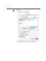
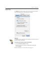
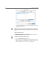
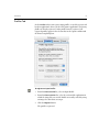
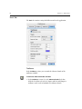
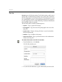
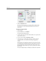
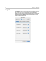
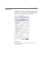
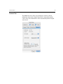
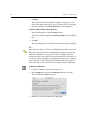
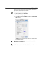
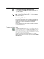
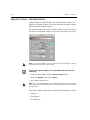
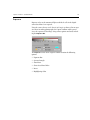
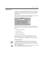
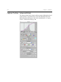
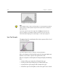
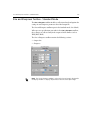
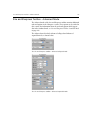
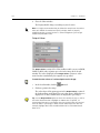
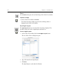
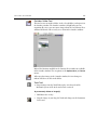
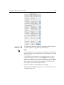
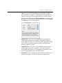
Capture Toolbox - Standard Mode
4.
137
If you save an image, the neutral setting is retained and is active
whenever the picture is open, unless you manually change it.
Gray Balance Setting List
The list in the Gray Balance section contains factory-set settings that you
can apply to an image. There are settings for different Leaf camera backs
and for various lightings.
To select a gray balance setting:
¾ Select a setting from the list and evaluate the results on the screen.
Send to Shoot Setup
The Send to Shoot Setup option retains the current Gray Balance settings
for subsequent shots.
To save the Gray Balance settings for a future shoot:
¾ After setting the Gray Balance for your image, click the Send to Shoot
Setup button.
The Shoot Setup dialog box is automatically updated.
Tip: Save your settings in the Shoot Setup dialog box under a setup name.
These settings can be deleted later, if you find they are not necessary to your
work.
138
Chapter 5 – Toolboxes
Develop Curve
A develop curve is the digital equivalent of the development laboratory.
For example, you can develop an image with more or less contrast by using
a digital ‘push and pull’ type process that is similar to that used in the
analog film lab.
Simple pre-defined curves offer a variety of developing processes, allowing
you to control the result in the image and in its display.
Develop Curve section of the Capture toolbox — Standard expanded mode
The Develop Curve section of the Capture toolbox contains the following
options:
•
•
•
•
Auto Develop Curve button
Develop Curve List
Brightness and Contrast
Send to Shoot Setup button
The Develop Curve section of the Capture toolbox can be used in a
collapsed or expanded view. See Collapsed and Expanded Sections on
page 127 for information about switching from one mode to the other.
Auto Develop Curve
The Auto Develop Curve button modifies the current develop curve,
according to the characteristics of the captured image. The automatic
option creates a curve with reasonable contrast keeping the details in the
shadow and highlight areas.
Note: The Auto Develop Curve option provides a good result only if the image
is exposed correctly. If not, the image can look noisy or flat.
Capture Toolbox - Standard Mode
139
To use the Auto Develop Curve option:
¾ Click the Auto Develop Curve button.
The current curve is given the same name as the open image and
appears in italics. If you save the image, the new curve is automatically
saved with the image.
You can use the Auto Develop Curve option on a specific area of the image
by first cropping the image and then clicking the Auto Develop Curve
button. For information about cropping the image, see Crop on page 111
and Crop on page 121.
Tip: The Auto Develop Curve can be very useful when applied to uncontrolled
lighting situations since the default factory-set curves are created for specific
dynamic range images. The Auto Develop Curve automatically ‘pushes’ the
more detail-rich areas of the image.
Develop Curve List
The list in the Develop Curve section contains factory-set curves that you
can apply to an image.
If you manually correct a develop curve using the Brightness or Contrast
options, the modified curve is given the same name as the open image and
appears in italics. If you save the image, the new develop curve is
automatically saved with the image.
To select a develop curve to apply to your image:
¾ Select a curve from the list and evaluate the results on the screen.
You can locally monitor the effect of the develop curve you have selected by
using the floating RGB densitometer located on the bottom bar of the
Detail window.
Tip: Use the develop curves provided with the application for images that suit
their dynamic ranges. It is usually preferable to set your lighting to a fixed,
appropriate develop curve rather than correcting the curve to suit your lighting.
140
Chapter 5 – Toolboxes
Brightness and Contrast
The Brightness and Contrast options allow you to develop a captured
image in a way similar to using push and pull film processing in analog
photography. Digital brightness and contrast controls, however, enable
you to experiment until the ideal result is obtained.
The Brightness and Contrast option is a final optional step in the
preparation of your image. These controls allow you to substantially
improve some captures with simple adjustments.
To adjust the brightness of an image:
¾ Increase or decrease the brightness by moving the Brightness slider to
the right or left, or by changing the numeric value in the box beside the
Brightness slider. The value can range from -0.5 to +0.5 f-stops, with 0
being the central value.
The brightness of the image in the Display windows changes
accordingly. The numeric value in the box indicates the exact position
on the slider (from -0.5 to +0.5, with 0 being the central value). The
modified develop curve is given the same name as the open image and
appears in italics. If you save the image, the new develop curve is
automatically saved with the image.
The change in brightness is similar to increasing or decreasing
exposure, often referred to as exposure compensation.
To adjust the contrast of an image:
¾ Increase or decrease the contrast by moving the Contrast slider to the
right or left, or by changing the numeric value in the box beside the
Contrast slider. The value can range from -0.5 to +0.5 f-stops, with 0
being the central value.
The contrast of the image in the Display windows changes accordingly.
The numeric value in the box indicates the exact position on the slider
(from -0.5 to +0.5, with 0 being the central value). The selected develop
curve is given the file name of the open image.
The change in contrast is similar to increasing or decreasing the
exposure range of the film, resulting in lesser or greater contrast.
Tip: It is preferable to create a proper exposure using your lighting system, and
to perform only fine adjustments using the Brightness and Contrast options.
This way, you can achieve the best possible image quality.
Capture Toolbox - Standard Mode
141
Send to Shoot Setup
The Send to Shoot Setup option retains your current develop curve for
subsequent shots.
To save the Gray Balance settings for a future shoot:
¾ After setting the gray balance for your image, click the Send to Shoot
Setup button.
The Shoot Setup dialog box is automatically updated.
Tip: Save your current photo shoot settings in the Shoot Setup dialog box under
a setup name. These settings can be deleted later, if you find they are not
necessary to your work.
142
Chapter 5 – Toolboxes
Capture Toolbox - Advanced Mode
The Advanced mode of the Capture toolbox contains additional tools and
options which are described in this section. For information about the
tools and options which appear also in the Standard mode, see Capture
Toolbox - Standard Mode on page 130.
Capture Toolbox - Advanced Mode
143
The Capture toolbox Advanced mode contains the following sections:
•
•
•
•
•
Histogram
Spot tool sample
Exposure
Gray Balance
Develop Curve
Histogram
The histogram is a graphical representation of the exposure data (pixels at
each intensity level) in a captured image. It displays the overall pixel
distribution of the image.
The histogram is read via the x-axis, which is a scale of f-stop values
ranging from +3 f-stops to -8 f-stops. These numbers represent relative
exposure of the image, in f-stops. Zero is the f-stop at the midpoint of the
scale and is equivalent to an 18% reflectance value. The width of the
histogram represents the range of f-stops in the image. The distribution of
pixels at the different exposure levels in the image in terms of highlight,
shadow and midtone values are represented in the histogram by a shaded
area above the x-axis.
You can use the histogram to view changes you make to the exposure and
lighting of the scene. For example, by looking at the histogram, you can
determine if your image is flat, high-key, low-key, and how much
catchlight area you have captured. You can then make exposure or lighting
adjustments, and view the adjustments in the image not only in one of the
display windows but more precisely via the data in the histogram.
The histogram enables you to quantitatively assess your image in terms of
exposure. It is a tool that you can use continually throughout your photo
session, to verify that your shots are correctly exposed.
Note: The histogram shows the 16-bit capture data. This data does not change
when manual digital adjustments are made to the develop curve. Only new shots
with changed lighting or exposure settings will produce a different histogram.
144
Chapter 5 – Toolboxes
How to read the histogram:
Using the histogram as a light meter at each point of the image
•
The shape of the histogram illustrates the key type or the tonal range of
the image.
Histogram of a full tone range image
Histogram of a low-key image
Capture Toolbox - Advanced Mode
145
Histogram of a high-key image
•
The position of the histogram on the horizontal axis reflects the
exposure of the image. Images with effective lighting contrast will
normally be spread across from the lightest to the darkest areas.
A properly exposed image has a highlight area that begins at +2 on the
histogram. This leaves an adequate range (between +2 and +3) for any
shiny elements (such as catchlight) in the image.
Histogram of an over-exposed image
Histogram of an under-exposed image
146
Chapter 5 – Toolboxes
Histogram of a well-exposed image
Tips:
If the histogram shows a lack of sufficient light, it is recommended to reshoot at
a better exposure. Under-exposed images do not respond well to subsequent
digital processing.
If you crop a specific area of the image with the Crop tool (located in the
Overview window), the histogram displays the data of this area. For more
information about cropping, see Crop on page 111 and Crop on page 121.
Spot Tool Sample
The Spot tool provides an indication of the relative exposure of the selected
spot on the histogram.
The relative exposure value (in f-stops) of a selected color point
If the selected point is a black and white point, the histogram displays one
black line, at the relative exposure value point on the x axis.
If the selected point is a colored point, the histogram displays the following
lines:
•
•
•
•
A short red line representing the red channel of the spot
A short green line representing the green channel of the spot
A short blue line representing the blue channel of the spot
A black line represents the lightness value of the spot if it were neutral.
Capture Toolbox - Advanced Mode
147
The numeric color values of this point are shown below the histogram in
Raw (16-bit RGB), RGB (8-bit RGB), or Lab units.
To change the unit:
¾ From the list, select one of the unit options.
To use the Spot tool:
1.
In the Detail window, click the Spot
tool.
2.
In the Detail window, click the point on the image that you want to
measure.
The histogram displays 4 lines (black, red, green and blue) and the
relative exposure value of the selected color point.
If the point you selected in step 1 is black and white, the histogram
displays one black line and the relative exposure value of the selected
point.
The color values of this spot are also displayed in the spot sample.
148
Chapter 5 – Toolboxes
.
Tips:
If you require specific points in the captured image to include detail, they must
be well exposed. With the Spot tool you can control into which exposure zone
each point falls and ensure that you obtain the results you require.
The Spot tool enables you to easily calculate the exposure ratio between the
highlight and shadow areas of the image.
In most cases, the ideal value for the brightest areas in the image detail should
be approximately +2 f-stops between 240 to 248 sv (system values) in Capture
RGB (8-bit) color.
Exposure
Exposure refers to the amount of light that the photo cells in the digital
camera back have been exposed to. Using the same reference scale (that is,
f-stops) as in traditional photography, the exposure options in the Capture
toolbox enable you to assess the exposure of your image using several
different tools.
The Exposure section of the Capture toolbox Advanced mode contains the
following options:
•
•
•
•
•
•
Tone Range Highlighting button
Auto Meter
Show Under
Show Over
Invert
Highlighting Color button
Capture Toolbox - Advanced Mode
149
Tone Range Highlighting button
The Tone Range Highlighting button enables you to manually select a
range on the histogram. Areas of the displayed image that fall in this range
are highlighted in the Overview and Detail windows.
To use the Tone Range Highlighting button:
1.
Click the Tone Range Highlighting button.
2.
Click and drag the mouse horizontally on the histogram to select the
range you want to highlight.
Image areas that fall in the selected histogram range are highlighted in
the Overview and Detail windows.
Note: The area on the image is highlighted with the color selected in the colorhighlighting patch. For more information see Highlighting Color button on
page 135.
Auto Meter
The Auto Meter indicates the difference (in f-stops) between the ideal
overall exposure for a standardly lit image and your actual image exposure
shown by the Exposure Pointer on the Exposure Bar. This information is
helpful in determining whether or not the current image exposure levels
are appropriate for the image you have captured.
The overall exposure of the image is represented by digits, with 0.0
indicating an even exposure, a negative number indicating an underexposure and a positive number indicating an over-exposure.
Show Over/Show Under
The Show Under and Show Under options highlight the areas of the image
that are over-exposed or under-exposed, displaying the values on the
Exposure Bar and highlighting these areas of the image in the display
windows.
This information is helpful in determining how much of and in what areas
your image is over-exposed or under-exposed. Over-exposed or underexposed areas may lack image detail and may not respond well to
subsequent digital processing.
150
Chapter 5 – Toolboxes
To view the over-exposed or under-exposed areas of the image:
1.
Make sure that the Overview window is open.
2.
In the Exposure section of the Capture toolbox, select the Show Over
or Show Under check box, or both.
The corresponding values in the image are indicated on the Exposure
Bar by a band of highlighting color at the left end of the f-stop scale. In
the Display window, those areas of the image that are over- and/or
under-exposed are highlighted in the defined highlighting color.
Note: The highlighting color is defined by the user. (See Highlighting Color
button on page 135).
Tip: Use Show Under and Show Over to assess the exposure range within
your image and thus to guide you as to what lighting changes or what different
exposure settings (such as a change in aperture or exposure time) you may want
to make in order to capture your image with the best quality.
The dynamic range between the over-exposed and under-exposed highlighted
areas is approximately 5 f-stops.
Invert
The Invert option works in conjunction with the Show Over and Show
Under options. It enables you to view and assess the areas of your image by
applying the highlighting color to all areas that are not selected by the
Show Over and/or Show Under options. Your image is displayed with
these inversions in the Display windows and on the Exposure bar.
To use the Invert option:
1.
Make sure that the Overview window is open.
2.
In the Exposure section of the Capture toolbox, select the Show Under
and/or Show Over check box(es).
3.
Click Invert.
All areas of your image which are not under-exposed and/or overexposed are displayed in the Display windows in the highlighting
color.
The Exposure Bar displays a band of highlighting color in the f-stop
range between under-exposure and over-exposure.
Capture Toolbox - Advanced Mode
151
Tip: Use the Invert option to view details in the areas of the image that are
over-exposed or under-exposed and which are masked when using the Show
Over and Show Under options.
Highlighting Color Button
With the Highlighting Color button, you can select the type of highlighting
color that you want to indicate over-exposed or under-exposed areas in
your image, when using the Show Under, Show Over and Invert options.
The button itself takes on the color that you select. There is a variety of
color types and palettes to choose from.
To select a color for under and over exposed areas in your image:
1.
In the Exposure section of the Capture toolbox, click the highlighting
Color button.
The Highlighting Color dialog box opens.
2.
In the Highlighting Color dialog box, select the color that you want to
use in the display of over-exposed and under-exposed areas of your
image.
3.
Click OK.
The Highlighting Color dialog box closes. The color of the
Highlighting Color button changes to the selected color. The selected
color is applied when you use the Show Under, Show Over, and Invert
options.
Tip: Choose a color different from the dominant ones in your captured image
to avoid confusion between the highlighting color mask and your image data.
Gray Balance
With film, color bias in light source and film emulsion can be corrected
using color correction filters. In digital capture, neutrality is achieved with
the Gray Balance option, usually in combination with a neutral-colored
surface in the scene.
152
Chapter 5 – Toolboxes
The Advanced mode contains the following options:
•
•
•
•
•
•
•
Gray Balance Setting List
Image Neutral
Shadow/Highlight Neutral
Cast Controls
Send to Shoot Up
Delete
Save
Gray Balance Setting List
The list in the Gray Balance section contains factory-set settings that you
can apply to an image. There are settings for different Leaf camera backs
and for various lightings.
To select a gray balance setting:
¾ Select a setting from the list and evaluate the results on the screen.
Image Neutral
The Image Neutral option is used to balance the image prior to evaluating
colors. This option reads the point that you choose in your image to be a
neutral point (for example, an 18% gray card or another neutral point in
the image) and automatically makes it neutral. The RGB values of this
neutral point are identical.
The Image Neutral option is very useful for ensuring consistent,
predictable results in your work. As you would use a gray card in analog
photography or the white balance option on a video camera, use the Image
Neutral option before you proceed with any adjustments to the image.
Capture Toolbox - Advanced Mode
153
To set a neutral point for an image:
1.
Include a gray patch in your image, such as the one provided by Leaf or
the Kodak Q14 grayscale. Position the patch in the center of your
composition, making sure it receives light from the different light
sources and is not in a shadow or highlight area.
2.
Click the Image Neutral button.
3.
Pick a point on the gray patch or a gray color in one of the
components of your image.
4.
If you save an image, the neutral setting is retained and is active
whenever the picture is open, unless you manually change it.
Notes:
If you save an image, the neutral setting is retained and applied whenever the
image is opened. To change the neutral setting, you must manually change the
neutral point.
Image Neutral should be used before other options, for the most logical
workflow. For example, if you set non-zero Color Cast values, and then click
Image Neutral, all the Color Cast values return to a 0 value when the Spot tool is
used. See Cast Controls on page 154.
Tips:
Image Neutral is very important when your end result is a printed reproduction.
Each capture must be identical in terms of the neutral value in order to adjust for
such variables as flash intensity, light color temperatures, and so on. It is often
useful to place a gray card permanently in each image, outside of the desired
crop frame. It can then be used to balance each image individually.
To locate an appropriate neutral point, use the Spot tool then analyze the color
values and histogram color lines of the selected spot (the closer the lines are to
each other, the more appropriate the spot). Next, click the Image Neutral
button and click in the selected spot. The lines in the histogram merge into one
line and the color values become identical.
Shadow/Highlight Neutral
The Shadow/Highlight Neutral options enable you to achieve a perfect
neutral setting along the gray scale. These two tools complement the Image
Neutral button and provide you with three neutral points (two end points
and a midtone point).
The Shadow Neutral button removes all cast color in the shadow area.
The Highlight Neutral button removes all cast color in the highlight area.
154
Chapter 5 – Toolboxes
To automatically set the shadow/highlight neutral points of the
image:
1.
Click the Shadow Neutral and/or the Highlight Neutral button.
2.
In the Detail window, click the shadow (or highlight) point you want
to set as a neutral point.
The colors of the image change accordingly.
Note: Using the Image Neutral button after setting the shadow and/or
highlight neutral points, resets the shadow and/or highlight neutral points.
Always use the Image Neutral button first.
Tip: Using the Image Neutral option is usually sufficient for achieving a
balanced image. Use the Shadow/Highlight Neutral option only when your
image has a high dynamic range and you need to make sure that specific
elements of the image (such as white elements) do not have a color cast.
Cast Controls
The Cast Controls option is used to add or reduce the color cast of the
image for creative purposes.
To change the color cast of the image:
¾ Click the arrows of each color values to reach the required cast.
Tip: Using the Cast Controls option before setting the Image Neutral point
and/or shadow and/or highlight neutral points, is ineffective since the Image
Neutral option resets the color cast to zero. Always set the Image Neutral
point first.
Delete
Delete is used to delete a Gray Balance setting. You cannot delete a
factory-set setting, or a custom setting that is currently in use.
To delete a Gray Balance setting:
1.
From the Delete menu, select the Gray Balance setting you want to
delete.
An Are you sure....? message is displayed.
2.
Click OK.
Capture Toolbox - Advanced Mode
155
Save
Save is used to save a Gray Balance setting under a new name.
To save a Gray Balance setting:
1.
In the Gray Balance section, click Save.
2.
In the dialog box that appears, type a name for the setting and click
OK.
Note: You cannot change a factory-set setting or overwrite it.
Send to Shoot Setup
The Send to Shoot Setup option retains your current Image Neutral, and
Highlight/Shadow Neutral settings for your subsequent shots.
To save your Neutral settings for a future shoot:
¾ After setting the Neutral settings for your image, click the Send to
Shoot Setup button.
The Shoot Setup dialog box is automatically updated.
Tip: Save your current photo shoot settings in the Shoot Setup dialog box under
a setup name. These settings can be deleted later, if you find they are not
necessary to your work.
156
Chapter 5 – Toolboxes
Develop Curve
The develop curve is a graphical representation of the mapping between
the 16-bit capture data and the 8-bit output data. The curve is displayed on
the histogram and enables you to make the translation between the capture
data and the output data.
The horizontal axis represents the light values in the scene, from shadows
to highlights. The vertical axis represents the light values on the monitor
(or the ink values in print) in sv units (system values) representing output
intensity. The curve behaves in a similar way to a film characteristic curve,
translating scene exposure to film density.
Manipulating the develop curve is the digital replacement of manipulating
the processing in your developing laboratory. As with analog films you can
develop your image with more or less contrast using the push and pull
process.
Simple pre-defined curves offer a variety of ‘films’ and developing
processes, allowing you to control the result on the display.
Note: To achieve a good result, it is very important to adjust the lighting and
exposure before approaching the develop curve. The develop curve should be
used to make small adjustments to enhance the captured image. As in analog
photography, first you ensure the best exposure, then you choose the
development process if changes to the resulting image as required.
Capture Toolbox - Advanced Mode
157
The develop curve has five control points:
•
Shadow point—Represented by the black dot on the develop curve.
This point indicates the darkest value at which you still see texture and
detail in the output image. Pixels with values smaller than the value of
the shadow point lose details. The recommended output value for
areas with darkest shadow detail should be greater than 10 sv.
•
3/4 tone point—The midpoint between the Shadow point and
Midtone point.
•
Midtone point—Represented by the gray dot on the develop curve.
This point controls the contrast and brightness in the parts of the
image between the shadow and highlight ranges. Values change
gradually away from the Midtone toward the highlight and shadow
point. By moving the Midtone point left or right you can make
Midtone values darker or lighter.
For an ideal exposure, the Midtone output value for an 18% gray card
should be 127 sv.
•
1/4 tone point—The midpoint between the Midtone point and the
Highlight point.
•
Highlight point—Represented by the white dot on the develop curve.
This point indicates the brightest value at which you still see texture
and detail in the output image. Pixels with values greater than the value
of the highlight point lose details. The recommended output value for
areas with brightest highlight detail should be less than 248 sv.
158
Chapter 5 – Toolboxes
To change the curve:
¾ To move an individual point, press ALT and then click and drag it.
¾ To move an end point (Shadow or Highlight point), maintaining the
shape of the curve, click and drag the end point.
All points move except the other end point.
¾ To move a Midtone point and maintain the end points while
restricting the 3/4 tone point and the 1/2 tone point to their
mid-distance positions, click and drag the Midtone point.
All points move except the two end points.
Tip: You can click on any point and then use the keyboard arrows to move it.
The Develop Curve section contains the following options:
•
•
•
•
•
•
•
•
•
•
Auto Develop Curve button
Develop Curve list
Brightness and Contrast
Shadow/Highlight Point buttons
Show Shadows
Show Highlights
Levels
Send to Shoot Setup button
Delete
Save
Auto Develop Curve
The Auto Develop Curve button modifies the current develop curve,
according to the characteristics of the captured image. The automatic
option creates a curve with reasonable contrast keeping the details in the
shadow and highlight areas.
Note: The Auto Develop Curve option provides a good result only if the image
is exposed correctly. If not, the image can look noisy or flat.
Capture Toolbox - Advanced Mode
159
To use the Auto Develop Curve option:
¾ Click the Auto Develop Curve button.
The current curve is given the same name as the open image and
appears in italics. If you save the image, the new curve is automatically
saved with the image.
You can use the Auto Develop Curve option on a specific area of the image
by first cropping the image and then clicking the Auto Develop Curve
button. For information about cropping the image, see Crop on page 111
and Crop on page 121.
Tip: The Auto Develop Curve can be very useful when applied to uncontrolled
lighting situations since the default factory-set curves are created for specific
dynamic range images. The Auto Develop Curve automatically “pushes” the
more detail-rich areas of the image.
Develop Curve List
The list in the Develop Curve section contains factory-set curves that you
can apply to an image.
If you manually correct a develop curve, the modified curve is given the
same name as the open image and appears in italics. If you save the image,
the new develop curve is automatically saved with the image.
To select a develop curve to apply to your image:
¾ Select a curve from the list and evaluate the results on the screen.
You can locally monitor the effect of the develop curve you have selected by
using the floating RGB densitometer located on the bottom bar of the
Detail window.
Tip: Use the develop curves provided with the application for images that suit
their dynamic ranges. It is usually preferable to set your lighting to a fixed,
appropriate develop curve rather than correcting the curve to suit your lighting.
Brightness and Contrast
The Brightness and Contrast options allow you to develop a captured
image in a way similar to using push and pull film processing in analog
photography. Digital brightness and contrast controls, however, enable
you to experiment until the ideal result is obtained.
160
Chapter 5 – Toolboxes
The Brightness and Contrast option is a final optional step in the
preparation of your image. These controls allow you to substantially
improve some captures with simple adjustments.
To adjust the brightness or contrast of an image:
¾ Increase or decrease the brightness or contrast by changing the
numeric value in the box. The develop curve on the histogram changes
accordingly.
The change in brightness is similar to increasing or decreasing
exposure, often referred to as exposure compensation.
The change in contrast is similar to increasing or decreasing the
exposure range of the film, resulting in lesser or greater contrast.
Note: The Brightness and Contrast options are not limited to ± 0.5 f-stops as
in the Standard mode. Nevertheless, it is not recommended to make drastic
changes in brightness and contrast. It is preferable to create a proper exposure
using your lighting system, and to perform only fine adjustments using the
Brightness and Contrast options. This way, you can achieve the best possible
image quality.
Shadow/Highlight Point Buttons
The Shadow Point and Highlight Point options enable you to set a selected
point as the Shadow or Highlight point of the develop curve. This point
receives the default system value for Shadow or Highlight, accordingly.
Note: To set the default system value for the Shadow and Highlight points, from
the File menu, select Preferences. In the Preferences dialog box, on the Tools
tab, in the Output Levels section, type the values in the Highlight and Shadow
boxes.
Tip: The Shadow and Highlight points are critical for producing high quality
offset prints. The highlight point is related to the lowest amount of ink that the
printer can lay down on paper, and the shadow point is related to the highest
amount of effectively printable ink. If you are printing to offset, you should get
the optimal values for these points from your printer.
Show Highlights/Show Shadows
After you select a develop curve, the Show Highlights option highlights the
light areas of the image that are above the highlight point limit and will
have no details in print. These areas are highlighted in both the histogram
and the display windows. The Show Shadows option similarly highlights
dark areas on the image that are beyond the shadow point.
Capture Toolbox - Advanced Mode
161
To view these areas:
¾ After selecting a develop curve, select the Show Highlights or the Show
Shadows check box, or both.
The light areas and/or dark areas (with no print details) of the image
are highlighted in the histogram and in the display windows.
Note: The highlighting color in the display windows is defined by the user. (See
Highlighting Color button on page 135).
Levels
The Develop Curve Levels dialog box displays the value of each of the five
control points on the histogram.
Values are shown in Capture (16-bit) system values and Develop (8-bit)
system values.
If you change the Capture value of a control point, the point moves along
the x-axis of the histogram.
If you change the Develop value of a control point, the point moves along
the y-axis of the histogram.
Important: The Levels option should be used only if you know the exact
required values of each point.
162
Chapter 5 – Toolboxes
Delete
Delete is used to delete a develop curve. You cannot delete a factory-set
curve, or a custom curve that is currently in use.
To delete a develop curve:
1.
From the Delete menu, select the develop curve you want to delete.
An Are you sure....? message is displayed.
2.
Click OK.
Save
Save is used to save a develop curve under a new name.
To save a develop curve:
1.
In the Develop Curve section, click Save.
2.
In the dialog box that appears, type a name for the curve and click OK.
Note: You cannot change, overwrite or delete a factory-set curve.
Send to Shoot Setup
The Send to Shoot Setup option retains your current Develop Curve
section settings for your subsequent shots.
To save your settings for a future shoot:
¾ After selecting a develop curve for your image and setting other
parameters in the Develop Curve section, click the Send to Shoot
Setup button.
The Shoot Setup dialog box is automatically updated.
Tip: Save your current photo shoot settings in the Shoot Setup dialog box under
a setup name. These settings can be deleted later, if you find they are not
necessary to your work.
Size and Sharpness Toolbox - Standard Mode
163
Size and Sharpness Toolbox - Standard Mode
The Size & Sharpness toolbox includes a collection of tools and options for
setting size and sharpness parameters for a final output file.
The Size and Sharpness toolbox opens in the Standard mode (the default).
When you save specifications you make in the Size & Sharpness toolbox,
these changes are reflected only in the output 8-bit file format (such as
TIFF, JPEG, EPSF).
The Size & Sharpness toolbox contains the following sections:
•
•
Output Size
Sharpness
Note: The Size & Sharpness toolbox is active only when an image is displayed in
the display windows. It displays all parameters relevant to the open image.
164
Chapter 5 – Toolboxes
To open the Size & Sharpness toolbox in the Standard mode, do one
of the following:
¾ From the Main Toolbar, click the Size & Sharpness button.
¾ From the Window menu, select Size & Sharpness.
¾ Press SHIFT+COMMAND+X.
Note: If the Size & Sharpness toolbox was in the expanded view when you last
closed the application, the Size & Sharpness toolbox opens in the expanded view
when you re-open the application.
Output Size
The Output Size section of the Size & Sharpness toolbox contains options
related to the output size of the image.
The Output Size section works together with the Crop tool of the display
windows. If you crop a certain area of the image with the Crop tool, the
parameters in the Output Size section change accordingly. If you change
the parameters in the Output Size section, the cropped area changes
according to these parameters. The Output Size section displays
information about the output values of the cropped area.
For information about cropping the image, see Crop on page 111 and Crop
on page 121.
Size and Sharpness Toolbox - Standard Mode
165
The following options are found in the Output Size section of the Size &
Sharpness toolbox:
•
•
•
•
•
•
•
•
•
Output Size list
Preview
Send to Shoot Setup button
Res
Width and Height
Scale
File size
Delete
Save
Output Size List
The Output Size list contains four sections:
•
The setting of the image currently displayed in the Overview window
and the Detail window.
•
Factory-set output size settings set according to standard output sizes
and orientations.
If you select a factory-set setting, its specifications determine the
dimensions of the output of your image. A crop (selected area) is
automatically displayed in the detail and overview windows, and the
output parameters change, according to the specified name of the
selection.
•
•
Names of the customized settings that you created.
Name of modified setting. The modified setting is given the same
name as the open image and appears in italics. If you save the image,
the new output size is automatically saved with the image.
166
Chapter 5 – Toolboxes
Preview
The Preview option enables you to see the scaled image in the Detail
window. It gives you a 1/1 display of the image after it has been scaled to its
final dimensions.
To use the Preview option:
¾ After entering your output image parameters, select the Preview check
box.
In the detail window, the image is displayed according to the scale you
selected. On the title bar of the detail window, the name of the image is
follow by the scale value in %.
Tips:
Use Preview to see the effects of the choice you've made in the Scale box. But
remember that a display proof of the printed result requires previewing the
Sharpness settings as well.
You can also activate Preview by selecting Scaled from the View menu or by
pressing ALT+COMMAND+O.
Send to Shoot Setup
After setting the output size for your image by defining crop and output
parameters or selecting it from the Output Size list, you can use the Send
to Shoot Setup button to save these specifications in the Shoot Setup
dialog box for use in the next session shoot.
To save your output size settings for a future shoot:
¾ After setting the output size for your image, click the Send to Shoot
Setup button.
The Shoot Setup dialog box is updated automatically.
Tip: If you think you can reuse your selection settings, use the Send to Shoot
Setup button. You can also save them in the Shoot Setup dialog box under a
setup name. These settings can be deleted later, if you find they are not
necessary to your work.
Size and Sharpness Toolbox - Standard Mode
167
Res
Res (resolution) is the number of pixels per unit of printed length in an
image.
Resolution is usually measured in pixels per inch (ppi) or pixels per
millimeter (ppm).
An image with a high resolution contains more (therefore smaller) pixels
than an image of the same output dimensions with a low resolution.
A high resolution reproduces more detail and subtler color transition,
because it uses more pixels to represent each unit area.
To select a unit of resolution:
¾ From the Unit column of the Res box, select a unit from the list.
To set a resolution:
¾ In the Res box, type an appropriate output resolution for your work
and press ENTER.
Tip: It is recommended to type the resolution prior to the other parameters of
the Output Size section.
It is important to choose a resolution that best suits the output requirements for
your image. For example, if you know that the image will be printed in a
newspaper, you may not need a high resolution. If you know that the image will
become a photographic print or be reproduced in a glossy magazine, you will
require a high resolution for best end results.
168
Chapter 5 – Toolboxes
Width/Height
The final output size of the image is set in the Width and Height boxes.
The Width and Height units can be inch (in), centimeter (cm), pica (a font
size unit), or pixel (pix).
You can manually change these values by entering new values in the boxes
or by dragging the crop line in the Overview or Detail window.
When you set the exact width and height values you change the output size
of the image while the captured (the crop) size stays the same. The scale
value will change accordingly.
If you define a crop with the Crop tool, the values of Width and Height will
be the width and height of the crop using the displayed values of resolution
(Res) and scale (Scale).
If you choose a factory-set setting from the Output Size list, the Height and
Width boxes display pre-determined width and height values for this
selection. These values are locked and cannot be changed.
To select a unit of measurement for width and height:
¾ From the Unit column of the Height and Width boxes, select a unit
from the list.
To set and lock width and height values of the image for output, do
one of the following:
¾ In the Height and Width boxes, type the required values and press
ENTER or press the Lock
button.
¾ In one of the display windows, crop the area that you want to output.
The values in the Width and Height boxes change accordingly.
Note: The dimensions of the crop in the display windows may change.
Tip: If you know the exact values of your output, type and lock them. The scale
is calculated automatically according to your resolution and crop values.
Size and Sharpness Toolbox - Standard Mode
169
Scale
Scale is the dimension of the output image in relation to the dimensions of
the captured image. If your image for output is twice the size of the
captured image, then the scale is 200%.
Scale re-samples the pixels of the image. It removes pixels when scaling
down, and adds pixels when scaling up.
If you change the Scale value, and the Width and Height values are not
locked, the Width and Height values change accordingly. If the Width and
Height values are locked, the selected cropped area changes accordingly.
If you lock the Scale value, and change the Width and Height values, the
crop changes accordingly.
It is important to understand that a high scale value can affect the image,
making it appear blurry or out of focus. Therefore the Scale option must
be used in coordination with the Sharpness option. The Sharpness setting
is directly connected to the Scale value. For more information about the
Sharpness setting, See Sharpness on page 170 and on page 174.
Lock Buttons
The Lock buttons enables you to lock Height, Width, and/or Scale values so
that you can change the unlocked dimensions without affecting those you
have locked.
Each dimension has its own lock button, therefore:
•
•
•
If you lock the Height value, you can only change the Width value.
If you lock the Width value, you can only change the Height value.
If you lock the Scale value, you can change either the Height or the
Width value but only within the specified Scale value of the image.
To lock the size specifications (height, width and or scale):
¾ After specifying the height, width or scale for the output image, click
the Lock button.
The height, width, and/or scale are locked.
File Size
The File Size value gives you the output size of the file in MB (megabytes)
after you set all your output parameters for the image.
170
Chapter 5 – Toolboxes
Delete
Delete is used to delete an Output Size setting. You cannot delete a
factory-set setting, or a custom setting that is currently in use.
To delete an Output Size setting:
1.
From the Delete menu, select the setting you want to delete.
An Are you sure....? message is displayed.
2.
Click OK.
Save
Save is used to save an Output Size setting under a new name.
To save an Output Size setting:
1.
In the Output Size section, click Save.
2.
In the dialog box that appears, type a name for the setting and click
OK.
Note: You cannot change, overwrite, or delete a factory-set setting.
Sharpness
A digital image usually needs some sharpness adjustment to provide the
desired effect in print or other output especially after rescaling.
The Sharpness section enables you to sharpen the edges in the image while
avoiding the sharpening of noise. Sharpening occurs on the borders of
adjoining areas of different levels of brightness. After sharpening, a very
thin contour of a lighter and darker strip emphasizes the border between
different-colored objects.
The Sharpness section of the Size & Sharpness toolbox contains the
following options:
•
•
•
•
Sharpness table list
Sharpness slider
Preview
Send to Shoot Setup button
Size and Sharpness Toolbox - Standard Mode
171
Sharpness Table List
The Sharpness table list includes factory-set and custom tables that you
can apply to an image.
Factory-set table names reflect the characteristics of the table. For example,
a sharpness table suitable for portrait photography.
To use the table list:
¾ From the Sharpness table list, select a table and evaluate the results on
the screen by selecting the Preview check box.
Sharpness Slider
The Sharpness slider enables you to increase or decrease the degree of
sharpness of the image.
To adjust the sharpness of the image:
¾ Increase or decrease sharpness by moving the Sharpness slider to the
right or left.
Preview
The Preview option enables you to see the sharpened scaled image in the
Detail window. This Preview option automatically selects the Preview
check box in the Output Size section of the Size and Sharpness toolbox as
the degree of sharpness depends on the output size.
To use the Preview option:
¾ After selecting your sharpness setting, select the Preview check box.
In the detail window, the image is displayed according to the scale and
sharpness level you selected. On the title bar of the detail window, the
name of the image is follow by the scale value in %.
Tip: You can also activate Preview by selecting Scaled & Sharpened from the
View menu or by pressing COMMAND+G.
Send to Shoot Setup Button
After setting the degree of sharpness for your image, you can use the Send
to Shoot Setup button to save these specifications in the Shoot Setup
dialog box for use in the next session shoot.
172
Chapter 5 – Toolboxes
To save your sharpness settings for a future shoot:
¾ After setting the degree of sharpness for your image, click the Send to
Shoot Setup button.
The Shoot Setup dialog box is updated automatically.
Tip: If you think you can reuse your selection settings, use the Send to Shoot
Setup button. You can also save them in the Shoot Setup dialog box under a
setup name. These settings can be deleted later, if you find they are not
necessary to your work.
Size and Sharpness Toolbox - Advanced Mode
173
Size and Sharpness Toolbox - Advanced Mode
The Advanced mode of the Size and Sharpness toolbox contains additional
tools and options in the Sharpness section. These options are described in
this section. For information about the tools and options which appear
also in the Standard mode, see Size and Sharpness Toolbox - Standard Mode
on page 163.
The Advanced mode includes Advanced collapsed and Advanced
expanded modes, as shown below:
The Size and Sharpness toolbox - Advanced collapsed mode
The Size and Sharpness toolbox - Advanced expanded mode
174
Chapter 5 – Toolboxes
Sharpness
Sharpness Table List
The Sharpness table list includes factory-set and custom tables that you
can apply to an image.
Factory-set table names reflect the characteristics of the table. For example,
a sharpness table suitable for portrait photography.
You can save a new Sharpness table as a custom table that is then available
in the list. For details see Save on page 176.
To use the table list:
¾ From the Sharpness table list, select a table and evaluate the results on
the screen.
Radius
The Radius determines the thickness of the contour produced by the
Sharpness option. The larger the number in the Radius list, the thicker the
contour surrounding the details of the image. The larger the image, the
larger the required radius.
If the image is scaled and you want to modify its Sharpness level, Radius is
the first parameter you should set.
Tip: For portrait photography, use a smaller radius value (smoother sharpness
level) than for still life photography.
Edge Intensity (Highlight & Shadow)
Sharpness is effected by comparing the light intensity of a pixel to its
surrounding area and modifying the pixel accordingly. If the pixel is darker
than its surrounding area, it is darkened even more to achieve a sharper
contrast. If the pixel is lighter than its surrounding area, it is lightened even
more to achieve a sharper contrast. If the light intensity of the pixel is the
same as that of its surrounding area, no action is taken.
The Edge Highlight and Shadow lists enable you to select the degree of
lightening or darkening of the pixels.
Size and Sharpness Toolbox - Advanced Mode
175
If the image is not scaled and you want to modify its level of sharpness,
Edge Highlight and Shadow should be the first parameters you set.
Tips:
For high dynamic range images, both Highlight and Shadow should be set to
the same level.
With low-key images, increase the Highlight edge more than the Shadow
edge.
With high-key images, increase the Shadow edge more than the Highlight
edge.
Filters
The Filters option defines the color channel (separation) used as a
reference for image sharpening. Single color filters (Red, Green, or Blue)
result in some colors being sharpened, while All sharpens all colors. When
using a single color filter, all the RGB channels are sharpened according to
the variations in brightness of the selected filter channel, while All
sharpens each channel according to the variations in that channel.
When the image contains a specific color that is dominant, or when a
specific element needs to be emphasized, use the filter that corresponds to
that color.
For most images the Green filter creates a pleasing enhancement. Portrait
images may be improved by use of the Red filter.
Use the All or Red-Green filters with a multi-color image that contains a
many details.
Grain
The Grain option prevents the enhancement of smooth areas which would
otherwise acquire a grainy look. Grain is reduced by decreasing sharpness
according to the nature of the surrounding area. Flat areas are strongly
reduced, texture and edges are not.
Two separate parameters control grain reduction:
Range—Refers to the amount of pixel variation in the surrounding area
below which the effect is considered grain, and above which it is
considered texture or edges. The higher the range, the larger the differences
that are considered grain.
176
Chapter 5 – Toolboxes
Reduction—Determines the amount of sharpness reduction performed on
the area that is considered grain. None leaves the sharpness intact while
Max reduces it completely.
Delete
Delete is used to delete a Sharpness table. You cannot delete a
factory-set table, or a custom table that is currently in use.
To delete a Sharpness table:
1.
From the Delete menu, select the table you want to delete.
An Are you sure....? message is displayed.
2.
Click OK.
Save
Save is used to save a Sharpness table under a new name.
To save a Sharpness table:
1.
In the Sharpness section, click Save.
2.
In the dialog box that appears, type a name for the table and click OK.
Note: You cannot change, overwrite, or delete a factory-set table.
Color Toolbox
177
Color Toolbox
Overview of Color Management
The method employed in the Color toolbox to maintain color quality is
ICC color management. ICC color management provides a means for
linking capture, display and printing devices to a universal color standard
to maintain color fidelity throughout the workflow.
In order to understand the usefulness of color management and the ICC
standard, the following background information is useful:
•
Human Judgement of Color
The human eye, of the average person, perceives a fairly similar,
definable, measurable spectrum of colors. Every person has color
memory for colors very familiar to them (such as the blue of the sky and
the green of grass) but when a person compares colors in two images,
many elements interfere with color perception, such as ambient
lighting, placement of objects in the scene, and so on. Thus, it is
important to view and judge color in consistent and standard
conditions. For example, it is advisable to view the monitor in subdued
lighting or under a hood. Printed copy should be viewed in a lightbox.
•
Machine Reproduction of Color
Each element of a scene is given an RGB value by the capture device. If
those RGB values were sent directly to a printer or monitor, there is no
reason to expect the displayed result to reproduce the original color.
Each device has a different technology, different color medium, and so
on. Faithful color reproduction requires the colors produced by one
device to be converted to the color ‘space’ of another device. It is of
utmost importance that the devices be correctly calibrated.
Uncalibrated devices do not represent even their native color correctly.
•
ICC (International Color Consortium)
The International Color Consortium (ICC) is a body of graphic arts
companies dedicated to creating specifications and standards for the
management of color in images.
178
Chapter 5 – Toolboxes
•
ICC Profile
The ICC profile is a table that links the color of a device to the universal
color standard employed by the ICC. Thus, color from the camera may
be converted to the color of a display or print device via the universal
color standard. The camera ICC profile converts color to the universal
standard and the print or display device converts from the universal
standard to its device color. The same perceived color is maintained
throughout.
•
Lab in ICC
The universal color space employed by the ICC is Lab color. L is
luminance and a and b are Red/Green and Blue/Yellow channels
respectively.
A profile thus enables translation to and from a device-specific RGB
color definition and a Lab color definition.
•
Color Gamut
The color gamut is the range of Lab values that a device is able to
produce. A device’s gamut is measured by displaying or printing a file
with all possible combinations of R, G and B. The resulting range of
colors is the device’s gamut. In order to compare and understand the
color gamut, we represent it in the units of the universal color standard
- Lab. The gamuts of different devices may include or intersect each
other. In general, the larger the gamut of a device, the better color it
reproduces.
•
RGB Working Space
Adobe Photoshop has introduced the concept of RGB Working Space
for its software needs. It is a virtual monitor space representing an ideal
device which includes many more colors than can be displayed on a real
monitor. The key requirement is that the RGB Working Space includes
the colors that can be printed on paper. For example, Adobe RGB
(1998), Adobe’s recommended RGB Working Space, contains the
gamut of most offset printing processes.
•
Camera RGB
The RGB produced by each Leaf camera back is referred to as Camera
RGB. The gamut of any Leaf Camera RGB is larger than any RGB
working space. The closest published RGB working space is Kodak
ProPhoto RGB.
Color Toolbox
179
Color Toolbox
The Color toolbox is a dialog box that contains various settings and
options that enable you to manage the colors of your image and achieve
quality and consistency.
The Color toolbox contains the following options:
•
•
•
•
•
•
Disable ICC Color Management
Input
Output
Display
Output Values
Send to Shoot Setup
To open the Color toolbox, do one of the following:
¾ From the Main Toolbar, click the Color toolbox button.
¾ From the Window menu, select Color.
¾ Press SHIFT+COMMAND+C.
Note: The information in the Color toolbox pertains only to the open image.
Disable ICC Color Management
Disable ICC Color Management refers to the option to disable the use of
ICC Color Management. Without ICC Color Management, the output file
for the image is an RGB file that conforms to the camera RGB color space.
This option is used to create the color target required by profile creation
programs. After creating the input profile, this option must be reactivated.
180
Chapter 5 – Toolboxes
To disable the use of ICC Color Management:
¾ In the Color toolbox, select the Disable ICC Color Management check
box.
ICC Color Management is not used in creating the output file of the
image.
Notes:
When you select the Disable ICC Color Management check box, the Input and
Output lists become unavailable.
After a new Input profile is created, it must be registered. See Preferences on
page 47.
Input
The Input list contains a list of Camera Profiles. There are several
factory-set profiles for each type of camera back. Each profile has specific
characteristics. The Camera Profiles are recognizable according to the
following elements in their names:
•
•
•
•
NS—Normal saturation
HS—High saturation
LS—Low saturation
W—Warm
The Camera Profile you select determines the color values of your captured
image.
For example, Valeo 22 Product HS is a camera profile that produces a
warm, highly saturated image. This is the recommended Input Profile for
portraiture with the Leaf Valeo 22 camera back.
You can add your own profiles by registering them in the Preferences
dialog box (on the Profiles tab). For information see Profiles Tab on
page 51.
To select a camera profile:
¾ From the Input list, select a camera profile.
The colors of the image adjust to comply with the parameters in the
camera profile you select.
Color Toolbox
181
Output
The Output list contains a list of output profiles. There are several
factory-set profiles for each output device.
The Output list contains output profiles (RGB or CMYK) and RGB
Working Spaces for the image. An RGB Working Space is a virtual device
often used in color management. It is easier and more convenient for most
users to work in an RGB color space, rather than in the Lab color space. For
this reason, an RGB Working Space is used when there is work remaining
to be done on an image. An RGB Working Space always has a profile
associated with it. For more information, see Overview of Color
Management on page 177.
To select an Output Profile or RGB Working Space for an image:
¾ From the Output list, select an Output Profile or RGB Working Space.
The image file for output is adjusted to comply with the parameters in
the Output Profile or RGB Working Space that you selected.
Tip: Leaf camera backs are devices with large color gamuts. A large color gamut
ensures that most colors can be accurately reproduced when an image is
transferred from one device to another. It is thus advisable to use a large gamut
or “wide” RGB working space when transferring the image to another
application. Examples of wide color spaces are ProPhoto RGB and Adobe RGB.
An example of a narrow color space is RGB.
Display
The Display Profile in the Color toolbox is a non-interactive section. It
displays the name of the Display Profile that you are currently using to
view the open image. You can change the Display Profile via the ColorSync
Control Panel on your Macintosh system.
To change the Display Profile of your Macintosh system:
1.
On the Macintosh, from the Apple menu, select Control Panel then
Monitors.
The Monitor window opens.
2.
Click the Color button.
The Color window opens.
3.
In the ColorSync Profile section, select the profile you want to use for
the display.
182
Chapter 5 – Toolboxes
4.
Close the Color window.
The Display Profile changes according to your selection.
Note: It is highly recommended that you follow the manufacturer instructions
when you calibrate the monitor and specify a Display Profile. A properly
calibrated monitor is essential for the ICC color management system to give
reliable and predictable results.
Output Values
The Output Values section of the Color toolbox enables you to read RGB,
CMYK, or B/W values of points you select in the image in the Detail
window. The values displayed in the Output Values section are values
arrived at after translation by the output device specified.
To read the color values of a selected point on the image:
1.
In the Detail window, click the
2.
Click on a point in the image.
Spot tool.
The color values of this point appear in the Output Values section of
the Color toolbox, under their respective color square. RGB values are
displayed as sv units; CMYK values are displayed as percentages.
Tip: Use the Output Values option to check the neutrality of grays, as well as
the level of detail and color in highlight or shadow areas. In general, it is
recommended that you use this option when you need to know the numerical
values of colors in your image, in order to check and/or adjust the color. For
example, highlight detail values should be below 248 sv and shadow details
above 10 sv.
Color Toolbox
183
Send to Shoot Setup
The Send to Shoot Setup option retains your current color parameters for
subsequent shots.
To save your color parameters for a future shoot:
¾ After setting input and output profiles for your image, click the Send
to Shoot Set up button.
The Shoot Setup dialog box is automatically updated.
Tip: Save your current settings in the Shoot Setup dialog box under a setup
name. These settings can be deleted later, if you find they are not necessary to
your work.
Leaf Video View
Introduction to Video View .............................................................186
Video View Toolbar .........................................................................188
186
Chapter 6 – Leaf Video View
Introduction to Video View
Video View can be used with a Leaf C-Most or Leaf Valeo digital camera
back (without a video adaptor) and with a Leaf Volare, Leaf Cantare, or
Leaf Cantare XY digital camera back (with a video adaptor) when the
digital camera back is attached to certain camera types.
Note: With the Leaf Valeo 11, Leaf Valeo 17, and Leaf Valeo 22 digital camera
backs, a software access key is required.
Video View enables you to see a real-time, video-like image in the Video
View display window of Leaf Capture. Video View has several uses which
are outlined in this introduction.
•
Composition
Viewfinder—Some large format cameras do not include a camera
viewfinder and while using some cameras you may not want to
view the image through the camera’s ground glass or viewfinder.
The Video View window acts as your viewfinder.
Layout—With the Digital Layout function you can create a
composition according to a predefined layout of a previous shoot or
from a custom editor.
•
Focusing
Digital Focus—On view cameras, it is often inconvenient to place
and remove the viewfinder screen. Focusing directly on the sensor
with Video View enables a high degree of precision with relative
ease.
Accuracy—If you use the ground glass of the camera to focus, when
you remove or slide out the back, you may inadvertently move the
camera and thus lose the accuracy of the focus. When using the
Video View window as the viewfinder, you do not encounter this
type of problem.
Depth of Field—Before a capture, you can check the depth of field
in the Video View window. In a camera with an electronic shutter,
stopping-down is automatic.
Video View Window
187
Video View Window
The Video View window contains an upper information bar, a toolbar and
a display area.
To activate Video View:
1.
Connect (making sure to use a video adaptor, if required, with the
camera and digital camera back you are using).
2.
Activate Video View with one of the following actions:
3.
a.
On the main toolbar, click the Video View button.
b.
Press SHIFT+COMMAND+L.
c.
On the Window menu, select Video View.
Another message appears: Set shutter speed to “B” or “T”
and aperture to wide open.
4.
In the message box, click the Show this message each time check box
if you want the message to appear each time you connect to Video
View.
5.
Click OK.
The Video View window opens.
Notes:
If there is too much light or insufficient light, the image does not appear and the
Video View display area is blue.
If you did not set up the video adaptor correctly, your camera back does not
support the Video View feature or Trigger Mode>Camera on the main menu is
selected, you cannot access Video View.
188
Chapter 6 – Leaf Video View
To close the Video View window, do one of the following:
¾ On the main toolbar, click the Video View button.
¾ On the upper information bar of the video view window, click the red
circle.
Upper Information Bar
The upper information bar displays this information: the Video View
window name and the zoom ratio of 1:1 if the Zoom In function is active.
The information changes automatically in accordance with the image that
is displayed.
Video View Toolbar
The Video View toolbar contains the following tools:
•
•
•
•
•
•
•
•
•
•
•
•
Zoom
Hand
Contrast Meter
Exposure Slider
Pause
Save Digital Layout
Open Digital Layout
Opacity Slider
Show/Hide Layout
Depth of Field
Tilt and Swing
Grid
Video View Window
189
Zoom
The Zoom tool enables you to zoom in to a magnification ratio of 1:1 and
zoom out to a full image display. The zoom ratio 1:1 shows the full
resolution of the sensor and allows you to focus precisely. The 1:1
magnification ratio is not available if you are using a Leaf C-most or a Leaf
Valeo 6 digital camera backs.
To zoom in:
1.
On the Video View toolbar, select the Zoom tool.
2.
Move the Zoom tool to the image area.
A plus sign is displayed on the Zoom tool to indicate the zoom in
function.
3.
Click on the image.
The magnified image is displayed with the selected area at its center.
To zoom out:
1.
On the Video View toolbar, select the Zoom tool.
2.
Move the Zoom to the image area.
A minus sign is displayed on the Zoom tool to indicate the zoom out
function.
3.
While holding down the ALT key, click on the image.
The full image is displayed.
Note: If the Zoom tool is active, all Digital Layout functions are grayed out.
Tip: To see another area of an image when an image is in Zoom display, use the
Hand tool to pan the image.
190
Chapter 6 – Leaf Video View
Hand
With the Hand tool, you can drag an image within the Video View window.
To use the Hand tool:
1.
On the Video View toolbar, click the Hand tool.
2.
Click and drag the image in the Video View window.
Tips:
The Hand tool can be used to pan the image during a Video View Preview if the
image is in Zoom display or the full image does not fit in the display area.
To select the Hand tool, you can also press the space bar on the keyboard.
Contrast Meter
The Contrast Meter measures focus by measuring the contrast in a selected
area. The Contrast Meter aids you in a visual way to achieve the best
possible focus.
To use the Contrast Meter:
1.
On the Video View toolbar, select the Contrast Meter tool.
2.
Select a point on the image that contains a transition in contrast and
on which you want to focus.
The Contrast Meter bar opens.
The numbers displayed at the top of the Contrast Meter are 50/50.
The first number represents the position of the maximum indicator
line on the scale (this number is the highest value achieved since the
current focus point was selected). The second number indicates the
position of the continuous color on the scale (this number represents
the current focus reading). 50 is the starting point for indicating
whether or not the selected point is in or out of focus. The colors on
the Contrast Meter scale range from blue on the lower area of the scale,
through to red in the upper area, and green in the middle area.
Video View Window
191
3.
Focus the camera lens.
a.
The image is out of focus if the continuous indicator color moves
below the maximum indicator line and down the scale. The
indicator line remains at 50.
b.
The image is in focus if the indicator color moves above the
indicator line and up the scale.
c.
The best focus achieved yet is indicated by the position of the
maximum indicator line on the scale.
Note: Each time you click on the image (when the Contrast Meter tool is
active), the point on the image is reset to 50/50 on the Contrast Meter.
To move the Contrast Meter bar to another location on the screen:
¾ Drag the Contrast Meter bar to any location on the screen.
To close the Contrast Meter:
¾ Click the close box in the upper left corner of the Contrast Meter.
Tips:
To change the orientation of the Contrast Meter (for example, to suit a
horizontal or vertical image) click the orientation box at the top right corner of
the Contrast Meter bar.
For best focus results, select a high contrast area which is in a single focal plane.
Do not select the edge of an object with a more distant object behind it.
Exposure Slider
The Exposure Slider enables you to adjust the exposure time via the
application. By using the Exposure Slider, you can obtain the best exposure
for an image display in Video View.
To increase/decrease exposure time:
¾ Click the upper button on the Exposure Slider to increase exposure
and the lower button to decrease exposure.
The image displayed in the Video View window adjusts accordingly.
Note: The greater the exposure time, the longer it takes for the Video View
display to refresh.
192
Chapter 6 – Leaf Video View
Pause
Use the Pause tool to pause the real-time image in the Video View window.
To pause an image:
¾ On the Video View toolbar, click Pause.
The Video View image display is paused and a still image frame is
displayed in the Video View window.
Save Digital Layout
The Save Layout button saves the last Video View image displayed. The
saved file can then be used as a digital layout for future use.
To save a Digital Layout:
1.
On the Video View toolbar, click the Save Digital Layout button.
The Save Video View As dialog box opens.
2.
Type a file name for the digital layout.
3.
Click New.
The digital layout is saved under the filename.
Video View Window
193
Open Digital Layout
The Open Digital Layout button opens the Open dialog box in which you
can open a digital layout to be displayed over the Video View image in the
Video View window.
To use Open Digital Layout:
1.
On the Video View toolbar, click Open Digital Layout.
The Open dialog box is displayed.
2.
Select a digital layout.
3.
Click Choose.
The digital layout is displayed over the Video View image.
Opacity Slider
With the Opacity Slider you can control the opacity of the Digital Layout
over the Video View image. This allows you to view, simultaneously, both
the Digital Layout and the Video View image, regardless of their inherent
brightness or darkness.
To use the Opacity Slider:
1.
Click Digital Layout.
In the Video View window, the Video View image and the Digital
Layout are both displayed at 50% opacity, as if super-imposed.
The indicator line on the Opacity Slider is displayed at the midpoint of
the scale.
194
Chapter 6 – Leaf Video View
2.
Adjust the opacity of the Video View image and the Digital Layout by
clicking the buttons at the top and bottom of the Opacity Slider.
a.
If you click the button at the top of the Opacity Slider, the Digital
Layout is more opaque than the Video View image display. The
indicator on the Opacity Slider moves up to the darker portion of
the scale. If the indicator reaches the top point on the scale, only
the Digital Layout is visible in the Video View window.
b.
If you click the button at the bottom of the Opacity Slider, the
Video View image is more visible than the Digital Layout display.
The indicator on the Opacity Slider moves down to the lighter
portion of the scale. If the indicator reaches the bottom point on
the scale, only the Video View image is visible.
Tip: To change the opacity, you can also slide the indicator up and down the
Opacity Slider.
Show/Hide Digital Layout
With Show/Hide Digital Layout, you can choose to display an open digital
layout over the Video View image or hide it from view.
To show/hide the digital layout:
¾ On the Video View toolbar, select the Show/Hide Digital Layout tool.
If the digital layout is currently displayed, it is hidden when you select
the tool.
If the digital layout is currently hidden, it is displayed when you select
the tool.
Depth of Field
When using Video View, on a camera with electronic aperture control, the
aperture automatically moves to a fully open position. This allows you to
focus more precisely. If you want to check the depth of field when you are
using Video View, use the Depth of Field tool to change the aperture. You
can see the depth of field of the capture in the Video View display window.
To use Depth of Field:
1.
Zoom in on the part of the image you want to check for depth of field.
2.
Check the focus with a fully open aperture.
Video View Window
195
3.
On the Aperture Control Bar of the main toolbar, click the arrows to
move the aperture indicator to the f-stop you require for the capture.
4.
On the Video View toolbar, select the Depth of Field tool.
The aperture adjusts to the aperture indicated on the Aperture Control
Bar.
5.
Check the focus.
6.
Adjust the focus and aperture as required.
For more information about using the Aperture Control Bar on the main
toolbar, see Aperture Control Bar on page 28.
Tilt and Swing
Tilt and Swing is available when a Sinar view camera with a Sinarcam is
connected. Tilt and Swing displays a vertical line on the Video View image
if the sensor is horizontal and a horizontal line on the Video View image if
the sensor is vertical. The line contains a constant number of pixels and is
at a fixed distance from the edge of the image. Using the line as a reference,
you can adjust the tilt and swing position of the camera axes.
To use Tilt and Swing:
1.
On the Video View toolbar, select the Tilt and Swing tool.
A line appears on the image.
2.
Adjust the camera axes using the line as a reference.
To remove the Tilt and Swing line:
¾ On the Video View toolbar, select the active Tilt and Swing tool.
Grid
The Grid tool enables you to view a grid on the image in the Video View
window. The grid is useful for composition and alignment of an image
displayed in the Video View window. You define the grid in the Preferences
dialog box.
To activate the grid:
¾ In the Overview window toolbar, click the Grid tool.
A grid appears on the image in the Overview window.
196
Chapter 6 – Leaf Video View
To remove the grid:
¾ On the Overview window toolbar, click the activated Grid tool.
The grid is removed.
Note: The Grid definition in the Preferences dialog box is applied to the grid in
the Overview, Detail, and Video View windows. For more information about
setting grid preferences, see Grid on page 56.
Leaf Contact Sheet
Introduction to Leaf Contact Sheet..................................................198
Leaf Contact Sheet Window ...........................................................199
198
Chapter 7 – Leaf Contact Sheet
Introduction to Leaf Contact Sheet
With the Leaf Contact Sheet application, you can quickly and conveniently
view, evaluate, and organize a job. The Leaf Contact Sheet window is
reminiscent of an analog contact sheet. With Leaf Contact Sheet, newly
captured images are rapidly displayed in sequence as you shoot with the
Rapid Shoot function in the Leaf Capture V8 application. Images in the
Leaf Digital Magazine (used with the Leaf Portable Pack) can be displayed
directly in the Leaf Contact Sheet window.
To open the Contact Sheet application, use one of the following
methods:
¾ On the main toolbar, click the Contact Sheet button.
¾ In the Leaf Capture V8 application folder, click the Leaf Contact Sheet
icon.
The Choose Folder dialog box opens automatically.
The folder you select opens in Leaf Contact Sheet window.
Tip: You can also select a folder by selecting File>Select Folder or by pressing
COMMAND+O.
Leaf Contact Sheet Window
199
Leaf Contact Sheet Window
The Leaf Contact Sheet window contains an upper information bar, an
image display area, and a toolbar.
To resize the Leaf Contact Sheet window, use one of the following
methods:
¾ Click the green circle to reduce/enlarge the window to one of two sizes.
The smaller size is the last size at which the window was displayed. The
larger size is the maximum window size.
¾ Drag the bottom right corner to reduce/enlarge the window to a size of
your choice.
As you resize the window, the aspect ratio of the displayed images is
maintained.
Note: If Huge Previews is selected as the View option, the Leaf Contact Sheet
window cannot be resized.
200
Chapter 7 – Leaf Contact Sheet
To close the Leaf Contact Sheet window, use one of these methods:
¾ On the upper information bar of the Leaf Contact Sheet window, click
the red circle.
¾ Select File>Close.
¾ Press COMMAND+W.
To quit the Leaf Contact Sheet application, use one of these methods:
¾ Select File>Quit.
¾ Press COMMAND+Q.
Upper Information Bar
•
•
Folder name—The folder that is currently selected
Number of images—The number of images contained in the folder
that is currently selected
•
Free—The number of remaining available shots (according to the
remaining available disk space) and the available disk space in
megabytes
•
Sort buttons
ˆ By name—Sorts
ˆ By Date—Sorts
images by file name
images by file date
ˆ Custom Order—Maintains
the order in which you place images in
the Leaf Contact Sheet window or Outtakes window. Any changes
you make the order are maintained until you select another sort
option. If you move an image in the Leaf Contact Sheet window,
Custom Order is automatically selected, regardless of the sorting
option you selected previously.
Tip: You can also select a sort option from the View menu.
Leaf Contact Sheet Window
201
To move an image within the image display area:
1.
Select a single image or several images.
2.
Drag the selected image(s) to the location where you want them to
appear in the image display area. A green arrow in the active window
indicates where the image(s) will be placed.
To move an image to the Outtakes window:
1.
Select a single image, images, or use Select All to select all images in the
image display area.
2.
Drag the selected image(s) to the Outtakes tool on the Contact Sheet
window toolbar or drag the images directly to the Outtakes window.
To use the Move menu:
1.
Select an image(s) in the image display area of the active window.
There must be at least one image selected for the Move menu to be
available.
2.
From the Move menu, select an option:
ˆ To Top—Moves
selected image(s) to the beginning of the image
order as displayed in the Leaf Contact Sheet window or Outtakes
window. To use this option, you can also press COMMAND+T.
ˆ To Bottom—Moves
selected image(s) to the end of the image order
as displayed in the Leaf Contact Sheet window or Outtakes window.
To use this option, you can also press COMMAND+B.
ˆ To Outtakes Folder—Moves
selected image(s) to the Outtakes
Folder. To use this option, you can also press COMMAND+X.
Tip: To deselect images, you can select Move>Deselect.
202
Chapter 7 – Leaf Contact Sheet
•
Display buttons
ˆ Small Previews—Displays
small image previews.
ˆ Large Previews—Displays
large image previews.
ˆ Huge Previews—Displays
huge image previews. One huge preview
is displayed at a time. You can use the scroll function or the up/
down keyboard functions to view other images in the folder. If
Huge Previews is selected, you cannot resize the active window.
Tip: You can also select a preview size from the View menu.
From left to right: small previews, large previews, and huge previews
Leaf Contact Sheet Window
203
Leaf Contact Sheet Toolbar
Shoot Tool
You can use the Shoot tool only when you are shooting in Rapid Shoot
mode with a camera that has a remote shooting capability.
With the Shoot tool, you capture images. The images are displayed in the
Leaf Contact Sheet window if the shooting folder is selected and if
Update>Scroll to new is selected.
For more information about Rapid Shoot, see Rapid Shoot Button on
page 21.
To set the time interval between the display of new images:
1.
From the Update menu, select Set Update Interval.
2.
In the Set Update Interval dialog box, enter a time interval.
Each time a file is placed in the selected folder, the Leaf Contact Sheet
display is updated according to the time interval you set.
To update directly from the disk:
¾ From the Update menu, select Update from Disk.
The display is updated automatically according to the time interval you
set.
Application Tools
The application tools open the following applications: Leaf Batch
Processor, Leaf Capture V8, and Adobe Photoshop.
¾ To open one of the applications, click the relevant application tool or
drag an image(s) from the Leaf Contact Sheet image display area onto
the tool.
WARNING: If you drag a file(s) onto the Leaf Batch Processor tool, the file(s) is
automatically processed according to the current settings in the Leaf Batch
Processor application.
204
Chapter 7 – Leaf Contact Sheet
Notes:
You can only open single files in the Leaf Capture V8 application.
You can only use Leaf format files with the Leaf Batch Processor and Leaf Capture
V8 applications.
For standard format files (8-bit or 16-bit), use the Adobe Photoshop tool.
Rotation Tools
The rotation tools enable you to rotate an image(s) 90o clockwise, 90o
counter-clockwise, or 180o. You can only use the rotation tools with Leaf
HDR and 1 shot Leaf Mosaic files.
¾ To rotate an image in the Leaf Contact Sheet window, select the image
and click the relevant rotation tool or drag the image onto the tool.
Notes:
An image that is rotated in Leaf Contact Sheet is also displayed at the same
rotation in Leaf Capture V8.
All selected images are rotated simultaneously.
Tip: The same rotation options are also available in the Rotate menu.
Leaf Contact Sheet Window
205
Outtakes Folder Tool
This tool creates an outtakes folder (in the selected folder) and opens it in
the Outtakes window. The Outtakes window is helpful when you are
organizing files since you can remove images from the Leaf Contact Sheet
window and then be able to easily access them in the Outtakes window.
Most of the functions available in the Contact Sheet window are available
in the Outtakes window. The exceptions are the Update, Move, and Rotate
menus.
When you place images in the Outtakes window, the icon changes to
indicate that there are files in the folder.
Trash Tool
¾ Drag an image onto the Trash Tool to place it in the trash of the
Macintosh system. A file in the trash can be retrieved.
To permanently delete an image(s):
1.
Hold down the ALT key.
2.
Drag the image. As you drag, the Trash tool changes to the Permanent
Delete tool.
206
Chapter 7 – Leaf Contact Sheet
3.
Drag the image onto the Permanent Delete tool.
The tool changes to display a skull and crossbones, indicating that the
file is permanently deleted and cannot be retrieved.
Leaf Batch Processor
Introduction to Leaf Batch Processing..............................................208
Creating a Template in Arrange for Batch........................................208
Using the Leaf Batch Processor Application .....................................211
208
Chapter 8 – Leaf Batch Processor
Introduction to Leaf Batch Processing
The Leaf Batch Processor application enables you to apply predefined
templates of image-processing parameters to a file or group of files. After
you create these templates in the Arrange for Batch dialog box of the Leaf
Capture V8 application, you can use them with the Leaf Batch Processor
application.
A template can use the parameters of a specific Leaf Mosaic file, the
parameters saved in the Leaf Capture application, or a combination of
both. You can also choose to use the parameters of the currently processed
file. For example, when creating a template, you can specify that all
parameters remain as defined in the open file, with the exception of Gray
Balance and ICC Input Profile which are taken from the available lists in
the Leaf Capture V8 application.
Creating a Template in Arrange for Batch
To create a template:
1.
In the Leaf Capture V8 application, open an image that contains the
parameters that you want to include in the template.
2.
From the main menu, select Arrange>For Batch.
The Arrange for Batch dialog box appears.
Creating a Template in Arrange for Batch
209
The open image file name appears in the template name box and the
saved file’s parameters appear in the parameter boxes.
Notes:
The displayed parameters are the same as those displayed in the Image Info
window of the Leaf Capture V8 application. For more information, see Image
Info on page 103.
If you change any of the parameters of the displayed image, the current
template name appears in italics. If you click Apply, the new parameters
appear in the toolboxes and in the Image Info window of the Leaf Capture
V8 application. If you do not save the new template before you click Close,
when you open the Arrange for Batch dialog box the unsaved template
name appears at the end of the template name list.
3.
Define the parameters required for the new template.
For details about defining the parameters, see Setting Parameters for a
Template on page 210.
210
Chapter 8 – Leaf Batch Processor
4.
To preview the changed parameters in the open image, click Apply.
5.
To save the new template, click Save.
The Save Template As dialog box appears.
6.
In the box, type a name for the template, and click OK. The template
name is included in the template name box and is also available in the
Leaf Batch Processor application.
Note: If you want to delete a template from the template list, in the Delete box
of the Arrange for Batch window, select the name of the template you want to
delete.
Setting Parameters for a Template
Source Files
The name of the Leaf digital camera back that was used to create the open
image file is displayed in the Source Files section. A template can be applied
only to files captured with the same type of Leaf digital camera back.
Using the Leaf Batch Processor Application
211
Selecting Parameters
For any of the parameters, you can select one of the following settings:
•
The setting from the open image file that you are using as a basis for
the new template
•
•
A different setting from the displayed list of options
The setting from the processed image file. To use this type of option,
select the No Change option.
Notes:
Clear—To automatically set all parameters to the No Change setting, click
the Clear button.
Rotation—When you open a file, the Rotation setting in the Arrange for
Batch dialog box is 0o unless you have rotated the image in the Leaf Capture
V8 application and did not save the file. In this case, the Rotation setting in
the Leaf Capture V8 application appears in the Arrange for Batch dialog box.
To return to the Rotation setting of the saved image, select 0o in the
Rotation box in the Arrange for Batch dialog box. Degrees of rotation other
than zero are relative to the saved file’s rotation that is defined as 0o.
Close—Before closing the Arrange for Batch dialog box, make sure you save
the templates you want to use, since only saved templates are available in
the Leaf Batch Processor application. To close the Arrange for Batch dialog
box, click Close.
Using the Leaf Batch Processor Application
The Leaf Batch Processor application can only be used with Leaf format
files. After you create a template in the Arrange for Batch dialog box in the
Leaf Capture V8 application, you can use the template to process images in
the Leaf Batch Processor application.
1.
On the main toolbar, click the Batch Processor button.
The Leaf Batch Processor dialog box appears.
Tip: You can also open the Leaf Batch Processor dialog box, by double-clicking
the Leaf Batch Processor icon in the Leaf Capture V8 application folder or the
Batch Processor icon on the Leaf Contact Sheet toolbar.
212
Chapter 8 – Leaf Batch Processor
2.
In the Template section, in the Template box, select a template.
The template parameters appear in the parameter boxes in the
Template section.
Note: The template parameters are the same as the parameters selected in the
Arrange for Batch dialog box.
3.
In the Processing Options section, in the Format box, select an output
file format.
Note: Processing Options—Additional information related to the selected
output file format and processing is displayed in this section of the Leaf Batch
Processor dialog box. For more information about the available file formats, see
Output File Formats on page 215.
Using the Leaf Batch Processor Application
4.
213
If you want the output file to overwrite the input file, in the File
Options section, select the Replace Original check box.
WARNING: If Replace Original is selected, the original Leaf format file is
replaced during processing and cannot be retrieved.
If you do not want to overwrite the input file, make sure the Replace
Original check box is not selected. Select a destination in the Original
box and in the Output box.
5.
To use a hot folder for automatic batch processing:
a.
In the File Options section, the currently selected folder and its
location is displayed in the Hot Folder box. If you want to set or
reset a hot folder, select Set Hot Folder from the list and in the
Choose a Folder window, designate a hot folder.
b.
Select the Hot Folder check box. Batch processing begins if the hot
folder contains files.
Important: Batch processing begins automatically and without any warning.
To stop, pause, or resume batch processing, press COMMAND+R, or select
Control>Pause Processing. To cancel batch processing of a single file, press
COMMAND+. or select Control>Cancel. To cancel batch processing of all files,
select Control>Cancel all files.
214
Chapter 8 – Leaf Batch Processor
6.
To process a single file, select File>Open, and then in the Choose File
or Folder window, browse to the file you want to process and click
Choose. Processing begins.
Note: You can also select multiple files for processing.
The File in Process section displays read-only information about the
current batch process.
•
File—Displays a thumbnail and the name of the file currently
being processed
•
•
•
Progress—Indicates the percentage of processing completed
Files to Process—Displays hot folder or the number of individual
files not in a hot folder that are in the processing queue. If there are
no files to be processed, none appears.
Status—Indicates the processing status (green/orange circle =
processing; red circle = paused or stopped)
Tip: To hide the Leaf Batch Processor window during processing, select
File>Hide Status. To show the window again, select File>Show Status.
Using the Leaf Batch Processor Application
215
Control Menu
From the Control menu, you can select No background processing, Slower
background processing, or Faster background processing. If you select No
background processing, work in another application, and then return to
Leaf Batch Processor, the processing automatically resumes.
Tip: A small, animated Leaf Batch Processor icon is displayed during
processing.
Output File Formats
The following output file formats are available in the Processing Options
section, in the Format list.
•
8 bit (TIFF)—Saves processed 8-bit data using original or template
process parameters, if applied. Can be opened in any application that
reads a standard 8-bit TIFF.
•
16 bit—Saves processed 16-bit RGB data using original or template
process parameters, if applied, except for Scale and Sharpness. Can be
opened in any application that reads a standard 16-bit Tiff.
•
Leaf 16 bit for oXYgen—Saves processed 16-bit RGB data using
original or template process parameters, if applied, except that the
output RGB is always Camera RGB and neither scaling nor sharpening
are performed. Can be opened in any application that reads a standard
16-bit TIFF. To preserve the format in Adobe Photoshop, use the
oXYgen format plug-ins.
•
Leaf HDR—Saves raw, retouchable RGB data with original or template
process parameters, if applied. Can only be opened in Leaf
applications.
216
Chapter 8 – Leaf Batch Processor
•
JPEG—Saves processed 8-bit RGB data using original or template
process parameters, if applied. Set JPEQ quality and optimization as
required. Can be opened in any application that reads JPEG format.
If you select the JPEG option, the Processing Options section of the Leaf
Batch Processor window includes boxes in which you select the Quality
and Format preferences for the JPEG file.
•
JPEG Low Res—Saves processed 8-bit RGB data using original or
template process parameters, if applied, except that the output is
always sRGB. The longest side of the image will be approximately 600
pixels. Can be opened in any application that reads JPEG format.
Suitable for Internet viewing.
•
JPEG Photo Print—Saves processed 8-bit RGB data using original or
template process parameters, if applied, except that the output is
always sRGB. JPEQ quality is set to maximum and optimized. Can be
opened in any application that reads JPEG format.
•
Leaf Mosaic—Saves raw Mosaic data with original or template process
parameters, if applied. Can only be opened in Leaf applications.
Index
Index
A
Advanced options, 9
in Arrange menu, 100
in Preferences, 54
analog photography
transition to digital, 2
workflow, 3
Aperture Control Bar, 28
Append File Extension
option, 50
Arrange for Batch
creating a template, 208
Arrange menu, 38, 97
For Batch, 100
For Capture, 97
For Edit, 97
For Output, 98
For Portable, 100
attention symbol, xi
Auto Save
button, 23
tab, 84
B
B/W, with filters, 25
Back Type, 90
Base Image Name, 87
batch output, 9
Brush tool, settings, 55
Brushes palette, 106
C
cables, for Camera mode, 27
calibration, 92
of monitor, 8
Camera menu, 38, 74
Calibration, 92
Connect/Disconnect, 74
Shoot, 91
217
Shoot Setup, 75
XY, 94
camera profile, 180
Camera Type, 74, 90
Capture Color, 72
Capture toolbox, 6, 8
advanced mode, 142
standard mode, 130
channel, 175
Clone Brush, 9
Close, on File menu, 40
CMYK
floating densitometer, 122
output formats, 42, 87
color
accuracy, 8
background information, 177
summary of settings, 105
color channel, Filters option, 175
Color or B/W button, 23
color separation, see color channel,
175
color space, 72
Color toolbox, 8, 179
color values, and input profile, 82
Condensation, 95
settings, 96
warning, 96
Connect, 18
options in Preferences dialog box,
48
connecting and disconnecting
button, 18
Camera menu options, 74
hardware, 75
Control menu, in Leaf Batch
Processor, 215
conventions used in the manual, x
Copal shutter, 27
Crop tool
Detail window toolbar, 121
Overview window toolbar, 111
resizing with, 111
crops, saving, 85
CT/LW based format, 42
D
Delay, 90
deleting, custom arrangement, 99
Depth of Field, 194
Detail window
closing, 114
Detail window toolbar, 114, 115
Clone Brush tool, 118, 119
MagicAl Eraser, 119
Spot tool, 115
Zoom tool, 116
displaying from Window menu,
101
Enhanced Preview, 69
Fast View, 70
floating densitometer, 122
Location, 123
lower information bar, 122
resizing of, 114
upper information bar, 114
Develop Curve, 79
Develop Levels, 56
digital camera back
main toolbar display, 14
symbols, xii
digital photography
advantages, 2, 4
enhancement tools, 8
post-processing, 4
workflow, 3, 5
Disconnect, 75
Disconnect Button, 18
Disk, in Information Area, 22
Display, 72
display windows, 101, 108
Overview window, 109
displays, main toolbar, 14
E
Early Flash/Late Flash, 30
Edit menu, 38, 59
Make Black and White/Make
Color, 64
Mark, 62
Rotate Image, 60
Select All, 60
Undo/Redo, 59
Enhanced Preview, 69
EPSF format, 42, 87
Exposure Time Control Bar, 28
218
exposure time, adjusting, 29
Exposure, in digital workflow, 6
exposures, setting delay, 90
F
Fast View, 70
and Process Type, 61
vs. Enhanced Preview, 69
File Info window, 57
File menu, 38, 39
Filter button, 25
Filter Wheel
checking for, 49
Filters
blue, 25
for SinarCam, 95
gray, 25
green, 25
red, 25
Find Brightest, 72
Find Darkest, 71
Find Spot, 72
floating densitometer
CMYK, 122
fog, 95
For Advanced, 100
Format, 87
f-stop
on Aperture Control Bar, 28
G
Gain Calibration, 92
Gray Balance, 6, 79
Grid tool
Detail window toolbar, 122
Overview window toolbar, 112
Grid, settings, 56
H
Handshake CT-CMYK format, 42
HDR format, 41
I
ICC Color Management, 82, 177
ICC Input Profile, 8
ICC Monitor Profile, 8
ICC Output Profile, 8
Image Info window, 103
important symbol, xi
input profile, 82
registration of, 51
unregistration of, 52
ISO rating, 90
J
JPEG format, 42, 87
L
Leaf Batch Processor, 9, 208
Control menu, 215
creating a template for, 208
Leaf Cantare, 27
activating Shoot, 91
condensation, 95
Rotate Image, 60
Leaf Cantare XY, 27, 95
activating Shoot, 91
and Video View, 14
Multi-shot button, 24
on medium format camera, 14
Rotate Image, 60
XY, 94
Leaf C-Most, 14
Leaf Contact Sheet, 22, 199
Leaf Contact Sheet window, 199
Outtakes window, 205
selection in, 7
toolbar, 203
upper information bar, 200
Leaf Formats
in Save As, 41
with Auto Save, 84
Leaf HDR, 85
Leaf Mosaic, 85
Leaf oXYgen, 42
Leaf Portable, 100
Leaf Valeo
Mosaic format, 41
Leaf Video View, 185
Leaf Volare, 27
activating Shoot, 91
condensation, 95
Filter button, 25
HDR image files, 41
loading, custom arrangement, 99
lower information bar
Detail window
Location, 123
M
MagicAl Eraser, 119
MagicAl tool, 9
main menu
Arrange menu, 97
Camera menu, 74
Close, 40
Edit menu, 59
File menu, 39
introduction to, 38
Merge, 46
Open, 39
Process Type, 60
Register, 62
Save As, 41
View menu, 66
Window menu, 101
main toolbar
Aperture Control Bar, 28
Auto Save button, 23
Capture Control section, 12, 18
Color or B/W button, 23
Connect/Disconnect button, 18
displays, 14
Early Flash/Late Flash, 30
Edit and Output section, 13
Exposure Time Control Bar, 28
File Management section, 12
Filter button, 25
Multi-shot button, 24
Open button, 16
Orientation button, 26
Rapid Shoot button, 21
Save As button, 16
sections, 15
Shoot button, 19
Shoot Setup button, 19
Trigger Mode button, 27
Work Mode Settings section, 21
Make Black and White/Make Color,
64
Mark, in Information Area, 62
Index
Merge, 46
Mosaic format, 41
Multi-shot
button, 24
modes, 24
N
note symbol, xi
O
Opacity Slider, 192, 193
Open button, main toolbar, 16
Open Processed HDR option, 44
Open, on File menu, 39
orientation, 26
output
summary, 105
Output Color, 72
Output Formats
in Auto Save, 86
in Leaf Batch Processor, 215
in Save As, 42
output profile, 83
output, for print, 9
Outtakes window, 205
Overview window, 109
closing, 110
Crop tool, 111
displayng from Window menu,
101
Grid tool, 112
methods for opening, 109
Pan tool, 111
resizing, 110
upper information bar, 110
oXYgen
enable 16 bit, 88
oXYgen Enable option, 9
P
Pan tool, 111
Preferences
Connect, 48
setting, 47
Preferences dialog box, 47
Append File Extension option, 50
Develop Levels, 56
219
General tab, 48
Grid settings, 56
Memory tab, 52
Preferred Memory Settings, 52
Profiles tab, 51
setting tools, 55
Temporary files location, 49
Tools tab, 54
procedure symbol, xii
Process Type, 80
and Fast View, 61
options, 60
Smooth Uniform Areas, 60
Standard, 60
Process, in Information Area, 22
PS Image format, 87
R
RAM, 52
Rapid Shoot
and Leaf Contact Sheet, 22
and Leaf Formats, 22
button, 21
editing an image sequence, 22
exiting, 22
in Information Area, 22
mode, 7
setting number of bursts, 53, 54
using a test shot, 21
reference symbol, xii
Register, 62
Registration
automatic, 63
cancellation of adjustments, 64
manual, 63
registration
of input profile, 51
RGB
values, 73
working space, 9
RGB 8 bit
options with, 45
RGB 8 bit formats, 42
Rollei shutter, 14
Rotate, 26
Rotate Image, 60
Rotation tools, in Leaf Contact Sheet,
204
S
Save
on File menu, 40
saving a window arrangement, 98
Save As, 16, 41
Save Selection Only, 85
Save Selection Only option, 44
Scaled, 70
Scaled and Sharpened, 71
Scaled Output
option, 45
Select All, 60
Selection
of captures, 7
with Leaf Contact Sheet, 7
sensor, 26
cooled, 95
separation, see channel, 69
Serial #, of digital camera back, 90
Sharp tables, 80
Sharpened Output
option, 45
Sharpness, summary in Image Info
window, 105
Shoot, 91
Shoot button, 19
Shoot Folder, 85, 86
Shoot Setup, 75
deleting, 76
dialog box, 75
in digital workflow, 5
list, 76
saving, 76
Shoot Setup button, 19
Single Shot mode, 7
Size and Sharpness toolbox, 9
advanced mode, 173
standard mode, 163
Size, of output image, 105
Spot tool, on Detail window toolbar,
114
Spot, locating, 72
sv, 122, 148, 156
symbols used in the manual, xi
system values, 122, 148, 156
T
Temporary Files Location, setting, 49
220
terminology used in the manual, x
tests, digital vs. Polaroids, 2
TIFF
RGB 16 bit, 87
RGB 8 bit, 87
TIFF 16 bit
options with, 45
TIFF format, 42
TIFF-RGB 16 bit, 42
TIFF-RGB 16 bit for oXYgen, 42
Tilt and Swing, 195
tip symbol, xi
toolboxes, in Window menu, 102
toolboxes, structure, 127
Trigger Mode button, 27, 91
U
Undo/Redo, last action, 59
upper information bar
Detail window, 114
Leaf Contact Sheet window, 200
Overview window, 110
V
Video Adaptor
checking for, 49
Video View, 106
and Copal shutter, 27
and Leaf Cantare XY, 14
upper information bar, 188
Video View toolbar, 188
Contrast Meter, 190
Depth of Field, 194
Exposure Slider, 191
Opacity Slider, 193
Open Digital Layout, 193
Save Digital Layout, 192
Show/Hide Digital Layout,
194
Tilt and Swing, 195
View menu, 38, 66
Channel, 68
Display, 72
Enhanced Preview, 69
Fast View, 70
Find Brightest, 72
Find Darkest, 71
Find Spot, 72
Scaled, 70
Scaled and Sharpened, 71
Zoom In, 67
Zoom Out, 68
W
Window menu, 38, 101
X
XY, 94
Z
Zoom, 68
www.creo.com