1
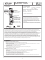
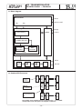
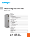
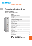
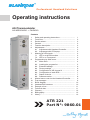
Professional Headend Solutions
Operating instructions
ASI Transmodulator
ASI MPEG RADIO ®
FM-RADIO
Contents
1.
2.
3.
4.
5.
6.
7.
8.
9.
10.
11.
12.
13.
14.
15.
16.
17.
Safety and operating instructions .................................
Front view ......................................................................
Device variant ................................................................
General ..........................................................................
Function description .....................................................
Adjustments ..................................................................
6.1 Adjustment with Headend Controller ..................
6.2 Adjustment with PC/Laptop ................................
Meaning of LED signals ................................................
7.1 LED`s at the ASI sockets ....................................
7.2 LED`s on Front panel ..........................................
Programming by Web server ........................................
8.1 Main menu ...........................................................
8.2 Loading the program list .....................................
8.3 Extended settings .................................................
8.4 Factory settings ...................................................
8.5 Configuration of ASI channel 2 ...........................
8.6 Configuration of static RDS .................................
8.7 Status of device ...................................................
8.8 Software version .................................................
Manual menu control at the Headend Controller ........
Trap messages .............................................................
Block diagram ..............................................................
Headend BUS structure ..............................................
Example of use .............................................................
Technical data ..............................................................
Glossary ........................................................................
Bibliography .................................................................
History ..........................................................................
1
2
2
2
2
2
2
2
3
3
3
4
4
5
6
6
6
7
7
8
9
9
10
10
11
11
12
12
12
ATR 221
Part N°: 9860.01
ATR
221
Part N°: 9860.01
ASI TRANSMODULATOR
ASI MPEG RADIO ®
FM-RADIO
1. Safety and operating instructions
When assembling, starting-up and adjusting the modules, it is necessary to consider the system specific
references in the manual instruction!
The modules may only be installed and started up by authorized technical personnel!
When assembling the modules into the receiving points, the adherence of the EMC regulations is to be
secured!
The assembly and wiring have to be done without voltage!
All active modules may only be operated with the Headend Controller HCB 100 or Bus Extender
BEB 100!
The main voltage and the operating voltage of the modules working by DC have to be in complience to
the operating parameters described in the technical datas.
With all work the defaults of the DIN EN 50083 have to be considered! Especially the safety
relevant execution of the DIN EN 50083/1 [3] is necessary!
-1-
ASI TRANSMODULATOR
ATR
221
Part N°: 9860.01
ASI MPEG RADIO ®
FM-RADIO
2. Front view
3. Device variant
ATR 221
9860.01
BLINE
6 x FM-Radio
2 x ASI (TS) ®
[87,5...108 MHz]
managed by
SNMP
ASI TRANSMODULATOR
ASI MPEG RADIO ®
FM RADIO
DCS
ASI/TS-MODE burst, continuous / 188,204
ASI/TS-RATE
270/0.65...210 Mbps
INPUT LEVEL
200...880 mVpp
FM OUT
87.5...108 MHz
OUTPUT LEVEL
max. 6 x 110 dBµV
SUPPLY CURRENT
0.75 A
Minimum software requirements for HCB 100:
9650.03:
Version 2.34*
9650.04/.05: Version 3.18*
ASI-TS Input 1
LED Input 1
ASI-TS Input 2/Output
LED Input 2/Output
ASI
IN
TYPE: ATR 221 Part No.:9860.01
ASI
IN/OUT
*) Updates: www.blankom.de
ASI TRANSMODULATOR
ASI MPEG RADIO ®
FM RADIO
Type: ATR 221 Part No.:9860.01
ASI/TS-MODE burst, continuous / 188,204
ASI/TS-RATE
270/0.65...210 Mbps
INPUT LEVEL
200...880 mVpp
FM OUT
87.5...108 MHz
OUTPUT LEVEL
max. 6 x 110 dBµV
SUPPLY CURRENT
0.75 A
X2
X1
STANDBY
READY 1
READY 2
ADDR.
Operating voltage/
control bus
LED “STANDBY” (red)
LED “READY1” (green)
LED “READY2” (green)
LED “ADDR.” (yellow)
Adress selction switch
4. General
The ATR 221 ASI transmodulator is one component of
the B-LINE headend system which has been designed as a
complete package for medium-sized distribution networks.
The component makes it possible to produce up to 6 radio
programmes coded as MPEG2 from two ASI transport streams in
the FM range.
All the components are programmed via a single central control
unit and thereafter each component will function independently.
FM
Output coupler “Input”
IN
OUTPUT
LOOP
Output coupler “Output”
OUT
gile
gile
managed by
DCS
SNMP
5. Function description
The transport streams (TS) passed on by the input section are processed on entering the system. The SI data are
extracted and sent on to the control system so that the services to be decoded can be displayed and selected. At the
same time, the audio streams to be decoded are filtered out of the transport streams, as are the RDS data,
and these are passed to the DSP. The DSP decodes the MPEG data streams which it receives. The RDS data
received from the TS processing stage and are sent on, together with the decoded MPEG data streams, to the FPGA of
the modulator. 6 complete FM modulators for VHF are implemented in the FPGA. The audio signals are subjected to
19-kHz filtering in these. Next comes the stereo processing: the audio signals are added or subtracted and are
modulated to match the 38-kHz carrier; to the audio signal a 19-kHz pilot tone and the RDS data are added. The MPX
signal produced in this way is then modulated by FM. The FM signals are combined and passed through a D/A
converter. They are then available either via a directional coupler or, simply, direct at the component output port. Each
FM channel produced can be configured individually and independently of the others.
6. Adjustments
6.1 Adjustment with the Headend Controller
· Adjustment of the addresses at the Bus Extender BEB 100 and at the modules
· Activation of the programming mode of each module by selecting the line (BEB 100) and the module position (01... 15) at the
Headend Controller(HCB 100)
®
yellow LED will be lit up til the beginning of the parameter adjustment
· Adjustment of the ATR 221 parameter (see chapter 9)
®
green LED is lit up
· After the programming the ATR 221 will be automatically switched into the operating status
®
yellow LED lights up briefly / green LED is lit up
6.2 Adjustment with the PC / Laptop
· Condition for the remote programming is an “online - connection” after IP - standard and an ethernet connection at
the PC / Laptop
· Adjustment of the line / position addresses at the Bus Extender BEB 100 as well as at the modules
· At the Headend Controller HCB 100 IP - address input (e.g. 192.168.001.001)
· For “direct connection” between a PC and HCB 100 use a crossed patch cable (RJ 45)
· For connection over a deviation use an uncrossed patch cable
· HTML - browser start-up and put in IP - address as target address
· If connected correctly the HTML - control surface at the PC will open up and a blue LED (LINK) at the HCB 100 will be lit up
· All adjustment of the modules are specified at the control surface
The manual instructions of the Headend Controller HCB 100 and the Bus Extender BEB 100 have to be considered!
-2-
ATR
221
Part N°: 9860.01
ASI TRANSMODULATOR
ASI MPEG RADIO ®
FM-RADIO
7. Meaning of LED signals
7.1 LED`s at the ASI sockets
Colour
Green
Yellow
Status
permanently
illuminated
flashing
permanently
illuminated
flashing
Meaning of display
ASI channel has been configured as input
no ASI signal
ASI channel has been configured as output
no ASI signal
7.1 LED`s on front panel
Colour (Name)
Red (STANDBY)
Green (READY 1)
Green (READY 2)
Yellow (ADDR)
Status
permanently
illuminated
flashing
permanently
illuminated
flashing
permanently
illuminated
flashing
off
illuminated/flashing
Meaning of display
Modul is on standby
Modul faulty (Hardware)
Modul working, everything ok
Error warnings depending on signal:
ASI without sync (e.g. when there is no input signal)
at least one of the adjusted Audio-PID`s can not be decoded
Modul working, everything ok
Error warnings depending on signal:
ASI without sync (e.g. when there is no input signal)
at least one of the adjusted Audio-PID`s can not be decoded
ASI channel 2 has been configured as output
Remote control access/Data exchange
-3-
ATR
221
Part N°: 9860.01
ASI TRANSMODULATOR
ASI MPEG RADIO ®
FM-RADIO
8. Programming by Web server *
8.1 Main menu
Name
Name of module, editable (max. 30 characters)
ASI channel
Status
ASI channel 2
shows the ASI channel (1 or 2) currently in use
If there is a channel input (there will always be channel 1, and after configuration channel 2),
this shows whether there is SYNChronisation or noSYNChronisation at input port.
If channel 2 has been configured as output, the message will be “Channel has been
configured as output”.
configuration button for the ASI of channel 2 (see Menu 5)
FM channel
Channel name
display the settings for the FM output channel(s) (1 to 6)
Name of programme in the relevant FM channel, editable (max. 25 characteres)
Programme settings
Programme list
ASI channel
Audio-PID
This loads the list of available programmes. The pre-selection is between
“all programmes” or “only radio programmes” (see Menu 2).
the options are: 1 / 2
Audio PID for the programme, can be freely chosen between 0 and 16383
FM output
RF signal
Output frequency
RF level corretion
Output attenuation
RF output mode
the options are: on or off
Adjustment range: 87500...108000 kHz
Adjustment range: +3 …-3 dB 0.5-dB steps (per channel)
Adjustment range: 0 … 31 dB 1-dB steps (modul)
Selection: loop / output only
* Further Information can be found in HCB manual
-4-
ATR
221
Part N°: 9860.01
ASI TRANSMODULATOR
ASI MPEG RADIO ®
FM-RADIO
Audio settings
Audio-Mode
Audio-Amplification
Selection: Mono / Mono1 / Mono2 / Stereo / Auto
Adjustment range: +6 ... -10 dB in 0.5 dB steps
RDS settings
Data source / Mode
RDS-PID
Selection: RDS-PID / Audio-PID / Static / Off
freely choosen between 0 … 16383
Redirection to the setting menu: Configuration of the static RDS (see Menu 6)
Operating status
SNMP-Trap messages
Selection: On, Off, Reset
Selection: On, Off
Redirection to the relevant setting menus
Extendet settings
see Menu 3
Factory settings
see Menu 4
Status
see Menu 7
Software versions
see Menu 8
8.2 Load programm list (Menu 2)
This menu contains a list of all services contained in the ASI stream or in both ASI streams. Depending on what has
been pre-slected, either all services or radio services only will appear. A service can be selected for each of the 6 FM
channels.
-5-
ATR
221
Part N°: 9860.01
ASI TRANSMODULATOR
ASI MPEG RADIO ®
FM-RADIO
8.3 Extended settings (Menu 3)
FM channel
Pre emphasis
shows the settings for the FM output channel(s) (1 to 6)
Selection: 50 µs / 75 µs / Off
Modulation settings
Pilot signal
Pilot Hub correction
RDS signal
RDS Hub correction
Selection: On / Off
Adjustment range: +2 ... -2 kHz in 0,1-kHz steps
Selection: On / Off
Adjustment range: +2 ... -2 kHz in 0,1-kHz steps
8.4 Factory settings (Menu 4)
When this menu is called up, all the settings made on the EEPROM will be deleted and replaced by the default
settings. The modul will go back to these default values. Once the setting process is over, there will be automatic
return to the main menu.
8.5 Configuration of ASI channel 2 (Menu 5)
In this menu, the ASI for channel 2 can be separately configured as an input ASI or as an output that acts as a loop for
the input
-6-
ATR
221
Part N°: 9860.01
ASI TRANSMODULATOR
ASI MPEG RADIO ®
FM-RADIO
8.6 Configuration of static RDS (Menu 6)
Configuration of static RDS
FM channel
shows the settings for the FM output channel(s) (1 to 6)
Output frequency
shows the frequencies set for the FM channel (in kHz)
PI code
can be set between 0000 and FFFF (hexadecimally)*
PS name
8 characters of the name of the programme or service being transmitted
Radio text
max. 64 characters, which can be transmitted statically
PTY code
Programme type selected
EON service
Selection: On or Off
M/S code
Selection: music / language
DI code
Decoder identification control code, entered decimally. Default setting: 1 (stereo)
TP signal
Selection: On or Off
TA signal
Selection: On or Off
CT signal
Selection: On or Off
RDS time
shows the time transmitted in the RDS
* The current list of PI codes for German radio broadcasters can be found on the following website:
www.irt.de./de/themengebiete/digitaler-hoerfunk/radio-daten-system-rds.html
8.7 Device status (Menu 7)
-7-
ATR
221
Part N°: 9860.01
ASI TRANSMODULATOR
ASI MPEG RADIO ®
FM-RADIO
ASI channel
Status
Data rate
Actual data proportion
TS-ID
shows the ASI channel (1 or 2) currently in use
synchronisation status
data rate of ASI channel
…of which actual data constitute …%
shows theTS-ID
FM channel
Output frequency
Audio status
shows the details for the FM output channel(s) (1 to 6)
shown in kHz
audio status information
Dynamic RDS data
PI-Code
PS-Name
Radio text
shows the sender's PI code as contained in the data stream
shows the service name as contained in the data stream
shows the radio text as contained in the data stream
Information
Error memory
Temperature
Device number
Device index
shows the errors arising in internal communication between the controllers
temperature of terminals board
shows the device number
shows the device index
8.8 Softwareversion (Menü 8)
Name of device, item number, address in headend
Software versions
Shows the software versions for the controllers as follows:
- Controller of terminals board
- Transport stream manager
- Boot controller for the VHF modulator FPGA
- VHF modulator FPGA
- RDS encoder
- MPEG decoder
- Boot controller for FPGA of input ASI
- FPGA for input ASI
-8-
ATR
221
Part N°: 9860.01
ASI TRANSMODULATOR
ASI MPEG RADIO ®
FM-RADIO
9. Manual menu control at the Headend Controller (HCB 100)
Start - ATR 221
Edit or End
Power Status
On/ Reset / Off
Name
ASI channel configuration
ASI channel 2
Input / Output
RF Output
RF operating mode
Attenuation
only output / loop through
0...31 dB
Channel 1...6 or End
Programme settings
Channel name
ASI-TS source
Audio PID
1/2
0...16383
FM Output
RF output
Output frequency
RF level correction
On/Off
87500...108000 kHz
+3...-3 dB
Audio settings
Audio mode
Audio gain
mono/mono1/mono2/stereo/auto
+6...-10 dB
RDS adjustments
RDS Mode/ source
RDS PID
RDS PI Code
RDS PS Name
RDS PTY Code
RDS TP Signal
RDS TA Signal
RDS M/S Signal
RDS DI Code
RDS EON
RDS CT Signal
RDS-PID/Audio-PID/static/Off
0...16383
0x0000...0xFFFF
(8 characters)
(selection)
On/Off
On/Off
music/speech
On/Off
On/Off
Adjustments Pre emphasis/Modulation
50 µs / 75 µs / Off
On/Off
+2...-2 kHz
On/Off
+2...-2 kHz
Pre emphasis
Pilot Signal
Pilot Hub correction
RDS Signal
RDS Hub correction
End - ATR 221
10. Trap messages
Serial no.
01
02
03
04
05
06
07
08
09
Message
Signal OK
Input not sync
MPEG: Open Error
System reset
MPEG-Decoder not sync
Power fail
MPEG-Decoder sync
ATMEGA: Open Error
NIOS: Open Error
Type
INFORMATION
WARNING
CRITICAL
WARNING
WARNING
CRITICAL
INFORMATION
CRITICAL
CRITICAL
-9-
Notes
Modul works correct
Input not synchronized
Access error MPEG-Decoder
Reset after intern error
MPEG-Decoder not synchronized
Error on supply voltage
MPEG-Decoder synchronized
Access error FM-Boot controller
Access error RDS-Encoder
ASI TRANSMODULATOR
ATR
221
Part N°: 9860.01
ASI MPEG RADIO ®
FM-RADIO
11. Block diagram
ASI-Frontend
ASI IN
TS1
ASI IN or OUT
TS2
Processing
Supply
Control
SI-Processing
Control
DSP
6 x MPEG Decoder
6 x FM
Modulator
RDS
Controller
FPGA
RF
RF IN
D
RF OUT
A
Modul
ADDR. 01
Modul
ADDR. 15
Modul
ADDR. 01
Modul
ADDR. 15
Modul
ADDR. 15
BEB 100
ADDR. 01
Modul
ADDR. 01
Modul
signal processing
unit
BEB 100
ADDR. 02
BEB 100
Bus Extender
BEB 100
ADDR. 15
HCB 100
Headend
Controller
HCB 100
12. Headend BUS structure
The number of the possible module connections (00 ... 15) to a BEB
100 depends on the total power consumption of this line!
- 10 -
ATR
221
Part N°: 9860.01
ASI TRANSMODULATOR
ASI MPEG RADIO ®
FM-RADIO
13. Example of use
14. Technical data
ASI Input
Level range
Data rate
Connector type
Impedance
ASI - Polarity
ASI Output
Level
Data rate
Connector type
Impedance
ASI - Polarity
ASI - Signal processing
Data rate
ASI - Transmission format
Input
Output
TS - Transmission format
Input
Output
Signal processing
FM-Modulator / FM Output
Max. FM-deviation
NF-level range (deviation correction)
Frequency range
Frequency step
Output impedance
Output return loss
Amplitude response 40 Hz...15 kHz,
reference: 400 Hz, preemphase 50 µs
Rejection of modulation frequencies
between 18.9…19.1 kHz
and 23…100 kHz
Total harmonic distortion
40 Hz…15 kHz at 40 kHz deviation
40 Hz…15 kHz at 75 kHz deviation
Difference tone attenuation D2 between
40 Hz…15 kHz
SNR weighted
(Pre- und Deemphase 50 µs, R, L)
SNR unweighted
(Pre- and Deemphase 50 µs, R, L)
Crosstalk attenuation between
40 Hz…100 Hz
100 Hz…15 kHz
200 … 880 mVpp
270 Mbps
BNC socket
75 W
regular / inverted
800 mVpp ± 10%
270 Mbps
BNC socket
75 W
normal
0.625 … 78 Mbps
continuous, burst
burst
188, 204 Byte
188, 204 Byte
EN 50083-9 [1]
75 kHz
-10…+6 dB
87.5…108 MHz
50 kHz
75 W
> 16 dB
< ± 0.5 dB
> 40 dB
Output frequency inaccuracy after
24 hours at 25 °C
Temperature depended frequency
inaccuracy
Spurios between
47…87.5 MHz and 111…862 MHz
87.5…111 MHz
Frequency error
Output level (switchable)
direct output (without directional coupler)
with directional coupler
Total level
Individual level
Connector
Stereo – Coder
Processing
Deviation pilot
RDS – Coder
Processing
Deviation
Supported services
Operating parameters
Current / voltage
Residual ripple of
supply voltage
Enviromental conditions
Temperature range
Temperature range
(for data keeping)
Relative humidity
Method of mounting
Location of mounting
> 66 dB bei 400 Hz
> 60 dB bei 400 Hz
Physical information
Dimensions (l x w x h)
without 19” - adapter
> 70 dB
with 19” - adapter
Weight
> 66 dB (Quasi-PeakDetector, CCIR weighted) Delivery content
1 x BUS -connector
> 72 dB (Quasi-PeakDetector, CCIR unweighted) 1 x F connecting cable 140 mm
> 38 dB (- 26 dBFS)
> 40 dB (- 26 dBFS)
- 11 -
< ± 2 kHz
< ± 2 kHz
³
64 dB
³
60 dB
< 3 kHz
max. 6 x 110 dBµV
max. 6 x 100 dBµV
1 dB (0…31 dB)
0.5 dB (± 3 dB)
F socket
Multiplex, CCIR
6.7 kHz
EN 62106:2001 [2]
2.4 kHz
PS, PTY, TP, TA, EON, PI,
RT, MS, CT, DI
12 V (± 0.2 V) / 750 mA
£
10 mVpp
-10 ... +55 °C
5 ... 45 °C
£
80 % (non condensing)
vertical
splash-proof and
drip-proof
50 x 276 x 148 mm
50 x 301 x 148 mm
1,200 g
ASI TRANSMODULATOR
ATR
221
Part N°: 9860.01
ASI MPEG RADIO ®
FM-RADIO
15. Glossary
AM
AP
ASI
ATV
AV
CCIR
C/N
CT
D/A
DI
DSP
DVB
EON
ETSI
FIFO
FM
FPGA
HE
HF
http
ID
IIC
IP
LED
MC
MIB
MPEG
NIM
PCR
PI
PID
PLL
PMT
PS
PTY
RDS
RF
RT
SNMP
SPI
TA
TP
TS
Amplitude modulation
Anschlussplatte (Terminals board)
Asynchronus Serial Interface
Analog Television
Audio/Video
Comité Consultatif International Radiocommunication
Carrier to Noise ratio
Clock Time
Digital/Analog
Decoder-Identifications-Control code
Digitaler Signal processor
Digital Video Broadcasting (-C Cable, -S Satellit, -S2 Satellite 2)
Enhanced other Network
European Telecommunications Standards Institute
First In – First Out
Frequency modulation
Field Programmable Gate Array
Headend
High frequency
hypertext transfer protocol
Identifier
Inter-Integrated Circuit
Internet Protocol
Light Emitting Diode
MicroController
Management Information Base
Moving Picture Experts Group
Network Interface Module
Program Clock Reference
Program Identification
Program Identifier
Phase Locked Loop
Program Map Table
Program Service Name
Program Type
Radio Data System
Radio Frequency
Radio Text
Single Network Management Protocol
Serial Peripheral Interface
Traffic Announcement
Traffic program
Transport stream
16. Bibliography
[1] EN 50083-9: Cabled distribution systems for television, sound and interactive multimedia signals, part 9:
Interfaces for CATV/SMATV headends and similar professional equipment for DVB/MPEG-2 transport streams
[2] EN 62106:2001 : Specification of the radio data system (RDS) for VHF/FM sound broadcasting in the
frequency range from 87.5 to 108.0 MHz (IEC 62106:2000); German version
[3] EN 50083-1: Cabled distribution systems for television, sound and interactive multimedia signals, safety
requirements
17. History
Version
Date
1.00
28.10.2008 Basic document
Modification
Editor
Häußer, Poch
Options and other TV standards available upon request! Changes due to technical progress possible!
BLANKOM Antennentechnik GmbH
Hermann - Petersilge - Str. 1 ·
07422 Bad Blankenburg ·
Germany ·
Telefon +49 (0) 36741/ 60-0 ·
Fax+49 (0) 036741/ 60-101
- 12 -