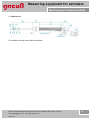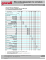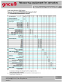
1
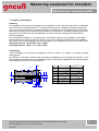
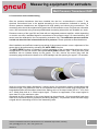
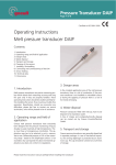
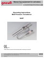
Measuring equipment for extruders
Melt Pressure Transducer DAIP
Operating Instructions
Melt Pressure Transducer
DAIP
Zertifiziert nach
ISO 9001
Please read this instruction manual carefully before installing the transducer
Gneuss Kunststofftechnik GmbH, Moenichhusen 42, 32549 Bad Oeynhausen, Germany,
mail: [email protected], web: www.gneuss.com
Version 2.1
1
Measuring equipment for extruders
Melt Pressure Transducer DAIP
Contents:
1. Introduction
2. Operating range and field of application
3. Danger areas
4. Waste disposal
5. Transport and storage
6. Cleaning of the sensors
7 Installing / Uninstalling
8. Connecting and commissioning of the DAI
9. Sensor heating
10. Technical data
11. Dimensions
Gneuss Kunststofftechnik GmbH, Moenichhusen 42, 32549 Bad Oeynhausen, Germany,
mail: [email protected], web: www.gneuss.com
Version 2.1
2
Measuring equipment for extruders
Melt Pressure Transducer DAIP
1. Introduction
Melt pressure transducers are precise measuring probes which obtain their measuring accuracy
and long life span only if they are properly handled. These operating instructions should be studied
carefully before installing the sensor, thus ensuring a trouble-free operation. Nevertheless, should
you encounter any difficulties, please feel free to contact our service technicians, who will be
pleased to be of assistance.
2. Operating range and field of application:
Gneuss melt pressure transducers have exclusively been designed for the pressure monitoring of
liquid, doughy or pasty materials at high temperatures. These must have a homogeneous
constitution. The application area has to be selected in such a manner, that a max. Differential
pressure of 2% of the measuring range – based on the diaphragm surface- is not exceeded. Any
use beyond the above mentioned application area does not conform to regulations
3. Danger areas:
In the complete application area of the melt pressure transducer, there is a risk of combustion. If
the pressure transducer is not installed or uninstalled correctly during the applying of pressure
there is a risk of hot media emerging.
4. Waste disposal:
Pressure transducers filled with mercury, have to be disposed of as hazardous waste.
A free of charge and ecologically-friendly disposal can be carried out by Gneuss Kunststofftechnik
GmbH
5. Transport and storage:
Gneuss pressure transducers are generally dispatched in separate packages. In case of
mechanical exposure, the sensing diaphragm is protected by an aluminium cap. This cap should
be screwed on at all times of storage.
6. Cleaning of the sensors
In order to clean the diaphragm, the sealing surface and the process thread the sensor must have
the same temperature as the plastic melting point. The diaphragm and the sealing surface can be
wiped down with a soft cloth, the thread can be cleaned with a steel brush.
(Do not come into contact with the diaphragm surface)
Gneuss Kunststofftechnik GmbH, Moenichhusen 42, 32549 Bad Oeynhausen, Germany,
mail: [email protected], web: www.gneuss.com
Version 2.1
3
Measuring equipment for extruders
Melt Pressure Transducer DAIP
7. Installing / Uninstalling
Installing
On installation of the pressure transducer it is imperative to note, that the sensor bore corresponds
to the dimensions mentioned below. The fitting accuracy can be checked by means of a test bolt
Prior to mounting the sensor, the thread should be covered with a heat resistant paste. Should the
machinery with the sensor drilling still be at production temperature, a certain preheating period for
the sensor should be taken into consideration, in order to avoid a seizing of the sensor due to
thermal expansion.
On mounting the transducer, it is important to note that the sensor is not screwed in at an angle
and that the sensor does not fall into the bore. It is of vital importance that the force for installing
the sensor must only be applied at the shaft (hexagon). Do not apply any force to the sensor head!
Starting torque for 1/2-20 UNF = max. 30 Nm
Starting torque for M 18 x 1,5 = max. 50 Nm
Uninstalling
The uninstalling of the pressure transducer has to be done in a heated up condition (plastic
melting point)
On removal of the sensor, please take note that the diaphragm is not brought into contact. It is of
vital importance that the force for installing the sensor must only be applied at the shaft (hexagon).
Do not apply any force to the sensor head!
45°±1°
( d2 )
( d4 )
( d3 ) ( d1 )
0,05 A
A
(c)
d1
d2
d3
d4
a
b
c
M18x1,5
½“20UNF 2A
+0,05
Ø 10,1
Ø 7,9 +0,05
Ø 16,1 +0,1
Ø 10,7 +0,1
Ø 20 +0,2
Ø 13 +0,2
6,1 –0,1
5,7 –0,1
4 –0,2
3,2 –0,2
25
19
(b)
(a)
Gneuss Kunststofftechnik GmbH, Moenichhusen 42, 32549 Bad Oeynhausen, Germany,
mail: [email protected], web: www.gneuss.com
Version 2.1
4
Measuring equipment for extruders
Melt Pressure Transducer DAIP
8. Connections and commissioning
After the pressure transducer has been installed into the line, as described in section 7, the
electrical connections have to be applied according to the connections indicated in section 8.
Gneuss pressure transducers are equipped with high quality and robust plug connections. The
connecting wire should be soldered with great care as transmission errors of signals can otherwise
occur. We recommend using Gneuss prefabricated connecting wires which are available ex- stock.
Pressure sensors of the type DAI are fitted with an integrated pressure amplifier, which depending
on version can offer a standard signal in accordance to the pressure range. On commissioning, the
sensor must be calibrated to the corresponding evaluation unit. The calibration process must be
carried out when the line is heated and at zero pressure. Please proceed as described below.
After installation and sufficient warming-up period of the pressure sensor a zero- adjustment of the
sensor has to be performed by activating the AUTO ZERO function.
The AUTO ZERO function is initiated by a short connection of the corresponding wires (see wiring
configuration). For the DAI version with optical AUTO ZERO initiation (DAI-…-6PA) the zero point
calibration can be initiated directly at the sensor. For this, remove the screw plug near the
connecting plug and direct the beam of an LED flashlight into this opening for approx. 3-5 seconds.
Insert the screw plug again afterwards; it simply serves for protection against contamination and
extraneous light. The protection class is not impaired even without the screw plug being fitted.The
integrated amplifier will thereafter transmit the starting value of its output scale (0V at 0…10V, 0mA
at 0…20mA and 4mA at 4…20mA output signal. Function is suppressed, if the output signal is
more than 5% of the maximum value.
Afterwards an 80% inspection of the output signal can be performed. All corresponding lead wires
need to be connected for this procedure (see wiring diagram). The pressure sensor will now supply
a signal which is according to 80% of the measuring value.
Gneuss Kunststofftechnik GmbH, Moenichhusen 42, 32549 Bad Oeynhausen, Germany,
mail: [email protected], web: www.gneuss.com
Version 2.1
5
Measuring equipment for extruders
Melt Pressure Transducer DAIP
Electrical wiring configuration 2-Wire sensor
Connector type: PT02A-10-6P.
4...20mA
FAB
E C
D
Pin
Function
Colour coding
(Gneuß – cable)
A
Supply / Signal +
yellow
B
Supply / Signal -
white
C
free
brown
D
Auto Zero
green
E
80%
pink
F
Auto Zero / 80%
grey
Pin D and Pin F are utilised fort he activation of the Auto-Zero function. The Zero-point is hereby
merely shifted. The signal amplification is not affected, as it is shifted linear to the zero point.
In order to generate the 80% signal, pins E and F must be connected
Electrical wiring configuration 3-Wire Sensor
Connector type PT02A-10-6P.
0...10V
0/4...20mA
FAB
E C
D
Pin
Function
Colour coding
(Gneuß – cable)
A
Signal +
yellow
B
Supply /Signal/Auto Zero -
white
C
Supply +
brown
D
free
green
E
Auto Zero
pink
F
80%
grey
In order fort he Auto-Zero function to be activated, pins E and B have to be connected with each
other. Only the Zero-point is shifted. The signal amplification remains untouched, as it shifts linear
to the zero-point. In order to generate the 80% signal, pins F and B must be connected.
Gneuss Kunststofftechnik GmbH, Moenichhusen 42, 32549 Bad Oeynhausen, Germany,
mail: [email protected], web: www.gneuss.com
Version 2.1
6
Measuring equipment for extruders
Melt Pressure Transducer DAIP
Electrical wiring configuration 4-Wire Sensor
Connector type PT02A-10-6P.
0...10V
0/4...20mA
FAB
E C
D
Pin
Function
Colour coding
(Gneuß – cable)
A
Signal +
yellow
B
Signal/Auto Zero -
C
Supply +
D
Supply / Auto Zero -
E
Auto Zero
pink
F
80%
grey
*
white
brown
*
green
* Pins B and D are connected internally
In order to activate the Auto-Zero function, pins A, C and D must be connected. Only the Zero point
is shifted. The signal amplification remains in place, as it shifts linear to the zero point. In order to
generate the 80% signal, pins F, C and D must be connected.
Electrical wiring configuration 4-Wire Sensor Version 98
Connector type PT02A-98-P.
0...10V
0/4...20mA
A
E
D
Pin
F B
C
Function
Coulour coding
(Gneuß – cable)
A
Auto Zero
pink
B
Signal +
yellow
C
Signal/Auto Zero -
D
Speisung/Auto Zero - *
green
E
Speisung +
brown
F
80%
grey
*
white
* Pins C and D are connected internally
In order to activate the Auto-Zero function, pins A, C and D have to be connected. This leads to a
shifting of the zero point. The signal amplification remains in place, as it shifts linear to the zero
point.
Gneuss Kunststofftechnik GmbH, Moenichhusen 42, 32549 Bad Oeynhausen, Germany,
mail: [email protected], web: www.gneuss.com
Version 2.1
7
Measuring equipment for extruders
Melt Pressure Transducer DAIP
The 80% signal is generated by connecting pins F,C and D
Thermo couple connection:
PCA.0S.302.CLL
1
+
2
-
Thermocouple
Heater connection:
PCA.3S.302.CLL
24 VAC / 150 W
Sensor heating
9. Sensor Heating
The pressure transducer DAIpremium is a high-efficient sensor with integrated thermocouple and
integrated heating element. During the production process, the thermocouple can be used as
control measurement at any time. The integrated heating serves to protect the sensor from
damage to the membrane when processing problematic plastic melts, e.g. polycarbonate, since
these contract very much when cooling down. In the production process, it is sufficient to set the
nominal value of the temperature control approx. 30-50°C below the melt temperature. By
switching on the heating, the front part of the sensor incl. membrane can be adjusted to such a
temperature that the melt in the membrane area remains viscous. Further, the heating can be used
to help to remove the sensor out of a “cold” machine. For this, it is normally sufficient to heat up the
sensor for approx. 15 to 30 minutes (depending on the temperature).
Attention:
The sensor heating must always be controlled by the integrated thermocouple. The sensor should
only be heated up when being installed, otherwise the heating element might be damaged. During
the heating process, the temperature level in the whole sensor and drilling area can be very high.
After having installed the pressure transducer in the line as described under point 7, the electrical
connection has to be carried out according to the connections indicated section 8.
Gneuss Kunststofftechnik GmbH, Moenichhusen 42, 32549 Bad Oeynhausen, Germany,
mail: [email protected], web: www.gneuss.com
Version 2.1
8
Measuring equipment for extruders
Melt Pressure Transducer DAIP
10.Technical Data:
Pressure range:
See order specification
Supply :
19…32 VDC
Outputsignal:
0…10 V; 0…20 mA; 4…20 mA (see order specification)
Temperature element:
Heater :
Type J; K; L, PT 100 (see order specification)
24 V 150 W
Calibration point:
Accuracy:
specification)
Maximum over load:
Zero deviation with
Temperature Variations
at the membrane::
80 % of measuring range
0,50 % FSO respectively
150 % of measuring range
0,003 % from final value/°C
Zero deviation with
Temperature Variations
at the measuring head:
Maximum temperature at
the membrane:
Maximum. Temperature at
The measuring head:
EMC:
according to
0,25 % FSO (see order
0,003 % from final value/°C
300°C with NTX-filling (W)
400°C with Hg-filling (M)
500°C with NaK-filling (N)
85 °C
Electromagnetic distrubances and electromagnetic susceptibility
EN 61326
Degree of protection:
IP 55
Gneuss Kunststofftechnik GmbH, Moenichhusen 42, 32549 Bad Oeynhausen, Germany,
mail: [email protected], web: www.gneuss.com
Version 2.1
9
Measuring equipment for extruders
Melt Pressure Transducer DAIP
11. Dimensions
For available variations see order specification
Gneuss Kunststofftechnik GmbH, Moenichhusen 42, 32549 Bad Oeynhausen, Germany,
mail: [email protected], web: www.gneuss.com
Version 2.1
10
Measuring equipment for extruders
Melt Pressure Transducer DAIP
Gneuss Kunststofftechnik GmbH, Moenichhusen 42, 32549 Bad Oeynhausen, Germany,
mail: [email protected], web: www.gneuss.com
Version 2.1
11
Measuring equipment for extruders
Melt Pressure Transducer DAIP
Gneuss Kunststofftechnik GmbH, Moenichhusen 42, 32549 Bad Oeynhausen, Germany,
mail: [email protected], web: www.gneuss.com
Version 2.1
12
Measuring equipment for extruders
Melt Pressure Transducer DAIP
Gneuss Kunststofftechnik GmbH, Moenichhusen 42, 32549 Bad Oeynhausen, Germany,
mail: [email protected], web: www.gneuss.com
Version 2.1
13
Measuring equipment for extruders
Melt Pressure Transducer DAIP
Gneuss Kunststofftechnik GmbH
Moenichhusen 42
32549 Bad Oeynhausen, Germany
Phone: +49 (0) 5731 5307-0
Fax: +49 (0) 5731 5307-77
Mail: [email protected]
www.gneuss.de
Gneuss Kunststofftechnik GmbH, Moenichhusen 42, 32549 Bad Oeynhausen, Germany,
mail: [email protected], web: www.gneuss.com
Version 2.1
14