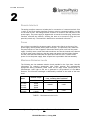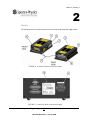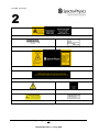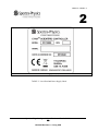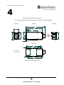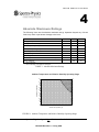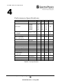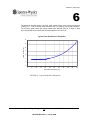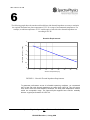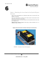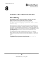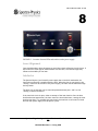
1
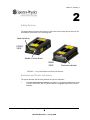
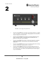
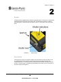
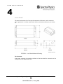
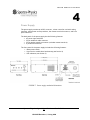
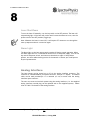
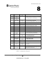
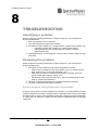
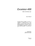
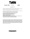
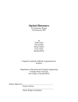
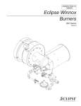
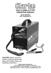
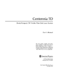
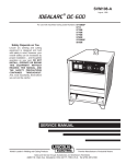
Cyan Scientific Laser User’s Guide SPECTRA-PHYSICS A Division of Newport Corporation Cyan Scientific Laser User’s Guide Thank you for purchasing a Spectra-Physics product. Your Spectra-Physics Cyan laser is a quality product that has been designed and manufactured to provide reliable performance. The laser system has been designed for use in lab-based experimentation and measurement. This manual is an important part of your purchase as it will help familiarize you with the laser and explain the numerous features that have been designed into it. Please read this manual thoroughly before using your laser. Please contact Spectra-Physics or your authorized Spectra-Physics distributor should you have questions regarding specific applications or if you require additional information. Contact information: Website: www.newport.com/lasers Email: [email protected] Spectra-Physics reserves the right to change or update the contents of this manual and to change the specifications of its products at any time without prior notification. Every effort has been made to keep the information in this document current and accurate as of the date of publication or revision. However, no guarantee is given or implied that this document is error free or that it is accurate with regard to any specification. Spectra-Physics has prepared this manual for use by its customers as a guide for the proper installation, operation and/or maintenance of the Spectra-Physics Cyan laser. Spectra-Physics and the Spectra-Physics Logo are trademarks of Newport, Inc. 2006 Spectra-Physics. All rights reserved. 1355 Terra Bella Avenue Mountain View, California CA 94043 USA. Phone 800.456.2552 Website: WWW.NEWPORT.COM Spectra-Physics Cyan Laser User’s Guide Revision 4, 19 Aug 2008 Spectra-Physics Cyan Scientific Laser User’s Guide 2 UG13055 Revision 4 , 19 Aug 2008 Table of Contents 1 - INTRODUCTION 3 2 - LASER SAFETY 5 Safety Summary 5 Precautions for the Safe Operation of Class IIIb Lasers 5 Safety Devices 7 Emission and Power Indicators 7 Shutter 9 Key Switch 9 Remote Interlock 10 Fuses 10 Maximum Emission Levels 10 Labels 11 WASTE ELECTRICAL AND ELECTRONIC EQUIPMENT (WEEE) RECYCLING LABEL 14 SOURCES OF ADDITIONAL INFORMATION 15 Laser safety Standards 15 Equipment and Training 16 3 - LIMITED WARRANTY 17 4 - LASER SPECIFICATIONS 19 SYSTEM DESCRIPTION 19 Laser Head 20 Power Supply 21 ABSOLUTE MAXIMUM RATINGS 23 PERFORMANCE SPECIFICATIONS 24 5 - UNPACKING 25 6 - INSTALLATION 26 THERMAL CONSIDERATIONS 26 LASER HEAD MOUNTING 29 Option 1: Mounting the Laser Head to the Spectra-Physics Heat sink 30 Option 2: Mounting the Laser Head to Custom Heat sink 31 Safety Interlock 31 AC Power for Power Supply 31 Connecting the Umbilical Cable 31 7 - OPERATING INSTRUCTIONS LASER STARTUP 32 32 Laser Alignment 33 Interlocks 33 Spectra-Physics Cyan Scientific Laser User’s Guide 1 UG13055 Revision 4 , 19 Aug 2008 Laser Shut-Down 34 Alarm Light 34 ANALOG INTERFACE 34 TROUBLESHOOTING 36 IDENTIFYING A PROBLEM 36 ANALYZING THE PROBLEM 36 System Analysis Using Reference Components 36 SERVICE 37 PREVENTATIVE MAINTENANCE 37 Spectra-Physics Cyan Scientific Laser User’s Guide 2 UG13055 Revision 4 , 19 Aug 2008 I N T R O D U C T I O N 1 INTRODUCTION This manual contains information you need to safely install, operate, and maintain your Spectra-Physics Cyan laser system. Please be alert to the safety considerations and specific procedures regarding the Spectra-Physics Cyan laser head. Throughout the manual you will see graphic icons representing important information in the text. The purpose of these icons is to provide a visual convention to alert you of a stop in the flow of the manual, where an important note or safety hazard alert is posted. NOTE is an important procedure of which you should be aware before proceeding. CAUTION alerts you of a potential danger to equipment or to the user. WARNING indicates an imminent danger to the user. REMINDER is a helpful hint to procedures listed in the text. The conventions are listed as follows, showing the picture you will see. NOTE CAUTION WARNING REMINDER This manual was designed to be easy to read and understand. If you have any questions or suggestions, please let us know. Spectra-Physics Cyan Scientific Laser User’s Guide 3 UG13055 Revision 4 , 19 Aug 2008 I N T R O D U C T I O N 1 [THIS PAGE INTENTIONALLY LEFT BLANK] Spectra-Physics Cyan Scientific Laser User’s Guide 4 UG13055 Revision 4 , 19 Aug 2008 L A S E R S A F E T Y 2 LASER SAFETY Safety Summary Follow the instructions contained in this manual to ensure proper installation and safe operation of your laser. CAUTION: The Spectra-Physics Cyan lasers are Class IIIb lasers as defined by the Federal Register 21 CFR 1040.10 Laser Safety Standard. The standard requires that certain performance features and laser safety labels be provided on the product. Photographs of the warning labels in place on the laser are shown later in this section. WARNING: This product produces laser light at 488nm. Diffuse as well as specular beam reflections can cause severe eye or skin damage. Residual invisible light at 976nm wavelength might also be present. The American National Standards Institute publishes a laser safety standard for users entitled American National Standard for the Safe Use of Lasers (ANSI Z136.1). Spectra Physics strongly recommends that laser users obtain and follow the procedures described in this ANSI standard. Copies may be obtained from: American National Standards Institute Inc. 1430 Broadway New York, NY 10018 Or Laser Institute of America 2424 Research Parkway Orlando FL 32826 Precautions for the Safe Operation of Class IIIb Lasers • • Users should have an initial eye examination prior to operating the laser equipment followed by periodic re-examinations. Wear protective eyewear at all times; selection depends on the wavelength and intensity of the radiation, the conditions of use and the visual function required. Protective eyewear is available from suppliers listed in the Laser Focus World, Lasers and Optronics, and Photonics Spectra buyer’s guides. Consult the ANSI and ACGIH standards listed at the end of this section for guidance. Spectra-Physics Cyan Scientific Laser User’s Guide 5 UG13055 Revision 4 , 19 Aug 2008 L A S E R S A F E T Y 2 • • • • • • • • • Maintain a high ambient light level in the laser operation area so the eye’s pupil remains constricted, reducing the possibility of damage. Avoid looking at the output beam; even diffuse reflections are hazardous. Avoid blocking the output beam or its reflections with any part of the body. Establish a controlled access area for laser operation. Limit access to personnel trained in the principles of laser safety. Enclose beam paths wherever possible. Post prominent warning signs near the laser operating area. (See EN 60825-1, ANSI Z136.1 Section 4.7). Install the laser so that the beam is either above or below eye level, standing or seated. Set up shields to prevent any unnecessary specular reflections or beams from escaping the laser operation area. Set up a beam dump to capture the laser beam and prevent accidental exposure. Use of controls or adjustments, or performance of procedures other than those specified herein may result in hazardous radiation exposure There are no user serviceable components in this equipment. You should not attempt repairs on the product; instead, report all problems to Spectra-Physics Customer Service or your local distributor for assistance. Please contact Spectra-Physics, if you have any questions regarding the safe operation of this equipment Operating this laser without due regard for these precautions or in a manner that does not comply with recommended procedures may be dangerous. At all times during installation and operation of your laser, avoid unnecessary exposure to laser or collateral radiation∗ that exceeds the accessible emission limits listed in “Performance Standards for Laser Products,” United States Code of Federal Regulations, 21CFR1040.10(d) Do not look at any laser light directly or through any optical lens. When handling the product, do not look directly at the light generated by the product. The laser complies with the following safety standards: EN/IEC 60825-1 FDA/CDRH 21 CFR Parts 1040.10-11 ∗ Any electronic product radiation, except laser radiation, emitted by a laser product as a result of or necessary for the operation of a laser incorporated into that product. Spectra-Physics Cyan Scientific Laser User’s Guide 6 UG13055 Revision 4 , 19 Aug 2008 L A S E R S A F E T Y 2 Safety Devices The images below illustrate the location of the various laser safety devices that will be described in more detail in the following text. Laser Aperture FRONT VIEW Shutter Control Knob REAR VIEW Emission indicator FIGURE 1: Laser Head Shutter and Emission Indicator Emission and Power Indicators The system provides the following emission and power indicators: • The laser head emission indicator (see Figure 1) illuminates yellow when there is power to the laser, but no optical emission, and green when there is optical emission. Spectra-Physics Cyan Scientific Laser User’s Guide 7 UG13055 Revision 4 , 19 Aug 2008 L A S E R S A F E T Y 2 FIGURE 2: Power supply front panel devices • The power supply MAINS switch (see Figure 2) illuminates red when it is toggled to the “On” position. In this state power is being supplied to the electronics in the power supply and to the laser head. • The power supply CAUTION LED (see Figure 2) illuminates yellow when mains power to the unit is turned on, and the key switch is turned to the “ON” position, such that laser current is enabled. • The power supply READY LED (see Figure 2) illuminates green after completion of the warm-up sequence, when the laser is fully operational and emitting stable power. • The power supply REMOTE LED (see Figure 2) illuminates green when the analog interface is enabled (see “Analog Interface” in Section 7). • The power supply ALARM LED (see Figure 2) illuminates red when there is an internal fault. (The alarm may be cleared by toggling the power switch off and on). If the Alarm LED is not cleared, contact Spectra-Physics Technical Support, or your local distributor. Spectra-Physics Cyan Scientific Laser User’s Guide 8 UG13055 Revision 4 , 19 Aug 2008 L A S E R S A F E T Y 2 Shutter The laser head is equipped with a manually operated shutter. The shutter is operated by turning the knob on the front of the laser head. The direction of rotation to open or close the shutter is indicated near the shutter control, on the label on top of the laser head. FIGURE 3: Shutter detail Key Switch Turning the key switch on the power supply to the ON position allows the laser to turn on, provided the remote interlock loop is connected at the analog interface (see “Remote Interlock”). The key cannot be removed once the switch is turned to the ON position. The key switch is located below the MAINS power switch on the front panel of the power supply (see Figure 2). Spectra-Physics Cyan Scientific Laser User’s Guide 9 UG13055 Revision 4 , 19 Aug 2008 L A S E R S A F E T Y 2 Remote Interlock The analog interface connector includes pins for connection of a remote interlock. Pins 1 and 3 of the 25-pin analog interface connector must be connected together in order for the laser to start. The analog interface connector is located on the rear panel of the power supply. The power supply is shipped with an interlock override plug, which when installed, overrides the interlock, allowing the laser to be turned on using the front panel key switch only. The interlock is described in more detail in Section 7. Fuses One 1A fuse is provided for the power supply. Access to the fuse is on the rear of the power supply, directly below the AC power cord input. To replace the fuse, make sure the power switch is in the off position. Disconnect the AC power cord from the power supply. Carefully insert a small flat-head screwdriver into the slot located at the bottom of the AC power input. Gently pry the door open and remove the fuse holder. Replace the fuse, slide the fuse holder back into place and close the cover. Connect the AC power cord to the power supply. Note: A spare fuse is provided in the fuse assembly. Maximum Emission Levels The following are the maximum emission levels possible for the Cyan laser. Use this information for selecting appropriate laser safety eyewear and implementing appropriate safety procedures. These values do not imply actual system power or specifications. Laser light at 976 nm is generated in the production of the 488nm emission. This infra-red wavelength is substantially confined to the inside of the laser head. Model PC13054 PC13055 PC14011 PC14202 PC14962 PC14963 Nominal output 488nm 10mW 20mW 40mW 50mW 75mW 100mW Maximum possible output at any time, including fault conditions 488nm 986nm <100mW <1mW <180mW <1mW TABLE 1: Maximum emission levels Spectra-Physics Cyan Scientific Laser User’s Guide 10 UG13055 Revision 4 , 19 Aug 2008 L A S E R S A F E T Y 2 Labels The following section contains illustrations of the laser head and power supply labels. FIGURE 4: Location of Labels on the Laser Head FIGURE 5: Location of labels on the Power Supply Spectra-Physics Cyan Scientific Laser User’s Guide 11 UG13055 Revision 4 , 19 Aug 2008 L A S E R S A F E T Y 2 Laser Head Left Side Label (1) Head Serial Number Label (2) Model Number Label (3) Laser Head Top Label (4) Laser Head Right Side Label (5) Emission Indicator Caution Label (6) Warranty Seal (7) Laser Aperture Label (8) Firmware Revision Number Label (9) Spectra-Physics Cyan Scientific Laser User’s Guide 12 UG13055 Revision 4 , 19 Aug 2008 L A S E R S A F E T Y 2 Power supply label (10) TABLE 2: Laser Head and Power Supply Labels Spectra-Physics Cyan Scientific Laser User’s Guide 13 UG13055 Revision 4 , 19 Aug 2008 L A S E R S A F E T Y 2 Waste Electrical and Electronic Equipment (WEEE) Recycling Label To Our Customers in the European Union: As the volume of electronics goods placed into commerce continues to grow, the European Union is taking measures to regulate the production and disposal of waste from electrical and electronic equipment. Toward that end, the European Parliament has issued directives instructing European Union member states to adopt legislation concerning the reduction, recovery, re-use and recycling of waste electrical and electronic equipment. The directive addressing the reduction, recovery, re-use and recycling of waste electrical and electronic equipment is referred to as WEEE. In accordance with this directive, the accompanying product has been marked with the WEEE symbol. See Label 9 in Table 2. The main purpose of the symbol is to designate that at the end of its useful life, the accompanying product should not be disposed of as normal municipal waste, but should instead be transported to a collection facility that will ensure the proper recovery and recycling of the product's components. The symbol also signifies that this product was placed on the market after 13 August, 2005. At this time, regulations for the disposal of waste electrical and electronic equipment vary within the member states of the European Union. Please contact a Newport / Spectra-Physics representative for information concerning the proper disposal of this product. Spectra-Physics Cyan Scientific Laser User’s Guide 14 UG13055 Revision 4 , 19 Aug 2008 L A S E R S A F E T Y 2 Sources of Additional Information Laser safety Standards Safe Use of Lasers (Z136.1) American National Standards Institute (ANSI) 11 West 42nd Street New York, NY 10036 Tel: (212) 642-4900 Occupational Safety and Health Administration (Publication 8.1-7) U.S. Department of Labor 200 Constitution Avenue N. W., Room N3647 Washington DC 20210 Tel: (202) 693-1999 A Guide for Control of Laser Hazards, 4th Edition, Publication #0165 American Conference of Governmental and Industrial Hygienists (ACGIH) 1330 Kemper Meadow Drive Cincinnati, OH 45240 Tel: (513) 742-2020 Internet: www.acgih.org.htm Laser Institute of America 13501 Ingenuity Drive, Suite 128 Orlando FL 32826 Tel: (800) 445-4200 Compliance Engineering Canon Communications LLC 11444 W. Olympic Boulevard Los Angeles CA 90064 Tel: (310) 445-4200 International Electrotechnical Commission Journal of the European Communities EN 60825-1 Safety of Laser Products – Part 1: Equipment classification, requirements and user’s guide Tel: +41 22-919-0211 Fax: +41 22-919-0300 Internet: www.iec.ch Spectra-Physics Cyan Scientific Laser User’s Guide 15 UG13055 Revision 4 , 19 Aug 2008 L A S E R S A F E T Y 2 Cenelec 35 Rue de Stassartstraat B-1050 Brussels, Belgium Tel: +32 2 519 68 71 Internet: www.cenelec.org Document Center Inc. 111 Industrial Road, Suite 9 Belmont CA 94002 Tel: (650) 591-7600 Internet www.document-center.com Equipment and Training Laser Safety Guide Laser Institute of America 13501 Ingenuity Drive, Suite 128 Orlando FL 32826 Tel: (800) 34LASER Internet: www.laserinstitute.org Laser Focus World Buyers Guide Laser Focus World Pennwell Publishing 98 Spit Rock Road Nashua NH 03062 Tel: (603) 891-0123 Internet: www.laserfocusworld.com Photonics Spectra Buyer’s Guide Photonics Spectra Laurin Publications Berkshire Common PO Box 4949 Pittsfield MA 01202-4949 Tel: (413) 499-0514 Internet: www.photonics.com Spectra-Physics Cyan Scientific Laser User’s Guide 16 UG13055 Revision 4 , 19 Aug 2008 L I M I T E D W A R R A N T Y 3 LIMITED WARRANTY Spectra-Physics warrants its Products to be free from defects in material and workmanship and to perform in the manner and under the conditions specified in the Product specifications for twelve (12) months from shipment. This warranty is the only warranty made by Spectra-Physics with respect to its Products and no person is authorized to bind Spectra-Physics for any obligations or liabilities beyond this warranty in connection with its Products. This warranty is made to the original Purchaser only, is nontransferable and may only be modified or amended by a written instrument signed by a duly authorized officer of Spectra-Physics. Sub-systems manufactured by other firms, but integrated into Spectra-Physics Products, are covered by the original manufacturer’s warranty and Spectra-Physics makes no warranty, express or implied, regarding such sub-systems. Products or parts thereof which are replaced or repaired under this warranty are warranted only for the remaining, unexpired portion of the original warranty period applicable to the specific Product replaced or repaired. NOTE: DISCLAIMER THE FOREGOING WARRANTY IS EXCLUSIVE AND IN LIEU OF ALL OTHER WARRANTIES WHETHER WRITTEN, ORAL OR IMPLIED, AND SHALL BE THE PURCHASER’S SOLE REMEDY AND SPECTRA-PHYSICS’ SOLE LIABILITY IN CONTRACT OR OTHERWISE FOR THE PRODUCT. SPECTRA-PHYSICS EXPRESSLY DISCLAIMS ANY WARRANTY OF MERCHANTABILITY OR FITNESS FOR A PARTICULAR PURPOSE. The Purchaser’s exclusive remedy with respect to any defective Product shall be to have Spectra-Physics repair or replace such defective Product or credit the Purchaser’s account, whichever Spectra-Physics may elect in its sole discretion. If it is found that any Product has been returned which is not defective, the Purchaser will be notified and such Product returned at the Purchaser’s expense. In addition, a charge for testing and examination may, at Spectra-Physics’ sole discretion, be made on any Product so returned. These remedies are available only if: i) Spectra-Physics is notified in writing by the Purchaser promptly upon discovery of a Product defect, and in any event within the warranty period; ii) Spectra-Physics’ examination of such Product discloses to SpectraPhysics’ satisfaction that such defects actually exist and the Product has not been repaired, worked on, altered by persons not authorized by Spectra-Physics, subject to misuse, negligence or accident, or connected, installed, used or adjusted otherwise than in accordance with the instructions furnished by Spectra-Physics. Spectra-Physics Cyan Scientific Laser User’s Guide 17 UG13055 Revision 4 , 19 Aug 2008 L I M I T E D W A R R A N T Y 3 The following warranty conditions shall apply to all Spectra-Physics products unless amended by a written instrument signed by a duly authorized officer of Spectra-Physics: ADJUSTMENT – No electrical, mechanical or optical adjustments to the product(s) are permitted. PARTS AND LABOR - New or factory-built replacements for defective parts will be supplied for twelve (12) months from date of shipment of the product. Replacement parts are warranted for the remaining portion of the original warranty period. There will be no charge for repair of products under warranty where the repair work is done by Spectra-Physics. Shipping and transportation charges shall be the sole responsibility of the customer. NOT COVERED BY THE WARRANTY – Damage to any optical surface from improper handling or cleaning procedures. This applies specifically to those items subjected to excess laser radiation, contaminated environments, extreme temperature or abrasive cleaning. Damage due to ESD, abuse, misuse, improper installation or application, alteration, accident, negligence in use, improper storage, transportation or handling. No warranty shall apply where the original equipment identifications have been removed, defaced, altered or where there is any evidence of alterations, adjustments, removal of protective outer enclosure, any attempt to repair the product by unauthorized personnel or with parts other than those provided by Spectra-Physics. DAMAGE IN SHIPMENT - Your laser product should be inspected and tested as soon as it is received. The product is packaged for safe delivery. If the product is damaged in any way, you should immediately file a claim with the carrier or, if insured separately, with the insurance company. Spectra-Physics. will not be responsible for damage sustained in shipment. All Spectra-Physics products are F.O.B. shipped Spectra-Physics factory or Spectra-Physics distributor. CLAIMS ASSISTANCE - Call Spectra-Physics Customer Service or your local distributor for assistance. Give our representative the full details of the problem. Helpful information or shipping instructions will be provided. If requested, estimates of the charges for nonwarranty or other service work will be supplied before work begins. RETURN PROCEDURE - Customers must obtain a Return Merchandise Authorization Number from Spectra-Physics prior to returning units. Products being returned for repair must be shipped in their original shipping cartons or equivalent to avoid damage. Spectra-Physics Cyan Scientific Laser User’s Guide 18 UG13055 Revision 4 , 19 Aug 2008 L A S E R S P E C I F I C A T I O N S 4 LASER SPECIFICATIONS The following specifications are for Spectra-Physics Cyan Scientific lasers operating at a fixed optical output power. System Description The Cyan Scientific laser is a compact solid-state frequency-doubled laser that provides stable 488nm laser output at fixed power levels between 10mW and 100mW depending on the model. The system consists of: Laser head – incorporates all optical components, some signal-conditioning and control electronics, and a manual safety shutter. Power supply – incorporates all electronics for control of the laser head (and optional heat sink fan). Umbilical cable – connects the power supply to the laser head. The standard umbilical cable is a 1.8m long 25-conductor 24 AWG shielded cable wired straight through, with a standard 25-pin DB-25 connector on each end. The end connecting to the laser head is female and the end connecting to the power supply is male. Stated laser performance is only guaranteed with cables supplied by SpectraPhysics. An optional heat sink with an integral cooling fan is available. Spectra-Physics Cyan Scientific Laser User’s Guide 19 UG13055 Revision 4 , 19 Aug 2008 L A S E R S P E C I F I C A T I O N S 4 Laser Head The laser head contains all of the optical components of the laser, and is where the light is generated. It includes a mechanical shutter and emission indicator (see Section 2) FIGURE 6: Laser Head Mechanical Drawing. Fan Connector A fan power connector is located at the back of the laser head for connection to the cooling fan on the optional heat sink. Spectra-Physics Cyan Scientific Laser User’s Guide 20 UG13055 Revision 4 , 19 Aug 2008 L A S E R S P E C I F I C A T I O N S 4 Power Supply The power supply contains an AC-DC converter, a laser controller card with analog interface, mains power and key switches, the remote interlock connector, and front panel indicators. The back panel of the power supply has the following features: • AC power input with fuse • 25-pin umbilical cable connector • 25-pin analog interface connector (includes remote interlock) • 9-pin RS-232 connector The front panel of the power supply includes the following features: • Mains power switch • Key switch to enable laser head startup (see Section 2) • LED indicators (see Section 2) FIGURE 7: Power supply mechanical dimensions Spectra-Physics Cyan Scientific Laser User’s Guide 21 UG13055 Revision 4 , 19 Aug 2008 L A S E R S P E C I F I C A T I O N S 4 Optional Heat Sink Mechanical Diagram The following diagram shows the dimensions of the heat sink and fan assembly. FRONT VIEW SIDE VIEW BACK VIEW 207 180 50 12.8 102.5 80 AIRFLOW 71.6 70 35 5.4 BOTTOM VIEW 150 8.5 4.5 127 ALL DIMENSIONS ARE IN MILLIMETERS 72 20.2 70.4 7 127 150 FIGURE 8: Optional Heat sink Spectra-Physics Cyan Scientific Laser User’s Guide 22 UG13055 Revision 4 , 19 Aug 2008 69 L A S E R S P E C I F I C A T I O N S 4 Absolute Maximum Ratings The following limits are the absolute maximum ratings. Operation beyond any of these limits may result in permanent damage to the laser. Parameter Min Max Units Storage Temperature –30 +70 °C Storage Relative Humidity * 0 100 % Ambient Operating Temperature 4 40 °C Base plate Operating Temperature 4 55 °C 90 % Non-Operating Altitude 0 70,000 feet Operating Altitude 0 10,000 feet 3 G 100 G Operating Relative Humidity ** Vibration (50 to 500 Hz sinusoidal 0.25 octaves/min) Shock Tolerance * Non-condensing. ** Non-condensing—see graph on next page. TABLE 3: Absolute Maximum Ratings Relative Humidity [%] Ambient-Temperature and Relative-Humidity Operating Range 90 90 80 80 70 70 60 60 50 50 40 40 30 30 20 20 10 10 0 0 4 6 8 10 12 14 16 18 20 22 24 26 28 30 32 34 36 38 40 o Ambient Temperature [ C] FIGURE 9: Ambient Temperature and Relative Humidity Operating Range Spectra-Physics Cyan Scientific Laser User’s Guide 23 UG13055 Revision 4 , 19 Aug 2008 L A S E R S P E C I F I C A T I O N S 4 Performance Specifications Parameter Conditions Wavelength PC13054 PC13055 PC14011 PC14202 PC14962 PC14961 Output Power Output Power Stability Short term Long term Maximum IR Output Power Noise 20 Hz – 2 MHz, RMS 20 Hz – 20 kHz, pk–pk Polarization Extinction Ratio 2 hours, +/- 3°C Perpendicular to base plate Power in Band Min Nom Max Units 487.5 488.0 488.5 nm 10 20 40 50 75 100 13 22 44 53 78 104 15 27 49 55 80 105 -1 -5 100:1 +1 +5 0.1 % % mW 0.20 1 % % 250:1 98 % Mx2 1.1 My2 1.1 Beam Asymmetry At beam waist Beam Diameter @ 1/e2 1:1.1 0.65 0.75 mm 1.1 mrad –30 +30 µrad –0.25 –2.5 +0.25 +2.5 mm mrad –200 +200 mm 7 min 30 W Beam Divergence Pointing Stability 3 hours, +/- 3°C Static Alignment Tolerances Beam Position Beam Angle Beam Waist Position Warm-up time With respect to laser exit port To stable power mW Total power dissipation TABLE 4: Laser Specifications Spectra-Physics Cyan Scientific Laser User’s Guide 24 UG13055 Revision 4 , 19 Aug 2008 U N P A C K I N G 5 UNPACKING All Spectra-Physics products are inspected and tested prior to shipment from the factory. In the event that there is damage to the shipping container (holes or crushing, etc.) insist that a representative of your shipping carrier is present while you unpack the contents. Damage caused by shipping is the responsibility of the shipping carrier and all claims must be routed through their claims department. NOTE: a) Like all electronic devices, this device contains static sensitive components. It should be handled only with proper Electrostatic Discharge (ESD) grounding procedures. Observe all ESD precautions and procedures while handling the product. Ensure you and any surfaces on which the product lies are correctly grounded. b) Carefully unpack the contents from the boxes. c) The complete Cyan Scientific system in shipped in two separate boxes. Check contents of each box against the packing list to ensure all parts have been received. d) Inspect each item to assure it is not damaged. Ensure use of full ESD precautions as parts are ESD sensitive. e) It is recommended that you keep the shipping package until the unit has been installed and verified as being fully operational. Spectra-Physics Cyan Scientific Laser User’s Guide 25 UG13055 Revision 4 , 19 Aug 2008 I N S T A L L A T I O N 6 INSTALLATION This chapter describes the setup and installation of the laser head and power supply. Please read and understand this chapter thoroughly before proceeding with the laser installation. The Spectra-Physics Cyan laser module consists of a laser head and power supply joined by an umbilical cable. An optional Spectra-Physics heat sink assembly with a cooling fan is also available (see Chapter 4 “Laser Specifications” for a detailed mechanical description of each item). Thermal Considerations CAUTION: It is important that the laser head be attached to an adequate heat sink with thermal grease/heat sink compound when operating (see footnote* on next page). Failure to attach the laser head to an adequate heat sink will result in overheating of the laser head causing a laser shutdown. Thermal Specifications Min Max Description Ambient Operating Temperature Base plate Operating Temperature 4°C 40°C 4°C 55°C Operating environmental limits. Operation outside this range will result in thermal shutdown. NOTE: The Spectra-Physics heat sink is designed to provide adequate cooling for reliable laser operation. For optimum operation of the heat sink, the heat sink fan should be connected to the laser head via the cable provided. Also, adequate clearance must be provided at the back of the unit near the fan to ensure proper airflow. Spectra-Physics Cyan Scientific Laser User’s Guide 26 UG13055 Revision 4 , 19 Aug 2008 I N S T A L L A T I O N 6 The maximum thermal load of the laser head module under worst-case environmental conditions is < 14 W for steady-state operation and < 19 W during the startup procedure. The following graph shows the typical steady-state thermal load for a range of base plate temperatures and a heat sink thermal impedance of 0.55ºC/W. Typical Laser Head Power Dissipation 14 12 Thermal Load [W] 10 8 6 4 2 0 0 5 10 15 20 25 30 35 40 o Baseplate Temperature [ C] FIGURE 10: Typical Head Power Dissipation Spectra-Physics Cyan Scientific Laser User’s Guide 27 UG13055 Revision 4 , 19 Aug 2008 45 50 55 I N S T A L L A T I O N 6 The following graph shows the maximum allowable heat sink thermal impedance necessary to maintain the required maximum base plate temperature of 55ºC for a range of environmental temperatures. For example, an ambient temperature of 35ºC would require a heat sink with a thermal impedance not exceeding 0.95ºC/W. He atsink Re quire me nts 2.5 Thermal Impedance [ o C/W] 3 2 1.5 1 0.5 0 0 5 10 15 20 25 30 35 40 Am bient Tem perature [oC] FIGURE 11: Heat sink Thermal Impedance Requirements To guarantee performance across all allowable operating conditions, we recommend using a heat sink with thermal impedance no greater than 0.65ºC/W. This will ensure that, under worst-case environmental conditions, the base plate temperature remains within the acceptable range. The Spectra-Physics-supplied heat sink/fan assembly delivers a typical performance of 0.55ºC/W. Spectra-Physics Cyan Scientific Laser User’s Guide 28 UG13055 Revision 4 , 19 Aug 2008 I N S T A L L A T I O N 6 NOTE: If the Spectra-Physics heat sink is not used, we recommend that the customerprovided heat sink be milled to a flatness of 0.05 mm or better over the entire mounting surface of the laser head and that thermal grease or heat sink compound* is used to maximize thermal contact. * The following thermal greases/heat sink compounds (or equivalent) are recommended: • Wakefield Engineering Non-silicone Thermal Compound 126-4 • Thermagon T-Putty 504 • Thermagon T-Mate 2905C Laser Head Mounting The following describes the procedure for mounting the Spectra-Physics Cyan laser head to the heat sink. You will need: - 4 x screws (supplied as part of the installation kit) o type: M3 x 0.5 x 12 mm - 4 x dished toothed M3 washers (supplied as part of the installation kit) - thermal grease (not supplied) - calibrated torque screwdriver (not supplied). NOTE: The laser head must be electrically grounded in order to meet the ESD immunity requirements of EN61000-6-2. REMINDER: It is important that the laser head be attached with thermal grease to an adequate heat sink when operating. Failure to attach the laser head with thermal grease to an adequate heat sink will result in overheating of the laser head causing a laser shutdown. CAUTION: Ensure that both surfaces at the laser head-heat sink interface are clean and a light coating of thermal grease is applied. Any voids may cause heat dissipation problems with the laser head. Uneven application of thermal grease may result in deviation from intended bore sighting. Spectra-Physics Cyan Scientific Laser User’s Guide 29 UG13055 Revision 4 , 19 Aug 2008 I N S T A L L A T I O N 6 Option 1: Mounting the Laser Head to the Spectra-Physics Heat sink - Align the laser head against the 3 reference locator pins on the heat sink. See diagram on next page. - Insert the toothed washers on the M3 screws. Ensure that the concave surface of the washer faces away from the screw head. - Loosely tighten the four screws with washers into the attachment holes on the heat sink in diagonal order. - Tighten the four screws in diagonal order using a torque screwdriver set to a maximum torque of 100 N cm. Align the laser head into the 3 reference locator pins on the heat sink FIGURE 12: Illustration of Laser Head Alignment. Spectra-Physics Cyan Scientific Laser User’s Guide 30 UG13055 Revision 4 , 19 Aug 2008 I N S T A L L A T I O N 6 Option 2: Mounting the Laser Head to Custom Heat sink It is recommended that the customer-supplied heat sink include reference locator pins to ensure proper alignment of the laser head (see Figure 12). The mounting procedure follows as described in Option 1 above. Safety Interlock An analog interface interlock is provided on the rear panel of the power supply. The interlock allows the user to disable the laser externally for safety purposes. An example would be configuring the laser such that the interlock opens/closes when a door is opened/closed. To use the interlock feature, remove the interlock override plug (if it is installed) and then connect the switch (or relay) contacts across the interlock connector inputs. Internally a sense circuit has a 10 kohm pull-up resistor to +5V. If this external interlock circuit is open, or the input voltage exceeds 2.5 V, the laser will be disabled. See Section 7 for more information regarding the analog interface and its operation. AC Power for Power Supply Plug the power cable provided into the power input receptacle on the power supply back panel, and the other end into a standard wall socket. Connecting the Umbilical Cable CAUTION: Before connecting or disconnecting the electrical cables to the laser head, ensure that the power switch is turned off. Also, plug the power supply into the wall socket to bring the system to ground before connecting the umbilical cables. The umbilical cable must be screwed into place prior to operating the laser. Do not apply power until all cables and connections have been attached. Components of this laser system are not hot switchable. Damage may be caused by current surges if power is applied while attaching or removing cables. Spectra-Physics Cyan Scientific Laser User’s Guide 31 UG13055 Revision 4 , 19 Aug 2008 T R O U B L E S H O O T I N G 8 OPERATING INSTRUCTIONS Laser Startup Prior to turning the laser on, ensure that personnel in the vicinity have proper protective eyewear and that the beam path will be well contained. Move the power switch to the ON position. The switch will appear red. The LED’s on the Laser Power supply (Figure 13) will be all off. The LED on the laser head will be orange. When laser emission is required, open the manual shutter on the laser head, and turn the key switch to the ON position. The amber CAUTION LED on the laser power supply will turn on. After approximately 10 seconds, the LED on the laser head will turn green, and light will emerge from the laser head. The laser is now in startup mode. The amber CAUTION LED on the power supply will remain lit at all times when the laser is generating blue light. The Spectra-Physics Cyan laser will remain in startup mode for up to 7 minutes. During startup, the laser power supply performs an auto-calibration. As a result, the output power will fluctuate from very low levels to up to 20% above the rated output power. The “Ready” LED on the laser power supply will emit green when the laser has completed its startup sequence and is in operational mode. Spectra-Physics Cyan Scientific Laser User’s Guide 32 UG13055 Revision 4 , 19 Aug 2008 T R O U B L E S H O O T I N G 8 FIGURE 13: Location of status LEDs and switches on the power supply. Laser Alignment Care should be taken during alignment to avoid direct back reflections into the laser. If more than 5% of laser light is reflected back into the laser, the reflected light may influence the stability of the laser. Interlocks The Spectra-Physics Cyan Scientific power supply has an interlock mechanism. An interlock override plug is supplied with the laser. When the plug is connected to the “Analog” connector on the rear of the power supply, the laser can be enabled through the key switch. The laser will not operate until a closed loop exists between pins 1 and 3 on the “Analog” interface connector. If the interlock circuit is open, either at startup of the laser head or after the laser head has become operational, the laser enters the interlocked state, causing the laser head to shut down. To re-enable the laser head, the interlock circuit must be closed and the laser power supply must be power cycled. Spectra-Physics Cyan Scientific Laser User’s Guide 33 UG13055 Revision 4 , 19 Aug 2008 T R O U B L E S H O O T I N G 8 Laser Shut-Down To turn the laser off manually, turn the key switch to the OFF position. The laser will stop emitting light. If the laser will not be used for several minutes or hours, turn the power switch to the OFF position (Toggle up). Note: Whenever the laser is turned off, it will require 5-7 minutes to run through the start up sequence when it is turned on again. Alarm Light The Alarm light on the laser power supply remains off during normal operation. When the Alarm light turns on, it indicates an internal error in the power supply. Turn off the key switch and power switch, and then turn them back on again. If the problem persists, see the trouble-shooting section of the manual or contact your local SpectraPhysics representative. Analog Interface The laser output can be turned on or off via the analog interface connector. The connector is a standard DB-25 pin female connector, with pin 17 “keyed”. A standard cable can be used provided pin 17 is removed (or cut) to match with the analog interface input connector. The user can create an interlock system using the analog interface. (i.e. the supplied analog interface override plug can be replaced with a user supplied system). Please refer to Table 5 for details of the analog interface. Spectra-Physics Cyan Scientific Laser User’s Guide 34 UG13055 Revision 4 , 19 Aug 2008 T R O U B L E S H O O T I N G 8 I/O – Signal level Pin # Signal Name Description 1 (+) Analog Interlock Loop 3 (-) Analog Interlock Loop 2 Laser On/Off 4, 5, 6 NC No connection 7 NC No connection 8 Power Monitor < 15 VDC, 12.5 mA typ. Connect pins 1 and 3 together to close interlock loop for normal operation. Input 0: < 0.4 V 1: > 3.5 V Output monitor V 0 = Turn laser and TEC controller OFF 1 = Turn laser and TEC controller ON If pin left open, the default value is 1 (laser, TEC ON) Analog output signal, 10 mA max. Used to remotely monitor the laser output power. 0.1V/mW 9 LD I Monitor 10, 11 GND 12 NC 13 V out 14 GND 15 Base plate Temperature Monitor Output monitor V 0 to 4.096 V signal output corresponding to a 0 to 100 degrees laser head base plate temperature 16 Laser locked Output 0: < 0.4 V 1: > 4.5 V 0 = Laser locked. Laser temperature and power are at their corresponding setting points 1 = Laser off/standby/not ready 17 NC 18 Analog Interface Enable 19 NC 20, 21, 22 GND 23 Alarm – Laser Failure 24 GND 25 Chassis GND Output monitor V Gain chip current monitor, 10 mA max, 1 V/A Main PCB signal ground No connection Output +12 V + 12 V, 100 mA max power supply Main PCB signal ground No connection Input 0: < 0.4 V 1: > 3.5 V 0 = Analog Interface enable 1 = Analog Interface disable No connection Main PCB signal ground Output 0: < 0.4 V 1: > 4.5 V 0 = Normal operation 1 = Laser fault Main PCB ground Chassis ground attached to power supply connector chassis ground, connector shells. TABLE 5: Analog Interface Description Spectra-Physics Cyan Scientific Laser User’s Guide 35 UG13055 Revision 4 , 19 Aug 2008 T R O U B L E S H O O T I N G 8 TROUBLESHOOTING Identifying a problem Please provide the following information to Spectra-Physics or your local SpectraPhysics representative: 1. Date the problem was first observed. 2. Laser head and power supply serial numbers. 3. Description of the problem (e.g. no output power, output power unstable, etc) • If possible, quantify the problem (e.g. output power drifting approximately 20% over 10 minute period or beam circularity approximately 70%) 4. Detailed description of the symptoms. Include status of power supply and laser head LEDs. Analyzing the problem Please provide the following information to Spectra-Physics or your local SpectraPhysics representative: 1. Description of the conditions under which the problem occurred: • Under which circumstances does the problem occur (e.g. during start-up, after several hours of continuous operation, etc.)? • What were the external conditions (temperature, humidity, electrical power voltage and frequency, setup, etc.)? • Did the laser work correctly before? If so, were any changes made to the setup or operational parameters? 2. Summary of operating parameters (if changed from factory settings). 3. Any other information that might be relevant. System Analysis Using Reference Components If another Cyan system or system component is available, it is recommended to further localize the problem. Do this by changing system components (laser head, power supply and cables) one at a time. If the symptoms vanish after changing a certain component, it is likely (but not absolutely certain) that the problem is associated with the changed component. Spectra-Physics Cyan Scientific Laser User’s Guide 36 UG13055 Revision 4 , 19 Aug 2008 T R O U B L E S H O O T I N G 8 Service There are no user serviceable components in this laser system. If you are still experiencing problems, or need further assistance please contact Spectra-Physics Technical Support at (800) 456-2552, or at [email protected], or your local distributor. Preventative Maintenance There is no maintenance required for the operation of this laser Spectra-Physics Cyan Scientific Laser User’s Guide 37 UG13055 Revision 4 , 19 Aug 2008 Contact information: Website: www.Newport.com Email: [email protected] Spectra-Physics reserves the right to change or update the contents of this manual and to change the specifications of its products at any time without prior notification. Every effort has been made to keep the information in this document current and accurate as of the date of publication or revision. However, no guarantee is given or implied that this document is error free or that it is accurate with regard to any specification. Spectra-Physics has prepared this manual for use by its customers as a guide for the proper installation, operation and/or maintenance of the Spectra-Physics Cyan laser. Spectra-Physics and the Spectra-Physics Logo are trademarks of Spectra-Physics. 2006 Spectra-Physics. All rights reserved. 1355 Terra Bella Avenue Mountain View, California CA 94053 USA. Phone 800.456.2552 Website: WWW.NEWPORT.COM Spectra-Physics Cyan Laser User’s Guide Revision 4, 19 Aug 2008 Spectra-Physics Cyan Scientific Laser User’s Guide 38 UG13055 Revision 4 , 19 Aug 2008