1
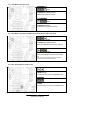
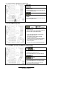
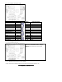
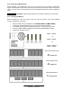
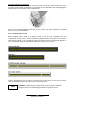
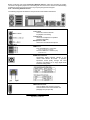
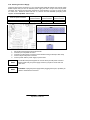
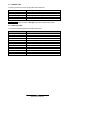
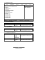
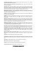
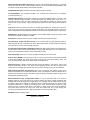
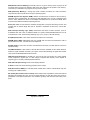
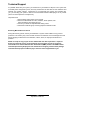
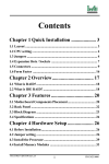
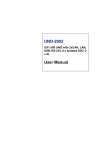
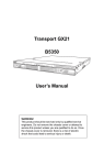
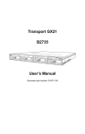
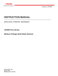
///
Thunder i7505
S2665
Revision 1.03
Copyright © TYAN Computer Corporation, 2002. All rights reserved. No part of this manual may be
reproduced or translated without prior written consent from TYAN Computer Corp.
All registered and unregistered rtademarks and company names contained in this manual are
property of their respective owners including, but not limited to the following.
TYAN, Thunder i7505 S2665 are trademarks of TYAN Computer Corporation.
Intel, Xeon, and combinations thereof are trademarks of Intel Corporation.
Microsoft and Windows are trademarks of Microsoft Corporation.
Phoenix BIOS is a trademark of Phoenix Technologies.
Winbond is a trademark of Winbond Electronics Corporation.
Adaptec is a trademark of Adaptec Inc.
AnalogDevice and ADM are trademarks of Analog Devices Inc.
Sony/Philips Digital Interface (SPDIF) is a trademark of Sony Corporation and Philips Electronics.
PS/2 is a trademark of International Business Machines Corporation.
Portable Document Format (PDF) is a trademark of Adobe Corporation.
Information contained in this document is furnished by TYAN Computer Corporation and has been
reviewed for accuracy and reliability prior to printing. TYAN assumes no liability and disclaims any
express or implied warranty rela ting to sale and/or use of TYAN products; we also assume no
including liability or warranties relating to fitness for a particular purpose or merchantability. TYAN
retains the right to make changes to product descriptions and/or specifications at any time without
notice. In no event will TYAN be held liable for any direct or indirect, incidental or consequential
damage, loss of use, loss of data or other malady resulting from errors or inaccuracies of
information contained in this document.
1
http://www.TYAN.com
Table of Contents
Before you begin…
………………………………….Page 3
Chapter 1: Introduction
1.1 Congratulations
1.2 Hardware Specifications
………………………………….Page 4
………………………………….Page 4
………………………………….Page 4
Chapter 2: Board Installation
2.0 Board Image
2.1 Board Parts, Jumpers and Connectors
2.2 Jumper and Connector Settings
2.3 AUX Audio and CD Audio Connector
2.4 Enable/Disable On board LAN Jumper
2.5 Fan Connectors
2.6 ACPI Wake-up Jumper for PS/2
2.7 ACPI Wake-up Jumper for USB Port- A ~ D
2.8 Slot- A PCI-X/PCI-2.2 Jumper
2.9 Slot-B and Slot-C PCI-X/PCI-2.2 Jumper
2.10 Clear CMOS Jumper
2.11 ACPI Wake-up Jumper for USB Port-E ~ F
2.12 IEEE 1394 Connectors
2.13 LCD Connectors Chassis Intrusion Connector
2.14 Front Panel Audio Connector
2.15 Chassis Intrusion Connector
2.16 Front Panel USB Header
2.17 Front Panel Conne ctor
2.18 SCSI RAID PCI Slot-C
2.19 OEM Reserved Connectors and Jumpers
2.20 Mounting the Motherboard
2.21 Installing the Memory
2.22 Installing the Processor and Heatsink
2.23 Installing Add -In Cards
2.24 Connecting External Devices
2.25 Installing the Power Supply
2.26 Attaching IDE and Floppy Drive Cables
2.27 Finishing Up
………………………………….Page 6
………………………………….Page 7
………………………………….Page 8
………………………………….Page 9
………………………………..Page 10
………………………………..Page 10
………………………………..Page 10
………………………………..Page 11
………………………………..Page 11
………………………………..Page 11
………………………………..Page 12
………………………………..Page 12
………………………………..Page 12
………………………………..Page 13
………………………………..Page 13
………………………………..Page 13
………………………………..Page 14
………………………………..Page 14
………………………………..Page 15
………………………………..Page 15
………………………………..Page 15
………………………………..Page 16
………………………………..Page 16
………………………………..Page 18
………………………………..Page 20
………………………………..Page 21
………………………………..Page 22
………………………………..Page 23
………………………………..Page 24
Chapter 3:BIOS
3.0 BIOS Setup Utility
3.1 BIOS Menu Bar
3.2 BIOS Legend Bar
3.3 BIOS Main Menu
3.4 BIOS Advanced Menu
3.5 BIOS Security Menu
3.6 BIOS Power Menu
3.7 BIOS Boot Menu
3.8 BIOS Exit Menu
………………………………..Page 25
………………………………..Page 25
………………………………..Page 26
………………………………..Page 26
………………………………..Page 27
………………………………..Page 28
………………………………..Page 31
………………………………..Page 31
………………………………..Page 32
………………………………..Page 33
Chapter 4: Diagnostics
4.1 Beep Codes
4.2 Flash Utility
………………………………..Page 34
………………………………..Page 34
………………………………..Page 34
Appendix I: Glossary
Technical Support
………………………………..Page 35
………………………………..Page 39
2
http://www.TYAN.com
Before you begin…
Check the box contents!
The retail motherboard package should contain the following:
1x Thunder i7505 S2665
1x 34-Pin floppy drive cable
1x Ultra160/320 LVD SCSI cable (if optional SCSI included)
1x Ultra-D M A-100/66/33 IDE cable
1x Thunder i7505 S2665 User’s Manual
1x TYAN driver CD
1x Adaptec Ultra160/Ultra320 SCSI driver diskette (if optional SCSI included)
1x I/O shield
2X CPU retention
If any of these items are missing, please contact your vendor/dealer for replacement before
continuing with the installation process.
3
http://www.TYAN.com
Chapter 1: Introduction
1.1 – Congratulations!
You are now the owner of one of the most advanced dual Intel Xeon processor solutions
available: the Thunder i7505 S2665. Based on Intel's E7505 chipset, the Thunder i7505 S266 5 is
Hyper-Threading ready - utilizing onboard resources so that many data threads can be handled
with ease by two processors.
With a 8x/4x AGP slot, six USB 2.0 and 1.1 compatible ports, two FireWire (IEEE-1394) ports,
four DDR DIMM sockets, a Gigabit Et hernet port , plus an optional Dual Channel Ultra320 SCSI,
the Thunder i7505 S2665 is fast and flexible enough to fit your server needs.
Remember to visit TYAN’s Website at http://www.tyan.com . There you can find information on all
of TYAN’s products with FAQs, distributors list and BIOS setting explanations.
1.2 – Hardware Specifications
Processor
Integrated SCSI (Manufacturing Option)
§ Dual mPGA604 ZIF sockets
§ Supports one or two Intel Xeon processors
with 512KB of integrated L2 cache
§ Onboard 4-phase VRM (VRM 9.1 spec)
§ Supports 400/533MHz Front-Side Bus
§ Adaptec 7902 dual channel Ultra160/320
SCSI at PCI- X 100MHz
§ Intel RAIDIOS and Adaptec Zero-Channel
RAID ready through a PCI slot
Integrated LAN
Chipset
§
§
§
§
§
§ Intel 82540EM Gigabit Ethernet
- (Manufacture loading option with Intel
82551QM 10/100Mbit Ethernet)
Intel E7505 chipset
MCH + ICH4 + P64H2 + FWH
Intel P64H2 supports two PCI-(X) buses
Winbond W83627HF Super I/O chip
Analog Device ADM1027 systems monitor
and multiple fan controller
Integrated Audio
§
§
§
§
§
§
§
Memory
§ Four 184- pin 2.5 -Volt DDR DIMM sockets
§ Dual channel memory bus
§ Supports ECC/non-ECC type unbuffered
memory modules
§ Supports PC1600/PC2100 DDR
(DDR200/DDR266)
§ Maximum 4 GB
Intel ICH4 AC’97 compliant audio link
AD1981A CODEC
Line-in, Line-out, Mic -in rear jacks
SPDIF digital output with rear RCA connector
Front panel audio header
One 4-pin CD-ROM audio input header
One 4-pin Auxiliary header
BIOS
§
§
§
§
§
§
§
Expansion Slots
§ Three independent PCI-(X) buses
§ One 8x/4x mode AGP Pro50 slot
§ One 6 4-bit 133/100/66MHz (3.3 -Volt) PCI-X
slot
§ Two 64-bit 100/66MHz (3.3 -Volt) PCI-X slot
§ Two 32-bit 33MHz (5-Volt) PCI slots
§ Total of six usable slots
Phoenix BIOS 6.0 on 4/8Mbit Flash ROM
Supports Hyper-Threading technology
Supports BIOS Boot Specification v1.1 (BBS)
Supports ACPI
Supports SMBIOS v2.3
Support LAN remote boot (PXE)
Auto configuration of IDE hard disk types
Integrated 1394
§ TI TSB43AB22 single-chip solution
§ Two ports (one on rear panel and one
header for the front panel via an optional
cable)
4
http://www.TYAN.com
Integrated PCI IDE
Form Factor
§ Provides two PCI bus master channels for
up to four Enhanced IDE devices
§ Supports for U DMA 33/66/100 IDE drives
and ATAPI compliant devices
§ Supports up to four Enhanced IDE devices
§
§
§
§
§
§
§
§
§
§
Integrated I/O
§ Six USB 2.0 and 1.1 compatible ports
(4 rear connectors and 2 front panel headers
via an optional USB cable)
§ Supports one floppy drive with 3 mode
§ One 9 -pin serial connector
§ One 25-pin ECP/EPP/SPP parallel
connector
§ PS/2 mouse and keyboard connectors
§ Two IEEE1394 (firewire) ports (1 rear
connector and 1 front connector)
§ One SPDIF RCA connector
SSI EEB v3.0 footprint (12" x 13")
8-layer design
EPS12V
Stacked PS/2 keyboard and mouse ports
Stacked four USB2.0/1.1 ports
Stacked one serial port and one parallel port
One RJ45 LAN port with LEDs
One IEEE-1394 port
One SPDIF RCA port
Audio Line-in, HI-out, and Mic -in ports
(Amplifier integerated)
Regulatory
§ FCC DoC (Declaration of Conformity)
§ European CE (Declaration of Conformity)
System Management
§
§
§
§
Total seven 3 -pin fan heade rs
Six fan headers with tachometer monitoring
One 3 -pin Chassis Intrusion header
Temperature, voltage and fan monitoring
5
http://www.TYAN.com
Chapter 2: Board Installation
Installation
You are now ready to install your motherboard. The mounting hole pattern of the Thunder i7505
S2665 matches the EEB V3.0 specification. Before continuing with installation, confirm that your
chassis supports a standard EEB V3.0 motherboard.
How to install our products right….the first time!
The first th ing you should do is read this user’s manual. It contains important information that will
make configuration and setup much easier. Here are some precautions you should take when
installing your motherboard:
(1)
(2)
(3)
(4)
(5)
Ground yourself properly before removing your motherboard from the antistatic bag.
Unplug the power from your computer power supply and then touch a safely grounded
object to release static charge (i.e. power supply case). For the safest conditions, Tyan
recommends wearing a static safety wrist strap.
Hold the motherboard by its edges. Do not touch the bottom of the board or flex the
board in any way.
Avoid touching the motherboard components, IC chips, connectors, memory modules,
and leads.
Place the motherboard on a grounded antistatic surface or on the antistatic bag that the
board was shipped in.
Inspect the board for damage.
The following pages include details on how to install your motherboard into your chassis, as well
as installing the processor, memory, disk drives and cables.
NOTE
DO NOT APPLY POWER TO THE BOARD IF IT HAS BEEN DAMAGED
WARNING:
The Thunder i7505 S2665 only supports EPS12V power supplies and will not operate with
other types. DO NOT use ATX 2.x, ATX12V and dual AMDGES power supplies as they will
damage the board and void your warranty.
Only EEB V3.0 form factor chassis is supported. Other form factors may short the board
because the installation studs are in different locations.
6
http://www.TYAN.com
2.0 – Board
The following is an image of the S2665.
This picture is representative of the latest board revision available at the time of
publishing. The board you receive may or may not look exactly like the above picture.
The following page includes details on the vital components of this motherboard.
7
http://www.TYAN.com
2.1 – Board Parts, Jumpers a nd Connectors
This diagram is representative of the latest board revision available at the time of
publishing. The board you receive may not look exactly like the above diagram.
Jumper Legend
Jumper OFF
without jumper cover
Jumper ON
with jum per cover
To indicate where the location of pin-1
To indicate where the location of pin-1
8
http://www.TYAN.com
2.2 – Jumper and Connector Settings
Jumper /
Connector
Function
Settings
J8
AUX Audio Connector
J10
Enable/Disable Onboard Intel
82540EM GbE NIC
Open: Enable (Default)
Close: Disable
J11
Fan Connector
With tachometer monitoring
ACPI Wake-up Jumper
(PS/2 keyboard and PS/2
mouse)
Close Pin-1 and Pin-2 (Default)
J12
Close Pin-1 and Pin-2 (Default)
J14
ACPI Wake-up Jumper
(USB Port-A, USB Port-B, USB
Port-C and USB Port-D)
PS/2 devices’ ACPI S1 wake up
Close Pin-2 and Pin-3
PS/2 devices’ ACPI S1/S4 wake up function
Rear panel USB devices’ ACPI S1 wake up
Close Pin-2 and Pin-3
Rear panel USB devices’ ACPI S1/S4 wake up
J16
CD Audio Input Connector
J19
Fan Connector
With tachometer monitoring
J22
Fan Connector
With tachometer monitoring
J30
Slot- A PCI- X/PCI-2.2 Jumper
J31
Slot-B, Slot-C and Onboard
SCSI PCI-X/PCI-2.2 Jumper
Open: PCI-X Compatible (Default)
Close: PCI-2.2 Compatible
Open: PCI-X Compatible (Default)
Close: PCI-2.2 Compatible
J32
Fan Connector
With tachometer monitoring
J38
Fan Connector
Without tachometer monitoring
J50
Clear CMOS Jumper
Open: Normal (Default)
Close: Clear CMOS Mode
J55
Fan Connector
With tachometer monitoring
J60
Fan Connector
With tachometer monitoring
J65
ACPI Wake-up Jumper
(USB Port-E and USB Port-F)
J66
IEEE 1394 Connector
J69
LCD Connector
J71
Front Panel Audio Connector
J72
Chassis Intrusion Connector
J73
Front Panel USB Connector
J74
Front Panel Connector
Close Pin-1 and Pin-2 (Default)
Front panel USB devices’ ACPI S1 wake up
Close Pin-2 and Pin-3
Front panel USB devices’ ACPI S1/S4 wake up
9
http://www.TYAN.com
2.3 – AUX Audio Connector (J8) and CD Audio Connector (J16)
J 8 (AUX Audio connector)
Connects to internal audio sources such as TV
tuner, MPEG, or other similar cards
J16 (CD Audio connector)
Connects to a CD-ROM drive via an optional
CD audio cable
2.4 – Enable/Disable Onboard LAN Jumper (J10)
OPEN (Default)
To enable onboard LAN
CLOSE
To disable onboard LAN
2.5 – Fan Connectors (J11, J19, J22, J32, J38, J55 and J60)
Use these headers to connect chassis and
processor cooling fans to your motherboard.
Cooling fans can keep the system stable and
reliable for its product life.
Max 850mA fans supported
10
http://www.TYAN.com
2.6 – ACPI Wake-up Jumper (J12)
pin-3
CLOSE Pins 1 and 2 (Default)
PS/2 devices’ ACPI S1 wake up
pin-3
CLOSE Pins 2 and 3
PS/2 devices’ ACPI S1/S4 wake up
2.7 – ACPI Wake-up Jumper for USB Port-A, Port-B, Port-C and Port-D (J14)
pin-3
CLOSE Pins 1 and 2 (Default)
Rear panel USB devices’ ACPI S1 wake up
pin-3
CLOSE Pins 2 and 3
Rear panel USB devices’ ACPI S1/S4 wake
up
Total current of all USB devices should not exceed the
standby current rating of the power supply
2.8 – Slot- A PCI-X/PCI-2.2 Jumper (J30)
OPEN (Default)
To switch Slot-A to PCI-X compatible mode
CLOSE
To switch Slot-A to PCI-2.2 compatible mode
11
http://www.TYAN.com
2.9 – Slot- B a nd Slot- C PCI-X/PCI-2.2 Jumper (J31)
OPEN (Default)
To switch Slot-B, Slot-C and onboard SCSI to
PCI-X compatible mode
CLOSE
To switch Slot-B, Slot-C and onboard SCSI to
PCI-2.2 compatible mode
2.10– Clear CMOS Jumper (J50)
Clear
Default
You can reset the CMOS settings by using this
jumper when you
§ Have forgotten your system/setup password
§ Need to clear system BIOS setting
- Power off system and disconnect power
supply from AC source
- Use jumper to close JP50 for several
second s to Clear CMOS
- Take off jumper from JP50 (default setting)
- Reconnect power supply to AC source
- Power on system
- Use “F2” key to go into system BIOS setup
2.11 – ACPI Wake- up Jumper for USB Port-E and Port-F (J65)
pin-1
CLOSE Pins 1 and 2 (Default)
Front panel USB devices’ ACPI S1 wake up
pin-1
CLOSE Pins 2 and 3
Front panel USB devices’ ACPI S1/S4 wake
up
Total current of all USB devices should not exceed the
standby current rating of the power supply
12
http://www.TYAN.com
2.12 – IEEE 1394 Connector (J66)
Connects to a 1394 device via an optional
1394 cable
2.13 – LCD Connector (J69)
Connects to a LCD display via an optional
cable
2.14 – Front Panel Audio Connector (J71)
Signal
Description
Pin
#
Pin
#
Signal
Description
MIC input
1
2
Analog GND
MIC power
3
4
Analog VCC
Right line
output
5
6
Right line
return
NC
7
8
Key
Left line
output
9
10
Left line
return
13
http://www.TYAN.com
2.15 – Chassis Intrusion Connector (J72)
Pin-1
Intrusion cable detection (low asserted)
Pin-2
Intrusion detection ( low asserted)
Pin-3
GND
2.16 – Front Panel USB Header (J73)
Signal
Description
Pin
#
Pin
#
Signal
Description
VCC
1
2
VCC
Channel E
Data negative
3
4
Channel F
Data negative
Channel E
Data positive
5
6
Channel F
Data positive
GND
7
8
GND
Key
9
10
Not
connected
14
http://www.TYAN.com
2.17 – Front Panel Connector (J74)
Signal Description
Sleep LED “ — “
Sleep LED “ + “
Key
Power LED “ + “
Power LED “ + “
GND
Message LED “+ “
Message LED “— “
Key
HD LED “+ “
HD LED “— “
GND
Power Button
Sleep Button
Reset Button
Pin #
1
3
5
7
9
11
13
15
17
19
21
23
25
27
29
Pin #
2
4
6
8
10
12
14
16
18
20
22
24
26
28
30
Signal Description
Speaker “— “
Key
GND
Speaker “+ “
Key
Key
Key
Not connected
SCSI LED Input
SCSI LED Input
Not connected
Key
GND
GND
GND
2.18 – SCSI RAID PCI Slot-C
Connects to Intel RAIDIOS card or Adaptec
Zero-Channel RAID card for SCSI RAID
solution
2.19 – OEM Reserved Connectors and Jumpers
These connectors and jumpers which are not listed are reserved for OEM use only.
15
http://www.TYAN.com
2.20 – Mounting the Motherboard
Before installing your motherboard, make sure your chassis has the necessary motherboard
support studs installed. These studs are usually manufacturer pre-installed, metal and are gold in
color. If you are unsure of stud placement, lay the motherboard inside the chassis and align the
studs.
NOTE
YOU MUST make sure that there are no studs where there are no screw holes.
2.21 – Installing the Memory
Before attempting to install any memory, here are a few key points to note before installing
memory modules onto your board.
•
•
•
•
•
Memory modules must be installed in pairs (DIMM1+DIMM2 or DIMM3+DIMM4)
At least two unbuffered DDR ECC/non-ECC modules must be installed
All installed memory will be automatically detected - no need to set any jumpers
Supports 128MB, 256MB, 512MB and 1GB unbuffered DDR200/266 modules
Supports up to 4GB of memory
DIMM1 + DIMM2
Or
DIMM3 + DIMM4
Or
DIMM1 + DIMM2 +
DIMM3 + DIMM4
DDR Unbuffered Non-ECC
v supported
DDR Unbuffered ECC
v supported
DDR Registered ECC
X
16
http://www.TYAN.com
unsupported
Make sure that the memory you have is compatible with the motherboard as well as the
processor. For example, DDR200 and DDR266 memory modules can be used for
FSB=400MHz Intel Xeon processor but only DDR266 memory modules can be used for
FSB=533MHz Intel Xeon processor.
DDR200 (PC1600)
Xeon
FSB=400MHz
Xeon
FSB=533MHz
DDR266 (PC2100)
v
v
supported
supported
X
v
unsupported
supported
Memory Installation Procedure
When installing memory modules, make sure the modules align properly with the memory socket.
There should be a key (small indent) on your memory module that fits according to the key in the
memory socket. DDR modules and sockets have only one key, whi ch is slightly off-center of the
module/socket. The method of installing memory modules is detailed in the following diagrams.
Once the memory modules are firmly seated in the socket, two clamps on either side will close
and secure the module into the socket. Sometimes you may need to close the clamps manually.
To remove the memory module, simply push the clamps outwards until the memory module pops
up. Then remove the module.
TIP: When installing memory, a module may require a considerable amoun t of force to seat
properly, although this is very rare. To avoid bending and damaging your motherboard, place it on
its anti -static bag and onto a flat surface, then proceed with memory installation.
For important memory information, please check Tyan’s web site at www.tyan.com for
recommendations.
NOTE
YOU MUST unplug the power supply before performing system hardware
changes in order to avoid damaging the board or expansion device.
17
http://www.TYAN.com
2.22 – Installing the Processor(s) and Heatsink(s)
Your Thunder i7505 S2665 supports the latest processor technologies from Intel. Check the
following page on TYAN’s website http://www.tyan.com for latest processor support:
The following diagrams will detail how to install your processor(s):
Only identical CPUs can be used.
REMINDER
When installing only 1 processor, ensure to install it in CPU socket 1 . (see page-8)
The processors you choose to use may not look exactly like the one p ictured above, nor will the
socket look exactly the same. The diagram is a visual guide to help you install processors.
1.
2.
3.
4.
5.
6.
Lift the lever on the socket as far back as possible to the socket.
Align the processor with the socket. There are keys underneath the processor just like
on memory modules to ensure that they insert the correct way.
Seat the processor firmly into the socket by gently pressing down until the processor
sits flush with the socket.
Place the socket lever back down until it snaps into place.
Your processor is installed.
Repeat these steps for the second processor if you are using two processors.
Take extra care when installing Xeon processors as they have fragile connector pins that
can bend and break if inserted improperly.
Heatsink Installation
After you are done installing the processor(s), you should proceed to installing their heatsink(s).
Heatsinks will ensure that the processors do not overheat and continue to operate at maximum
performance for as long as you own them. Overheated proc essors may damage the motherboard.
Because there are many different types of heatsinks available from many different manufacturers,
a lot of them have their own method of installation. For the safest method of installation and
information on choosing the appropriate heatsink, please refer to Intel’s website at
http://www.intel.com.
18
http://www.TYAN.com
The following diagram will illustrate how to install the most common heatsinks:
a. Align the heatsink mounting bracket to the holes around the processor socket
b. Insert Black securing peg into bracket holes
c. Insert White locking peg into Black securing peg
d. Repeat process to mount all other brackets
e. Seat heatsink between brackets on the processor
f. Attach heatsink clips
19
http://www.TYAN.com
Finishing Installing the He atsink
After you finish installing the heatsink onto the processor and socket, attach the end wire of the
fan (which should already be attached to the heatsink) to the motherboard. The following diagram
illustrates how to connect fans onto the motherboard.
After you have finished installing all the fans you can connect your drives (hard drives, CD -ROM
drives, etc.) to your motherboard.
2.23 – Installing Add- In Cards
Before installing add-in cards, it is helpful to know if they are fully compatible wit h your
motherboard. For this reason, we have provided the diagrams below showing the most common
slots that may appear on your motherboard. Not all of the slots shown will necessarily appear on
your motherboard. However, there will be combinations of what you see here.
Find the appropriate slot for your add -in card and insert the card firmly. Do not force any add-in
cards (or anything else) into any slots if they will not seat in place.
NOTE
YOU MUST unplug the power supply before performing system hardware
changes in order to avoid damaging the board or expansion device.
20
http://www.TYAN.com
Before Continuing onto section Connecting External Devices , make sure everything is properly
connected. Things like jumpers and case wiring are the most common causes of troubl eshooting
frustrations, both for the end -user and for any company doing technical support.
2.24 – Connecting External Devices
The following diagrams will detail the rear port stack for this S2665 motherboard:
a. Audio Port
Line In Jack
Connects to external devices
for playback or recording
Line Out Jack
Connects to headphone or speakers
(Amplifier integrated)
Microphone In Jack
Connects to an external microphone
b. USB 2.0/1.1
USB 2.0 /1.1
Four rear USB 2.0/1.1 connectors
Port-A, Port-B, Port-C and Port-D
Two front USB 2.0/1.1 headers (J73)
Port-E and Port -F
c. SPDIF
SPDIF RCA connector
Sony/Philips Digital Interface (SPDIF) is the
newest audio transfer file format. It provides
impressive sound quality through this RCA
connector and allows you to enjoy digital audio
instead of analog audio.
d. RJ45 LAN Port
e. IEEE 1394
IEEE 1394 connector
One rear IEEE 1394 Firewire connector
One front IEEE 1394 Firewire header J66
(See page-8 for jumper J66)
21
http://www.TYAN.com
2.25– Installing the Pow er Supply
There are three power connectors on your Thunder i7505 S2665. By default, the Thunder i7505
S2665 requires that you have an EPS12V power supply that has a 24 -pin and an 8-pin power
connector. The extra 6-pin AUX power connector is recommended if you plan on using an AGP
Pro video card. Please be aware that ATX 2.x, ATX12V and dual ATXGES (24+8-pin) power
supplies are not compatible with the board.
EPS 12V power connector
S2665 with PCI/AGP video card
S2665 with AGP Pro video card
24-pin
power connector
Required
Required
8-pin
power connector
Required
Required
6-pin
power connector
Not required
Recommended
24-pin (main power connector)
8-pin (12V power connector)
6-pin (AUX power connector)
1.
2.
3.
4.
5.
Disconnect power supply from e lectrical outlet
Connect 8 -pin 12V power connector
Connect 6 -pin AUX power connector (recommended if using an AGP pro video card)
Connect 24-pin main power connector
Connect power cable to power supply to power outlet
NOTE
Certain EPS12V power supplies do not have the 6-pin AUX power connector.
Please check with your power supply vendors if you plan to use an AGP Pro
video card.
NOTE
YOU MUST unplug the power supply before plugging the 24-pin, 8 -pin and 6 -pin
cables to motherboard connectors.
22
http://www.TYAN.com
2.26 – Attaching IDE and Floppy Drive Cables
Attaching IDE drive cabling is simple. These cables are “keyed” to only allow them to be
connected in the correct manner. Tyan motherboards have two on-board IDE channels, each
supporting two drives. The black connector designates the Primary channel, while the white
connector designates the Secondary channel.
Attaching IDE cables to the IDE connectors is illustrated below
Simply plug in the BLUE END of the IDE cable into the motherboard IDE connector, and the o ther
end(s) into the drive(s). Each standard IDE cable has three connectors, two of which are closer
together. The BLUE connector that is furthest away from the other two is the end that connects to
the motherboard. The other two connectors are used to connect to drives.
Attaching a floppy drive can be done in a similar manner to an IDE drive. Most of the current
floppy drives on the market require that the cable be installed with the colored stripe (pin -1)
positioned next to the power connector. In most cases, there will be a key pin on the cable which
will force proper connection of the cable.
Below are some symptoms of incorrectly installed floppy drives:
§
§
§
§
-
Drive is not automatically detected
Check if the floppy controller is enabled under the BIOS set tings
Verify there is only one floppy drive in the system
Verify that the floppy cable is installed correctly (i.e. using the connector with pin10~16
twisted)
Verify that the floppy drive is working properly (i.e. try a new drive)
Drive Fail message at boo tup
Verify with another drive or cable
Drive does not power on
Check power cable and cabling
Check power supply
Drive activity light is constantly on
Cable is on backwards
TIP: Pin 1 on the cable (usually designated by a colored wire) faces the drive’s power
connector.
23
http://www.TYAN.com
2.27 – Finishing Up
Congratulations on making it this far! You’re finished setting up the hardware aspect of your
computer. Before closing up your chassis, make sure that all cables and wires are connected
properly, especially IDE cables and jumpers. You may have difficulty powering on your system if
the motherboard jumpers are not set correctly.
In the rare circumstance that you have experienced difficulty, you can find help by asking your
vendor for assistance. If they are not available for assistance, please find setup information and
documentation online at our website or by calling your vendor’s support line.
24
http://www.TYAN.com
Chapter 3: BIOS
3.0 – BIOS Setup Utility
With the BIOS setup utility, you can modify BIOS settings and control the special features of your
computer. The setup utility uses a number of menus for making changes and turning the special
features on or off.
All menus are based on a typical system. The actual menus displayed on your
screen may be different and depend on the hardware and features installed in
your computer.
NOTE
To start the BIOS setup utility:
a. Turn on or reboot your system
b. Press <F2> to start BIOS setup utility
Main
Advanced
BIOS Setup Utility
Security
Power
BIOS Version
1.00.xx
Enable ACPI
[Enabled]
Installed OS
Reset Configuration Data
[Win2000/XP]
[Yes]
System Time
System Date
[12:59:59]
[11/01/2002]
NumLock
[Enabled]
Boot
Exit
Item Specific Help
<Tab>, <Shift-Tab>, or
<Enter> selects field
System Information
F1 Help
ESC Exit
⋅ Select Item
√Select Menu
-/+ Change Values
F9 Setup Defaults
Enter Select
4Sub- Menu F10 Save and Exit
To select an item
Use the left/right (√) arrow keys to make a selection
To display a sub-menu (A pointer “ 4” marks all sub menus)
Use the arrow keys to move the cursor to the sub menu you want. Then press <Enter>.
25
http://www.TYAN.com
3.1 – BIOS Menu Bar
The menu bar at the top of the windows lists these selections:
Main
Advanced
Security
Power
Boot
Exit
NOTE
To configure basic system setups
To configure the chipset features
To configure user and supervisor passwords
To configure power management features
To configure system boot order
To exit setup utility
Options written in bold type represent the BIOS setup default
3.2 – BIOS Legend Bar
The chart describes the legend keys and their alternates:
Key
<F1> or <Alt-H>
<ESC>
√ arrow keys
↑ or ↓ arrow keys
<Tab> or <Shift -Tab>
<Home> or <End>
<PgUp> or <PgDn>
<F5> or <->
<F6> or <+> or <Space>
<F9>
<F10>
<Enter>
<Alt-R>
Function
General help window
Exit current menu
Select a different menu
Move cursor up/down
Cycle cursor up/down
Move cursor to top/bottom of the window
Move cursor to next/previous page
Select the previous value/setting of the field
Select the next value/setting of the field
Load the default configuration values of the menu
Save and exit
Execute command or select submenu
Refresh screen
26
http://www.TYAN.com
3.3 – BIOS Main Menu
Main
BIOS Setup Utility
Security
Power
Advanced
BIOS Version
1.00.xx
4Enable ACPI
[Yes]
4Installed OS
4Reset Configuration Data
[Win2000/XP]
[Yes]
System Time
System Date
[12:59:59]
[11/30/2002]
Boot
Exit
Item Specific Help
<Tab>, <Shift-Tab>, or
<Enter> selects field
System Information
F1 Help
ESC Exit
⋅ Select Item
√Select Menu
-/+ Change Values
F9 Setup Defaults
Enter Select
4Sub- Menu F10 Save and Exit
3.3.1 – Enable ACPI Sub-Menu
Feature
Enable ACPI
Option
Yes
No
Description
For operating systems that support
the ACPI functionality
Such as XP, 2K and ME
3.3.2 – Install OS Sub-Menu
Feature
Install OS
Option
Other
Win2000/XP
Description
Select the OS you will use most often
3.3.3 – Reset Configuration Data Sub-Menu
Feature
Reset Configuration Data
Option
Description
This setting erases all configuration
data in a section of memory for ESCD
(Extended System Configuration
Data) which stores the configuration
settings for non -PnP plug -in devices.
Select Yes when required to restore
the manufacturer's defaults
Option
---
Description
Set the system time
Option
---
Description
Set the system date
Yes
No
3.3.4 – System Time
Feature
HH : MM : SS
3.3.5 – System Date
Feature
MM : DD : YYYY
27
http://www.TYAN.com
3.4 – BIOS Advanced Menu
Main
BIOS Setup Utility
Security
Power
Advanced
4BIOS Event Log and Hardware Monitor
4Processors
4Chipset
4Floppy Disk Drive
4IDE Devices
4Integrated SCSI Controller
4Integrated Network Controller
4Integrated USB
4I/O Device Configuration
4Integrated Audio
4AGP slot
4PCI Device Slot 1
4PCI Device Slot 2
4PCI Device Slot 3
4PCI Device Slot 4
4PCI Device Slot 5
F1 Help
ESC Exit
⋅ Select Item
√Select Menu
Boot
Exit
Item Specific Help
<Tab>, <Shift-Tab>, or
<Enter> selects field
-/+ Change Values
F9 Setup Defaults
Enter Select
4Sub- Menu F10 Save and Exit
3.4.1 – Processors Sub-Menu
Feature
Hyper-Threading
Option
Enabled
Disabled
Description
This setting determines whether the
CPU Hyper-Threading is activated.
Option
Enabled
Disabled
Description
This setting determines whether the
memory remapping is activated.
3.4.2 – Chipset Sub-Menu
Feature
Memory Remapping
3.4.3 – Floppy Disk Drive Sub -Menu
Feature
Legacy Diskette A
Option
360 KB
1.3 MB
720 KB
1.44/1.25 MB
2.88 MB
Description
This setting selects the type of the
floppy disk drive installed in system.
Floppy Disk Controller
Enabled
Disabled
Auto
This setting de termines whether the
floppy disk controller is activated.
28
http://www.TYAN.com
3.4.4 – IDE Devices Sub -Menu
Feature
Primary/Secondary Master
Primary/Secondary Slave
Local Bus IDE
Option
Auto
User
ATAPI Removable
CD-ROM
None
Auto
User
ATAPI Removable
CD-ROM
None
Both
Primary
Secondary
Disable
Description
Auto - To determine the IDE drive type
by system BIOS
User - To set IDE drive type by user
ATAPI Removable - Read-and-write a
media (e.g., LS120, USB floppy, USB
ZIP)
CD-ROM - Readable CD -ROM drive
This setting determines whether the
ICH4 primary and secondary IDE
channels are activated.
3.4.5 – I/O Device Configuration Sub-Menu
Feature
Serial Port A
Option
Enabled
Disabled
Auto
Serial Port A Base I/O Address
3F8
2F8
3E8
2E8
Serial Port A Interrupt
IRQ4
IRQ3
Parallel Port
Enabled
Disabled
Auto
Parallel Port Mode
ECP
EPP
Bi-directional
Output Only
Parallel Port Base I/O Address
378
278
3BC
Parallel Port Interrupt
IRQ7
IRQ5
Parallel Port DMA Channel
DMA3
DMA1
Description
Enabled – To turn on the port
It requires entering a base I/O address
and an interrupt number
Disabled – To turn off the port
Auto – To let BIOS configure the port
automatically during POST
Enabled – To turn on the port
It requires entering a base I/O address
and an interrupt number
Disabled – To turn off the port
Auto – To let BIOS configure the port
automatically during POST
29
http://www.TYAN.com
3.4.6 – Integrated SCSI / Network / USB / Audio /1394 Controller Sub-Menu
Feature
Integrated PCI Device
Option
Enabled
Disabled
Option ROM Scan
Enabled
Disabled
Latency Timer
Default
0020h
0040h
0060h
0080h
00A0h
00C0h
00E0h
Description
This setting determines whether the
integrated PCI device is activated.
This setting determines whether the
option ROM of the integrated PCI
device is loaded during system BIOS
POST.
This setting controls how long each
PCI device can hold the bus before
another PCI device takes over. When
set to higher values, every PCI device
can conduct transactions for a longer
time and thus improve the effective
PCI bandwidth.
3.4.7 – AGP Slot Sub-Menu
Feature
Latency Timer
Option
Default
0020h
?
00E0h
Graphic Aperture
256Mb
128Mb
64Mb
32Mb
Description
This setting controls how long each
PCI device can hold the bus before
another PCI device takes over. When
set to higher values, every PCI device
can conduct transactions for a longer
time and thus improve the effective
PCI bandwidth.
This setting controls system RAM
allocation. The aperture is a portion of
the memory address range dedicated
to graphics memory address space.
Host cycles that hit the aperture range
are forwarded to the AGP without any
translation.
3.4.8 – PCI Device Slot - n Sub-Menu
Feature
Option ROM Scan
Option
Enabled
Disabled
Latency Timer
Default
0020h
?
00E0h
Description
This setting determines whether the
option ROM of the PCI slot is loaded
during system BIOS POST.
This setting controls how long each
PCI device can hold the bus before
another PCI device takes over.
30
http://www.TYAN.com
3.5 – BIOS Security Menu
Main
BIOS Setup Utility
Security
Power
Advanced
4Set User Password
4Clear All Passwords
4Clear Supervisor Password
4Clear User Password
F1 Help
ESC Exit
⋅ Select Item
√Select Menu
Boot
Exit
Item Specific Help
<Tab>, <Shift-Tab>, or
<Enter> selects field
-/+ Change Values
F9 Setup Defaults
Enter Select
4Sub- Menu F10 Save and Exit
3.6 – BIOS Power Menu
Main
BIOS Setup Utility
Security
Power
Advanced
Boot
Exit
Item Specific Help
4Remote Power-On
<Tab>, <Shift-Tab>, or
<Enter> selects field
4After Power Failure
F1 Help
ESC Exit
⋅ Select Item
√Select Menu
-/+ Change Values
F9 Setup Defaults
Enter Select
4Sub- Menu F10 Save and Exit
3.6.1 – Remote Power -On Sub-Menu
Feature
Remote Power -On
Option
Enabled
Disabled
Description
Set to enable to have WOL (wakeup
on LAN) support
3.6.2 – After Power Failure Sub-Menu
Feature
After Power Failure
Option
Stay Off
Last State
Power On
Description
This setting specifies whether your
system will reboot after a power failure
or interrupt occurs.
Set to stay off to leave the computer in
the power off state.
Set to last state to restore the system
to the previous status before power
failure or interrupt occurred.
Set to power on to leave the computer
in the power on state.
31
http://www.TYAN.com
3.7 – BIOS Boot Menu
Main
BIOS Setup Utility
Security
Power
Advanced
4Quick Boot Mode
4Display Option ROM Message
4Default Primary Video Adapter
4Boot Device Priority
F1 Help
ESC Exit
⋅ Select Item
√Select Menu
Boot
Exit
Item Specific Help
<Tab>, <Shift-Tab>, or
<Enter> selects field
-/+ Change Values
F9 Se tup Defaults
Enter Select
4Sub- Menu F10 Save and Exit
3.7.1 – Quick Boot Mode Sub-Menu
Feature
Quick Boot Mode
Option
Enabled
Disabled
Description
Set this option to enable for skipping
some BIOS self test during POS T
3.7.2 – Display Option ROM Message Sub-Menu
Feature
Display Option ROM Message
Option
Enabled
Disabled
Description
Set this option to enabled for allowing
system to display PCI devices’ option
ROMs during system boot up
3.7.3 – Default Primary Video Adapter Sub-Menu
Feature
Default Primary Video Adapter
Option
AGP
PCI
Description
Set this option to control the system
graphics device initialization priority.
Set to AGP
To make the system initialize the AGP
card first. If the AGP card is not
available, it will initialize the PCI card.
Set to PCI
To make the system initialize the PCI
card first. If the PCI card is not
available, it will initialize the AGP card
3.7.4 – Boot Device Priority Sub-Menu
The boot menu will list all bo otable devices. Arrange the priorities of all bootable devices by using
arrow keys and then pressing <Enter>.
32
http://www.TYAN.com
3.8 – BIOS Exit Menu
Main
Advanced
BIOS Setup Utility
Security
Power
4Exit Saving Changes
4Exit Discarding Changes
4Load Setup Defaults
4Discard Changes
4Save Changes
F1 Help
ESC Exit
⋅ Select Item
√Select Menu
Boot
Exit
Item Specific Help
<Tab>, <Shift-Tab>, or
<Enter> selects field
-/+ Change Values
F9 Setup Defaults
Enter Select
4Sub- Menu F10 Save and Exit
3.8.1 – Exit Saving Changes
Use this option to exit setup utility and re-boot.
All new selections you have made are stored into CMOS.
System will use the new settings to boot up.
3.8.2 – Exit Discarding Changes
Use this option to exit setup utility and re-boot.
All new selections you have made are not stored into CMOS.
System will use the old settings to boot up.
3.8.3 – Load Setup Defaults
Use this option to load all default setup values.
Use this option when system CMOS values have been corrupted or modified incorrectly.
3.8.4 – Discard Changes
Use this option to restore all new setup values that you have made but not saved into CMOS.
3.8.5 – Save Changes
Use this option to store all new setup values into CMOS.
33
http://www.TYAN.com
Chapter 4: Diagnostics
Note: if you experience problems with setting up your system, always check the following things in
the following order:
CPU, Memory, Video
By checking these items, you will most likely find out what the problem might have been when
setting up your system. For more information on troubleshooting, check the Tyan website at:
http://www.tyan.com .
4.1 Beep Codes
Fatal errors which halt the boot process are communicated through a series of audible beeps.
(1)
(2)
Memory module initialization failed
(a) memory modules might not be plugged in pairs
(b) wrong type of memory
(c) bad memory modules
Graphics initialization failed
Before contacting your vendor or Tyan Technical Support, be sure that you note as much as you
can about the beep code length and order that you experience. Also, be ready with information
regarding add-in cards, drives and O/S to speed the support process and c ome to a quicker
solution.
4.2 Flash Utility
Every BIOS file is unique for the motherboard it was designed for. For Flash Utilities, BIOS
downloads, and information on how to properly use the Flash Utility with your motherboard, please
check the Tyan web site: http://www.tyan.com
NOTE
Please be aware that by flashing your BIOS, you agree that in the event of a BIOS
flash failure, you must contact your dealer for a replacement BIOS. There are no
exceptions. Tyan does not have a policy for replacing BIOS chips directly with end
users. In no event will Tyan be held responsible for damages done by the end user.
34
http://www.TYAN.com
Appendix I: Glossary
ACPI (Advanced Configuration and Power Interface): a power management specification th at
allows the operating system to control the amount of power distributed to the computer’s devices.
Devices not in use can be turned off, reducing unnecessary power expenditure.
AGP (Accelerated Graphics Port): a PCI-based interface which was designed specifically for
demands of 3D graphics applications. The 32 -bit AGP channel directly links the graphics controller
to the main memory. While the channel runs only at 66 MHz, it supports data transmission during
both the rising and falling ends of the clock cycle, yielding an effective speed of 133 MHz.
ATAPI (AT Attachment Packet Interface): also known as IDE or ATA; a drive implementation
that includes the disk controller on the device itself. It allows CD -ROMs and tape drives to be
configured as master or slave devices, just like HDDs.
ATX: the form factor designed to replace the AT form factor. It improves on the AT design by
rotating the board 90 degrees, so that the IDE connectors are closer to the drive bays, and the
CPU is closer to the power supply and cooling fan. The keyboard, mouse, USB, serial, and
parallel ports are built-in.
Bandwidth: refers to carrying capacity. The greater the bandwidth, the more data the bus, phone
line, or other electrical path can carry. Greater bandwidth results in grea ter speed.
BBS (BIOS Boot Specification): a feature within the BIOS that creates, prioritizes, and maintains
a list of all Initial Program Load (IPL) devices, and then stores that list in NVRAM. IPL devices
have the ability to load and execute an OS, as w ell as provide the ability to return to the BIOS if
the OS load process fails. At that point, the next IPL device is called upon to attempt loading of
the OS.
BIOS (Basic Input/Output System): the program that resides in the ROM chip, which provides
the basic instructions for controlling your computer’s hardware. Both the operating system and
application software use BIOS routines to ensure compatibility.
Buffer: a portion of RAM which is used to temporarily store data; usually from an application
though it is also used when printing and in most keyboard drivers. The CPU can manipulate data
in a buffer before copying it to a disk drive. While this improves system performance (reading to or
writing from a disk drive a single time is much faster than doing s o repeatedly) there is the
possibility of losing your data should the system crash. Information in a buffer is temporarily
stored, not permanently saved.
Bus: a data pathway. The term is used especially to refer to the connection between the
processor and system memory, and between the processor and PCI or ISA local buses.
Bus mastering: allows peripheral devices and IDEs to access the system memory without going
through the CPU (similar to DMA channels).
Cache: a temporary storage area for data that will be needed often by an application. Using a
cache lowers data access times since the information is stored in SRAM instead of slower DRAM.
Note that the cache is also much smaller than your regular memory: a typical cache size is
512KB, while you may have as much as 4GB of regular memory.
35
http://www.TYAN.com
Closed and open jumpers: jumpers and jumper pins are active when they are “on” or “closed”,
and inactive when they are “off” or “open”.
CMOS (Complementary Metal-Oxide Semiconductors): chips that hold the basic startup
information for the BIOS.
COM port: another name for the serial port, which is called as such because it transmits the eight
bits of a byte of data along one wire, and receives data on another single wire (that is, the data is
transmitted in serial form, one bit after another). Parallel ports transmit the bits of a byte on eight
different wires at the same time (that is, in parallel form, eight bits at the same time).
DDR (Double Data Rate): a technology designed to double the clock speed of the memory. It
activates output on both the rising and falling edge of the system clock rather than on just the
rising edge, potentially doubling output.
DIMM (Dual In-line Memory Module): faster and more capacious form of RAM than SIMMs, and
do not need to be installed in pairs.
DIMM bank: sometimes called DIMM socket because the physical slot and the logical unit are the
same. That is, one DIMM module fits into one DIMM socket, which is capable of acting as a
memory bank.
DMA (Direct Memory Access):channels that are similar to IRQs. DMA channels allow hardware
devices (like soundcards or keyboards) to access the main memory without involving the CPU.
This frees up CPU resources for other tasks. As with IRQs, it is vital that you do not double up
devices on a single line. Plug -n-Play devices will take care of this for you.
DRAM (Dynamic RAM): widely available, very affordable form of RAM which looses data if it is
not recharged regularly (every few milliseconds). This refresh requirement makes DRAM three to
ten times slower than non-recharged RAM such as SRAM.
ECC (Error Correction Code or Error Checking and Correcting): allows data to be checked for
errors during run- time. Errors can subsequently be corrected at the same time that they’re found.
EEPROM (Electrica lly Erasable Programmable ROM): also called Flash BIOS, it is a ROM chip
which can, unlike normal ROM, be updated. This allows you to keep up with changes in the BIOS
programs without having to buy a new chip. TYAN’s BIOS updates can be found at
http://www.tyan.com
ESCD (Extended System Configuration Data): a format for storing information about Plug -nPlay devices in the system BIOS. This information helps properly configure the system each time
it boots.
Firmware: low-level software that controls the system hardware.
Form factor: an industry term for the size, shape, power supply type, and external connector type
of the Personal Computer Board (PCB) or motherboard. The standard form factors are the AT and
ATX.
Global timer: onboard hardware timer, such as the Real-Time Clock (RTC).
HDD: stands for Hard Disk Drive, a type of fixed drive.
H-SYNC: controls the horizontal synchronization/properties of the monitor.
IC (Integrated Circuit): the formal name for the computer chip.
36
http://www.TYAN.com
IDE (Integrated Device/Drive Electronics): a simple, self-contained HDD interface. It can handle
drives up to 8.4 GB in size. Almost all IDEs sold now are in fact Enhanced IDEs (EIDEs), with
maximum capacity determined by the hardware controller.
IDE INT (IDE Interrupt): a hardwar e interrupt signal that goes to the IDE.
I/O (Input/Output): the connection between your computer and another piece of hardware
(mouse, keyboard, etc.)
IRQ (Interrupt Request): an electronic request that runs from a hardware device to the CPU. The
interrupt controller assigns priorities to incoming requests and delivers them to the CPU. It is
important that there is only one device hooked up to each IRQ line; doubling up devices on IRQ
lines can lock up your system. Plug -n-Play operating systems can take care of these details for
you.
Latency: the amount of time that one part of a system spends waiting for another part to catch up.
This occurs most commonly when the system sends data out to a peripheral device and has to
wait for the peripheral to spread (peripherals tend to be slower than onboard system components).
NVRAM: ROM and EEPROM are both examples of Non -Volatile RAM, memory that holds its data
without power. DRAM, in contrast, is volatile.
Parallel port: transmits the bits of a byte on eight di fferent wires at the same time.
PCI (Peripheral Component Interconnect): a 32 or 64-bit local bus (data pathway) which is
faster than the ISA bus. Local buses are those which operate within a single system (as opposed
to a network bus, which connects multiple systems).
PCI PIO (PCI Programmable Input/Output) modes: the data transfer modes used by IDE drives.
These modes use the CPU for data transfer (in contrast, DMA channels do not). PCI refers to the
type of bus used by these modes to communicate with the CPU.
PCI-t o-PCI bridge: allows you to connect multiple PCI devices onto one PCI slot.
Pipeline burst SRAM: a fast secondary cache. It is used as a secondary cache because SRAM
is slower than SDRAM, but usually larger. Data is cached first to the faster primary cache, and
then, when the primary cache is full, to the slower secondary cache.
PnP (Plug-n-Play): a design standard that has become ascendant in the industry. Plug -n-Play
devices require little set-up to use. Devices and operating systems that are not Plug -n-Play
require you to reconfigure your system each time you add or change any part of your hardware.
PXE (Preboot Execution Environment): one of four components that together make up the
Wired for Management 2.0 baseline specification. PXE w as designed to define a standard set of
preboot protocol services within a client with the goal of allowing networked -based booting to boot
using industry standard protocols.
RAID (Redundant Array of Independent Disks): a way for the same data to be stored in
different places on many hard drives. By using this method, the data is stored redundantly and
multiple hard drives will appear as a single drive to the operating system. RAID level 0 is known
as striping, where data is striped (or overlapped) across multiple hard drives, but offers no faulttolerance. RAID level 1 is known as mirroring, which stores the data within at least two hard
drives, but does not stripe. RAID level 1 also allows for faster access time and fault -tolerance,
since either hard driv e can be read at the same time. RAID level 0+1 is both striping and
mirroring, providing fault-tolerance, striping, and faster access all at the same time.
RAIDIOS: RAID I/O Steering (Intel)
37
http://www.TYAN.com
RAM (Random Access Memory): technically refers to a type of memory where any byte can be
accessed without touching the adjacent data and is often referred to the system’s main memory.
This memory is available to any program running on the computer.
ROM (Read-Only Memory): a storage chip which contains the BIOS; the basic instructions
required to boot the computer and start up the operating system.
SDRAM (Synchronous Dynamic RAM): called as such because it can keep two sets of memory
addresses open simultaneously. By transferring data alternately from one set of addr esses and
then the other, SDRAM cuts down on the delays associated with non -synchronous RAM, which
must close one address bank before opening the next.
Serial port: called as such because it transmits the eight bits of a byte of data along one wire, and
receives data on another single wire (that is, the data is transmitted in serial form, one bit after
another).
SCSI Interrupt Steering Logic (SISL): Architecture that allows a RAID controller, such as
AcceleRAID 150, 200 or 250, to implement RAID on a system board-embedded SCSI bus or a set
of SCSI busses. SISL: SCSI Interrupt Steering Logic ( LSI ) (only on LSI SCSI boards)
Sleep/Suspend mode: in this mode, all devices except the CPU shut down.
SDRAM (Static RAM): unlike DRAM, this type of RAM does not need to be refreshed in order to
prevent data loss. Thus, it is faster and more expensive.
Standby mode: in this mode, the video and hard drives shut down; all other devices continue to
operate normally.
UltraDMA-33/66/100: a fast version of the old DMA channel. UltraDMA is also called UltraATA.
Without a proper UltraDMA controller, your system cannot take advantage of higher data transfer
rates of the new UltraDMA/UltraATA hard drives.
USB (Universal Serial Bus): a versatile port. This one port type can function as a serial, parallel,
mouse, keyboard or joystick port. It is fast enough to support video transfer, and is capable of
supporting up to 127 daisy-chained peripheral devices.
VGA (Video Graphics Array): the PC video display standard
V-SYNC: controls the vertical scanning properties of the monitor.
ZCR (Zero Channel RAID): PCI card that allows a RAID card to use the onboard SCSI chip, thus
lowering cost of RAID solution
ZIF Socket (Zero Insertion Force socket): these sockets make it possible to insert CPUs without
damaging the sensitive CPU pins. The CPU is lightly placed in an open ZIF socket, and a lever is
pulled down. This shifts the processor over and down, guiding it into the board and locking it into
place.
38
http://www.TYAN.com
Technical Support
If a problem arises with your system, you should turn to your dealer for help first. Your system has
most likely been configured by them, and they should have the best idea of what hardware and
software your system contains. Furthermore, if you purchased your syst em from a dealer near
you, you can bring your system to them to have it serviced instead of attempting to do so yourself
(which can have expensive consequences).
Help Resources:
1. See the beep codes section of this manual.
2. See the TYAN website for FAQ ’s, bulletins, driver updates, and
other information: http://www.tyan.com
3. Contact your dealer for help BEFORE calling TYAN.
4. Check the TYAN user group: alt.comp.periphs.mainboard.TYAN
Returning Merchandise for Service
During the warranty p eriod, contact your distributor or system vendor FIRST for any product
problems. This warranty only covers normal customer use and does not cover damages incurred
during shipping or failure due to the alteration, misuse, abuse, or improper maintenance of
products.
NOTE: A receipt or copy of your invoice marked with the date of purchase is required
before any warranty service can be rendered. You may obtain service by calling the
manufacturer for a Return Merchandise Authorization (RMA) number. The RMA number
should be prominently displayed on the outside of the shipping carton and the package
should be mailed prepaid. TYAN will pay to have the board shipped back to you.
39
http://www.TYAN.com
Notice for the USA
Compliance Information Statement (Declaration of Conformity Procedure) DoC
FCC Part 15: This device complies with part 15 of the FCC Rules
Operation is subject to the following conditions:
1)
2)
This device may not cause harmful interference, and
This device must accept any interference received including interference that may
cause undesired operation. If this equipment does cause harmful interference to radio
or television reception, which can be determined by turning the equipment off and on,
the user is encouraged to try one or more of the following measures:
•
•
•
•
Reorient or relocate the receiving antenna.
Increase the separation between the equipment and the receiver.
Plug the equipment into an outlet on a circuit different from that of the
receiver.
Consult the dealer on an experienced radio/television technician for help.
Notice for Canada
This apparatus complies with the Class B limits for radio interference as specified in the Canadian
Department of Communications Radio Interference Regulations. (Cet appareil est conforme aux
norms de Classe B d’interference radio tel q ue specifie par le Ministere Canadien des
Communications dans les reglements d’ineteference radio.)
Notice for Europe (CE Mark)
This product is in conformity with the Council Directive 89/336/EEC,
92/31/EEC (EMC).
CAUTION: Lithium battery included with this board. Do not puncture, mutilate, or dispose of
battery in fire. Danger of explosion if battery is incorrectly replaced. Replace only with the same or
equivalent type recommended by manufacturer. Dispose of used battery according to
manufacturer in structions and in accordance with your local regulations.
Document #: D1491 - 100
40
http://www.tyan.com