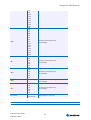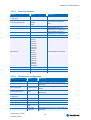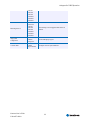
1
® Kontron User's Guide ® X-board™ <861> Document Revision 125 This page intentionally left blank Table of Contents Table of Contents 1 User Information........................................................................................................ 6 1.1 1.2 1.3 1.4 1.5 1.6 2 INTRODUCTION ........................................................................................................... 8 2.1 2.2 3 CPU and Chipset .............................................................................................. 13 System Memory .........................................................................................................14 5.1 6 Functional Specifications....................................................................................9 Mechanical Specifications ................................................................................. 10 Dimensions .................................................................................................... 10 Electrical Specifications.................................................................................... 10 Supply Voltage................................................................................................ 10 Supply Voltage Ripple ...................................................................................... 10 Supply Current (typical, DOS prompt) .................................................................. 10 CMOS Battery Power Consumption ...................................................................... 10 APM 1.2 Support ............................................................................................. 11 Environmental Specifications ............................................................................ 11 Temperature................................................................................................... 11 Humidity ....................................................................................................... 11 MTBF............................................................................................................. 11 CPU, Chipset, and Super I/O ........................................................................................13 4.1 5 X-board™ Benefits.............................................................................................8 X-board™ Documentation ...................................................................................8 Specifications ............................................................................................................ 9 3.1 3.2 3.2.1 3.3 3.3.1 3.3.2 3.3.3 3.3.4 3.3.5 3.4 3.4.1 3.4.2 3.5 4 About This Document .........................................................................................6 Copyright Notice ...............................................................................................6 Trademarks ......................................................................................................6 Standards ........................................................................................................6 Warranty .........................................................................................................6 Technical Support..............................................................................................7 SDRAM .......................................................................................................... 14 Interfaces ................................................................................................................15 6.1 6.2 6.3 6.3.1 6.4 PCI Bus.......................................................................................................... 15 LPC Bus ......................................................................................................... 15 IDE Ports ....................................................................................................... 15 Configuration ................................................................................................. 15 Serial ATA Signals............................................................................................ 15 Kontron User's Guide X-board™ <861> iii Table of Contents 6.5 6.5.1 6.6 6.6.1 6.7 6.7.1 6.8 6.8.1 6.9 6.9.1 6.10 6.11 6.12 6.13 6.13.1 6.14 6.14.1 6.15 6.15.1 6.16 6.16.1 7 Serial Ports (1 and 2) ....................................................................................... 15 Configuration ................................................................................................. 15 USB .............................................................................................................. 16 Configuration ................................................................................................. 16 Ethernet ........................................................................................................ 16 Configuration ................................................................................................. 16 AC’97 Codec Interface ...................................................................................... 16 Configuration ................................................................................................. 16 VGA Output .................................................................................................... 16 Configuration ................................................................................................. 17 Digital Flat Panel Interface (JIDI) ....................................................................... 17 Television Output ............................................................................................ 17 SMB/I2C BUS.................................................................................................. 18 Power Control................................................................................................. 18 Power Good / Reset Input ................................................................................. 18 Power Management ......................................................................................... 18 ATX PS Control ................................................................................................ 18 Miscellaneous Circuits ...................................................................................... 18 Battery.......................................................................................................... 18 Watchdog Timer .............................................................................................. 18 Configuration ................................................................................................. 18 Limitations ..............................................................................................................20 7.1 7.2 7.3 7.4 7.5 PCI ............................................................................................................... 20 Watchdog ...................................................................................................... 20 USB boot ....................................................................................................... 20 Keyboard / Mouse usage ................................................................................... 20 I²C Bus .......................................................................................................... 20 8 Appendix A: block diagram..........................................................................................21 9 Appendix B: System Resources ....................................................................................22 9.1 9.2 9.3 9.4 9.5 10 Interrupt Request (IRQ) Lines ............................................................................ 22 Direct Memory Access (DMA) Channels................................................................. 22 Memory Area .................................................................................................. 22 I/O Address Map ............................................................................................. 23 Peripheral Component Interconnect (PCI) Devices ................................................. 23 Appendix C: BIOS Operation ........................................................................................24 10.1 10.2 10.2.1 10.2.2 Determining the BIOS Version............................................................................ 24 Setup Guide ................................................................................................... 24 Start BIOS Setup Utility .................................................................................... 24 BIOS Setup Navigation ..................................................................................... 24 Kontron User's Guide X-board™ <861> iv Table of Contents 10.3 10.3.1 10.3.2 10.3.3 10.3.4 11 Appendix D: X-board connector pinouts ........................................................................34 11.1 12 JIDA Information ............................................................................................ 37 Appendix F: PC Architecture Information ......................................................................38 13.1 13.1.1 13.1.2 13.1.3 13.2 13.3 13.3.1 13.3.2 13.3.3 13.4 14 Signal Type designators.................................................................................... 36 Appendix E: JIDA STANDARD........................................................................................37 12.1 13 Main Menu ..................................................................................................... 25 Motherboard Device Configuration Submenu ........................................................ 25 Memory Optimization ....................................................................................... 30 Power Management ......................................................................................... 32 Miscellaneous Configuration.............................................................................. 32 Buses............................................................................................................ 38 Low Pin Count Bus (LPC) ................................................................................... 38 ISA, Standard PS/2 – Connectors........................................................................ 38 PCI/104......................................................................................................... 38 General PC Architecture .................................................................................... 38 Ports............................................................................................................. 39 RS-232 Serial ................................................................................................. 39 Serial ATA ...................................................................................................... 39 USB .............................................................................................................. 39 Programming ................................................................................................. 40 APPENDIX G: DOCUMENT-REVISION HISTORY ..................................................................41 Kontron User's Guide X-board™ <861> v 1 User Information 1 User Information 1.1 About This Document This document provides information about products from Kontron Embedded Modules GmbH and/or its subsidiaries. No warranty of suitability, purpose, or fitness is implied. While every attempt has been made to ensure that the information in this document is accurate, the information contained within is supplied “as-is” and is subject to change without notice. For the circuits, descriptions and tables indicated, Kontron assumes no responsibility as far as patents or other rights of third parties are concerned. 1.2 Copyright Notice Copyright © 2003-2007 Kontron Embedded Modules GmbH All rights reserved. No part of this document may be reproduced, transmitted, transcribed, stored in a retrieval system, or translated into any language or computer language, in any form or by any means (electronic, mechanical, photocopying, recording, or otherwise), without the express written permission of Kontron Embedded Modules GmbH. DIMM-PC®, PISA®, ETX®, ETXexpress® , X-board®, DIMM-IO® and DIMM-BUS® are trademarks or registered trademarks of Kontron Embedded Modules GmbH. Kontron is trademark or registered trademark of Kontron AG. 1.3 Trademarks The following lists the trademarks of components used in this board. 1.4 ® IBM, XT, AT, PS/2 and Personal System/2 are trademarks of International Business Machines Corp. ® Microsoft is a registered trademark of Microsoft Corp. ® Intel is a registered trademark of Intel Corp. ® All other products and trademarks mentioned in this manual are trademarks of their respective owners. Standards Kontron Embedded Modules GmbH is certified to ISO 9000 standards. 1.5 Warranty This Kontron Embedded Modules GmbH product is warranted against defects in material and workmanship for the warranty period from the date of shipment. During the warranty period, Kontron Embedded Modules GmbH will at its discretion decide to repair or replace defective products. Within the warranty period, the repair of products is free of charge as long as warranty conditions are observed. Kontron User's Guide X-board™ <861> 6 1 User Information The warranty does not apply to defects resulting from improper or inadequate maintenance or handling by the buyer, unauthorized modification or misuse, operation outside of the product’s environmental specifications or improper installation or maintenance. Kontron Embedded Modules GmbH will not be responsible for any defects or damages to other products not supplied by Kontron Embedded Modules GmbH that are caused by a faulty Kontron Embedded Modules GmbH product. 1.6 Technical Support Technicians and engineers from Kontron Embedded Modules GmbH and/or its subsidiaries are available for technical support. We are committed to making our product easy to use and will help you use our products in your systems. Before contacting Kontron Embedded Modules GmbH technical support, please consult our Web site at http://www.kontron-emea.com/emd for the latest product documentation, utilities, and drivers. If the information does not help solve the problem, contact us by telephone or email. Asia Europe North/South America Kontron Asia Inc. 4F, No.415, Ti-Ding Blvd., NeiHu District, Taipei 114, Taiwan Tel: +886 2 2799 2789 Fax: + 886 2 2799 7399 mailto:[email protected] Kontron Embedded Modules GmbH Kontron America Brunnwiesenstr. 16 94469 Deggendorf – Germany 14118 Stowe Drive Poway, CA 92064-7147 Tel: +49 (0) 991-37024-0 Fax: +49 (0) 991-37024-333 mailto:[email protected] Tel: +1 (888) 294 4558 Fax: +1 (858) 677 0898 mailto:[email protected] Kontron User's Guide X-board™ <861> 7 2 INTRODUCTION 2 INTRODUCTION 2.1 X-board™ Benefits The X-board™ modules of Kontron Embedded Modules GmbH are very compact (49mm x 68mm x 6mm) and highly integrated computers. All X-board™ modules have a standardized form factor and a standardized connector (DDR-SODIMM Memory Connector) that carries a specified set of signals. This standardization allows designers to create a single system “baseboard” which can accept a variety of present and future X-board™ modules. X-board™ modules include common personal computer (PC) peripheral functions such as serial ports, Ethernet, IDE, USB, etc. The baseboard designer can optimize exactly how each of these functions is physically implemented. Connectors can be placed precisely where they are needed for the application, on a baseboard designed to optimally fit the system configuration and layout. Legacy devices are omitted to reach a maximum in compactness and size. Peripheral PCI or LPC devices can be implemented directly on the baseboard rather than on mechanically unwieldy expansion cards. The ability to build a system on a single baseboard, using the computer as one “plug in” component, simplifies packaging, eliminates cabling, and significantly reduces systemlevel cost. A single baseboard design may be used with a range of X-board™ modules. This flexibility can be used to differentiate products at various price/performance points, or to design “future proof” systems that have a built-in upgrade path. The modularity of an X-board™ solution also insures against obsolescence as computer technology continues to evolve. A properly designed X-board™ baseboard can be used with several successive generations of X-board™ modules. An X-board™ baseboard design thus has many of the advantages of a custom computer board design, but delivers better obsolescence protection, greatly reduced engineering effort, and faster time to market. 2.2 X-board™ Documentation This manual is intended as one of three principal references for an X-board™ design. The X-board™ specification defines the X-board™ module form factor, pinout and signals. It is suggested that this be read first. The design guide is intended as a general guide for baseboard design, with a focus on maximum flexibility in order to accommodate a wide range of X-board™ modules. Finally, the technical manuals for specific X-board™ modules document the specifications and features of each individual X-board™ module. Kontron User's Guide X-board™ <861> 8 3 Specifications 3 Specifications 3.1 Functional Specifications Processor: National Semiconductor SC1200 Bus: 33MHz bus clock Chipset: National Semiconductor SC1200 Cache: 16KB integrated cache Onboard Memory: SDRAM with 32/64/128MB *Two Serial Ports (COM1 and COM2) ® COM 1 Transistor-to-transistor (TTL) signals only ® COM 2 (TTL) only two wires available (RXD, TXD) *This serial port configuration is only available from Product rev. X16 and BIOS rev. XBD1R112.ROM Enhanced Intelligent Drive Electronics (EIDE): One Peripheral Component Interconnect (PCI) Bus Master, IDE ports (up to two devices) support: ® Programmed Input/Output (PIO) modes up to Mode 4 timing ® Optional onboard IDE flash device with either 32/64/128MB Universal Serial Bus (USB) ® Three USB 1.1 ports (OHCI) ® USB legacy keyboard support ® USB floppy-boot support Low Pin Count Bus (LPC) Onboard Ethernet: · Intel 82551ER PCI single chip ® 10BASE-T/100BASE-T LAN ® Fast Ethernet NIC controller Onboard video graphics array (VGA): Integrated in National SC1200 ® 2D graphics accelerator and display controller ® Cathode ray tube (CRT) and liquid-crystal display (LCD) panel support: digital signals (JIDI) ® Resolution up to 1280 x 1024 x 8bpp (CRT) ® Resolution up to 1024 x 768 x 16bpp (CRT) Kontron User's Guide X-board™ <861> 9 3 Specifications ® Up to 4MB video RAM (UMA) ® TV Output (only available on BIOS revisions XBD1R113.rom and later) Audio: Integrated AC’97 Interface on National SC1200 ® AC’97 Interface to connect an AC’97 codec BIOS: Insyde, 512KB Flash BIOS ® BIOS support for external LPC super I/O (PS/2, COM3, COM4, LPT, and Floppy) NV-EEPROM for CMOS setup Watchdog timer (WDT) Real-time clock (requires an external battery) 3.2 Mechanical Specifications 3.2.1 Dimensions ® 49.0 mm x 68.0 mm ® Height approx. 6 mm 3.3 Electrical Specifications 3.3.1 Supply Voltage ® 3.3.2 Supply Voltage Ripple ® 3.3.3 3.3 VDC +/- 5% 100 mV peak to peak 0 - 20 MHz Supply Current (typical, DOS prompt) ® 900 mA It was measured with a board with 128 MB RAM and 128 MB onboard IDE flash connected in a backplane without additional power consuming components. 3.3.4 CMOS Battery Power Consumption RTC Integrated in AMD Geode SC 1200 Voltage Range Quiescent Current Max. Current 6.3 μA @ 2.4 V 2.4 V – 3.46 V 7.5 μA @ 3.0 V 50 μA @ TC=25 °C Data source: AMD Geode SC1200 datasheet revision 7.0 Kontron User's Guide X-board™ <861> 10 3 Specifications 3.3.5 APM 1.2 Support The X-board<861> supports APM 1.2 and has a standby and suspend state. Additionally during idle mode the board is in a low power state. This reduces the power tremendously when using operating systems that are able to switch the processor to idle mode (not DOS). The following table shows the current on the 3.3V line that powers the X-board<861>. Status Current Full On Idle Standby Suspend 890 mA 530 mA 480 mA 390 mA The measurements were done using a board with 32MB flash and 32MB RAM on a backplane without additional power draining components. The board was booted from a HDD with RedHat Linux including the APM Kernel. The Idle state was measured in console mode at the prompt. Resume is controlled by interrupts activated in the BIOS setup. This does not work in Windows 98 with PS/2 Mouse/Keyboard and with USB Mouse/Keyboard because Windows 98 deactivates the driver for PS/2 and USB during standby and suspend, which does not allow a resume. In Linux resume with USB Mouse/Keyboard is not possible. 3.4 Environmental Specifications 3.4.1 Temperature Note: 3.4.2 3.5 ® Operating: 0 to +62°C ® Non operating: -40 to +85°C The maximum operating temperature is the maximum measurable temperature on any spot on a module’s surface. You must maintain the temperature according to the above specification. For more information about cooling solutions please contact Kontron Embedded Modules. Humidity ® Operating: 10% to 90% (non condensing) ® Non operating: 5% to 95% (non condensing) MTBF The following MTBF (Mean Time Between Failure) values were calculated using a combination of manufacturer’s test data, if the data was available, and a Bellcore calculation for the remaining parts. The Bellcore calculation used is “Method 1 Case 1”. In that particular method the components are assumed to be operating at a 50 % stress level in a 40° C ambient environment and the system is assumed to have not been burned in. Manufacturer’s data has been used wherever possible. The manufacturer’s data, when used, is specified at 50° C, so in that sense the following results are slightly Kontron User's Guide X-board™ <861> 11 3 Specifications conservative. The MTBF values shown below are for a 40° C in an office or telecommunications environment. Higher temperatures and other environmental stresses (extreme altitude, vibration, salt water exposure, etc.) lower MTBF values. System MTBF (hours) : 266.570 Notes: Fans usually shipped with Kontron Embedded Modules GmbH products have 50,000-hour typical operating life. The above estimates assume no fan, but a passive heat sinking arrangement. Estimated RTC battery life (as opposed to battery failures) is not accounted for in the above figures and need to be considered for separately. Battery life depends on both temperature and operating conditions. When the Kontron unit has external power; the only battery drain is from leakage paths. Kontron User's Guide X-board™ <861> 12 4 CPU, Chipset, and Super I/O 4 CPU, Chipset, and Super I/O 4.1 CPU and Chipset The central processing unit (CPU) and the Chipset (North and South bridge) consists of a National Semiconductor SC1200 and is available at a speed of 266MHz. Features include: ® Support for Intel’s MMX instruction set extension for acceleration of multimedia applications (one pipeline) ® 16KB unified L1 cache ® PCI host controller ® 2D graphics accelerator and display controller ® SDRAM interface tightly coupled to CPU core and graphics subsystem for maximum efficiency ® Provides 16-bit Xpress AUDIO subsystem, AC’97 Interface ® 3.3V PCI bus compatible ® PCI 2.1 compliant ® PCI master for audio I/O and IDE controllers ® Two 8259A-equivalent interrupt controllers ® 8254-equivalent timer ® Two 8237-equivalent DMA controllers ® Boot ROM chip select ® One controller with support for up to two IDE devices ® Independent timing for master and slave devices ® AC97 codec interface (Specification Revision 2.0 compliant interface) ® Three independent USB interfaces. Open Host Controller Interface (OpenHCI) specification compliant Kontron User's Guide X-board™ <861> 13 5 System Memory 5 System Memory 5.1 SDRAM The X-board<861> uses onboard-unbuffered Synchronous Dynamic Random Access Memory (SDRAM) sizes of 32, 64 or 128MB. Kontron User's Guide X-board™ <861> 14 6 Interfaces 6 Interfaces 6.1 PCI Bus The implementation of this subsystem complies with the X-board™ Specification. Implementation information is provided in the X-board™ Design Guide. Refer to the documentation for additional information. 6.2 LPC Bus The implementation of this subsystem complies with the X-board™ Specification. Implementation information is provided in the X-board™ Design Guide. Refer to the documentation for additional information. The LPC Bus is the subtractive decoding agent in this system, i.e. all I/O and memory accesses, which don’t belong to onboard RAM, internal chipset devices, onboard Super I/O or PCI devices, are linked to the LPC bus. Note: 6.3 *If the LPC interface is not used on the customers backplane, then the signals LAD[0..3] and LDRQ# have to be connected together and pulled-up to 3.3V with an 15kΩ resistor. IDE Ports The implementation of this subsystem complies with the X-board™ Specification. Implementation information is provided in the X-board™ Design Guide. Refer to those documents for additional information. 6.3.1 Configuration The IDE host adapter is a PCI bus device. BIOS configures it during PCI device configuration. You can disable it by using the BIOS setup. Resources used by the IDE host adapter are compatible with the PC/AT. 6.4 Serial ATA Signals Serial ATA is not supported by X-board<861> 6.5 Serial Ports (1 and 2) The implementation of the serial-communication interface is restricted. COM1 supports TxD, RxD, #RTS, #DTR, #CTS, #DCD, #DSR, #RI, and COM2 only supports RXD and TXD. Implementation information is provided in the X-board™ Design Guide. Refer to the documentation for additional information. 6.5.1 Configuration The serial-communication interface uses I/O and IRQ resources. The resources are allocated by BIOS during POST configuration and are set to be compatible with common PC/AT settings. Use the BIOS setup to change some parameters that relate to the serial-communication interface. Kontron User's Guide X-board™ <861> 15 6 Interfaces 6.6 USB Three OHCI-type USB host controllers are on the National SC1200 single chip processor. The USB controllers comply with Version 1.1 of the USB standard. The implementation of this subsystem complies with the X-board™ Specification. Implementation information is provided in the X-board™ Design Guide. Refer to those documents for additional information. 6.6.1 Configuration The USB controllers are PCI bus devices. BIOS allocates required system resources during configuration of the PCI bus. 6.7 Ethernet The 82551ER is a fully integrated, cost-effective 10BASE-T/100BASE-TX LAN solution. It is designed for low-power use and high-performance processes. It is a 3.3V device with 5V tolerance and supports 3.3V and 5V signaling. 6.7.1 Configuration The Ethernet interface is a PCI device. The BIOS setup automatically configures it. Note: 6.8 The Ethernet interface works according to the common criteria of the embedded technology market segment. AC’97 Codec Interface The sound function on the X-board<861> board comes from the AC’97 interface of the National Semiconductor’s SC1200. An external Codec must be connected on the baseboard to use the audio functions. Please look at the implementation information provided in the X-board™ Design Guide. 6.8.1 Configuration The audio controller is a PCI bus device. BIOS allocates required system resources during configuration of the PCI device. 6.9 VGA Output The National SC1200 includes the display subsystem: Video accelerator ® Buffers and formats input YUV video data from processor ® 8-bit interface ® X & Y scaler with bilinear filter ® Color space converter (YUV to RGB) Display Interface ® Integrated RGB video DACs Kontron User's Guide X-board™ <861> 16 6 Interfaces ® VESA DDC2B/DPMS support ® Flat-panel interface ® Brightness and contrast control Supported Resolutions for CRT ® Up to 1024 x 768 x 16bpp (64k colors) ® 1280 x 1024 x 8bpp (256 colors) Supported Resolutions for LCD (JIDI) ® With LVDS transceiver on the backplane: ® Only TTL signals: up to 1024 x 768 x 16bpp (64k colors) up to 640 x 480 x 16bpp (64k colors) Simultaneous Resolution Mode (CRT and LCD) ® Up to 800 x 600 x 16bpp TV Output Support ® 6.9.1 PAL and NTSC composite 640 x 480 (only available on BIOS revisions XBD1R113.rom and later) Configuration The graphics controller requires the following resources: ® An IRQ ® Several I/O addresses ® Memory-address blocks in high memory BIOS allocates the resources during AGP configuration. Many resources are set for compatibility with industry-standard settings. 6.10 Digital Flat Panel Interface (JIDI) Optionally, the X-board<861> supports the JUMPtec Intelligent Digital Interface (JIDI). It provides the possibility to store controller specific panel configuration data in an external eeprom. It additionally allows to store the panel ID regarding the JILI3 specification. As a special feature also this panel ID can be directly keyed in the BIOS setup. Therefore an external EEPROM on the panel interface is no longer necessary. Please contact Kontron Embedded Modules Technical Support for more information. 6.11 Television Output The X-board<861> supports television output (only available on BIOS revisions XBD1R113.rom and later). Standard PAL and NTSC composite output supported. Kontron User's Guide X-board™ <861> 17 6 Interfaces 6.12 SMB/I2C BUS The X-board<861> provides only the I²C bus on that interface. 6.13 Power Control 6.13.1 Power Good / Reset Input The X-board<861> provides an external input for a power good signal or a manual reset pushbutton. The implementation of this subsystem complies with the X-board™ Specification. Implementation information is provided in the X-board™ Design Guide. Refer to those documents for additional information. 6.14 Power Management 6.14.1 ATX PS Control The X-board <861> can control the main power output of an ATX-style power supply. The implementation of this subsystem complies with the X-board™ Specification. Implementation information is provided in the X-board™ Design Guide. Refer to those documents for additional information. 6.15 Miscellaneous Circuits 6.15.1 Battery The implementation of the battery input complies with the X-board™ Specification. Implementation information is provided in the X-board™ Design Guide. Refer to those documents for additional information. 6.16 Watchdog Timer This feature is implemented in National SC1200. You can configure the Watchdog Timer (WDT) from the BIOS setup to start after a set amount of time following power-on boot. The WDT can also be controlled by the JIDA32 Library API (Refer to Appendix E: JIDA STANDARD). The application software should strobe the WDT to prevent its timeout. Upon timeout, the WDT resets and restarts the system. This provides a way to recover from program crashes or lockups. 6.16.1 Configuration You can program the initial delay period for the WDT in ranges from 000000h * 0,256 sec to 07FFFh * 0,256 Sec. You can also program the timeout period for the WDT in ranges from 000000h * 0,256 sec to 07FFFh * 0,256 Sec. Contact Kontron Embedded Modules for information about programming and operating the WDT. Strap Pins ® AC97_Sync (Pin 11), 1k5 to GND Kontron User's Guide X-board™ <861> 18 6 Interfaces ® AC97_DOUT (Pin 5), 1k5 to 3.3V supply ® COM1_TxD (Pin 51), 1k5 to GND ® COM2_TxD (Pin 65), 1k5 to 3.3V supply ® GNT1# (Pin 181), 1k5 to GND ® GNT0# (Pin 185), 1k5 to GND During the power-up sequence of the X-board <861> several signals are read that set up the state of the SC1200/SC1201 (chipset). These particular signals are usually multiplexed with other functions that result in outputs after the power-up sequence is completed. While powering up, the X-board <861> has to read the current state of the signals and yet the internal PU or PD resistors don’t necessarily guarantee that the correct state will be read. For this reason it is essential that an external PU or PD resistor with a value of 1.5 KΩ be placed on the signals listed above. Kontron Embedded Modules has implemented this in their X-board <861> design. The X-board <861> user must ensure that they do not alter the signals mentioned above in any way. The value of the resistor is extremely important so that the proper state is read during the power-up sequence. If the ball produces an incorrect reading during power-up then the X-board <861> may default to a state that causes it to function improperly, which could result in undesired behavior such as an application failure. This table shows the values that must be maintained when using an external PU or PD. (extracted from National/AMD chipset datasheets page 378) Symbol Parameter Min Max Unit VIH Input High Voltage 0.6VIO VIO+0.5 V VIL Input Low Voltage 0.3VIO V 36 μA During Reset VIN = VIO IIL Input Leakage Current -10 μA VIN = VSS Kontron User's Guide X-board™ <861> 19 Comments 7 Limitations 7 Limitations 7.1 PCI GNT1#/REQ1# are used by Ethernet, therefore not available for external PCI devices. 7.2 Watchdog The Watchdog only allows RESET, no NMI operation. 7.3 USB boot USB CD-ROM and USB hard disk boot support. Access to USB hard disk is not possible if the USB hard disk is not the boot device. 7.4 Keyboard / Mouse usage You can either use a USB mouse and keyboard, or a PS/2 mouse and keyboard. Once a USB mouse or USB keyboard is plugged in, PS/2 devices are disabled. 7.5 I²C Bus The I²C bus is also used for JILI/JIDI devices, therefore there may be additional devices (JILI Data EEPROM, Backlight DAC) reducing the number of available addresses. Please refer to the JILI manual to find out which addresses may not be available. Kontron User's Guide X-board™ <861> 20 8 Appendix A: block diagram 8 Appendix A: block diagram X-board<861> BIOS Flash Memory DRAM EEPROM Setup Data 100BaseT Ethernet Controller CPU PCI Ethernet 82551ER Onboard Flash Disk (Sandisk) National SC1200 LPC IDE I2C AC'97 TV CRT LCD USB1-3 COM1COM2 X-board Connector Kontron User's Guide X-board™ <861> 21 9 Appendix B: System Resources 9 Appendix B: System Resources 9.1 Interrupt Request (IRQ) Lines IRQ # Used For Available 0 1 2 3 4 5 6 7 8 9 10 11 12 13 14 15 Timer0 LPC (Keyboard Controller) Cascade COM2 COM1 Sound LPC (Floppy Controller) LPC (LPT) RTC PCI (default for INT A) PCI (default for INT B) PCI (default for INT D) LPC (PS/2 Mouse) FPU IDE0 PCI; LPC No No No No No No No No No Yes Yes Yes No No No Yes Notes: Comment Note (1) Note (1) Note (1) Note (1,2) Note (1,2) Note (3) Note (3) Note (2) Note (1) 1 If the “Used For” device is disabled in setup or not connected on the backplane, the corresponding interrupt is available for other devices. 2 In use if the baseboard is equipped with I/O controller PC87365. 3 If not used for PCI it is routed to LPC (available for COM3 and COM4) 9.2 Direct Memory Access (DMA) Channels DMA # Used for Available 0 1 2 3 4 5 6 7 LPC Sound 8-bit FDC LPT Cascade Sound 16-bit Yes No No No No No Yes Yes Note: 9.3 1 Comment Note (1) Note (1) Unavailable if LPT used in ECP mode. Note (1) If the “Used For” device is disabled in setup, the corresponding interrupt is available for other devices. Memory Area Upper Memory Used for Available Comment C0000h – C8000h C8000h – CFFFFh D0000h – DFFFFh VGA BIOS USB-boot ROM UMB No No No Shadow RAM Kontron User's Guide X-board™ <861> 22 9 Appendix B: System Resources E0000h - FFFFFh System BIOS No All memory accesses above TOP_OF_MEMORY (=installed RAM), if not explicitly noted below, are available for PCI or LPC bus devices (PCI positive decoding takes precedence). Details/Special Devices: The BIOS will map all PCI memory areas above 40000000h; thus memory from TOP_OF_RAM to 40000000h (1GB) will be exclusively available for LPC devices. 9.4 I/O Address Map The I/O-port addresses of the X-board<861> are functionally identical with a standard PC/AT. PC/AT Standard I/O addresses should be assumed to be used. LPC devices should not try to map (use) I/O addresses below 400h, unless it is an LPC Super I/O, which implement legacy PC hardware like COM, LPT, Floppy or Keyboard/Mouse. The following I/O ports >400h are used by the chipset and onboard resources: I/O Address Used for Available 0480h - 048Fh chipset internal Interrupt sensitivity configuration registers (standardized) chipset internal PCI configuration registers chipset internal chipset internal chipset internal chipset internal chipset internal chipset internal chipset internal No 04D0h - 04D1h 0860h - 086Fh 0CF0h - 0CFFh 5000h - 500Fh 6000h - 60FFh 6200h - 623Fh 6400h - 643Fh 6600h - 663Fh 9000h - 90FFh 9C00h - 9CFFh 9.5 Comment No No No No No No No No No No Peripheral Component Interconnect (PCI) Devices PCI Device PCI Interrupt Comment Sound Ethernet Graphic USB Controller INTC (internal) INTA no no Chipset integrated, no REQ/GNT pairs used Use REQ1/GNT1 pair No use of an internal REQ/GNT pair. No use of an internal REQ/GNT pair You can use only REQ0/GNT0 pair for external PCI devices. In the X-board™ Design Guide you find additional information about how to expand these pairs by using certain devices on the backplane Only INTA and INTB are externally available. Kontron User's Guide X-board™ <861> 23 10 Appendix C: BIOS Operation 10 Appendix C: BIOS Operation The Module is equipped with an Insyde XpressROM™ BIOS, which is located in an onboard Flash EEPROM. You can update the BIOS using a Flash utility. 10.1 Determining the BIOS Version To determine the BIOS version, the summery screen in the BIOS setup must be activated. The information is located in the summery screen (marked here with a red arrow): 10.2 Setup Guide The Insyde BIOS Setup Utility changes system behavior by modifying the BIOS configuration. The setup program uses a number of menus to make changes and to turn features on or off. The BIOS setup menus documented in this section represent those found in most models of the Xboard<861>. The BIOS Setup for specific models can differ slightly. 10.2.1 Start BIOS Setup Utility To start the setup utility, press <F1> during boot up when the following string appears. Press F1 to enter Setup The Main Menu then appears. 10.2.2 BIOS Setup Navigation Navigation through the setup can be done either by using the cursor keys ← or →and ↑ or ↓, or by pressing the character keys that are shown in front of every menu item. A menu item is either a field for selecting and changing an entry or a submenu. To change an entry, or to jump into a submenu, press the enter key <ENTER>. To jump back from a submenu press the <ESC> key. In the option column, bold shows the BIOS default values. Kontron User's Guide X-board™ <861> 24 10 Appendix C: BIOS Operation 10.3 Main Menu Character Feature Option Description A B Time Date Motherboard Device Configuration Memory Optimization Power Management Miscellaneous Configuration Load Defaults Saves Values Without Exit Exit Without Save Save Values and Exit HH:MM:SS MM/DD/YYYY Set the system time Set the system date C D* F H L S Q X Note: Submenu for Device Configuration Submenu for memory timing control Submenu for Power Management Submenu for Miscellaneous Configuration Loads the setup defaults Save all values and stay in Setup Utility Quit Setup Utility without saving the changes Saves all changes and exit Setup Utility * This feature is only available on X-board <861> modules that have BIOS revision XBD1R112.rom or later. 10.3.1 Motherboard Device Configuration Submenu Character Feature Description A B Drive Configuration Onboard Super I/O Configuration LPC Bus & LPC Super I/O Configuration TV Output Configuration Legacy Audio Configuration Video and Flat Panel Configuration PCI Configuration Return to Main Page Submenu for Drive Configuration Submenu for Super I/O Configuration C* D** E F G R Note: Submenu for LPC Bus & LPC Super I/O Configuration Submenu for TV Output Submenu for Audio Configuration Submenu for Video and Flat Panel Configuration Submenu for PCI Configuration Returns to Main Menu * This feature is only available on X-board <861> modules that have BIOS revision XBD1R112.rom or later. **This feature is only available on X-board <861> modules that have BIOS revision XBD1R113.rom or later. Drive Configuration Feature Option Description Primary Disabled Auto PIO0 PIO1 PIO2 PIO3 PIO4 Auto PIO0 PIO1 PIO2 Switch the single IDE channel ON and OFF IDE Configuration Chipset IDE Channel Max PIO mode for Drive 1 Max PIO mode for Drive 2 Kontron User's Guide X-board™ <861> Switches on the maximum transfer mode of the IDE Drive 1 Switches on the maximum transfer mode of the IDE Drive 2 25 10 Appendix C: BIOS Operation PIO3 PIO4 Boot ROM Configuration CD-ROM Boot-ROM USB Mass Storage Boot-ROM PXE Lanboot Option ROM Enabled Disabled Enabled Disabled Enabled Flag Controlled Disabled Enable and Disable the possibility to boot from IDE CD-ROM devices Enable and Disable the possibility to boot from USB Mass Storage devices Enable and Disable the possibility to boot from LAN Boot Order Configuration 1. 2. 3. 4. 5. 6. Kontron User's Guide X-board™ <861> Floppy Disk Hard Drive #1 Hard Drive #2 USB Mass Storage IDE-CDROM Drive None Network Boot Floppy Disk Hard Drive #1 Hard Drive #2 USB Mass Storage IDE-CDROM Drive None Network Boot Floppy Disk Hard Drive #1 Hard Drive #2 USB Mass Storage IDE-CDROM Drive None Network Boot Floppy Disk Hard Drive #1 Hard Drive #2 USB Mass Storage IDE-CDROM Drive None Network Boot Floppy Disk Hard Drive #1 Hard Drive #2 USB Mass Storage IDE-CDROM Drive None Network Boot Floppy Disk Hard Drive #1 Hard Drive #2 USB Mass Storage IDE-CDROM Drive None Network Boot Selects the 1st boot device Selects the 2nd boot device Selects the 3rd boot device Selects the 4th boot device Selects the 5th boot device Selects the 6th boot device 26 10 Appendix C: BIOS Operation 5. Floppy Disk Hard Drive #1 Hard Drive #2 USB Mass Storage IDE-CDROM Drive None Network Boot Selects the 7th boot device Onboard Super I/O Configuration Feature Serial Port A Serial Port B Option 0x3f8 IRQ 4 0x2f8 IRQ 3 0x3e8 IRQ 4 0x2e8 IRQ 3 Disabled 0x3f8 IRQ 4 0x2f8 IRQ 3 0x3e8 IRQ 4 0x2e8 IRQ 3 Disabled Description Selects the resources of 1st onboard serial port Selects the resources of 2nd onboard serial port LPC Bus & LPC Super I/O Configuration Feature LPC Bus* Serial Port 1 Serial Port 2 Parallel Port Mode IRQ DMA Kontron User's Guide X-board™ <861> Option Description Enabled Disabled 0x3f8 IRQ 4 0x2f8 IRQ 3 0x3e8 IRQ 4 0x2e8 IRQ 3 Disabled 0x3f8 IRQ 4 0x2f8 IRQ 3 0x3e8 IRQ 4 0x2e8 IRQ 3 Disabled Enable or disable the complete LPC bus (including LPC Super I/O). 0x378 0x278 0x3bc Disabled Compatible PS/2 Bidirectional EPP 1.7 EPP 1.9 IRQ 7 Disabled IRQ 5 None Channel 3 Channel 1 Selects the resources of 1st LPC serial port Selects the resources of 2nd LPC serial port Selects the resources of 2nd onboard serial port Sets the Mode for the Parallel Port Sets the IRQ for the Parallel Port Sets the DMA Channel for the Parallel Port 27 10 Appendix C: BIOS Operation Note: * This feature is only available on X-board <861> modules that have BIOS revision XBD1R112.rom or later. TV Output Configuration Feature Option Mode Disabled Composite PAL NTSC 640x480 Horizontal Position 0-255 TV Output Format Note: Description Enables the Composite output Selects format for TV Output Only resolution available Allows you to center image on TV screen. Each increment moves the image 1 character (8 pixels) to the right. This feature is only available on X-board <861> modules that have BIOS revision XBD1R113.rom or later. Legacy Audio Configuration Feature Audio Enable Audio Base Audio IRQ Audio 8-bit DMA Audio 16-bit DMA Option Disabled Enabled 0x220 0x240 0x260 0x280 IRQ 5 IRQ 7 IRQ 9 IRQ 10 Disabled Channel 1 Channel 3 Channel 5 Disabled Channel 0 Channel 1 Channel 3 Channel 5 Disabled Channel 0 Description Enables the Legacy Audio Interface Selects the I/O Address of the Audio Interface Selects the IRQ of the Audio Interface Sets the DMA Channel for 8-bit audio transfers Sets the DMA Channel for 16-bit audio transfers Video and Flat Panel Configuration Feature Option Description Video Memory 4 MB None 1,0 MB 1,5 MB 2,0 MB 2,5 MB 3,0 MB Selects the size of Video Memory. This value is reducing the RAM Kontron User's Guide X-board™ <861> 28 10 Appendix C: BIOS Operation Flat Panel Mode Flat Panel Type Panel ID 3,5 MB Enabled Disabled Auto Detect Use Panel ID 640x480 800x600 1024x768 00000 Enables and disables the flat panel interface Switches between usage of I²C EEPROM, fixed Panel ID in setup or standard settings for common panels Flat panel ID to be used without EEPROM directly to set in the setup Backlight Configuration Brightness Control Initial Brightness Disabled Enabled Last Value 0% (OFF) 10% … 90% 100% (Full ON) Enable and disable the Control of DACs on the I²C bus to control the brightness via JIDA Disabled Enabled Last Value 0% (OFF) 10% … 90% 100% (Full ON) Enables or disables the Control of DACs on the I²C bus to control the contrast via JIDA Option Description Select the initial brightness of the backlight, if it is controlled via JIDA on the I²C bus Contrast Configuration Contrast Control Initial Contrast Selects the initial contrast of the STN panel, if it is controlled via JIDA on the I²C bus PCI Configuration Feature PCI INTA# PCI INTB# Kontron User's Guide X-board™ <861> IRQ 9 IRQ 10 IRQ 11 IRQ 12 IRQ 14 IRQ 15 Disabled IRQ 3 IRQ 4 IRQ 5 IRQ 6 IRQ 7 IRQ 9 IRQ 10 IRQ 11 IRQ 12 IRQ 14 IRQ 15 Fixes an interrupt to PCI INT line A Fixes an interrupt to PCI INT line B 29 10 Appendix C: BIOS Operation PCI INTC# PCI INTD# Disabled IRQ 3 IRQ 4 IRQ 5 IRQ 6 IRQ 7 IRQ 9 IRQ 10 IRQ 11 IRQ 12 IRQ 14 IRQ 15 Disabled IRQ 3 IRQ 4 IRQ 5 IRQ 6 IRQ 7 IRQ 9 IRQ 10 IRQ 11 IRQ 12 IRQ 14 IRQ 15 Disabled IRQ 3 IRQ 4 IRQ 5 IRQ 6 IRQ 7 Fixes an interrupt to PCI INT line C (exclusively used by chipset integrated audio controller). Fixes an interrupt to PCI INT line D (exclusively used by chipset integrated audio controller). 10.3.2 Memory Optimization Feature Memory Optimization* SDRAM Bus Frequency* CAS latency* tRC* Kontron User's Guide X-board™ <861> Option Description Auto Manual 106MHz 88MHz 75MHz 66MHz 60MHz 2 Clk 3 Clk 4 Clk 5 Clk 6 Clk 7 Clk 2 Clk 3 Clk 4 Clk 5 Clk 6 Clk 7 Clk Select memory timing auto configuration or manual selection. Select base SDRAM bus clock. Select CAS latency. For Kontron customization only. Do not change. 30 10 Appendix C: BIOS Operation 8 Clk 9 Clk 10 Clk 11 Clk 12 Clk 13 Clk 14 Clk 15 Clk 16 Clk 2 Clk 3 Clk 4 Clk 5 Clk 6 Clk 7 Clk 8 Clk 9 Clk 10 Clk 11 Clk 12 Clk 13 Clk 14 Clk 15 Clk 16 Clk 2 Clk 3 Clk 4 Clk 5 Clk 6 Clk 7 Clk 2 Clk 3 Clk 4 Clk 5 Clk 6 Clk 7 Clk 0...7 1 tRAS* tRP* tRCD* tRRD* tDPL* Cache Mode* Note: 2 Clk 3 Clk 4 Clk 5 Clk 6 Clk 7 Clk Write-Back Write-Through For Kontron customization only. Do not change. For Kontron customization only. Do not change. For Kontron customization only. Do not change. For Kontron customization only. Do not change. For Kontron customization only. Do not change. Select desired L1 cache mode. * This feature is only available on X-board <861> modules that have BIOS revision XBD1R112.rom or later. Kontron User's Guide X-board™ <861> 31 10 Appendix C: BIOS Operation 10.3.3 Power Management Feature Option Description Legacy & APM Disabled Legacy Selects the Power Management Mode Power Management Configuration Power Management Mode Wakup Mask Configuration Wakeup Mask PIC1 0x12 Wakeup Mask PIC2 0x10 Selects the Interrupts 0-7 by Hexadecimal no. as wakeup event Selects the Interrupts 8-15 by Hexadecimal no. as wakeup event Timeout Configuration Video Timeout Standby Timeout Suspend Timeout Harddisk Timeout Disabled 1 Second 5 Seconds 10 Seconds 15 Seconds 30 Seconds 45 Seconds 1 Minute 5 Minutes 10 Minutes 15 Minutes 30 Minutes 45 Minutes 60 Minutes 90 Minutes 120 Minutes See Video Timeout See Video Timeout See Video Timeout Time till the Video is switched off Time till standby mode Time till suspend mode Time till HDD is switched off 10.3.4 Miscellaneous Configuration Feature Option Description Splash Screen Configuration Splash Screen Enabled Disabled Clear Splash Screen Enabled Disabled Splash Screen Timeout 00000 Summary Screen Configuration Summary Screen Summary Screen Timeout Watchdog Configuration Watchdog Watchdog Delay Kontron User's Guide X-board™ <861> Enabled Disabled 00100 Disabled Reset 10 Seconds 30 Seconds Enables or disables the splash screen during boot (boot logo) Enables or disables clearing of splash screen after display Time until splash screen times out. Set in milliseconds Enables or disables the summary screen Time until summary screen times out in milliseconds Sets the watchdog mode The watchdog will only start to count down after the given delay 32 10 Appendix C: BIOS Operation Watchdog Timeout Legacy USB Configuration Customer ROM Kontron User's Guide X-board™ <861> 1 Minute 2 Minutes 5 Minutes 10 Minutes 15 Minutes 30 Minutes 10 Seconds 30 Seconds 1 Minute 2 Minutes 5 Minutes 10 Minutes 15 Minutes 30 Minutes Enabled Disabled During Post Disabled Enabled Flag Controlled The watchdog must be triggered within this time interval Control USB legacy support Configure customer option ROM start 33 11 Appendix D: X-board connector pinouts 11 Appendix D: X-board connector pinouts Pin number Signal Signal type Pin number Signal Signal type 1 3 5 7 9 11 13 15 17 19 21 23 25 27 29 31 33 35 37 39 41 43 45 47 49 51 53 55 57 59 61 63 65 67 69 71 73 75 77 79 81 83 85 87 89 91 BUZZER Codec_AC97_CLK Codec_SDATA_OUT Codec_SDATA_IN Codec_BIT_CLK Codec_SYNC Codec_RESET# GND Lan TXLan TX+ Lan RXLan RX+ Lan LNLED# Lan LNKLED# 3.3V USB[1]+ USB[1]Overcurrent# USB[2]+ USB[2]GND DCD1# DSR1# RXD1 RTS1# TXD1 CTS1# DTR1# RI1# 3.3V RXD2 NC TXD2 NC 3.3V Spare GND NC NC NC NC GND AD[00] AD[01] AD[02] AD[03] O1 O1 O1 I1 II O1 O1 P O2 O2 O2 O2 O3 O3 P OUSB OUSB I3 OUSB OUSB P I1 I1 I4 O1 O4 I1 O1 I1 P I4 O4 P P P I/O I/O I/O I/O 2 4 6 8 10 12 14 16 18 20 22 24 26 28 30 32 34 36 38 40 42 44 46 48 50 52 54 56 58 60 62 64 66 68 70 72 74 76 78 80 82 84 86 88 90 92 PWRGOOD_IN V_BATT TV CP OUT GND CRT-R CRT-G CRT-B GND CRT-HSYNC CRT-VSYNC 3.3V TFT-R5 TFT-R4 TFT-R3 TFT-R2 TFT-R1 TFT-R0 GND TFT-G5 TFT-G4 TFT-G3 TFT-G2 TFT-G1 TFT-G0 3.3V TFT-B5 TFT-B4 TFT-B3 TFT-B2 TFT-B1 TFT-B0 GND TFT-HSYNC TFT-VSYNC TFT-DE TFT-SCLK GND NC DIGON 3.3V 3.3V-Standby Power Button# Internal use NC NC NC I2 P2 OA P OA OA OA P O1 O1 P O1 O1 O1 O1 O1 O1 P O1 O1 O1 O1 O1 O1 P O1 O1 O1 O1 O1 O1 P O1 O1 O1 OPC P O1 P P I7 Kontron User's Guide X-board™ <861> 34 - - 11 Appendix D: X-board connector pinouts 93 95 97 99 101 103 105 107 109 111 113 115 117 119 121 123 125 127 129 131 133 135 137 139 141 143 145 147 149 151 153 155 157 159 161 163 165 167 169 171 173 175 177 179 181 183 185 187 189 191 193 AD[04] AD[05] AD[06] AD[07] AD[08] C/BE[0]# AD[09] AD[10] AD[11] AD[12] AD[13] AD[14] C/BE[1]# AD[15] LOCK# PERR# DEVSEL# SERR# STOP# NC TRDY# IRDY# FRAME# AD[16] C/BE[2]# AD[17] PAR AD[18] AD[19] AD[20] AD[21] AD[22] AD[23] C/BE[3]# AD[24] AD[25] AD[26] AD[27] AD[28] AD[29] AD[30] NC AD[31] REQ1# (used by onboard Ethernet) GNT1# (used by onboard Ethernet) REQ0# GNT0# RST# CLK0 CLK1 CLK2 Kontron User's Guide X-board™ <861> I/O I/O I/O I/O I/O I/O I/O I/O I/O I/O I/O I/O I/O I/O I/O1 I/O1 I/O1 I/O1 I/O1 I/O1 I/O1 I/O I/O I/O I/O I/O1 I/O I/O I/O I/O I/O I/O I/O I/O I/O I/O I/O I/O I/O I/O I/O I6 O4 I6 O4 O1 O1 O1 O1 35 94 96 98 100 102 104 106 108 110 112 114 116 118 120 122 124 126 128 130 132 134 136 138 140 142 144 146 148 150 152 154 156 158 160 162 164 166 168 170 172 174 176 178 180 182 184 186 188 190 192 194 PS_ON# NC GND LAD[3] * LAD[2] * LAD[1] * LAD[0] * LDRQ# * LFRAME# LPCPD# SERIRQ# 3.3V USB[3]+ USB[3]3.3V I²C_CLK I²C_DAT GND IDE_DASP IDE_PDIAG 3.3V IDE_CS3# IDE_CS1# IDE_A2 IDE_A0 IDE_A1 GND IDE_INTRQ IDE_AK# IDE_RDY IDE_IOR# IDE_IOW# IDE_DRQ GND IDE_D0 IDE_D1 IDE_D2 IDE_D3 IDE_D4 3.3V IDE_D5 IDE_D6 IDE_D7 IDE_D8 IDE_D9 IDE_D10 GND IDE_D11 IDE_D12 IDE_D13 IDE_D14 O5 P I/O I/O I/O I/O I4 O1 O1 I/O1 P OUSB OUSB P I/O2 I/O2 P I/O3 I/O3 P I/O1 I/O1 I/O1 I/O1 I/O1 P I8 I/O1 I/O1 I/O1 I/O1 I/O1 P I/O1 I/O1 I/O1 I/O1 I/O1 P I/O1 I/O1 I/O1 I/O1 I/O1 I/O1 P I/O1 I/O1 I/O1 I/O1 11 Appendix D: X-board connector pinouts 195 197 199 Note: 11.1 CLK3 INTA# INTB# I6 I6 196 198 200 IDE_D15 HDRST# GND I/O1 O6 P * If the LPC interface is not used on the customers backplane, then the signals LAD[0..3] and LDRQ# have to be connected together and pulled-up to 3.3V with an 15kΩ resistor. Signal Type designators ® I1 Input, TTL compatible. ® I2 Input, low active with open collector/button. ® I3 (15kΩ). Input, TTL compatible with Schmitt-Trigger. Internally pulled up ® I4 Input, TTL compatible. Internally pulled up (15kΩ). ® I5 Input, TTL compatible. Internally pulled down (15kΩ). ® I6 Input, TTL compatible. Internally pulled up (6,8KΩ). ® I7 Input, TTL compatible with Schmitt-Trigger and 16ms debounce. Internally pulled up (15kΩ). ® I8 Inpul, TTL compatible. Internally pulled up (10kΩ). ® O1 Output 3,3V (3,14V-3,46V), source 2mA, sink 5mA. ® O2 Output, differential pair. ® O3 Output, open collector. 5V tolerant. ® O4 Output. Do not pull up or down externally! ® O5 Output. Internally pulled up (15kΩ). ® O6 Output. Internally pulled down (1kΩ). ® OA Output, analog. ® OUSB Output. Internally pulled down (15kΩ). ® OPC Clock Output. Target impedance 70Ω. ® I/O Input/Output. ® I/O1 Input/Output. Internally pulled up (6,8kΩ). ® I/O2 Input/Output. Internally pulled up (10kΩ). ® I/O3 Input/Output (see X-board Design Guide). ® P Kontron User's Guide X-board™ <861> Power Input. 36 12 Appendix E: JIDA STANDARD 12 Appendix E: JIDA STANDARD 12.1 JIDA Information To obtain information about boards that follow the JIDA standard, use the following procedure. Note: ® Call Get BIOS ID with CL=1. The name of the first device installed will be returned. If you see the result Board exists (CL=0), increment CL, and call Get BIOS ID again. ® Repeat until you see Board not present (CL≠0). You now know the names of all boards within your system that follows the JIDA standard. ® You can find out more information about a specific board by calling the appropriate inquiry function with the board’s number in CL. Association between board and board number may change because of configuration changes. Do not rely on any association between board and board number. Always use the procedure described above to determine the association between board and board number. Refer to the JIDA manual in the jidai1xx.zip folder, which is available from the Kontron Embedded Modules Web site, for further information on implementing and using JIDA calls with C sample code. Kontron User's Guide X-board™ <861> 37 13 Appendix F: PC Architecture Information 13 Appendix F: PC Architecture Information The following sources of information can help you better understand PC architecture. 13.1 Buses 13.1.1 Low Pin Count Bus (LPC) ® Low Pin Count Bus Specification, Aug. 2002, Intel 13.1.2 ISA, Standard PS/2 – Connectors ® AT Bus Design: Eight and Sixteen-Bit ISA, E-ISA and EISA Design, Edward Solari, Annabooks, 1990, ISBN 0-929392-08-6 ® AT IBM Technical Reference Vol. 1&2, 1985 ® ISA & EISA Theory and Operation, Edward Solari, Annabooks, 1992, ISBN 0929392159 ® ISA Bus Specifications and Application Notes, Jan. 30, 1990, Intel ® ISA System Architecture, Third Edition, Tom Shanley and Don Anderson, AddisonWesley Publishing Company, 1995, ISBN 0-201-40996-8 ® Personal Computer Bus Standard P996, Draft D2.00, Jan. 18, 1990, IEEE Inc ® Technical Reference Guide, Extended Industry Standard Architecture Expansion Bus, Compaq 1989 13.1.3 PCI/104 13.2 ® Embedded PC 104 Consortium The consortium provides information about PC/104 and PC/104-Plus technology. You can search for information about the consortium on the Web. ® PCI SIG The PCI-SIG provides a forum for its ~900 member companies, who develop PCI products based on the specifications that are created by the PCI-SIG. You can search for information about the SIG on the Web. ® PCI & PCI-X Hardware and Software Architecture & Design, Fifth Edition, Edward Solari and George Willse, Annabooks, 2001, ISBN 0-929392-63-9. ® PCI System Architecture, Tom Shanley and Don Anderson, Addison-Wesley, 2000, ISBN 0-201-30974-2. General PC Architecture ® Embedded PCs, Markt&Technik GmbH, ISBN 3-8272-5314-4 (German) ® Hardware Bible, Winn L. Rosch, SAMS, 1997, 0-672-30954-8 Kontron User's Guide X-board™ <861> 38 13 Appendix F: PC Architecture Information 13.3 ® Interfacing to the IBM Personal Computer, Second Edition, Lewis C. Eggebrecht, SAMS, 1990, ISBN 0-672-22722-3 ® The Indispensable PC Hardware Book, Hans-Peter Messmer, Addison-Wesley, 1994, ISBN 0-201-62424-9 ® The PC Handbook: For Engineers, Programmers, and Other Serious PC Users, Sixth Edition, John P. Choisser and John O. Foster, Annabooks, 1997, ISBN 0-929392-36-1 Ports 13.3.1 RS-232 Serial ® EIA232E standard The EIA-232-E standard specifies the interface between (for example) a modem and a computer so that they can exchange data. The computer can then send data to the modem, which then sends the data over a telephone line. The data that the modem receives from the telephone line can then be sent to the computer. You can search for information about the standard on the Web. ® RS-232 Made Easy: Connecting Computers, Printers, Terminals, and Modems, Martin D. Seyer, Prentice Hall, 1991, ISBN 0-13-749854-3 ® National Semiconductor The Interface Data Book includes application notes. Type “232” as a search criteria to obtain a list of application notes. You can search for information about the data book on National Semiconductor’s Web site. 13.3.2 Serial ATA ® Serial AT Attachment (ATA) Working Group This X3T10 standard defines an integrated bus interface between disk drives and host processors. It provides a common point of attachment for systems manufacturers and the system. You can search for information about the working group on the Web. We recommend you also search the Web for information on 4.2 I/O cable, if you use hard disks in a DMA3 or PIO4 mode. 13.3.3 USB ® USB Specification USB Implementers Forum, Inc. is a non-profit corporation founded by the group of companies that developed the Universal Serial Bus specification. The USB-IF was formed to provide a support organization and forum for the advancement and adoption of Universal Serial Bus technology. You can search for information about the standard on the Web. Kontron User's Guide X-board™ <861> 39 13 Appendix F: PC Architecture Information 13.4 Programming ® C Programmer’s Guide to Serial Communications, Second Edition, Joe Campbell, SAMS, 1987, ISBN 0-672-22584-0 ® Programmer’s Guide to the EGA, VGA, and Super VGA Cards, Third Edition, Richard Ferraro, Addison-Wesley, 1990, ISBN 0-201-57025-4 ® The Programmer’s PC Sourcebook, Second Edition, Thom Hogan, Microsoft Press, 1991, ISBN 1-55615-321-X ® Undocumented PC, A Programmer’s Guide to I/O, CPUs, and Fixed Memory Areas, Frank van Gilluwe, Second Edition, Addison-Wesley, 1997, ISBN 0-201-47950-8 Kontron User's Guide X-board™ <861> 40 14 APPENDIX G: DOCUMENT-REVISION HISTORY 14 APPENDIX G: DOCUMENT-REVISION HISTORY Filename Date Edited by Alteration to preceding revision xbd1m010.doc xbd1m011.doc xbd1m012.doc Xbd1m013.doc Xbd1m014.doc Xbd1m110.doc 10.12.02 04.02.03 05.02.03 10.02.03 22.02.03 24.03.03 M. Unverdorben M. Unverdorben D. Gunter M. Unverdorben M. Unverdorben M. Unverdorben Xbd1m111.doc 01.07.03 M. Unverdorben Xbd1m112.doc 25.07.03 C. Hoch Xbd1m113.doc 15.10.03 D. Gunter Xbd1m114.doc 20.01.04 D. Gunter Xbd1m115.doc 15.03.04 D. Gunter Xbd1m116.doc 16.03.04 D. Gunter Xbd1m117.doc 25.03.04 D. Gunter Xbd1m118.doc 26.05.04 D. Gunter Xbd1m119.doc 08.07.04 D. Gunter Xbd1m120.doc 05.08.04 D. Gunter Xbd1m121.doc 10.02.05 D. Gunter XBD1M122.doc 15.04.05 09.09.05 11.10.05 U. Geisler R. Holzapfel U. Geisler Initial Preliminary Release Edit Interface Spec. Kontron Format and English Proofreading Added Resource list, watchdog info, JIDI description Added limitations, BIOS, Pin out table Added power consumption Added AMP 1.2 chapter, removed limitations: JRC setup screen and APM functions, exchanged summary screen picture, changed BIOS description to current BIOS version, corrected Pinout list Added signal type in Pinout list and Note for LPC. Added USB CD-ROM boot support statement. Changed serial port description. Added initial delay information to watchdog section. Changed PCI INTC# and PCI INTD# description in PCI configuration of BIOS menu. Added “Legacy USB configuration” section to “Miscellaneous Configuration” menu in the BIOS description section. Added “Memory Optimization” and “LPC Bus” menu in the BIOS description section. Added information about TV Output support and removed UDMA/DMA information. Changed default setting of “Flat Panel Mode” in BIOS setup from disabled to enabled. Added Strap Pins section 6.16.2 Changed Pin assignments for Pins 43, 45, 49, 53, 57, 63, and 67 in X-board connector pinout table to reflect COM port configuration. Check pinout table for changes. Updated and changed information in section 3.3.4 Added information to section 3.4.1. Removed Video Overlay information from VGA output section 6.9. Changed Serial description in section 6.5 and removed information from section 6.15.1. Added additional Strap Pins to section 6.16.2 Changed the description of Pin 6 in section 11 from NC to TV CP OUT to reflect the addition of TV OUT feature. X-Board connector PINOUT: Pin 195 NC Æ CLK3 Added note for Ethernet limitation Released for Web 02.03.06 U. Geisler 21.03.06 U. Geisler 01.06.2006 12.07.2006 T. Schertel U. Geisler Changed contact addresses Changed Memory Area (D-segment is not available) Changed to new Kontron Layout Added MTBF Corrected some minor failures Released for web XBD1M123.doc XBD1M124_pre.doc Kontron User's Guide X-board™ <861> Max. Operating Temp Changed Min. Non Operating Temp. Changed to -40°C 41 14 APPENDIX G: DOCUMENT-REVISION HISTORY XBD1M125.doc Kontron User's Guide X-board™ <861> 23.04.2007 U. Geisler Updated to new Kontron Style 42