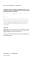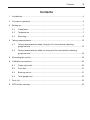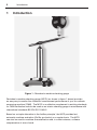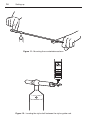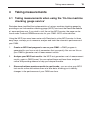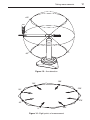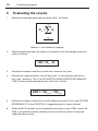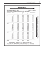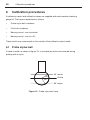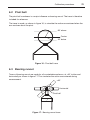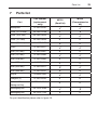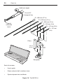
1
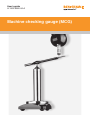
User’s guide
H-1000-5080-04-A
Machine checking gauge (MCG)
© 2002 - 2007 Renishaw plc. All rights reserved.
This document may not be copied or reproduced in whole or in part, or
transferred to any other media or language, by any means, without the
prior written permission of Renishaw.
The publication of material within this document does not imply
freedom from the patent rights of Renishaw plc.
Disclaimer
Considerable effort has been made to ensure that the contents of
this document are free from inaccuracies and omissions. However,
Renishaw makes no warranties with respect to the contents of this
document and specifically disclaims any implied warranties. Renishaw
reserves the right to make changes to this document and to the
product described herein without obligation to notify any person of
such changes.
Trademarks
RENISHAW® and the probe emblem used in the RENISHAW logo are
registered trademarks of Renishaw plc in the UK and other countries.
apply innovation is a trademark of Renishaw plc.
All other brand names and product names used in this document are
trade names, service marks, trademarks, or registered trademarks of
their respective owners.
Renishaw part no: H-1000-5080-04-A
Issued: 04 2007
1
MCG
machine checking gauge
user’s guide
2
Care of equipment
Care of equipment
Renishaw probes and associated systems are precision tools used for obtaining precise
measurements and must therefore be treated with care.
The Renishaw recommended recalibration period for MCG is 12 months.
Recalibration periods are purely a recommendation, under normal service conditions.
However, there are several factors that may generate the need for more or less frequent
recalibrations including:•
Environmental conditions
•
Frequency and duration of use
•
Harsh treatment of the MCG system, during storage, transportation or use
•
Level of accuracy required by the user
•
The requirements of company QA procedures an / or national / local regulations
Ultimately it is for the user to determine the appropriate calibration period given his
operational environment and performance requirements.
Changes to Renishaw products
Renishaw plc reserves the right to improve, change or modify its hardware or software
without incurring any obligations to make changes to Renishaw equipment previously
sold.
Warranty
Renishaw plc warrants its equipment provided that it is installed exactly as defined in
associated Renishaw documentation.
Consent must be obtained from Renishaw if non-Renishaw equipment (e.g. interfaces
and/or cabling) is used or substituted. Failure to comply with this will invalidate the
Renishaw warranty.
Claims under warranty must be made from authorised services centres only, which may
be advised by the supplier or distributor.
Patents
Features of the machine checking gauge are subject to the following patents and patent
applications:
US 4777818
Contents
3
Contents
1
Introduction ................................................................................................................4
2
Principle of operation .................................................................................................5
3
Setting-up ..................................................................................................................7
4
3.1
Cleanliness .....................................................................................................7
3.2
Temperature ...................................................................................................7
3.3
Mounting .........................................................................................................8
Taking measurements ..............................................................................................15
4.1
Taking measurements when using the ‘On-line machine checking
gauge service’ ..............................................................................................15
4.2
Taking measurements when not using the ‘On-line machine checking
gauge service’ ..............................................................................................16
5
Evaluating the results...............................................................................................18
6
Calibration procedures .............................................................................................20
6.1
Probe stylus ball ...........................................................................................20
6.2
Pivot ball .......................................................................................................21
6.3
Bearing runout ..............................................................................................21
6.4
Total gauge error ..........................................................................................22
7
Parts list ...................................................................................................................23
8
MCG online services................................................................................................25
4
Introduction
1
Introduction
Figure 1 - Renishaw’s machine checking gauge
Renishaw’s machine checking gauge (MCG) (as shown in figure 1 above) provides
an easy way to monitor the volumetric measurement performance of your co-ordinate
measuring machine (CMM). The MCG is an effective complement to existing standards
for CMM verification and can be used as an interim checking gauge in accordance with
international standards BS EN ISO 10360-2.
Based on a simple alternative to the ‘ballbar principle’, the MCG provides fast,
automatic machine evaluation (Go/No go checks) on a regular basis. The MCG
can also be used for machine characterisation and, in some instances, software
compensation of errors found.
Principle of operation
2
5
Principle of operation
The counterbalanced arm, as shown in figure 2, has a kinematic seat which sits on
a precision ruby ball located on an adjustable tower. The kinematic seat allows very
accurate arm pivoting, both horizontally through 360° and vertically through ±45°
(please see note on page 10). At the end of the counterbalanced arm is a second
kinematic location which is formed by two rods, the tungsten carbide ball of the arm,
and the probe stylus ball. The arm is able to sweep a truncated spherical outline of
radius R about the kinematic pivot location.
The counterbalanced arm is balanced to provide a downforce of 2 gm at the measuring
end to allow arm movement without false triggering.
R
Figure 2 - Counterbalanced arm
Kinematic pivot
location
Principle of operation
6
The probe is moved to its required position (position A, figure 3) and then towards the
pivot position (B) where it will trigger at the kinematic location (C) and the radius is
measured.
Since the counterbalanced arm is of a constant radius R, any deviation from R is an
indication of the volumetric measuring performance of the CMM for that volume swept
by the arm. Repetition of a sequence of readings checks the system for repeatability.
Volumetric measuring performance is the maximum error between any two points in
any plane, over any distance within the full measuring volume.
On horizontal arm machines the probe is mounted at 90° to the arm.
A
Move to position
B
Move towards pivot
C
Trigger at kinematic location
Figure 3 - Measuring sequence
Setting-up
3
7
Setting-up
Several precautions must be taken when using the machine checking gauge (MCG).
3.1 Cleanliness
The pivot ball, probe stylus and arm forks must be scrupulously cleaned before
assembly as even a fingerprint can give an error of 3 microns. Use a proprietary
cleaner to clean the surfaces of these components.
3.2 Temperature
The components of the MCG are subject to distortion due to changes in temperature. It
is therefore important that handling of the components is kept to a minimum and that, if
handled, a five-minute temperature stabilisation period is observed once any handling
is complete. It is also recommended that the MCG is left in the vicinity of the CMM prior
to performing any checking.
8
Setting-up
3.3 Mounting
For optimum performance, it is recommended that the MCG is clamped by its base to
the table of the CMM prior to use. The recommended procedure is as follows:
NOTE: The MCG is not suitable for use with TP7M, SP600 or SP80 probes, and not
recommended for use with TP200 probes. SP25M requires a TM25-20 and TP20
module.
1.
Attach the special, calibrated stylus of the MCG (this can be readily identified
by the two grooves cut within the stylus stem) to your touch-trigger probe. If
necessary, use the extensions and adaptors supplied to allow the calibrated stylus
to be fitted to the probe (see figure 4).
TP1(S)
TP20
TP6
SE3
Stylus
SE2
SE7
Stylus
SE3
Stylus
Figure 4 - Adaptors and extensions
Setting-up
9
2.
Visually inspect the stylus ball of the calibrated stylus for contamination and clean
if required.
3.
Inspect the probe head to ensure that it is securely located in the machine quill.
4.
Construct a tower using the base, pillars and pivot. When building the tower,
ensure that the pivot ball height will be approximately half the height of the
component to be measured. If the component is mounted on a fixture, take any
added height into account (see figure 5). Tighten the pillars by hand.
Component
Fixture
Figure 5 - Building a tower
Setting-up
10
5.
Towers of varying heights are possible by using the pillars in combinations as
required (see figure 6).
Pivot
235
mm
127
mm
76.2
mm
31.75
mm
Base
Figure 6 - Available pillar extensions
Setting-up
NOTE: It is recommended that when mounting the tower to the CMM table that the
base of the tower is clamped on the central steel clamping ring.
6.
Ensuring that base of the tower is approximately central to the component
volume, position the tower on the table of your CMM (see figure 7).
Component
Figure 7 - Positioning the tower
7.
Ensure that the ball of the kinematic pivot location is perfectly clean.
8.
Allow the assembly to thermally stabilise for 2 minutes.
9.
Datum the ball of the kinematic pivot location using a minimum of (10) ten
readings (see figure 8). Set the centre of the pivot ball to be the origin (i.e. X=0,
Y=0, Z=0).
Figure 8 - Datuming the ball of the kinematic pivot location
11
12
10.
Setting-up
Select an arm radius R to suit the component. Use the following table to choose
the correct arm for your component (see figures 9 and 10).
Arm
11.
Radius
X maximum
Z maximum
mm
inches
mm
inches
mm
inches
1
101
4
143
5.6
143
5.6
2
151
6
213
8.4
213
8.4
3
226
9
320
12.7
320
12.7
4
380
15
537
21.2
537
21.2
5
532
21
752
29.6
752
29.6
6
685
27
986
38.1
986
38.1
Visually inspect the chosen counterbalanced arm for cleanliness. Make sure
that the stylus guide rods and ball of the measuring location and the three ball
pivot location are perfectly clean. If necessary, clean the parts with a suitable
proprietary cleaner.
685 mm
532 mm
380 mm
226 mm
151 mm
101 mm
Figure 9 - Arm length selections
Setting-up
X max
Component
Z max
Fixture
Figure 10 - Angle of rotation
NOTE: When position the counterbalanced arm on the pivot ball, it is important to
ensure that handling of the arm is kept to an absolute minimum to avoid thermal
distortion occurring.
12.
Locate the counterbalanced arm on the pivot ball as shown in figure 11.
13.
Locate the stylus ball between the stylus guide rods as shown in figure 12.
14.
Allow the assembly to thermally stabilise for a minimum period of 5 minutes.
3.3.1 Additional weights
Each counterbalanced arm is set to provide a downforce on the stylus ball which is
sufficient to allow the probe and the arm to be moved without causing false triggers.
If required, the downforce may be increased by attaching additional weights to the
counterbalanced arm to allow greater speeds and/or acceleration to be used.
13
14
Setting-up
Figure 11 - Mounting the counterbalanced arm
Figure 12 - Locating the stylus ball between the stylus guide rods
Taking measurements
4
15
Taking measurements
4.1 Taking measurements when using the ‘On-line machine
checking gauge service’
Renishaw have simplified the implementation of using a machine checking gauge by
providing an on-line machine checking gauge (MCG) service at the Renishaw website
at www.renishaw.com. If you wish to visit the on-line MCG service, the page can be
found under Products/CMM/Accessories for your CMM - MCG online services.
Using the MCG has never been easier with Renishaw’s online MCG service. In three
easy steps, we help you to measure, analyse and track the volumetric performance of
your CMM:
1.
Create an MCG test program to run on your CMM - a DMIS program is
generated for you from a set of parameters that you specify. You can run this on
your CMM to generate a set of measurement results.
2.
Analyse your MCG test results - the MCG test generates a set of measurement
results, again in DMIS format. You can upload these and have them analysed
online. We provide guidance to help you interpret the data.
3.
Store and retrieve previous results to spot trends - you can store your MCG
test results online and retrieve them at a later date, allowing you to identify
changes in the performance of your CMM over time.
16
Taking measurements
4.2 Taking measurements when not using the ‘On-line
machine checking gauge service’
1.
Arm elevation 0° - measure the arm radius R at 45° intervals in the horizontal
plane (a total of eight measurements) as shown in figures 13 and 14.
2.
Arm elevation -45° - measure the arm radius R at 45° intervals in the horizontal
plane (a total of eight measurements) as shown in figures 13 and 14.
3.
Arm elevation +45° - measure the arm radius R at 45° intervals in the horizontal
plane (a total of eight measurements) as shown in figures 13 and 14.
4.
Repeat steps 1 to 3 twice to obtain repeatability measurements. This provides
a total of 72 (3 × 24) measurements for evaluation of volumetric measuring
performance and system repeatability.
5.
Remove the counterbalanced arm carefully and re-datum the pivot ball using a
minimum of ten readings (refer to ‘Setting -up’, step 9). If the pivot ball centre has
moved significantly more than the maximum measured repeatability, re-datum the
pivot ball ensuring that:
a. The seating faces between the pivot , pillars and baseplates are perfectly
clean and that these parts are firmly tightened.
b. The stated pillar thermal stabilising period (2 minutes minimum) is observed.
c. The utmost care is taken when placing the counterbalanced arm of the pivot.
Taking measurements
17
+45°
0°
-45°
Figure 13 - Arm elevation
180°
135°
225°
90°
270°
45°
0°
325°
Figure 14 - Eight points of measurement
18
5
1.
Evaluating the results
Evaluating the results
Evaluate the average measured arm radius, RAV as follows:
Σ
i=n
RAV =
Ri
i=1
n
Where n = total number of readings
2.
Evaluate each measured arm radius for its deviation from the average measured
radius as follows:
∆R = R
i
AV
- Ri
3.
Evaluate the range of deviation for each run, known as the ‘span’.
4.
Evaluate the range deviations over all three runs, i.e. the maximum deviation in
the + and - directions. This is the VOLUMETRIC MEASURING PERFORMANCE
(VMP) for the volume swept by the arm radius R as follows:
VMP =
∆R
i(max)
-
∆R
i(min)
5.
Evaluate the range of deviations for each measuring position. This is the SYSTEM
REPEATABILITY at that POSITION. A suggested layout is shown overleaf.
6.
When the MCG indicates an unacceptable performance of your CMM, contact the
OEM to service the machine (please note that this service cannot normally be
undertaken by the user).
Evaluating the results
19
20
6
Calibration procedures
Calibration procedures
A calibration report and calibration traces are supplied with each machine checking
gauge kit. The traces supplied are as follows:
•
Probe stylus ball roundness
•
Pivot ball roundness
•
Bearing runout - arm horizontal
•
Bearing runout - arm at +45°.
These results are summarised on the outside of the calibration report wallet.
6.1 Probe stylus ball
A trace is made, as shown in figure 15, to simulate the action encountered during
probing with a stylus.
30° above
30°
Centre
60°
60° below
Figure 15 - Probe stylus ball trace
Calibration procedures
21
6.2 Pivot ball
The pivot ball roundness is a major influence on bearing runout. The trace is therefore
included for reference.
The trace is made, as shown in figure 16, to simulate the action encountered when the
arm revolves about the pivot.
60° above
Centre
30° below
Figure 16 - Pivot ball trace
6.3 Bearing runout
Traces of bearing runout are made for all counterbalanced arms, at +45° incline and
horizontally as shown in figure 17. This simulates the action encountered during
measurement.
+45°
Horizontal
Pivot ball
Figure 17 - Bearing runout trace
22
Calibration procedures
6.4 Total gauge error
The total gauge error comprises the following components:
Plus
Stylus ball roundness
0.25 µm maximum
Bearing runout
0.25 µm maximum
Total gauge error
0.50 µm maximum
Parts list
7
23
Parts list
Part
Part number
(replacement
only)
Baseplate
A-1007-0016
Pillar (31.75 mm)
M-1007-0158
Pillar (76.2 mm)
M-1007-0023
Pillar (127 mm)
M-1007-0024
Pillar (235 mm)
M-1007-0025
Pivot
A-1007-0017
Arm (101 mm)
A-1007-0007
Arm (151 mm)
A-1007-0008
Arm (226 mm)
A-1007-0009
Arm (380 mm)
A-1007-0010
Arm (532 mm)
A-1007-0011
Arm (685 mm)
A-1007-0012
Stylus
A-5000-7650
Weights (2)
A-1007-0018
1.5 mm AF
hexagonal key
P-TL01-0150
Mahogany box
M-1015-7646
Mahogany box
M-1015-7704
For part identification please refer to figure 18.
MCG1
(Small kit)
MCG2
(Comprehensive
kit)
✓
✓
✓
✓
✗
✓
✓
✓
✓
✓
✗
✗
✓
✓
✓
✓
✗
✓
✓
✓
✓
✓
✓
✓
✓
✓
✓
✓
✓
✓
✓
✗
✗
✓
24
Parts list
Additional weight
1.5 mm A/F
hexagonal key
R = 685 mm (27 in)
R = 532 mm (21 in)
R = 380 mm (15 in)
Special
calibrated
stylus
R = 226 mm (9 in)
R = 151 mm (6 in)
R = 101 mm
(4 in)
Pivot
Pillars
235 mm
(9.25 in)
127 mm
(5 in)
31.75 mm
(1.25 in)
72 mm
(3 in)
Baseplate
Each kit includes:
•
User’s guide
•
Stylus and pivot ball roundness trace
•
System dynamic test certificate
Figure 18 - The MCG2 kit
MCG online services
8
25
MCG online services
It is possible to create an MCG (machine checking gauge) test program online to run on
your CMM and analyse the results.
NOTE: This service is only available from the Renishaw website www.renishaw.com.
This section explains both the online MCG service and the actual MCG test.
Renishaw’s online MCG service provides an easy way to monitor the volumetric
measurement performance of your CMM. The unique MCG system enables calibration
traceable to USA National Institute of Standards and Technology (Ref #731/23897-87)
and British Standard BS EN ISO 10360-2.
8.1 The MCG test
The probe stylus slots into the end of what is in effect a reference “ball” bar. The probe
carries the bar with it over a spherical path, and radial readings are taken at different
positions. The range of these readings indicates the volumetric measuring performance
of the CMM. Repetition of a sequence of readings checks the system for repeatability.
Volumetric measuring performance is the maximum error between any two points in
any plane, over any distance within the full measuring volume.
A special calibrated stylus can be used with TP1, TP2, TP20, TP6 and TP6A, with
suitable adaptors.
8.2 The online MCG service
Using the MCG has never been easier with Renishaw’s online MCG service. In three
easy steps, you can measure, analyse and track the volumetric performance of your
CMM:
1.
Create an MCG test program to run on your CMM - a DMIS program is
generated for you from a set of parameters that you specify. You can run this on
your CMM to generate a set of measurement results.
2.
Analyse your MCG test results - the MCG test generates a set of measurement
results, again in DMIS format. You can upload these and have them analysed
online. We provide guidance to help you to interpret the data.
3.
Store and retrieve previous results to spot trends - you can store your MCG
test results online and retrieve them at a later date, allowing you to identify
changes in the performance of your CMM over time.
Renishaw plc
New Mills, Wotton-under-Edge,
Gloucestershire, GL12 8JR
United Kingdom
T
F
E
+44 (0)1453 524524
+44 (0)1453 524901
[email protected]
www.renishaw.com
For worldwide contact details,
please visit our main website at
www.renishaw.com/contact
*H-1000-5080-04*