1
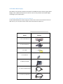
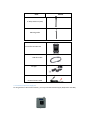
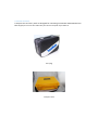
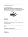
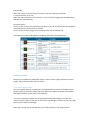
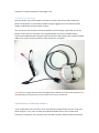
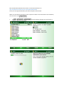
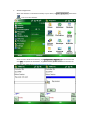
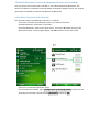
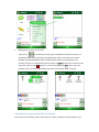
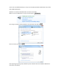
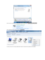
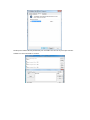
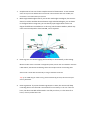
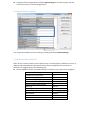
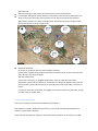
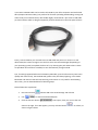
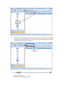
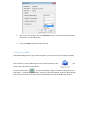
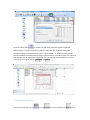
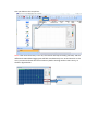
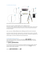
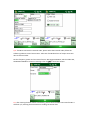
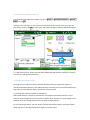
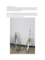
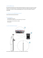
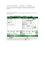
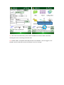
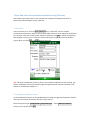
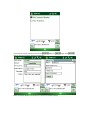
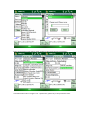
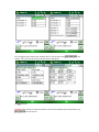
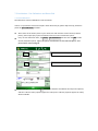
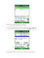
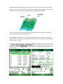
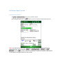
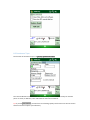
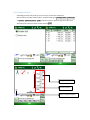
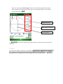
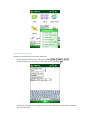
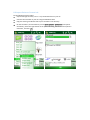
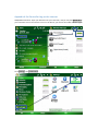
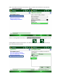
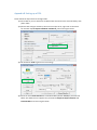
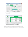
USER GUIDE SUNNAV S100 Version 1.1 2014.07.15 Copyright Copyright 2014 SunNav. © 2013 SunNav Tech Ltd. All rights reserved. The SunNav is trademark of Tianjin sunnav technology Limited. All other trademarks are the property of their respective owners. Trademarks All product and brand names mentioned in this publication are trademarks of their respective holders. FCC Notice SunNav S100 receivers comply with the limits for a Class B digital device, pursuant to the Part 15 of the FCC rules when it is used in the Portable Mode. Operation is subject to the following two conditions: (1) This device may not cause harmful interference and (2) this device must accept any interference received, including interference that may cause undesired operation. Where to Find Information This manual is designed to guide you through the basic S100 procedures and operations. CONTENT 1 Introduction ................................................................................................................................... 4 1.1 Technical Assistance ............................................................................................................ 4 1.2 Your Comments ................................................................................................................... 4 1.3 Safety Information............................................................................................................... 4 1.3.1 Regulations and Safety ............................................................................................. 4 1.3.2 Use and Care ............................................................................................................ 4 2 General Information ....................................................................................................................... 5 2.1 Overview ............................................................................................................................. 5 2.2 Technical Specifications ....................................................................................................... 5 2.3 Product Basic Supply ........................................................................................................... 8 2.3.1 SunNav S100 GNSS Receiver Basic Supply Kit......................................................... 8 2.3.2 Datalink Optional Supply Kit .................................................................................... 9 2.3.3 Case and Pack ......................................................................................................... 10 3 Products View .............................................................................................................................. 11 3.1 Parts of The Receiver ......................................................................................................... 11 3.1.1 Front Panel ............................................................................................................. 11 3.1.2 Lower Housing........................................................................................................ 11 3.2 Batteries ............................................................................................................................ 11 3.2.1 Battery Safety ......................................................................................................... 11 3.2.2 Charging the Lithium-ion Battery ........................................................................... 12 3.2.3 Battery Charger ...................................................................................................... 12 3.2.4 Storing of the Lithium-ion Battery.......................................................................... 12 3.2.5 Disposing of the Battery ......................................................................................... 13 3.3 Button and LED Operations ............................................................................................... 13 3.4 Power Supply..................................................................................................................... 14 3.4.1 Internal Power Supply ............................................................................................ 14 3.4.2 External Power Supply ........................................................................................... 15 3.5 Installation of CGSurvey Software ..................................................................................... 15 4 Establish Bluetooth Connection Between Receiver and Controller ............................................. 18 4.1 Establish Connection with Controller ................................................................................ 18 4.2 Establish Connection with Office Computer ..................................................................... 19 5 Static Mode .................................................................................................................................. 23 5.1 Static Mode Configuration ................................................................................................ 23 5.2 Default Receiver Settings .................................................................................................. 25 5.3 Field Static Data Collection ............................................................................................... 25 5.4 Raw Data Download .......................................................................................................... 26 5.4 Convert to RINEX ............................................................................................................... 29 5.5 Memory Management ...................................................................................................... 30 6 Real-Time Kinematic Mode .......................................................................................................... 32 6.1 Radio Mode ....................................................................................................................... 32 6.1.1 S100 Internal Radio Specifications ......................................................................... 32 6.1.2 Prerequisites........................................................................................................... 32 6.1.3 Radio Mode Setting-Up .......................................................................................... 33 6.1.4 Start Base Station by CGSurvey .............................................................................. 33 6.1.4 Start Rover Station by CGSurvey ............................................................................ 35 6.1.5 Radio Signal Enhancement ..................................................................................... 35 6.2 PDA CORS Mode ................................................................................................................ 37 6.2.1 R100 Controller GSM/GPRS Specifications............................................................. 37 6.2.2 Prerequisites: ......................................................................................................... 37 6.2.3 PDA CORS Mode Setting-Up ................................................................................... 37 6.2.4 Start Rover by CGSurvey......................................................................................... 38 7 Start New Job and Coordinate Localization using CGSurvey ........................................................ 40 7.1 New Job ............................................................................................................................. 40 7.2 Creating Coordinate System .............................................................................................. 40 7.3 localization-- Site Calibration and Reset Grid .................................................................... 44 7.3.1 Site Calibration ....................................................................................................... 44 7.3.2 Reset Grid Function ................................................................................................ 45 8 CGSurvey Basic Function .............................................................................................................. 47 8.1 Measuring Points ............................................................................................................... 47 8.2 Continuous Topo ............................................................................................................... 48 8.3 Staking out Points .............................................................................................................. 49 8.4 Cogo .................................................................................................................................. 50 8.5 Export Points to PC ............................................................................................................ 51 8.6 Import Points to Current Job ............................................................................................. 52 Appendix A Set Controller Log on the Internet ............................................................................... 53 1 Introduction Thank you for choosing SunNav S100 GNSS Receiver. This manual is designed to help you to rapidly familiarize with S100, and start your project with S100. 1.1 Technical Assistance If you have any question and cannot find the information you need in the documentation, contact your local Dealer. Alternatively, please request technical support using the SunNav Website at(http://www.sunnavtech.com/) or S100 receiver technical support email [email protected]. 1.2 Your Comments Your feedback about the supporting documentation will help us to improve the products. Please e-mail your comments to [email protected]. 1.3 Safety Information This manual describes SunNav S100 GNSS Receiver. Before you use S100, please make sure that you have read and understood this publication, as well as safety requirements. 1.3.1 Regulations and Safety The receiver contains integral Bluetooth® wireless technology and UHF. Regulations regarding the use of the datalink vary greatly from country to country. In some countries, the unit can be used without obtaining an end-user license. But in some countries the administrative permissions are required. For license information, please consult your local dealer. Bluetooth® operates in license-free bands. 1.3.2 Use and Care The receiver can withstand the rough treatment that typically occurs in the field. However, the receiver is high-precision electronic equipment and should be treated with reasonable care. 2 General Information 2.1 Overview The SunNav S100 GNSS Receiver provides the following features: Ultra small and super light - Size (W × H): 15.8cm × 7.5cm - Weight: 0.95kg (including 2 batteries) 256 channels with simultaneously tracked satellite signals - GPS: L1 C/A, L1/L2 P, L5 - BeiDou: B1, B2, B3 - GLONASS: L1/L2 - SBAS: WASS, EGNOS, MASAS Increased measurement traceability with SunNav’s unique QUAN™ algorithm technology Many user-friendly conveniences built in Hot swap battery design: low power consumption with hot swap battery design, when the warning sounds and LED flashes, put your second battery in place Bluetooth wireless technology for cable free Simple keypad with on/off buttons and LED indicators for power, radio, Bluetooth, and satellite tracking IP67,Absolutely waterproof Full base/rover interoperability Operates within a VRS™ network for conventional base station-free rover capability Integrated receive and transmit radio Support long baseline E-RTK™, namely Beidou B3 signal used in RTK calculate engine; concern the current situation, this mode can be used in south east Asia 2.2 Technical Specifications Signal Tracking 256 channels with simultaneously tracked satellite signals - GPS: L1 C/A, L1/L2 P, L5 - BeiDou: B1, B2, B3 - GLONASS: L1/L2 - SBAS: WASS, EGNOS, MASAS Performance Specifications Cold start: < 50s Warm start: < 30s Initialization time: typically < 10s Initialization reliability: typically > 99.9% Signal reacquisition: < 2s Positioning Specifications Post Processing Static - Horizontal: 2.5mm + 1ppm RMS - Vertical: 5mm + 1ppm RMS Real Time Kinematic (RTK) - Horizontal: 10mm + 0.5ppm RMS - Vertical: 20mm + 0.5ppm RMS E-RTK(< 100km) - Horizontal: 0.2m + 1ppm RMS - Vertical: 0.4m + 1ppm RMS Code differential GNSS positioning - Horizontal: .0.25m + 1ppm RMS - Vertical: 0.5mm + 1ppm RMS SBAS: Typically < 1m 3D RMS Standalone: < 1.5m RMS Communications 1 Serial port(7 Pin Lemo), Baud rates up to 921600 bps Radio modem: Tx/RX with full frequency range from 410-470 Mhz - Transmit power: 0.5-2W adjustable - Range: 1-4km Position data out rates: 1Hz, 2Hz, 5Hz, 10Hz 5 LED Indicating light (indicating Power, Satellite Tracking, Differential Data an Data Recording) Bluetooth: V 2.X protocol, compatible with windows 7, Windows Mobile and Android Data Format Data inputs/outputs - Correction data I/O: RTCM 2.x, 3.x, CMR (GPS only), CMR+ (GPS only) Position data outputs - ASCII: NMEA-0183 GSV, RMC, HDT, VHD, GGA, GSA, ZDA, VTG, GST, PJK, PTNL - SunNav Binary update to 20Hz Physical Size (W×H): 15.8cm×7.5cm Weight: 0.95kg (include 2 batteries) Environmental Operating temperature: -40℃ to +65℃ Storage temperature: -40℃ to +85℃ Humidity: 100% condensation Waterproof and dust proof: IP67 protected from temporary immersion to depth of 1 meter, floats Shock: survives a 2 meter drop on to concrete Electrical Input Voltage: 5-27 VDC Power consumption: 2.85 W(3 constellations) Li-ion battery capacity: 2×1800 mAh, up to 8 hours typically Memory: 256 MB internal memory and 100MB for static data record Software (optional) SunNav CGSurvey field software SunNav Compass Receiver Utility Office software (CRU) SurvCE or Field Genius( ready ) 2.3 Product Basic Supply The tables in this section provide an overview of the different items of basic supply. Basic Supply is the standard accessories for each kit. We can also provide customized supply according to your requirement. 2.3.1 SunNav S100 GNSS Receiver Basic Supply Kit SunNav S100 GNSS Receiver Basic Supply Kit contains two receivers and related accessories. With this kit, you can perform basic radio mode as described in chapter 6.1. Items Picture 2* Kits S 100 Receiver 4* Lithium Battery H.I. Tape 2* Connector 2* Battery Charger 2* Lemo to RS232 Cable 2* Lemo to USB Cable 2 Item Picture 2* Whip Antenna (UHF) 2M Range Pole Controller PDA IGS-150 USB data cable Chrager External Power Cable 2.3.2 Datalink Optional Supply Kit For long distance radio communication, you may need this Datalink Supply Kit(SunNav UDL-300) 2.3.3 Case and Pack Transport Case and Carry Pack are designed for containing one SunNav S100 GNSS Receiver Basic Supply Kit. You can also order two pairs of case and pack if you’d like to. Carry bag Transport case 3 Products View 3.1 Parts of The Receiver All buttons and LEDs are located on the front panel. Serial port and connectors are located on the bottom of the unit. 3.1.1 Front Panel The Power button function is power on and power off the receiver. The Function button is to enable or disable the raw data recording. The indicator LEDs show the status of data logging/downloading, power, satellite tracking, Bluetooth, and radio transmit/receive. 3.1.2 Lower Housing The lower housing contains a communication/power port, radio antenna connector, two batteries and a fixing screw in the center. 3.2 Batteries The receiver has two rechargeable Lithium-ion batteries, which can be removed for charging. During surveying, the internal batteries typically provide about 8 hours of power for a rover operation. About 4.5 hours if it is operated as a base station using the internal 460-470 MHz Tx (transmit at 0.5watt) radio. These times vary according to different operations and conditions. In RTK mode, if the base station uses internal UHF to transmit correction data, which will enable the power consumption a lot, we strongly suggest to use external power supply for base station receiver. Refer to chapter 3.4.2 for details about external power supply. 3.2.1 Battery Safety Charge and use the battery only in strict accordance with the instructions provided. WARNING – Do not damage the rechargeable Lithium-ion battery. A damaged battery can cause an explosion or fire, and can result in personal injury and/or property damage. To prevent injury or damage: – Do not use or charge the battery if it appears to be damaged. Signs of damage include, but are not limited to, discoloration, warping, and leaking battery fluid. – Do not expose the battery to fire, high temperature, or direct sunlight. – Do not immerse the battery in water. – Do not use or store the battery inside a vehicle during hot weather. – Do not drop or puncture the battery. – Do not open the battery or short-circuit its contacts. WARNING – Avoid contact with the rechargeable Lithium-ion battery if it appears to be leaking. Battery fluid is corrosive, and contact with it can result in personal injury and/or property damage. To prevent injury or damage: – Do not use or charge the battery if it appears to be damaged. Signs of damage include, but are not limited to, discoloration, warping, and leaking battery fluid. – Do not expose the battery to fire, high temperature, or direct sunlight. – Do not immerse the battery in water. – Do not use or store the battery inside a vehicle during hot weather. – Do not drop or puncture the battery. – Do not open the battery or short-circuit its contacts. 3.2.2 Charging the Lithium-ion Battery The rechargeable Lithium-ion battery is supplied partially charged. Charge the battery completely before using it for the first time. Charging takes approximately 3.5 hours per battery at room temperature. If the battery has been stored for a long time, charge it before your field work. To charge the battery, first remove the battery from the receiver, and then place it in the battery charger, which is connected to AC power. 3.2.3 Battery Charger The charger has two slots and can charge two Lithium-ion batteries simultaneously, beside each slot there is a LED indicator to display the charging status. Refer to the table below for detailed information. Indicator status Battery status Blue Red Blue No battery in Charging Fully charged 3.2.4 Storing of the Lithium-ion Battery Do not keep batteries inside the receiver if the receiver not used for long time, take out the batteries from receiver for shipment. 3.2.5 Disposing of the Battery Discharge a Lithium-ion battery before disposing of it. Dispose of batteries is an environmentally sensitive manner, and adhere to any local and national regulations concerning battery disposing or recycling. 3.3 Button and LED Operations The LEDs on the front panel indicate receiver working status. Generally, a lit or slowly flashing indicates normal operation, and an unlit LED indicates that no operation is occurring. On the front panel, the LEDs stand for power, radio, satellite, Bluetooth, Data logging/downloading respectively. The following items define each possible LED state: (1) Differential LED: As a Base station: the differential LED flashes once per second when sending out differential data in RTK mode. As a Rover station: the differential LED flashes when getting differential data from Base station or Network. Flashing intervals indicate the delay of differential data. (2) Satellite LED: The LED indicator shows the number of satellites that receiver is tracking on, e.g. the LED flashing N times continuously means the receiver is tracking N satellites; once means the receiver is searching satellites. (3) Bluetooth LED: The LED indicator flashes when controller or PC is connected with the S100 receiver via Bluetooth. (4) Battery LED: The indicator shows S100 GNSS receiver is on or off. All the two battery LEDs will be on if you use the external power supply and only one is on if you use the internal batteries. The buzzer will alarm if the power is going to be run out. (5) Data logging: The data logging button only flashes under the following situations: A. In the static mode The interval of flashing shows the sample interval of collecting data. B. RTK mode When the receiver is connecting to Controller or PC and receiving commands. C. Internal memory is run out When the internal memory of the receiver is run out, the data logging LED and differential LED flash 1/s simultaneously. (6) Power button: To turn on the receiver, press the button for about 1 second, all the five LEDs above light up simultaneously and remain lit for 3 seconds. To turn off the receiver, long press the power button until all the LEDs off. The states of the LEDs under different conditions are listed in the table below: 3.4 Power Supply We have two methods for S100 power supply: internal power supply and external power supply. They will be introduced in this section. 3.4.1 Internal Power Supply Two rechargeable Lithium-ion batteries are supplied with the receiver. The S100 receiver adopts the hot swap battery design which can effectively reduce the power consumption and make the whole system work more efficiently. If you put one battery in S100, the corresponding battery LED will light; if you put two, receiver will use battery A first and the left battery LED will light; if battery A is run out, right battery LED for battery B will light. When the warning sounds and LEDs flash, put another battery in the empty battery container or replace the battery whose light is off. 3.4.2 External Power Supply The base station uses internal UHF to transmit correction data, which will increase the power consumption a lot, therefore, SunNav strongly suggest you to use external power supply (7-28 volt DC) for base station receiver. You can connect the receiver to an external power source through 7-pin Lemo port in the bottom of the receiver. As shown in the snapshot below, use Lemo to RS232 cable to connect with S100 and external power cable. Connect the red alligator clips of external power cable to the positive of external battery and the black one to negative. Tips: Please use 7-28V external battery with high quality. S100 have the protection mechanism of reversed battery connection, but it cannot work if you reverse connection. 3.5 Installation of CGSurvey Software If you use Windows 8 OS, Controller can be automatically recognized when you link it with your office computer. If not, make sure Microsoft Windows Mobile Device Center or Microsoft ActiveSync is installed on your computer and is allowed to perform USB connections (download Microsoft Windows Mobile Device Center or Microsoft ActiveSync via http://windows.microsoft.com/en-us/windows/downloads). Then, you can copy files between your office computer and controller. Make sure the software package has been copied in a folder of controller before the installation; here we save it in the Program Files. Tap Start->File Explorer->Program Files, find the software package, tap it and choose a location to start the installation. Software Registration When the software is installed successfully in your device, tap Start->Programs and find the icon to run the software. Go to the main window of CGSurvey, tap Configuration->Register, enter the license and click OK to complete the installation. To get the license, please email with Controller SN found in your CGSurvey to [email protected] 4 Establish Bluetooth Connection Between Receiver and Controller You can connect the receiver with controller or your office computer by Bluetooth. The CGSurvey software is installed in Controller based on Windows® Mobile system. This chapter shows how to establish connection with Receiver by Bluetooth. 4.1 Establish Connection with Controller The operation steps of establishing connection is as follows: Turn on the controller and the GNSS receivers you want to work with. Activate Bluetooth® connection of controller. Check the Bluetooth® status on the start screen. Turn on the Bluetooth by tap on the Bluetooth® button, shown as figure below. Tap OK and return to the start screen. Select the corresponding Bluetooth name Run the CGSurvey software, tap on Configuration->Com Configuration to come into the Controller port window, choose the term Bluetooth and then tap OK. Binding your receiver to controller Tap the icon, the PAD starts searching for the Bluetooth® devices nearby. For each device detected by Controller, the Bluetooth® name is returned in the search window (e.g.S100-03101034). Select the Bluetooth® name corresponding to the receiver you want to communicate with and then tap Bond to bind your receiver to the controller. Then an icon appears on the receiver icon. Tap Ok to go to the main window. So far, you have successfully connected your receiver with controller. 4.2 Establish Connection with Office Computer There are 3 ports of S100, com1 is the Lemo port, com2 is linked to internal datalink, and com3 is the virtual Bluetooth port. So you can use PDA (windows mobile OS) or PC to link with S100 by Bluetooth. Windows 7 or XP OS PC built Bluetooth connection with S100 Make sure your PC Bluetooth is on, go to control panel -> Add device This will go to the BT searching window, select the Device ID and click Next. Enter the device pairing code 0000 After inputting the pairing code, Windows system indicates that PC and S100 link Bluetooth connection successfully. Next to check the Bluetooth connection port, go to control panel-> View device and printers Select S100 SN number, right click and click Properties In service, com12 is virtual port Bluetooth used for communication between PC and S100 The BT port of S100 is directly linked with port 3 of S100. You can use any serial port monitor software to send commands to receiver. 5 Static Mode This chapter describes how to use S100 for static survey. According to the workflow of static survey, we will explain the operation in the following 5 sections--receiver configuration, default setting, static data download, convert data to Rinex format and receiver memory management. 5.1 Static Mode Configuration Use CRU (Compass receiver utility) software to configure S100. You can download the software from the below link: http://www.SunNavtech.com/download.asp?bigclassid=28 After download and install software, please follow the step to configure S100. Tips: The connection from PC to S100 must use Serial port protocol, so please make sure your computer has serial port (serial port or USB to RS232 serial port). Power on S100, use the 7 pin LEMO (link with S100 LEMO) to RS232 (link with PC) cable to build connection from receiver to PC. to choose the COM and Baud Rate (default Run the software CRU and click icon is 115200bps), and then click OK to make the receiver connect with your computer. If the connection is successful, you will see the SN No. of receiver in the left top icon of CRU software, then go to the next step. If not, check the band rate and whether the serial port is correct. Click icon to configure: 1. Sample interval: You can choose sample interval of observations. As the standard static survey use the default value 15 seconds. The maximum data rate is 20Hz, the minimum is one observation per minute. 2. Mask angle: Mask angle means if you set the mask angle to N degree, the receiver doesn’t track the satellite whose elevation angle is below N degree, just as shown in the figure below. Using CRU, you can directly input angle values such as 10 degree for different constellations. In this way, low elevation satellites, which may cause serious multipath or have low SNR, can be rejected. 3. Data Log: You can choose logging data manually or automatically in this setting. Manual mode: data is recorded or stopped by hand, hold on the record button until the radio LED off, the Record Led flashing shows the sample interval of collecting data. Auto mode: record data continuously as long as satellites received. Tips: if use S100 only for static survey, please set data log as auto, this will save your time in field work. 4. Data Log Session: If you set the Data Log Session to Auto, the receiver will keep recording data in one file until it is turned off or its memory is run out. If set to 1 hour, the data recorded will be saved in one file per 1 hour, it is the same for 2 hours, 3 hours, and 4 hours etc. Complete all the configurations and click Apply Settings to save the settings. Exit and restart the receiver to active configurations. 5.2 Default Receiver Settings You can get these default receiver settings by clicking the button Default Settings. 5.3 Field Static Data Collection Static survey is mainly used for control point survey. As control points, millimeter accuracy is required. The standard and requirement of static survey is different from countries to countries, we suggest doing in the following way: At least 3 GNSS receivers are needed, because 3 receivers can construct the triangular Settings Sample Interval (second) GPS Mask Angle (degree) BDS Mask Angle (degree) GLONASS Mask Angle (degree) GALILEO Mask Angle (degree) Data Log Data Log Session Port Configuration Work Mode Correction Port Format of Correction Factory default 15 15 15 15 15 Manual Manual Normal Normal Port1 CMR and stable net. Make plan and go to the project to make the point mark on the ground. For example, 1&2 points are the primary control points, they are the known points, we want to survey the secondary control points A1, A2, A3, A4 and A5; firstly mark the approximate position of 1 and 2 in Google Earth, then based on project request make the mark of points A1-A5 in Google Earth. A1 ? A2 ? ❶ A4? A3? A5? ❷ Field data collection. Go to the A1-A5 points and start the field data collection. Each section of observation please write down the station name, receiver SN, start time and end time, also antenna height. The data collect flow. If you have 3 receivers, we suggest fixing them in 1,A1,A3, after the first section observation, power off the receiver on 1 and take it to the points A5(A2 or A4); after the second section, power off the receiver on A1 and move to A4; finally take 1 receiver on point 2. If you have more than 3 receivers, we suggest you fix two receivers on point 1&2, and go to other points to collect data. 5.4 Raw Data Download This section explains how to download data by CRU software. The raw data is saved in S100 internal memory. So you need to download the data from receiver to your office computer. There could be two types of cables can be used to export raw data in the memory of S100. 7-pin Lemo to RS232 cable can be used to link S100 to your office computer and with which CRU (Compass Receiver Utility) can perform full function (including downloading, setting and other serial port communication). But SunNav highly recommends 7-pin Lemo to USB cable (as shown below) which is designed especially for data download so that the speed is faster. Firstly, connect S100 to your PC with Lemo to USB cable and power on receiver. PC will detect S100, but cannot recognize it at the first time. Use Device Manager (depending on your operating system) to update the drive of it, by choosing the path where there is drive we provided. Once the drive installed, PC can automatically recognize S100. Tips, if nothing happened when PC link S100 by USB cable, press the function key two times rapidly and continuously, the DatalinK LED (yellow color) will always lighting, in this mode Bluetooth and internal radio will stop working, and receiver is only used for downloading data. Then, you can download data as following steps: Please follow the steps below 1. Run CRU and click . Choose USB in the Serial Settings and click OK. 2. Use 3. Click the function button File Download in the Project, then you can see the raw to choose the download path. data on the right. If no data appear, you may click the button shown in figure below to refresh, as 4. Choose the corresponding data, right click and then you can edit the data by means of Modify, Download and Delete. You also can use the corresponding shortcut keys in the shortcut bar, as shown in below. Choose Modify, only two important information need to modify. After that, click OK. Name: station marker Antenna: the antenna height of S100. After set the storage path, you click Download and then the data can be downloaded and saved in corresponding path. If you click Delete, the data will be removed. 5.4 Convert to RINEX After downloading data on your office computer, you can convert the raw data in SunNav binary format (*.cnb) to Rinex format. Go to the function bar, click will see the raw data in current folder. , you Go to the shortcut bar or Convert Settings in right click, define the Rinex version and export observation information. Then go to the main window, select the file and right click, convert to Rinex format. Go to the raw data files to check the RINEX format data. Go to the shortcut bar or Anttena in right click, select the Antenna Type and Measurement. If no existing antennna type for S100, add one. Input the value of R0 (horizontal offset from measurement mark to phase center, i.e., antenna radius) and h0 (horizontal offset from measurement mark to phase center). For S100 receiver, the values of R0 is 0.079m and h0 is 0.0274m respectively. You can also add, edit or delete one or more antenna types using the buttons Add, Edit and Delete. 5.5 Memory Management Go to the Shortcut Bar, go to , you can format the internal memory or Clear the files that you delete to the recycle bin. Note: If the internal memory is run out, the receiver will stop recording raw data, and the differential LED and data logging LED will flash simultaneously at 2-second interval. In this case, you need to format the internal memory before starting another static survey, as shown in figure below. 6 Real-Time Kinematic Mode To conduct RTK (Real-Time Kinematic) survey, radio mode and CORS mode can be employed. 6.1 Radio Mode Radio mode is that the correction data is transmitted via radio communication in real time. SunNav S100 GNSS Receiver is equipped with internal transmitting & receiving radio, the following will explain S100 T/x+ S100 R/x RTK operation. 6.1.1 S100 Internal Radio Specifications Radio parameter Specifications Frequency range 460 MHz-470 MHz Protocol Transmit mode: Transparent Receiving mode: MAC(compatible with CHC protocol), TT450S, Transparent and south protocol. Airlink rate 9600 bps Bandwidth 12.5kbps Power 0.5, 1, 2 Watt adjustable Work distance 3-4km, depends on environment and power setting 6.1.2 Prerequisites Two kits S100 GNSS receiver All S100 GNSS receivers can be either work as Base or Rover. Use external power source and power cable to supply power to S100 Base station (When S100 in base mode and transmitting via internal radio, the power consumption can be reached 5-6 watt, so we strongly suggest to use the external power source to supply power to base station.) Controller kit with software installed Tripod and tribrach 6.1.3 Radio Mode Setting-Up The hardware connection information of the radio mode is as follows: Base station components: ③S100 ②Extension bar ④Whip antenna Connection relation in Base part: whip antenna is connected to TNC connector; extension bar is connected to fixing socket under S100; extension bar, tribrach and tripod are connected from top to bottom. Rover components: ③S100 ④Whip Antenna ⑤Range Pole ① Controller and bracket. Connection relation in Rover part: whip antenna is connected to UHF connector under S100; range pole is connected to fixing socket under S100; controller is mounted on range pole by a bracket support; controller and S100 communicate by Bluetooth. 6.1.4 Start Base Station by CGSurvey Link controller with S100 (see chapter 4.1), Run CGSurvey, Files->New Job, Input the Job name, and in the Datum menu, edit the local coordinate system (see chapter 7.2 Creating Coordinate System ) Go to Survey -> Start base receiver To start base from known point, key in the point coordinates and antenna height, select the antenna measure type. To start base from unknown point, just tap Here, get the current position as base station coordinates. Then click Next -> Internal radio, and tap OK Tips: if S100 is connected to external radio, please select the External radio; follow the software guidance to start base station. Take care of S100 baud rate of output correction data to external radio. Set the frequency, power and correction format. We suggest RTCM3.X, which include GPS, GLONASS and Beidou correction message. Then tap OK to start base station. Tip: after starting the base station successfully, please check the differential LED of S100. It will flash 1/s, meaning the base station is sending correction data. 6.1.4 Start Rover Station by CGSurvey Link controller with S100 (see chapter 4.1), go to Survey -> Start Rover Receiver -> Internal Radio, and tap OK. It will go to the next page, set the frequency and protocol, those settings must match with the Base setting. Finally, click OK to start rover. The pattern in right screenshot below will appear, which means receiving collection data. Receiving collection data Tip: after starting rover, please also check the differential LED of S100. It will flash, meaning the rover is receiving correction data. 6.1.5 Radio Signal Enhancement By using internal radio transmission the RTK work distance may range from 3-4km. To extend the RTK work distance, two traditional ways are mainly used, fix transmit antenna on high place and use external radio to extend the transmit power. 1) Use long whip antenna instead of rod antenna Radio work distance is directly proportional to the height of transmitter antenna; in the theory 2 meters height of transmit antenna is double work distance as 1 meter height. In our experience, by use the big whip antenna can extend 1-2km distance. To use long whip antenna, you just need to connect the antenna cable to Lemo port under S100, and mount the long whip antenna highly on another tripod. 2) Use External PDL radio The Maximum transmit power of S100 is 2 Watt, in some case like mountain areas or urban, the radio signal will be easily weakened by high constructions and other powerful radio signal, then the external radio is a good solution for those cases. Here, we will introduce the settings and operations of PDL in Appendix B To set up external radio mode, link the long whip antenna mounted highly on another tripod to PDL. Then Connect S100 to PDL with Lemo cable and connect the external battery with power cable. Finally, choose appropriate channel on PDL (see chapter 6.1.4 for software operation). The cable connection of PDL is shown in the figure below. 6.2 PDA CORS Mode PDA CORS mode employs the network RTK technology with no need to set up your own base stations. The correction data is transmitted from Continuously Operating reference Station via Internet in real time. SunNav S100 GNSS Receiver can log on the Internet via WIFI or GSM/GPRS. 6.2.1 R100 Controller GSM/GPRS Specifications GSM/GPRS 850/900/1800/1900 MHz 6.2.2 Prerequisites: S100 GNSS receiver kit Controller with SIM card, set Controller log on internet Controller Kit with software installed Range pole 6.2.3 PDA CORS Mode Setting-Up The hardware connection information of the CORS mode is as follows: Hardware components: ①S100 ②Controller ③Range Pole Connection relation: range pole is connected to fixing socket under S100; controller is mounted on range pole by a bracket support; controller and S100 communicate by Bluetooth. 6.2.4 Start Rover by CGSurvey Firstly, set the controller log on internet (see Appendix A). Run CGSurvey and start a new job, edit the local datum. Then go to Survey -> Start Rover Receiver. Choose Net Diff., and then click OK. Choose Use Ntrip, key in the IP and Port of CORS, and click List to get source list. Choose one source list, key in user Name and Password, and click OK to finish setting. The icon in right screenshot below will appear, which means receiving collection data. Receiving collection data Tip: after start PDA CORS mode, please check the differential LED of S100. It will flash, meaning the rover is receiving correction data. Tip: SunNav S100 is compatible with CMR, RTCM 2.x and RTCM 3.x, but we suggest to use RTCM3.X, which include GPS, Glonass and Beidou correction message. 7 Start New Job and Coordinate Localization using CGSurvey This chapter will explain how to start new job and coordinate localization functions in CGSurvey (SunNav Geodetic Survey software). 7.1 New Job Launch CGSurvey first. Then tap Files->New job, key in Job name, select a suitable coordinate system and the right Local Time Zone which three are most important parameters for a new job. Then key in Description, Operator and Notes, click OK to accept the inputting. The program may ask you to review the relative parameters of the selected coordination system when you press OK. Press OK again to continue. Tips: about the coordination system, if there is no suitable Coordination system existing, you need to establish a new one by choosing right map projection and relative parameters, the method is introduced in chapter 7.2. 7.2 Creating Coordinate System A new coordination system can be established by choosing the right map projection method and input the relative parameters like semi-major axis etc. Choose Projection Type: Configuration->Projection Type: choose Many Projections, choose one of them and click OK. If you choose many projections, you can find Local site button in new job page. Click Local site, and you will see a page for datum management. Select the Ellipse Model in the down list or build a new Ellipse Model. Select the Projection type (UM or UTM), and key in the local Projection parameters. In transformation Tab: if using the 3 or 7 parameters, please key in the parameters here. Do not toggle the Hor.adj and Ver.adj when start a new job. After doing Site Calibration (see chapter 7.3.1), the Hor.adj and Ver.adj information will appear. Click OK to finish CAUTION: After keying in all the parameters of the local coordinate system information, tap Files->Save Job to save the Job. 7.3 localization-- Site Calibration and Reset Grid 7.3.1 Site Calibration Site Calibration: Convert WGS 84 to Local Coordinate If the 3 or 7 parameters have been keyed in when built new job, please skip this step, otherwise please do Site Calibration as follows: Select some of the known points in your work area and measure some of them (at least 3 points), then import (key in) the coordinates of them in local coordinate system. Carry out site calibration work, tap Survey->Site Calibration and then click the Add to add the Site calibration points. Input the point coordinates of the selected point, and paired with measured grid. Click here to add the inputted point Click here to add the measured point After adding all the points, click Cal button, the software will calibrate all the points inputted, and the” H.Resid “value (3 points appear this value) and “V.Resid” (4 points appear the value) will be available. CAUTION: The Max value of H.Resid has to be less than 0.015m The Max value of V.Resid has to be less than 0.02m If the Value of “H.Resid and V .Resid” meet the requirement of Max value, click OK, a pop box will appear “Do you want to replace the current datum? “, click OK, and finish the step. 7.3.2 Reset Grid Function Reset Grid option is also a unique function of CGSurvey. After doing site calibration, the relationship between WGS84 and local gird coordinate is fixed, later you start your work in different area in the some project, the base station will be moved to different places, so you need 1 point to shift your RTK coordinates between different base stations. One way is that you can start base station on known points, use this known value to shift your coordinates to match with the real value. But we suggest use “Reset Gird”, put the base station anywhere you want, survey known point by Rover and used for Reset grid, this will improve your work efficiency; the below will explain how to reset gird. Measure one point (Know point) which was measured at last setting up of base station. Then go to Files -> Element manager -> Point manager, choose the point you measure just now, and double click, you will find Reset Grid button. Click the button, choose the measured point and click the button. 8 CGSurvey Basic Function 8.1 Measuring Points Tap Survey->Measure Points, then you can measure points. After setting all parameters, tap Mea. And the point coordinates will be saved in the Job. Tips: use shortcut the Controller may improve your survey efficiency (when you measure points, use F2 instead of Mea.). Tap Configuration -> OS set, tick Use Shortcut and click OK to finish. You can use buttons F1 and F2 instead of two buttons in left bottom and right bottom of the screen. 8.2 Continuous Topo The function of continuous topo is in Survey->Continuous Topo. The same as Measure Points function but continuously. It offers 4 different ways to measure point: Fix Time, Fix Distance, Time and Distance and Time or Distance. Tip: if you tick 5Hz interval, you will find it is refreshing rapidly. This function can also be used in stake out and can improve your efficiency. 8.3 Staking out Points Uploading the stake out points to the current job, and do site calibrations. Choose stake out mode, simple mode or complex mode, go to Configuration ->stake type. Tap Survey->Stake out points-> Add to add the stake out points to the points list. Then select the point name you want to stake and tap Stake. Navigate direction Current position Stake out points (target) When the receiver gets near the target: when you reached the target position exactly, CGSurvey will make a sound to show that you are on the target position. If you want to measure this point, tap Mea. Navigate direction Stake out points (target) Current position Tip: 5Hz interval function (see chapter 8.2) can also be used in stake out and can improve your efficiency. 8.4 Cogo The function of COGO in CGSurvey is composed by Compute inverse, Compute point, Compute area, Compute azimuth, Compute rotate angle, Compute distance, Divide line and Calculator. 8.5 Export Points to PC The data can be exported out to PC after field work. Launch CGSurvey and open your Job. Then tap Files -> Export -> points, select the coordinate frame, give the new file a name and choose a file type > OK. Connect the Controller to PC using the USB cable. You can find your export result in the path: Your Controller\Files 8.6 Import Points to Current Job Do the followings issues indoor: Prepare the right format (*.txt or *.csv) coordinates files on your PC. Connect the Controller to your PC using the USB data cable. Copy the existing coordinates file to your Controller root directory. On the Controller, launch CGSurvey and tap Files->Import->Grid point (local points coordinate), select the right format of the points according, choose the file copied to Controller, and click “OK” Appendix A Set Controller Log on the Internet GSM/GPRS connection: Input your SIM card into your controller, and you may find Phone off on your controller screen. Then click it to turn on the Phone, you will see the mobile network signal. Go to Settings, then Connections. Add a new modem connection at first time, enter a name for the connection as you like and choose Cellular Line (GPRS). Then click several Next and finish (no need to key in). If there is existing GPRS connections, click Manage existing connections, then long press on the existing GPRS connection and connect it. You will see have connected to the Internet. turn to . It means you Appendix B Setting up of PDL Please follow the steps below to configure PDL: 1) Connect PDL to your PC with Lemo to RS232 cable and connect the external battery with power cable. 2) Open the PDL configure software, select the serial port of PC, right click on the status bar and then tap Set Capture Method->Soft Break, just like the figure below. 3) Click the button Load to get the current settings 4) Choose the term Serial Interface to set the Baud Rate (default 38400bps) and Protocol Mode. The S100 receiver supports two protocols: Transparent w/EOT Timeout and TrimTalk 450s. As shown in figure below. 5) Switch to term Frequencies to configure the output frequency of PDL, you can input the values of Tx/Rx frequencies for corresponding channel according to your own need. Just like the figure below. 6) After input all the frequencies, click the button Program to save all the settings, and then you have completed the configuring, click button Exit to exit. To set up external radio mode, link the long whip antenna mounted highly on another tripod to PDL. Then Connect S100 to PDL with Lemo cable and connect the external battery with power cable. Finally, choose appropriate channel on PDL (see chapter 6.1.4 for software operation). The cable connection of PDL is shown in the figure below.