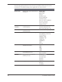
1
USER GUIDE
Trimble® TDL 450L/450H Radio
Contact Information
Trimble Navigation Limited
Engineering & Construction group
5475 Kellenburger Road
Dayton, Ohio 45424-1099
U.S.A
Tel: 800-538-7800 (U.S.A toll free)
+1-937-245-5600 Phone
+1-937-233-9004 Fax
www.trimble.com/global-services/
Support hours are 8 am to 5 pm Pacific Time. Please visit our website for
up-to-date news and product announcements. Firmware and software
upgrades are available from our website, usually free of charge.
Legal notices
©2013, Trimble Navigation Limited. All rights reserved. Trimble is a
trademark of Trimble Navigation Limited, registered in the United
States and in other countries. TRIMMARK and TRIMTALK are
trademarks of Trimble Navigation Limited. Microsoft, Windows, and
Windows Vista are either registered trademarks or trademarks of
Microsoft Corporation in the United States and/or other countries. All
trademarks are the property of their respective owners.
Warranty
One-Year limited warranty
This warranty gives you specific legal rights. You may also have other
rights which vary from state to state or area to area.
Trimble warrants TDL family products, inclusive of cables and batteries,
against defects in materials and workmanship for a period of one year
from receipt by the end-user.
Exclusions
Should Trimble be unable to repair or replace the product within a
reasonable amount of time, a refund of the purchase price may be given
upon return of the product.
The warranty on your radio shall not apply to defects resulting from:
Canada
This digital apparatus does not exceed the Class B limits for radio noise
emissions from digital apparatus as set out in the radio interference
regulations of the Canadian Department of Communications.
Le présent appareil numérique n’émet pas de bruits radioélectriques
dépassant les limites applicables aux appareils numériques de Classe B
prescrites dans le règlement sur le brouillage radioélectrique édicté par
le ministère des Communications du Canada.
Europe
This product has been tested and found to comply with the
requirements for a Class B device pursuant to European Council
Directive 1999/5/EC on R&TTE, thereby satisfying the requirements
for CE Marking and sale within the European Economic
Area (EEA). These requirements are designed to provide
reasonable protection against harmful interference when
the equipment is operated in a residential or commercial
environment, and to ensure that the equipment is safe.
Australia and New Zealand
This product conforms with the regulatory requirements of the
Australian Communications and Media Authority (ACMA)
EMC framework, thus satisfying the requirements for
C-Tick Marking and sale within Australia and New Zealand.
Notice to Our European Union Customers
For product recycling instructions and more information,
please go to www.trimble.com/ev.shtml.
Recycling in Europe: To recycle Trimble WEEE (Waste Electrical and
Electronic Equipment, products that run on electrical
power.), Call +31 497 53 24 30, and ask for the “WEEE
Associate”. Or, mail a request for recycling instructions to:
Trimble Europe BV
c/o Menlo Worldwide Logistics
Meerheide 45
5521 DZ Eersel, NL
• Improper or inadequate maintenance by the customer
• Unauthorized modification, negligence, or misuse
• Operation outside of the environment specifications
Warranty limitations
This warranty set forth above is exclusive and no other warranty,
whether written or oral, is expressed or implied. Trimble specifically
disclaims the implied warranties of merchantability and fitness for a
particular purpose.
Notices
Class B Statement – Notice to Users. This equipment has been tested and
found to comply with the limits for a Class B digital device, pursuant to
Part 15 of the FCC rules. These limits are designed to provide reasonable
protection against harmful interference in a residential installation.
This equipment generates, uses, and can radiate radio frequency energy
and, if not installed and used in accordance with the instructions, may
cause harmful interference to radio communication. However, there is
no guarantee that interference will not occur in a particular installation.
If this equipment does cause harmful interference to radio or television
reception, which can be determined by turning the equipment off and
on, the user is encouraged to try to correct the interference by one or
more of the following measures:
• Reorient or relocate the receiving antenna.
• Increase the separation between the equipment and the receiver.
• Connect the equipment into an outlet on a circuit different from that
to which the receiver is connected.
• Consult the dealer or Trimble directly for help.
Changes and modifications not expressly approved by the manufacturer
or registrant of this equipment can void your authority to operate this
equipment under Federal Communications Commission rules.
2
October 2013
TDL 450L/TDL 450H User Guide
Safety Information
Before you use your radio, ensure that you have read and understood this publication, as
well as safety requirements.
CAUTION – A license is required before operating radio communication equipment.
Warnings and cautions
An absence of specific alerts does not mean that there are no safety risks involved.
Always follow the instructions that accompany a Warning or Caution. The information
they provide is intended to minimize the risk of personal injury and/or damage to the
equipment. In particular, observe safety instructions that are presented in the following
formats:
WARNING – A Warning alerts you to a likely risk of serious injury to your person and/
or damage to the equipment. A warning identifies the nature of the risk and the extent
of possible injury and/or damage. It also describes how to protect yourself and/or the
equipment from this risk. Warnings that appear in the text are repeated at the front of the
manual.
CAUTION – A Caution alerts you to a possible risk of damage to the equipment and/or loss of
data. A Caution describes how to protect the equipment and/or data from this
Exposure to radio frequency energy
The radio is designed to comply with the following national and international standards
and guidelines regarding exposure of human beings to radio frequency electromagnetic
energy, in addition to protection against harmful interference of neighboring electrical
equipment:
• FCC Report and Order FCC 96-326 (August, 1996)
• American National Standards Institute (C95.3-1992)
• National Council on Radiation Protection and Measurement (NCRP - 1986)
• International Commission on Non-ionizing Radiation Protection (ICNRP - 1986)
• European Committee for Electrotechnical Standardization (CENELEC)
• FCC CFR47 Part 15
• FCC CFR47 Part 90
• Industry Canada RSS 119
• ETSI EN 300 113-2
• ETSI EN 300 489
• ACA AS/NZS 4295
• iDA Spec 111
• OFTA STD-1E
• RRC CMII
Contact your sales representative for model specific country approval.
To assure optimal radio performance and to ensure that exposure to RF energy is within
the guidelines in the above standards, observe the following operating procedures:
3
TDL 450L/TDL 450H User Guide
• Do not operate a transceiver when someone is within the distance noted below of the
antenna (unity gain).
– 120 cm (approximately 4 ft) for the TDL 450H radio @ 35 W
– 30 cm (approximately 12 in) for the TDL 450L/TDL 450H radios
@ 2 W – 60 cm (approximately 2 ft) for TDL 450L/TDL 450H radio @ 4 W
– 15 cm (approximately 6 in) for the TDL 450L radio @ 1 W
• Do not operate the transceiver unless all RF connectors are secure and any open
connectors are properly terminated.
• Avoid contact with the antenna while operating the transceiver.
• Do not operate the transceiver with a damaged antenna. If a damaged antenna comes
in contact with the skin, a minor burn may result.
• Do not operate the equipment near electrical blasting caps or in an explosive
atmosphere.
• Antennas are excellent conductors of electricity, so use extreme caution when
operating near power lines and other sources of electric current or during stormy
weather.
CAUTION – Changes or modifications not expressly approved by the FCC could void the user’s
authority to operate the equipment.
Exposure to hot surfaces
The TDL 450H enclosure and heat sink may become very hot during operation, depending
on the air temperature, transmit power, and transmission duty cycle. Turn off the unit and
let it cool before handling. Always use the heat-resistant handle to hold or move the TDL
450H radio.
Rechargeable batteries
The radio uses a 12 V, deep-discharge, lead-acid battery (portable power battery).
CAUTION – Storing batteries for an extended time in a discharged state damages them.
Note – For specific safety information, refer to the documentation included with your battery.
WARNING – Do not damage the battery. A damaged battery can cause an explosion or fire,
and can result in personal injury and/or property damage. To prevent injury or damage:
•
•
•
•
•
•
Do not use or charge the battery if it appears to be damaged. Signs of damage include,
but are not limited to, discoloration, warping, and leaking battery fluid.
Do not expose the battery to fire, high temperature, or direct sunlight.
Do not immerse the battery in water.
Do not use or store the battery inside a vehicle during hot weather.
Do not drop or puncture the battery.
Do not open the battery or short-circuit its contacts.
WARNING – Avoid contact with the battery if it appears to be leaking. Battery fluid is
corrosive, and contact with it can result in personal injury and/or property damage. To
prevent injury or damage:
•
•
4
If the battery leaks, avoid contact with the battery fluid.
If battery fluid gets into your eyes, immediately rinse your eyes with clean water and seek
TDL 450L/TDL 450H User Guide
•
medical attention. Do not rub your eyes!
If battery fluid gets onto your skin or clothing, immediately use clean water to wash off
the battery fluid.
WARNING – Charge and use the rechargeable battery only in strict accordance with
the instructions. Charging or using the battery in unauthorized equipment can cause an
explosion or fire, and can result in personal injury and/or equipment damage. To prevent
injury or damage:
•
•
•
•
•
Do not charge or use the battery if it appears to be damaged or leaking.
Charge the battery only in a Trimble product that is specified to charge it. Ensure that you
follow all instructions that are provided with the battery charger.
Discontinue charging a battery that gives off extreme heat or a burning odor.
Use the battery only in Trimble equipment that is specified to use it.
Use the battery only for its intended use and according to the instructions in the product
documentation.
CAUTION – Do not use any battery charger as a power supply for any radio. This may damage
the radio. Do not recharge any battery while it is connected to a radio.
Transmission Rules and Regulations
Licensing requirements
It is the responsibility of the owner to comply with applicable rules and regulations
concerning the operation of a radio transmitter. In the United States, the FCC regulates
the licensing of this equipment.
The TDL 450L and TDL 450H transceivers use extended frequencies and may contain
functions that are not operational in the United States and its territories. Users should
check with the radio authority of the country of operation for any restrictions that might
apply.
Application for a license is made by submitting FCC Form 600 along with evidence of
frequency coordination (if required) and applicable fees. Similar licensing requirements
exist worldwide. Penalties for broadcasting without a license can be severe, and may
include the confiscation of your radio.
For more information, contact our customer service department.
WARNING – Always obey local licensing requirements and restrictions. It is illegal to
transmit in the United States while CSMA is turned off. CSMA is not required within the
European Union and should be turned off.
Equipment compliances
The radios have been tested and found to comply with Parts 15 and 90 of Title 47 of the
Code of Federal Regulations. They have also been tested and found compliant for type
certification and approval in many other countries worldwide.
For more information concerning our worldwide compliances, contact customer support.
5
TDL 450L/TDL 450H User Guide
Being part of the RF community
Operation of a licensed radio product makes you a member of the RF community.
Be aware that virtually all frequencies licensed are provided on a shared basis with
other users. Each frequency dedicated specifically to RTK surveying activities has
certain restrictions and limitations. For complete information, refer to the appropriate
documentation from the licensing agency in your country of operation, e.g., Part 90, Title
47, of the Code of Federal Regulations.
Most frequencies sharing data transmissions and voice transmissions give priority to
voice users. Be mindful of the persistent nature of a GPS RTK data transmission and
always limit your RF transmission output power when performing close-in survey
situations to avoid interference with co-channel users. Trimble recommends using the
low RF power setting for construction site and other line-of-site surveys with baselines
less than two miles (depending on terrain).
WARNING – If you are in conflict with a co-channel user, select another frequency to avoid
formal actions by government agencies. In most cases, you are required to vacate a frequency
upon complaint by a shared channel voice user.
Most survey operations are itinerant in that the system is moved on a frequent basis.
For fixed system installations, you should not use frequencies set aside for itinerant
operations, but should coordinate a frequency based on the fixed area operation.
Regulations differ from country to country, please be aware of the local regulations before
using radio equipment.
Automatic station identification
For operation in the United States, the FCC requires that radio transmitters broadcast a
station identifier every 15 minutes. The station identifier is the call sign assigned to you
on the station license.
The radios support the broadcast of station identification in a manner that meets the
requirements of the FCC. Upon receipt of equipment, use the TDLCONF software to
program your FCC call sign into the configuration of the radio. This is only required for
transmitters.
The call sign is transmitted every 15 minutes in Morse code. It is not included in any
data packet and so is not processed by the receiving radio. However, data transmission is
interrupted for a few seconds while the call sign is being transmitted. If you leave the Call
sign field blank (on the TDLCONF Identification screen), the radio programmed with this
configuration file will not transmit any call sign.
WARNING – Failure to transmit your station identification is in violation of FCC regulations.
If you are operating outside the United States, check with the local authorities if you need to
transmit a call sign.
Carrier Sense Multiple Access (CSMA)
CSMA is a technology implemented in the radios to meet the United States Federal
Communication Commission (FCC) transmitter requirements. It is illegal to transmit on
any UHF radio within the United States without CSMA enabled. CSMA holds off the radio
6
TDL 450L/TDL 450H User Guide
transmission if the frequency is currently being used by a co-channel user. On occasion, you
may note that the radio broadcasts stop for short periods of time. Most often, this is a case
of co-channel interference and the radio is holding off broadcasts due to the FCC-mandated
CSMA.
Note – You should turn CSMA off when transmitting within the European Union.
GPS RTK equipment is designed to function with intermittent gaps in the data. Heavy cochannel use may limit the ability of the radio to transmit the required information. In areas of
heavy co-channel usage, try changing channels to a less used frequency.
7
TDL 450L/TDL 450H User Guide
Contents
Safety Information . . . . . . . . . . . . . . . . . . . . . . . . . . . . . . . . . . . . . . . . . . . . . . . . . . . . . . 3
Introduction . . . . . . . . . . . . . . . . . . . . . . . . . . . . . . . . . . . . . . . . . . . . . . . . . . . . . . . . . . . 9
Note about this guide . . . . . . . . . . . . . . . . . . . . . . . . . . . . . . . . . . . . . . . . . . . . . . . . . . . . . . . . . . . . . . . . . . . . . . . . . 9
Technical Support. . . . . . . . . . . . . . . . . . . . . . . . . . . . . . . . . . . . . . . . . . . . . . . . . . . . . . . . . . . . . . . . . . . . . . . . . . . . . 9
Your Comments. . . . . . . . . . . . . . . . . . . . . . . . . . . . . . . . . . . . . . . . . . . . . . . . . . . . . . . . . . . . . . . . . . . . . . . . . . . . . . . 9
Overview. . . . . . . . . . . . . . . . . . . . . . . . . . . . . . . . . . . . . . . . . . . . . . . . . . . . . . . . . . . . . 10
Features. . . . . . . . . . . . . . . . . . . . . . . . . . . . . . . . . . . . . . . . . . . . . . . . . . . . . . . . . . . . . . . . . . . . . . . . . . . . . . . . . . . . . . 10
Compatibility. . . . . . . . . . . . . . . . . . . . . . . . . . . . . . . . . . . . . . . . . . . . . . . . . . . . . . . . . . . . . . . . . . . . . . . . . . . . . 10
Enhanced user interface . . . . . . . . . . . . . . . . . . . . . . . . . . . . . . . . . . . . . . . . . . . . . . . . . . . . . . . . . . . . . . . . . . 10
Fast over-the-air data rate . . . . . . . . . . . . . . . . . . . . . . . . . . . . . . . . . . . . . . . . . . . . . . . . . . . . . . . . . . . . . . . . 10
User-selectable RF output . . . . . . . . . . . . . . . . . . . . . . . . . . . . . . . . . . . . . . . . . . . . . . . . . . . . . . . . . . . . . . . . 10
Rugged construction. . . . . . . . . . . . . . . . . . . . . . . . . . . . . . . . . . . . . . . . . . . . . . . . . . . . . . . . . . . . . . . . . . . . . . 10
Software compatibility . . . . . . . . . . . . . . . . . . . . . . . . . . . . . . . . . . . . . . . . . . . . . . . . . . . . . . . . . . . . . . . . . . . . 10
Configuring the Radios . . . . . . . . . . . . . . . . . . . . . . . . . . . . . . . . . . . . . . . . . . . . . . . . . 11
TDLCONF configuration software . . . . . . . . . . . . . . . . . . . . . . . . . . . . . . . . . . . . . . . . . . . . . . . . . . . . . . . . . . . . 11
Factory default settings. . . . . . . . . . . . . . . . . . . . . . . . . . . . . . . . . . . . . . . . . . . . . . . . . . . . . . . . . . . . . . . . . . . . . . . 11
Setup in the Office. . . . . . . . . . . . . . . . . . . . . . . . . . . . . . . . . . . . . . . . . . . . . . . . . . . . . . . . . . . . . . . . . . . . . . . . . . . . 12
Setting up in the Field . . . . . . . . . . . . . . . . . . . . . . . . . . . . . . . . . . . . . . . . . . . . . . . . . . . . . . . . . . . . . . . . . . . . . . . . 13
Tripod mounts . . . . . . . . . . . . . . . . . . . . . . . . . . . . . . . . . . . . . . . . . . . . . . . . . . . . . . . . . . . . . . . . . . . . . . . . . . . 14
Antenna and antenna mount . . . . . . . . . . . . . . . . . . . . . . . . . . . . . . . . . . . . . . . . . . . . . . . . . . . . . . . . . . . . . 14
Data/Power cable . . . . . . . . . . . . . . . . . . . . . . . . . . . . . . . . . . . . . . . . . . . . . . . . . . . . . . . . . . . . . . . . . . . . . . . . 16
Indicator LEDs . . . . . . . . . . . . . . . . . . . . . . . . . . . . . . . . . . . . . . . . . . . . . . . . . . . . . . . . . . . . . . . . . . . . . . . . . . . 16
Enclosure. . . . . . . . . . . . . . . . . . . . . . . . . . . . . . . . . . . . . . . . . . . . . . . . . . . . . . . . . . . . . . . . . . . . . . . . . . . . . . . . . 16
Antenna connector . . . . . . . . . . . . . . . . . . . . . . . . . . . . . . . . . . . . . . . . . . . . . . . . . . . . . . . . . . . . . . . . . . . . . . . 17
Battery care . . . . . . . . . . . . . . . . . . . . . . . . . . . . . . . . . . . . . . . . . . . . . . . . . . . . . . . . . . . . . . . . . . . . . . . . . . . . . . . . . . 17
Charging . . . . . . . . . . . . . . . . . . . . . . . . . . . . . . . . . . . . . . . . . . . . . . . . . . . . . . . . . . . . . . . . . . . . . . . . . . . . . . . . . 17
Operating the Radio. . . . . . . . . . . . . . . . . . . . . . . . . . . . . . . . . . . . . . . . . . . . . . . . . . . . 19
Turning the radio on and off . . . . . . . . . . . . . . . . . . . . . . . . . . . . . . . . . . . . . . . . . . . . . . . . . . . . . . . . . . . . . . . . . . 19
User interface . . . . . . . . . . . . . . . . . . . . . . . . . . . . . . . . . . . . . . . . . . . . . . . . . . . . . . . . . . . . . . . . . . . . . . . . . . . . . . . . 19
Automatic Channel Selection. . . . . . . . . . . . . . . . . . . . . . . . . . . . . . . . . . . . . . . . . . . . . . . . . . . . . . . . . . . . . . . . . 23
Manual Frequency Entry . . . . . . . . . . . . . . . . . . . . . . . . . . . . . . . . . . . . . . . . . . . . . . . . . . . . . . . . . . . . . . . . . . . . . 24
CSMA. . . . . . . . . . . . . . . . . . . . . . . . . . . . . . . . . . . . . . . . . . . . . . . . . . . . . . . . . . . . . . . . . . . . . . . . . . . . . . . . . . . . . . . . 24
Security code. . . . . . . . . . . . . . . . . . . . . . . . . . . . . . . . . . . . . . . . . . . . . . . . . . . . . . . . . . . . . . . . . . . . . . . . . . . . . . . . . 24
Edit configuration . . . . . . . . . . . . . . . . . . . . . . . . . . . . . . . . . . . . . . . . . . . . . . . . . . . . . . . . . . . . . . . . . . . . . . . . . . . . 24
Scrambling. . . . . . . . . . . . . . . . . . . . . . . . . . . . . . . . . . . . . . . . . . . . . . . . . . . . . . . . . . . . . . . . . . . . . . . . . . . . . . . . . . . 25
Forward Error Correction . . . . . . . . . . . . . . . . . . . . . . . . . . . . . . . . . . . . . . . . . . . . . . . . . . . . . . . . . . . . . . . . . . . . 25
Previous Error. . . . . . . . . . . . . . . . . . . . . . . . . . . . . . . . . . . . . . . . . . . . . . . . . . . . . . . . . . . . . . . . . . . . . . . . . . . . . . . . 25
Automatic Power Management. . . . . . . . . . . . . . . . . . . . . . . . . . . . . . . . . . . . . . . . . . . . . . . . . . . . . . . . . . . . . . . 26
Tips and Techniques for Best Performance. . . . . . . . . . . . . . . . . . . . . . . . . . . . . . . . . . 28
Antenna . . . . . . . . . . . . . . . . . . . . . . . . . . . . . . . . . . . . . . . . . . . . . . . . . . . . . . . . . . . . . . . . . . . . . . . . . . . . . . . . . . . . . 28
Line loss . . . . . . . . . . . . . . . . . . . . . . . . . . . . . . . . . . . . . . . . . . . . . . . . . . . . . . . . . . . . . . . . . . . . . . . . . . . . . . . . . . . . . 28
Power supplies . . . . . . . . . . . . . . . . . . . . . . . . . . . . . . . . . . . . . . . . . . . . . . . . . . . . . . . . . . . . . . . . . . . . . . . . . . . . . . . 28
Equipment care . . . . . . . . . . . . . . . . . . . . . . . . . . . . . . . . . . . . . . . . . . . . . . . . . . . . . . . . . . . . . . . . . . . . . . . . . . . . . . 28
Use with Machinery and Vehicles . . . . . . . . . . . . . . . . . . . . . . . . . . . . . . . . . . . . . . . . . 29
Vibration damping . . . . . . . . . . . . . . . . . . . . . . . . . . . . . . . . . . . . . . . . . . . . . . . . . . . . . . . . . . . . . . . . . . . . . . . . . . . 29
Mounting inside/outside vehicle cabin. . . . . . . . . . . . . . . . . . . . . . . . . . . . . . . . . . . . . . . . . . . . . . . . . . . . . . . . 29
DC power supply with power conditioner . . . . . . . . . . . . . . . . . . . . . . . . . . . . . . . . . . . . . . . . . . . . . . . . . . . . 29
Protection from electromagnetic interference . . . . . . . . . . . . . . . . . . . . . . . . . . . . . . . . . . . . . . . . . . . . . . . . 29
Pinouts and Connectors . . . . . . . . . . . . . . . . . . . . . . . . . . . . . . . . . . . . . . . . . . . . . . . . . 30
Antenna . . . . . . . . . . . . . . . . . . . . . . . . . . . . . . . . . . . . . . . . . . . . . . . . . . . . . . . . . . . . . . . . . . . . . . . . . . . . . . . . . . . . . 30
Technical Specifications . . . . . . . . . . . . . . . . . . . . . . . . . . . . . . . . . . . . . . . . . . . . . . . . . 31
8
TDL 450L/TDL 450H User Guide
Introduction
This manual describes how to set up and use the Trimble® TDL 450L or 450H radio. The
radios are advanced, high speed, wireless data links that are designed specifically for
GNSS/RTK applications, but are also appropriate for many other applications requiring
digital data links. Your success in using the radios is the primary goal of Trimble. Trimble
stands behind its products by providing expert support and service. Your comments and
questions are welcome.
This guide provides information concerning the use of the following radios:
• TDL 450L
Model numbers ADLV-1 (410 to 430 MHz) and ADLV-2 (430 to 470 MHz)
• TDL 450H
Model numbers ADLP-1 (410 to 430 MHz) and ADLP-2 (430 to 470 MHz)
This guide is written for the first-time user and gives details concerning system setup,
operation, and maintenance. We urge you to take the time to review this short manual
completely before you set up the system.
Note about this guide
We believe that the TDL 450L/450H systems provide the best value and performance for
the user. As such, we provide our equipment in complete turnkey systems, including all of
the items necessary for operation with your GPS.
You may have purchased this radio from a third-party supplier. On occasion, the bundled
product provided by these sources may differ from the kits provided directly from
Trimble. If this guide does not accurately reflect the equipment that you received, please
contact your supplier for specific instructions concerning the setup of items that differ.
Technical Support
If you have a problem and cannot find the information you need in the product
documentation, contact your local dealer or go to the Support area of the Trimble website
(www.trimble.com/global-services/). Product updates, documentation, and any support
issues are available for download.
Your Comments
Your feedback about the supporting documentation helps us to improve it with each
revision. Email your comments to [email protected].
9
TDL 450L/TDL 450H User Guide
Overview
Features
Compatibility
• Facilitates radio equipment mix and match
• Interoperable with Trimble radio products, Pacific Crest (RFM, PDL, and ADL), and
SATEL
• All models support 12.5 kHz and 25 kHz channel bandwidth communications
• Available in two bands: 410 MHz–430 MHz and 430 MHz–470 MHz
• Provides upgrade path for existing installations
Enhanced user interface
• Backlit LCD display and five-button navigation interface
• View and change radio channel, modulation, and protocol types
• Monitor signal levels, baud rates, and other parameters
Fast over-the-air data rate
• Up to 19,200 bits per second
• Reduced latency provides better GNSS position information
• Shorter transmit times reduces power consumption for longer battery life
User-selectable RF output
TDL 450L: Select between 0.1 W, 0.5 W, 1 W, 2 W, and 4 W
TDL 450H: Select between low power (2 W), and four configurable power output settings
from 2 W to 35 W
• Increase range by switching to a higher output power
• Increase battery life by reducing output power when you do not need the range
Rugged construction
Designed specifically for real-world working environments
• All metal construction and shock-mounted electronics ensure highest reliability and
EMI-resistance.
• Watertight, corrosion-resistant connectors stand up to bad weather conditions.
Software compatibility
Current versions of the following software were tested and verified for compatibility with
Windows® 7, Windows XP, and the Business Edition of the Windows Vista® operating
systems:
• TDLCONF
• PCC Range Estimator
10
TDL 450L/TDL 450H User Guide
Configuring the Radios
TDLCONF configuration software
TDLCONF is the software application for configuring and troubleshooting all TDL radios.
Running the TDLCONF software on a computer attached through a serial cable to a TDL
radio enables you to check the status of the radio, enter receive-only channel tables, and
set radio parameters such as channel bandwidth and output power. Channel tables for
transmission of data must be obtained from authorized Trimble dealers. If your radio did
not come with a channel table already installed, you can obtain one from your dealer and
then import it using the TDLCONF software.
The latest version is available for free download from www.trimble.com. The TDLCONF
User Guide is also available on the Trimble website. A user guide that describes how to
configure the TDL 450L radio is available by running the TDLCONF software and then
selecting Help / User Guide.
Factory default settings
To return the radio to its factory default configuration, use the TDLCONF software. Click
Restore Factory to the right of the screen and then click Program. The following table
shows the factory default settings:
11
Description
Default Setting
Device Status
Battery status
Chanel/Frequency
Channel 01 and frequency (MHz)
Channel Tx Frequency
Channel No. and frequency (MHz)
Data Protocol
Transparent EOT (End of Transmission)
Radio Link Rate
9600
Operation Mode (Trimble protocol)
Base/Rover
Sensitivity
High (Rover)
Rx LED Meaning
Signal Received
Serial Baud
38000
Advanced Menus
Hide
CSMA
On
Security Code
Off
Edit Configuration
Enabled
Scrambling
On
Forward Error Correction
On
Language Select (TDL 450H only)
English
TDL 450L/TDL 450H User Guide
Setup in the Office
1.
2.
3.
4.
5.
6.
7.
12
Plug the radio’s desktop power supply into the wall. You may alternatively use an approved
12 Volt battery for power. But you must never power a radio with a battery while it is being
recharged. This will damage the battery.
Attach the desktop power supply’s (or battery’s) SAE connector to the radio programming
cable’s SAE connector.
Attach the programming cable’s DE-9 connector into a serial port on your PC. If your PC
does not have a serial port, you should use a serial-to-USB adaptor.
Attach the programming cable’s LEMO plug (with the red dot facing up) into the bottom of
the radio. This will turn the radio on.
Install TDLCONF, available for free download from www.trimble.com/global-services/
Launch TDLCONF and refer to its user guide for instructions on connecting to TDL radios.
The user guide is displayed when you click Help > User Guide on TDLCONF’s main menu.
In most cases, you simply click the Connect button on the right of the TDLCONF main
screen.
After connecting to the radio for the first time you should click File > Export and save a
copy of the radio’s original configuration to your PC. You also can return the radio to its
factory configuration by clicking File > Import and selecting this file. You will not lose any
channel tables or personalized configurations such as Owner Name or Call Sign by
importing a configuration file.
TDL 450L/TDL 450H User Guide
Setting up in the Field
1.
2.
3.
4.
5.
Attach the antenna to the radio, either directly to the top of the radio or to an antenna cable.
Attach the radio to your tripod using the tripod clip on the back of the radio. See the figure be
low for setup suggestions.
Connect the radio to the source of the data you will transmit, for example, a GPS receiver, using
the data/power cable. The TDL 450L and TDL 450H radios use the same data
connector – with the same pinouts - found on the PDL HPB radio. This makes the radios
compatible with existing HPB data cables.
Join the data/power cable’s SAE connector to the 12 Volt battery’s SAE connector. This will turn
the radio on. If the radio had previously been powered on and then off, turn it on again by
pressing the On/Off button in the center of the front panel.
The TDL 450L and TDL 450H’s user interface allows you to configure and trouble
shoot your radio in the field. The top row of the radio’s LCD displays the name of the currently
selected firmware function. Press the right or left buttons on the front panel to display other
functions available in the TDL. The bottom row displays the various options for the
selected function. The currently active setting is marked with an asterisk. To select another
option for the displayed function, press the up or down button to display the desired parameter.
Then press Enter to reconfigure the radio to use this new parameter.
RF
Antenna
ADL Radio
Battery
ADL Vantage
Data / Power Cable
To Battery
To GPS Unit
Note – If you operate the TDL 450H in a fixed installation, you should attach it to a
wall with the wall mount accessory (P/N 84269). The wall mount includes two small
fans that move air over the rear of the radio to reduce its internal temperature when
transmitting at high duty cycle.
13
TDL 450L/TDL 450H User Guide
Tripod mounts
Each TDL 450L radio includes a tripod clip on the rear of the radio. Insert the clip into a
slot on the tripod:
Each TDL 450H radio includes a high-impact polymer handle with built-in tripod clip.
Insert the clip into a slot on the tripod:
Antenna and antenna mount
The most important activity in setting up a radio transmitter is determining the placement
and type of the antenna. Where flexibility permits, always place the antenna on the highest
point available and always select an antenna with a gain pattern (more on this later) which
optimizes the coverage. In general, use a directional gained antenna such as a Yagi for a
point-to-point fixed location application and a gained omnidirectional antenna for mobile
point-to-point or point-to-multipoint communication systems.
Note – Safety Concerns
- Be aware of power lines or other obstacles that can inadvertently come in contact with the
antenna and cause potentially lethal conditions.
- Guy-wire antenna masts higher than 10 feet.
- Use lightning arrestors for equipment and personal protection if erecting an antenna in areas
prone to lightning.
- Installation of antennas on buildings or other structures (towers, etc.) must be done in
accordance with local building regulations. Contact a local antenna installer who is familiar
with building codes and proper antenna installation for any permanent installation.
14
TDL 450L/TDL 450H User Guide
If you have an antenna with a male TNC connector, you can attach it directly to the RF
connector on the top of the radio. We highly recommend, however, that you elevate the
RF antenna as much as possible. The most common set up is similar to that shown in the
following illustration where an antenna cable with male TNC connector is attached to the
radio. The other end of this cable is attached to a tripod or elevated section of range pole.
The RF antenna is then attached to the end of the cable. Trimble offers an antenna cable
that attaches to standard 5/8-in threaded tripods and range poles and antennas with NMO
connectors.
Inspect the antenna center push-pin contact to ensure that it makes good contact with
the antenna mount. A good antenna connection is critical to system performance.
The TDL 450H radio includes an antenna detection/VSWR measurement feature. VSWR
(Voltage Standing Wave Ratio) is a measurement of the ratio of RF energy transmitted
out of the device over the RF energy reflected back into the device. The higher the ratio,
the lower the amount of transmitted energy, the poorer the range and the greater the
danger that the RF energy reflected back into the device will damage components. The
TDL 450H radio measures VSWR prior to first transmit. The user is notified on the LCD’s
Device Status screen to check the antenna if VSWR>4:1. The TDL 450H radio will reduce
its TX power to 2W if VSWR>4:1. The user is also notified that no antenna is detected if
VSWR>8.
Note – Always ensure that an antenna is connected before transmitting with any radio. A
good field practice is to attach the antenna before you turn on the radio and then turn off the
radio before you detach the antenna. Using a gained antenna raises the Effective Isotropic
Radiated Power (EIRP) of the radio. Ensure that the resultant EIRP does not exceed your
licensed limit.
15
TDL 450L/TDL 450H User Guide
Data/Power cable
The radio is connected to a data source, such as a GNSS receiver, using a data/power
cable (see below). This cable is available with different connectors for attaching to a large
variety of data sources. Contact your sales representative for selecting the best cable to
meet your needs:
Data Source Connector
Radio Connector
SAE Power Connector
Each radio data/power cable also connects the radio (and in some cases, the data source)
to external power through an SAE-type connector. Trimble strongly recommends you use
the external battery, which includes an SAE connector. It is sold both separately and as
part of the battery/charger kits.
Indicator LEDs
LED
Description
Tx
Shows that the radio is broadcasting.
In most GPS RTK applications, the Tx LED flashes approximately once per second.
Pwr
Shows the power status and also provides a high and low external voltage supply
indicator.
When lit, power is turned on. If the power is too high or too low, the LEDs will flash
the number of the Error Code (see page 26). The PWR LED blinks when the external
voltage drops to a level determined using TDLCONF software. (The default level is 10
VDC.)
If the PWR LED does not turn on/off when pressing the On/Off button on the radio’s
front panel, inspect the external voltage supply. The minimum voltage required by the
radio is 9 VDC.
Rx
Shows that the radio is receiving signals from another radio or from a source of
interference.
The default is Signal received, but you can reset the radio so that when its Rx LED flashes it
means Data packets received. You can reset the meaning either through the radio or with
the TDLCONF software.
During normal operation, the Rx LED flashes at once per second to show reception of
transmissions from the transmitting radio. If the Rx LED is on continuously, a source of
interference may be affecting the radio’s ability to receive data.
To reduce or eliminate the interference, reposition the antenna, or change to another
channel at both the transmitter and receiver.
Enclosure
The radio enclosure is made from a tough, impact-resistant aluminum alloy. The
enclosure receives an anti-corrosion treatment and is further protected with a chemicaland scratch-resistant polyurethane coating. Elastomer end caps provide the first level of
shock protection for the internal components. An internal isolation system reduces the
effects of vibration on the radio receiver board.
16
TDL 450L/TDL 450H User Guide
Antenna connector
The integrated antenna connector provides an industry standard TNC-female RF
connector that is compatible with a wide range of mobile whip antennas. Trimble also
sells cables that connect the radio to remote antennas.
Battery care
The TDL 450L Battery/Charger kit includes a 12 V, 12-AHr, battery. The TDL 450H
Battery/Charger kit includes a 12 V, 35-AHr, battery. Both are deep-cycle, deep-discharge,
sealed lead-acid batteries, also known as portable power batteries. Both batteries provide
all-day operation for the respective radios and can be recharged approximately 300 times
over a period of three years if proper care is maintained.
A deep-discharge battery will last longer if it is never fully discharged during use and
always fully charged before storage. If the battery is discharged entirely, the capacity will
diminish. The TDL 450H radio will maintain the transmit power level as the battery
voltage is reduced. Transmitting at a high power level for a long period of time may cause
the battery to reach the automatic shut off level before eight hours of use and will need to
be recharged.
If you use your own batter, select a deep-discharge battery with a minimum capacity of 30
AHr. If necessary, you can use an automotive battery, but it will be damaged by repetitive
discharge/charge cycles. An automotive battery will lose capacity in just a few cycles.
Trimble does not recommend this practice.
To protect the battery from over-discharge, a TDL 450L or TDL 450H will flash a low
voltage warning when the input voltage declines to 10 V DC. If the voltage continues to
decline, the radio will shut itself off at 9 V DC. At 10 V DC, the LEDs on the front of the
radio will flash twice, pause, flash twice again, pause, etc. indicating low input voltage. If a
radio has shut itself off because of low input voltage, it will automatically turn itself back
on when the voltage returns to 9 V DC or higher.
The 10 V warning and 9 V shut-off levels are the factory defaults. If you wish, you can use
TDLCONF software (Radio Link - Advanced screen) to configure other power levels. The
minimum shut off level for an TDL 450H is 9 V DC and cannot be changed. You can input
a lower value for the TDL 450L, but please be advised that values lower than 9 V might
permanently damage your battery.
Charging
The charger supplied with the radio Battery/Charger kit provides two-stage charging and
must be connected to the battery following every full day of operation to ensure good
battery life and performance. The first stage quickly charges the battery to capacity, and
the second stage trickle charges the battery to maintain a full charge. It is important
to recharge your battery every time it is used. Do not allow a battery to remain in a
discharged state any longer than necessary.
It is important to periodically charge any battery that is stored for an extended length of
time. Storing batteries for an extended time in a discharged state damages them and will
17
TDL 450L/TDL 450H User Guide
reduce the capacity of the battery. To recharge a user-supplied battery, select a charger
of appropriate type. A battery charge designed for use with a deep-cycle, deep-discharge,
sealed lead acid battery may damage an automotive battery. An automotive battery
charger may not fully charge a deep-cycle, deed-discharge, sealed lead acid battery. Never
recharge any battery while it is connected to a radio as it could damage the radio and/or
the battery.
18
TDL 450L/TDL 450H User Guide
Operating the Radio
Turning the radio on and off
To turn on the radio, attach the radio to power using either the programming cable
(attached to wall/mains current) or the data/power cable (attached to the external
battery of the radio). Once the radio detects power on its data connector, it automatically
turns on and is ready for communication within 5 seconds. If the wall/mains current is
interrupted, the radio automatically turns itself on and resumes transmitting data within
5 seconds of power restoration. If the radio is attached to an antenna when the radio is
turned on, it automatically runs an antenna test before it will communicate. Wait until
this test is complete before transmitting any data.
To turn off the TDL 450L radio, either detach its power cable or depress the On/Off button
in the center of the front panel for 5 seconds..
To turn the radio on again, either press the On/Off button or remove and reinsert the
data/power cable.
The 35 Watt TDL 450H draws enough current to damage electrical components if it is
shut off improperly. If the data/power cable is disconnected from the battery while the
radio is powered on, electrical arcing can damage the battery terminal connectors on
the cable. If the data/power cable is disconnected from the radio while it is powered on,
arcing can damage the socket on the radio and the connector on the cable and can even
burn out some of the radio’s internal components.
Evidence of damage caused by improperly shutting off the TDL 450H is a blown fuse in
the power cable, pitting or blackening of the connectors or the inability to turn the radio
back on.
To avoid any damage, always turn the radio off by depressing the power switch on the
radio’s front panel BEFORE you remove the data/power cable from either the radio or
from the battery.
CAUTION – The TDL 450H enclosure and heat sink may become very hot during operation.
The radio’s temperature depends on the ambient temperature, RF power selection, and
transmission duty cycle. Turn off the unit and allow it to cool before handling. Always use
the heat-resistant handle to hold or move the TDL 450H radio.
19
TDL 450L/TDL 450H User Guide
User interface
The user interface includes three LEDs, an On/Off button, a two-row LCD display, four
scrolling buttons marked with arrows, and a central Enter button:
The LCD has a backlight that stays on for 20 seconds. The backlight must be on for the
Enter or arrow buttons to function. If the backlight is off, pressing any button turns it on.
To have the backlight stay on, click Advanced on the TDLCONF’s Serial Interface screen
and clear the Turn off radio LCD backlight after 20 seconds check box. Click the TDLCONF
Program button to program the radio with this change.
To save power, the LCD and keypad on the TDL 450H will automatically go into sleep
mode 5 minutes after the last keystroke (except while the radio is being configured by
TDLCONF). All other features, including the transmitter and LEDs, will continue to
function normally. To wake up the LCD and keypad, press the On/Off button for one
second. To turn the TDL 450H off when its LCD and keypad are in sleep mode, depress
the On/Off button for 5 seconds or remove the power cable.
The LCD displays information that is determined in any of five different ways:
• Settings such as the serial number and model number are written in the factory
• The battery status, signal strength, and error codes are constantly monitored by the
radio firmware
• The channel tables (including frequency and bandwidth) and maximum transmit
power are determined by your dealer
• Everything else can be set by you using the TDLCONF software
In addition, you can configure many radio settings using the buttons on the front panel
and the LCD. The top rows of the LCD display the name of the currently selected radio
configuration function. The bottom LCD rows display the various parameters you can
choose for the displayed function. Press the left or right arrows to scroll to different
functions. Press the up or down arrows to scroll to different choices for the displayed
function.
20
TDL 450L/TDL 450H User Guide
The following table describes the various functions available, and lists the choices for
each function. The default settings, where applicable, are shown in bold.
Function
Description
Parameter choices
Device Status
Displays radio status and identification
information
Battery status
Serial Number
Owner name
Call sign
Modulation type
Channel bandwidth
Transmitter status
Duty cycle (when a TRIMTALK
protocol is selected)
Internal temperature
Firmware version
Channel /
Frequency
Displays/selects channel number and
receive frequency
Channel No. and frequency (MHz)
Ch TX Frequency
Displays Tx freq (if different from the
channel’s Rx freq)
Channel No. and frequency (MHz)
Data Protocol
Displays/selects data protocol type
Trans EOT (End of Transmission)
AutoRover (TDL 450L only)
Manual Entry (TDL 450L only)
Trans EOC (End of Character)
Packet Switched
TRIMTALK™ 450S
TRIMMARK™ II/IIE
TT450S (HW)
TRIMMARK 3
SATEL
Trans FST
Radio Link Rate
Displays/selects bit rate for radio
transmission/reception
4800
8000
9600
16000
19200
Repeater Mode
Sets the radio to be a repeater
(non-Trimble) protocols
Off (Not a repeater)
Operation Mode
Sets the radio to be a repeater
(Trimble protocols)
Base/Rover
On (Is a repeater)
Base w/ One Rpt
Base w/Two Rpt
Repeater 1
Repeater 2
Sensitivity
Displays/selects radio squelch level
High (rover)
Moderate
Low (base)
21
TDL 450L/TDL 450H User Guide
Function
Description
Parameter choices
Transmit Power
Displays / selects transmitter power
level
Low power
Low intermediate power
Intermediate power
High intermediate power
High power
Rx LED Meaning
Serial Baud
Displays/selects what it means when
the Rx LED flashes
Signal received
Displays/selects serial baud rate of the
radio’s data port
2400
Data received
4800
9600
19200
38400
115200
Signal Strength
Displays strength of the received
Press the Enter button
signal (RSSI) in dBm
High:
RSSI > -90 dBm
Med:
-90 > RSSI >-110 dBm
Low:
-110 > RSSI > -150 dBm
Advanced Menus
Displays or conceals rarely used menus
Hide
CSMA
Displays/selects Carrier Sense Multiple
Access Settings
On
Security Code
Encrypts/Decrypts transmitted data
Off
(Not displayed if a Trimble protocol
is selected or if no code has been
programmed into the radio.)
On
Edit
Configuration
Enables/Disables configuration using
the radio interface
Enabled
Scrambling
Fills dead air with non-zero bits
On
(Not displayed if a Trimble protocol is
selected.)
Off
Turns Forward Error Corrections on/off
On
(Not displayed if a Trimble protocol is
selected.)
Off
Previous Error
Displays current error status
No Error
Language Select
(TDL 450H only)
Selects the display language
Show
FEC
Off
Disabled
English
Chinese
Russian
Antenna
Detection
Reduces TX power to 2W if antenna
reflects too much energy back into the
radio at first transmission
Disabled
Enabled
For the field-configurable functions, the available choices are displayed on the bottom
row of the LCD. The currently selected parameter is marked with an asterisk. To select a
different choice for the displayed function, scroll up or down with the arrow buttons and
press Enter when the required choice is displayed.
22
TDL 450L/TDL 450H User Guide
There are two ways to move to a different function screen:
• When viewing a display-only function, such as Device Status or Signal Strength, press
the left or right arrow.
• When viewing a display-and-select function, such as Channel/Freq or Data Protocol,
press the up/down arrows to display the currently selected parameter (marked with an
asterisk) in the second row. Then press either the left or right arrow to move to a new
function screen.
Note – If the currently selected parameter (shown with an asterisk) is not currently displayed
on the LCD, and the backlight is off, you have not pressed a button for more than 20 seconds,
you can scroll directly to the selected parameter by pressing the left or right arrow once. To
move to a new function screen, press the left or right arrow a second time.
To speed field configuration and to prevent the selection of unsupported radio
configurations, the user interface displays only those function settings that make sense
based on the settings chosen for previously displayed functions. What you choose for the
data protocol determines your options for radio link rate and repeater mode. For example,
if your channel table is set to 12.5 kHz channel spacing, and you select TT450S (HW) on
the Data Protocol screen, you cannot select a radio link rate (the Radio Link Rate screen
does not even appear) because the TT450S (HW) protocol works with 12.5 kHz channel
spacing only at 4800 bps. And because TT450S (HW) is a Trimble protocol, Trimblespecific “Operation Modes” (instead of “Repeater Modes”) are available for selection. If you
decide to undo any of these selections, press the left arrow to return to the Data Protocol
screen and then select a different protocol.
Although the radio modem supports both GMSK and 4FSK modulation, you cannot select
a modulation type with the user interface. The radio automatically selects the appropriate
modulation based on the channel bandwidth the channel table programmed into the
radio (displayed on the Device Status screen as CH BW: 12.5 or 25 kHz), the data
protocol, and the radio link rate. If you want to select a modulation type first and then an
appropriate channel bandwidth, protocol and link rate, use the TDLCONF software to
configure the radio.
Eight rarely changed functions are grouped together under Advanced Menus. In order
to speed everyday navigation, they are not displayed. The default values are indicated in
the table above. To make a change to any of these functions, go to the Advanced Menus
feature, press the down arrow until Show appears on the second line and then press the
Enter button. Press the right arrow sequentially to display these eight functions. To hide
these features, return to the Advanced Menus feature and then select the Hide option.
Automatic Channel Selection
Using the TDL 450L radio (but not the TDL 450H), you can have the radio automatically
select the channel with the strongest signal containing decipherable data, i.e., data
configured with the same protocol, modulation and link rate. This allows you to transmit
data on one radio and then lock onto that transmission without having to remember the
23
TDL 450L/TDL 450H User Guide
channel number or frequency. However, both radios must still be set to all other radio
parameters (radio protocol, Forward Error Correction, Scramble Control, etc.) in order to
communicate.
To use the Automatic Channel Selection feature, scroll to the Channel/Freq screen on the
TDL 450L front display. Go to the bottom of the channel table and press Enter when you
see one of the AutoRover options. Select the AutoRover 1 option when you want the radio
to automatically scan the entire channel table and select the frequency with the strongest
decodable signal. The AutoRover 1 option will perform one scan when the radio is turned
on, tune to the channel with the strongest signal containing decipherable data and stop
scanning. The AutoRover 2 option will perform a scan for the strongest decodable signal
when the radio is turned on and will perform a subsequent scan if the percentage of
received data packets drops under 90%.
If no decipherable data is detected on any of the programmed channels by either of the
AutoRover options, the radio will continue to scan the channel table. To stop the scan
and select a channel temporarily (until the next power cycle), wait until the channel is
displayed on the LCD and press the Enter button. Then check that the radio is configured
in the same way as the transmitter. After power cycling the TDL 450L radio, it will return
to the selected AutoRover option. To turn the option off, you must select the MANUAL
option on ADLCONF’s Radio Link screen, click Program and then power-cycle the radio.
Manual Frequency Entry
Using the TDL 450L radio (but not the TDL 450H), you can use the front panel interface to
enter a receive-only channel into the channel table. Scroll left or right to the Channel/Freq
screen, scroll down to the Manual Tune screen and press Enter. This displays “RO” ( for
“receive-only”) and the frequency of Channel 01. Press the left or right arrow to reduce
or increase the displayed frequency by 1 MHz; press the up or down arrow to increase
or reduce the displayed frequency by increments of 12.5 kHz (0.01250 MHz). When the
correct receive-only frequency is displayed, press Enter to tune to that frequency. This will
be displayed on the front panel as Channel 32.
CSMA
Carrier Sense Multiple Access (CSMA) is required only in the United States. You should
turn CSMA off when transmitting within the European Union.
Security code
You can use the TDLCONF software to configure TDL radios to send and receive
encrypted data via the Transparent EOT/EOC or Packet Switched protocols. When
an TDL 450H/TDL 450L radio is programmed for encryption and is set to one of these
three supporting protocols, the Security Code screen is displayed as one of the Advanced
24
TDL 450L/TDL 450H User Guide
Menus. Only radios that are set to one of these three Pacific Crest protocols and are
programmed by the TDLCONF program with this code, can interpret data sent by any
similarly configured radio. The Security Code screen does not appear when the radio is
set to any protocol except Transparent EOT/EOC or Packet Switched protocols or when
no code was programmed into the radio using the TDLCONF software. You cannot enter
a security code using the radio’s interface. To turn off the Security Code feature, press the
Up or Down arrow to display the Off option and then press Enter. To turn on the security
feature, select the On option.
Note – With the Security Code feature on, the radio will be unable to communicate with other
radios that are not set to use the same code. When you enable this feature for one radio,
therefore, you should enable it for all the radios in the same communication network. TDL
radios with button/LCD interfaces can turn the Security Code feature on or off in the field,
but all other Pacific Crest radios must be attached to a computer running the appropriate
configuration software to disable the Security Code feature.
Edit configuration
The LCD display includes an Edit Config screen that indicates if configuring the radio with
the keypad is Enabled or Disabled. The current selection is displayed with an asterisk on
the second row of the Edit Config screen.
To switch the selection:
1. Press the down arrow to display the other option and then press Enter.
You must enter a passcode, which is 369369 for all TDL radios.
2. Press the right arrow to display a 3 on the second row.
3. Press the down arrow to display a 6.
4. Press the left arrow to display a 9.
5. Repeat Step 2 through Step 4. When you see 369369 displayed on the second row of
the LCD, press Enter; the keypad’s ability to configure the radio is changed.
You can also use the TDLCONF software to enable/disable the Edit Config function in
the radio. Select/clear the Enable check box in the Advanced menu of the Serial Interface
screen.
Scrambling
To demodulate a digital transmission, a receiver must synchronize itself with the
transmitter. This can be hard to do when the transmitter sends a long series of one’s or
a long series of zeroes. But if every nth character in the transmission were switched, a
one to a zero or a zero to a one, and if the receiver is expecting this, it can more quickly
synchronize itself with the transmission. This is essentially what Scramble Control does
and why we recommend you leave it on for all radios. However, if some of the radios in
your system are not Pacific Crest or Trimble radios, you may need to turn Scrambling off.
25
TDL 450L/TDL 450H User Guide
Note - Trimble protocols require Scrambling. With a Trimble protocol selected, you are
unable to turn scrambling off.
Forward Error Correction
Forward Error Correction places extra bits in the transmitted data so receivers can check
for transmission errors. Although data throughput is adversely affected, using Forward
Error Correction can greatly improve range and so is strongly recommended.
Note – The Forward Error Correction screen does not appear when using Trimble protocols as
they do not support forward error correction.
Previous Error
The radios perform a variety of power-up and run-time tests to ensure optimal operation.
Tests include environmental as well as electrical measurements designed to avoid damage
to the unit while maintaining adequate operation. In the event of an error condition, an
error code is displayed on the LCD screen and the Pwr LED flashes the number of the
error code (two flashes for Error Code 02, followed by a pause, two more flashes, etc.). The
following table lists the possible error conditions:
Code
Description
What to do
01
Input voltage is too high
02
Input voltage is too low
Check battery or power supply voltage level; check power
cables; recharge or replace the battery; check the charger.
08
Internal temperature
exceeds limit for
operation
Place the radio in the shade; check the antenna and antenna
cables for damage or disconnection; set radio link rate to
19200 to reduce the duty cycle.
11
Memory error
12
RAM Error During
Initialization
Turn the radio off and wait a full second before turning it
back on. If the radio still reports Error Code 11 or 12, the
SRAM memory may be corrupted. Contact Customer Service.
15
Transmit Frequency Lock
Error
16
Receive Frequency Lock
Error
17
Serial buffer overflow
If you are using the radio as a repeater, ensure that the
transmit and receive frequencies are less than 10 MHz apart.
Otherwise, you should return the radio for service. If the
radio displays Error Code 15 (Transmit frequency lock error),
it is important to stop using it because the frequency control
might be unstable and you might be transmitting at an
unprogrammed frequency for which you are not licensed.
If data comes into the radio faster than it can be transmitted,
the serial buffer can overflow.
If the radio displays Error Code 17, adjust the serial baud rate
and radio link rate so the radio has enough time to transmit
each data packet before the next packet is sent to the radio.
If the radio continues to display the error code after you have fixed the situation, clear
the error code from the radio’s display. Press the On/Off button for four seconds (turning
off the radio), wait one full second and then press the On/Off button again. If an error
warning persists, contact an authorized dealer or customer support.
26
TDL 450L/TDL 450H User Guide
Automatic Power Management
All TDL radios protect themselves from heat damage by shutting down if the temperature
inside the radio exceeds 85°C (185°F). Keeping the ambient (air) temperature below the
maximum operational temperature of 65°C (149°F) for the TDL 450L and 55°C (131°F) for
the TDL 450H is the best way to ensure that the internal temperature of the radio does
not exceed the 85°C internal limit.
If an TDL radio does shut down in response to high temperature, wait until the radio
cools down and then turn it back on either by pressing the On button or by removing and
re-inserting the power/data cable. When the radio is turned back on after exceeding its
operational temperature maximum, it displays and Error 08 (high temperature) message.
To clear this message, power cycle the radio. If the storage temperature exceeds the 85°C
maximum, the radio can continue to display the Error 08 and may require repair.
The 35-Watt TDL 450H radio generates more heat than the 4-Watt TDL 450L radio.
For this reason, it includes an Automatic Power Management feature that reduces the
transmit power before the radio’s internal temperature reaches the 85°C maximum. The
TDL 450H will continue to transmit at reduced power until the internal temperature
reaches 73°C (163°F), whereupon the radio will automatically restore transmit power to
the original setting. If the Automatic Power Management feature is ever activated, the
TDL 450H LCD will display an Error 08 (high temperature) message. Press the Enter
button to clear this message and then go to the radio’s Device Status screen to display the
current transmit power setting.
There are many ways you can reduce the temperature of your TDL radio besides reducing
the transmit power. Doubling the radio link rate halves the amount of heat generated by
the radio. Using a compressed data format such as CMRx can reduce the data packet size
by as much as 60% allowing the radio to generate 60% less heat. On hot days, keeping
the radio above the ground and out of direct sunlight can lower the temperature as much
as 20°. When installing the TDL 450H in a fixed location, you should use the wall mount
with fan accessory (P/N 84269).
27
TDL 450L/TDL 450H User Guide
Tips and Techniques for Best
Performance
Antenna
Antenna placement is critical for good performance. Range and coverage is directly
proportional to the height of the transmitting and receiving antennas in addition to
antenna gain. Where possible, select a reference station location that takes advantage of
terrain to get the transmitting antenna as high as possible.
Always use the telescoping antenna mast and raise the antenna as high as is practical and
safe given terrain and wind conditions.
Do not use a gained antenna if doing so increases the radio’s Effective Isotropic Radiated
Power beyond the limit of your license.
Antennas are excellent conductors of electricity, so use extreme caution when operating
near power lines and other sources of electric current or during stormy weather.
Line loss
Line loss from connectors and cables between the radio and antenna decreases the
output power transmitted by the antenna, thereby decreasing the signal’s range. To
minimize line loss, please check the loss-per-length of cable to be used. For every 3 dB of
line loss, the ERP (Effective Radiated Power) decreases by half. For example, if you have a
4 W radio and a line loss of 3 dB in your cable and antenna, the power effectively radiating
from the antenna is 2 W. Every 6 dB of loss reduces the radio’s effective range by 50%.
Power supplies
Maintain batteries in a fully charged state. They last longer if they are do not become
completely discharged. We recommend routinely connecting the battery to its charger
after every working day and for 24 hours every three months during period of non-use.
This ensures optimal performance and long battery life.
Equipment care
Routine equipment care prolongs the life and reliability of your radio. Radio
communication equipment is susceptible to damage from shock or environmental
extremes. Never operate the radio outside the operating specifications contained in Safety
Information on page 3.
28
TDL 450L/TDL 450H User Guide
Use with Machinery and Vehicles
Vibration damping
TDL 450L/450H radios meet or exceed the MIL-STD 810F standard for vibration (up to 2.6
g). It is always recommended to mount the radio with rubber dampers. Avoid introducing
vibration and tension into the data/power connector at bottom of radio. Consider
supporting the data/power cable with a rubber-padded clamp.
Mounting inside/outside vehicle cabin
The radios are rated IP67 and can be mounted outside a cabin. However, the radios
automatically turn off if the temperature inside the radio exceeds 87 °C (189 °F), so it is
best to avoid direct sunlight in very hot environments. Installing all electronic devices
inside an air-conditioned cabin is always better.
DC power supply with power conditioner
The radios require 9 to 30 V DC at all times. Voltage spikes over 30 volts can damage the
radio and voltage transients can affect performance. The ideal power supply is 13.5 V DC
and 3 to 5 amps for TDL 450L radio and 10 amps for the TDL 450H radio. Vehicle
installations must always include a suitable power conditioner.
Protection from electromagnetic interference
Always position the radio as far as possible away from:
•
•
•
•
29
Other antennas, particularly transmitting antennas
Electrical generators/alternators
Regulated power supplies
Rotating beacons, strobe lights
TDL 450L/TDL 450H User Guide
Pinouts and Connectors
The radio uses a #1-shell, 5-pin circular data/power connector. For a mating connector,
Trimble recommends using a LEMO P/N FGG.1B.305.CLAD.72Z, or equivalent.
The following table shows the radio’s pin assignments:
Code
Description
1
Power: 9 V DC to 30 V DC input
2
Ground for Power
3
Rx (Connects to the external device’s Rx pin)
4
Signal Ground
5
Tx (Connects to the external device’s Tx pin)
The following figure shows the orientation of the pins in the radio’s female data/power
connector. It shows a front view of the pin-outs (looking from outside the radio).
Antenna
All TDL radios use a TNC female antenna connector. While you may attach an antenna
directly to the radio, range will be greatly improved if you elevate the antenna as high
as possible. Trimble makes antenna cables in a variety of lengths. These terminate in
industry-standard NMO or N-type connectors. If you wish to use your own antenna cable,
we recommend Amphenol-brand connectors. You should also use only high-quality, 50Ohm impedance cabling.
Connector manufacturer contacts
• Contact LEMO at www.lemo.com
• Contact Amphenol at www.amphenol.com
30
TDL 450L/TDL 450H User Guide
Technical Specifications
General Specifications
Communication
1 RS-232 port, 115.2 kbps maximum
User Interface
2-row, 16-character LCD display with five navigation buttons
Power
Input Power
TDL 450L: 9.0 V DC – 30.0 V DC, 2 amp maximum
TDL 450H: 9.0 V DC – 30.0 V DC, 15 amp maximum
At 9 V DC, the current must not exceed 15 amps at all times.
Power Consumption (Rx)
Warning – Supplying 30.0 V DC or more than the specified
current can damage the radio.
TDL 450L : 0.6 W nominal @ 12.0 V DC
TDL 450H: 1.7 W nominal @ 12.0 V DC
Power Consumption (Tx)
0.7 W nominal @ 12.0 V DC LCD Backlight (when on)
consumes an additional 1.0 watt
TDL 450L: 7 W nominal @ 12.0 V DC, 1 W RF output 13.4 W
nominal @ 12.0 V DC, 4 W RF output
TDL 450H: 130 Watts nominal @ 12.0 V DC, 35 W RF output,
55 Watts nominal @ 12.0 V DC, 8 W RF output, 8 Watts
nominal @ 12.0 V DC, 2 W RF output
Modem Specifications
Modulation/Link Rates
Link Protocols
Forward Error Correction
GMSK: 4800, 8000, 9600, 16000, 19,200 bps
4FSK: 9600, 19,200 bps
Transparent FST/EOT/EOC, Packet-switched, TRIMTALK™,
TRIMMARK™, TT450S (HW), SATEL®
Yes
Radio Specifications
Frequency Bands
410 MHz to 430 MHz, 430 MHz to 470 MHz
Frequency Control
Synthesized 6.25 kHz tuning resolution
Channel Bandwidth
Frequency Stability: ±1 PPM -40 ˚C to +85 ˚C
12.5 KHz and 25 kHz, software derived
RF Transmitter Output
Programmable to 2 to 35 Watts (where permitted)
Sensitivity
–110 dBm BER 105
Type Certification
All models are type accepted and certified for operation in
the U.S., Europe, Australia, New Zealand, and Canada
Environmental Specifications
Enclosure
Operating Temperature
(RX)
Operating Temperature
(TX)
Storage Temperature
31
IP67 (Dustproof and watertight to depth of 1 m for 30
minutes)
TDL 450L: -40 °C to +65 °C (–40 °F to +149 °F)
TDL 450H: -30 °C to +65 °C (–22 °F to +149 °F)
TDL 450L @ 4W: –30 °C to +65 °C (-22 ° F to +149 °F)
TDL 450H @ 35W: –30 °C to +55 °C (-22 ° F to +131 °F))
TDL 450L: –40 °C to +85 °C (–40 °F to +185 °F)
TDL 450H: –30 °C to +85 °C (–22 °F to +185 °F)
TDL 450L/TDL 450H User Guide
General Specifications
Vibration Spec
MIL-STD-810F
Mechanical Specifications
Dimensions
32
Weight
TDL 450L: 8.89 cm L x 4.6 cm W x 16.0 cm H
(3.5 in L x 1.809 in W x 6.3 in H)
TDL 450H: 11.9 cm L x 8.6 cm W x 21.3 cm H (with handle)
(4.7” L x 3.4” W x 8.37” H)
TDL 450L: 705 g (1.55 lb)
Data/Power Connector
TDL 450H: 1950 g (4.35 lbs)
5-pin, #1-shell LEMO-type
RF Connector
50 Ohm, TNC-female
TDL 450L/TDL 450H User Guide