1
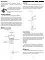
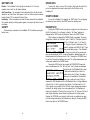
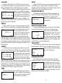
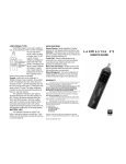
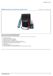
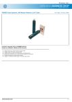
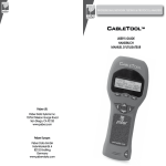
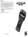
WARRANTY
Psiber Data Systems Inc. warrants that the product shall be free from defects in parts or workmanship for
a period of 12 months from the date of purchase if used in accordance with Psiber Data Systems Inc. operating
specifications.
THIS IS THE ONLY WARRANTY MADE BY Psiber Data Systems Inc. AND IS EXPRESSLY MADE IN
LIEU OF ALL OTHER WARRANTIES EXPRESSED OR IMPLIED, INCLUDING BUT NOT LIMITED TO ANY
IMPLIED WARRANTIES OF MERCHANTABILITY OR FITNESS FOR ANY PARTICULAR PURPOSE.
Should any parts or workmanship prove defective, Psiber Data Systems Inc. will repair or replace at
Psiber Data Systems’ option, at no cost to the Buyer except for shipping costs from the Buyer’s location to Psiber
Data Systems Inc. This is Buyer’s SOLE AND EXCLUSIVE REMEDY under this Agreement. This warranty does
not apply to products which have been subject to neglect, accident or improper use, or to units which have
been altered or repaired by other than an authorized repair facility.
Return of Equipment - To return a product to Psiber Data Systems Inc., first obtain a Return
Authorization number from our Customer Service by calling 619-287-9970. The RA# must be clearly marked on
the shipping label, or the package will not be accepted by Psiber Data Systems Inc. See sample label below.
To: Psiber Data Sytems Inc.
7075-K Mission Gorge Road
San Diego, CA 92120
RA# XXXXXXXX
LanMaster, psiber and the Psiber logo are trademarks of Psiber Data Systems Inc.
Copyright 2006 Psiber Data Systems Inc. All rights reserved.
P/N 1005-0350-0001 Rev. A
-7-
LANMASTER 35
TM
POWER AND LINK TESTER
USER GUIDE
BOX CONTENTS
• LanMaster 35 Power and Link Tester • Carrying Case • User Guide
• Four AA Alkaline Batteries • CableTracker 15 Tone Tracing Probe (Optional)
BATTERY
The LanMaster 35 operates on four AA alkaline
batteries. Remove the battery cover at the back of the
unit and insert the batteries with the orientation as
shown. Battery polarity is marked inside the battery well
for reference.
CABLETRACKER 15 TONE PROBE (OPTIONAL)
OVERVIEW
The CableTracker Model 15 Probe identifies cables and terminations by
detecting a trace tone signal transmitted by the LanMaster 35. When the Probe is
near the correct cable pair or punchdown, it indicates detection by emitting an
audible signal with the same pattern that is selected on the LanMaster 35.
TECHNICAL OVERVIEW
The LanMaster 35 Power and Link Tester provides seven different test
capabilities: 1) tests network connections for IEEE 802.3af, Cisco pre-standard
and non standard types of power, 2) conducts a power test with an actual load to
verify the amount of power available, 3) measures Link Resistance, 4) identifies
speed and duplex modes for 10/100/1000baseTX Ethernet Links, 5) provides a
Port Identification function with selectable blink rates to locate which port on a hub
or switch that a wall outlet is connected, 6) measures the cable length (only when
the cable is not connected to active equipment), 7) transmits a tone signal that
allows the cable to be traced or a punchdown identified with the CableTracker 15
Tone Probe.
MECHANICAL FEATURES
CABLE TRACING
Connect the LanMaster 35 to the RJ-45 on a cable. Turn on the Model 15
Probe by pressing and holding the button. Place the probe tip near the cable or
termination to be identified and the Probe will emit an audible signal. The audible
signal is loudest when the Probe is near the correct cable or termination point. The
volume can be adjusted by rotating the thumbwheel located above the button. The
Power ”ON” indicator is illuminated when the unit is on and the battery has
adequate voltage.
BATTERY
The CableTracker Model 15 Probe operates on one 9 volt alkaline battery.
Remove the battery cover at the back of the unit, connect the battery to the
battery snap cable, insert the battery in the battery well and replace the battery
cover.
BATTERY LIFE
The Model 15 Probe will operate for approximately 16 hours on one 9 volt
alkaline battery. When the battery is below the level required for the Model 15 to
operate properly, the Power “ON” indicator will not illuminate.
-1-
-6-
BATTERY LIFE
OPERATION
Duration - The LanMaster 35 will typically provide about 5 to 6 hours of
operation from a set of four AA alkaline batteries.
Auto Power Down - The Lanmaster 35 will automatically turn off after the time
selected in the Power Down Setup screen or will run continuously until manually
turned off when “ON” is selected for Power Down.
Low Battery - When the batteries are below the level required for the LanMaster
35 to operate properly, a battery graphic appears in the upper right hand corner of
the display.
To test a hub, switch, router or NIC, connect a patch cable from the RJ-45
port on the equipment, patch panel or wall outlet to the RJ-45 jack on the
LanMaster 35.
SAFETY
Disconnect any connections to the LanMaster 35 RJ-45 before opening the
battery cover.
-5-
START SCREEN
Turn on the LanMaster 35 by pressing the “PWR” button. The unit displays
an information screen and then the START screen for selecting a test.
POWER TEST
Pressing the POWER function key begins a voltage scan of all wire pairs on
the RJ-45 connection. If no voltage(s) is found, a “No Power” message is
displayed and an EXIT function is provided to return to the START Screen.
When voltage(s) is detected the POWER display is presented. The power
configuration is shown as “End-Span” (pairs 1,2 and 3,6), “Mid-Span” (pairs 4,5
and 7,8) or “All-Span” (pairs 1,2 4,5 and 3,6
7,8). The type of power is displayed as “PoE
Standard” (complies with IEEE 802.3af), “Cisco”
(Cisco pre-standard power) or “Non Standard”.
The voltage and polarity of the powered wire
pairs are also displayed. NOTE: If power is detected on additional wire pairs, a
double headed arrow will appear next to “Pair”. Pressing the UP/DOWN cursor
key will scroll through the additional wire pairs. The voltage measurements are
continuously updated in the POWER screen.
Pressing the INFO function key presents the POWER INFO Screen and
starts a loaded power test. The “No Load” and “Load” voltages are displayed.
The load test for a PoE Standard Link is about
10 Watts and the load test for a Cisco PreStandard Link is about 5 Watts. (The loaded
power test is not available for Non-Standard
power types or when less than 40 Volts is
measured for PoE Standard and Cisco Pre-Standard Links.) A voltage difference
of about 0.5 to 1.0 Volts is typical for short cables (1 to 25 feet) and 2.0 to 3.0
Volts is typical for long cables (200 to 300 feet). Larger voltage drops indicate a
problem in the cabling system or an under powered port. Link Resistance is
shown and is typically 0.5 Ohms for the port plus 2.0 to 2.5 Ohms per 100 feet of
cable. Higher resistance values indicate a problem with the cabling system.
Pressing the UP/DOWN cursor key will scroll through any additional wire pairs
that have voltage and display Link Resistance for each pair. Pressing the INFO
function key returns to the POWER Screen.
-2-
LINK TEST
SETUP
Pressing the LINK function key in the START screen begins a scan of the
RJ-45 connection for Link signals. If no Link signals are found, a “No Link Found”
message is displayed and EXIT and LENGTH function keys are provided.
When Link signals are detected, the LanMaster 35 displays the connection as
a LAN, NIC or an Auto MDI-X port; the speed
and duplex capabilites of the Link Partner. When
the Link is established, the EXIT, SETUP and
PORT ID function keys are displayed. Note: If a
Link Partner is not set to Auto-negotiate, the
duplex mode is unknown (shown as “UN” in the LINK screen). This is due to the
type of Link signals used in fixed modes.
Pressing the SETUP function key in any screen presents the Setup Screen.
The Up/Down cursor key is used to display: 1) Power Down Time Setup
2) Detection Level Setup 3) Units Setup and 4) Link Search Time Setup. Press the
SELECT function key to enter the displayed setup screen.
PORT ID
Pressing the PORT ID function key in the Link Screen presents the Port ID
Screen. As soon as this screen appears, the LanMaster 35 begins transmitting a
pattern of Link signals that will cause the hub,
switch or NIC Link LED to blink or stay on
continuously. This will identify the specific port a
wall outlet or PC is connected. Hubs and
switches from various manufacturers have
different specifications for the time it takes for Link signals to turn the Link LED on
and off. The LanMaster 35 has four different blink rates and a continuous mode that
can be selected by pressing the Up/Down cursor key. An initial test directly at the
hub or switch will determine the best blink rate setting before conducting a Port ID
test at a wall outlet.
LENGTH
The LENGTH function is only available when the LINK Test shows a “No
Link Found” condition. Pressing the LENGTH function key presents the LENGTH
Screen. Length is measured on pairs 1,2 and 3,6
with a minimum length of 6 feet (2 meters) and a
maximum length of 330 feet (100 meters). The
lengths of the two cable pairs may be slightly
different depending on how the pairs are twisted
together in the cable. The length measurement is to the nearest open or short in the
cable run. Typically this is an open at the end of the cable (disconnected RJ-45 or
unterminated cable). The LENGTH function should be used to identify cable faults
and provide the approximate location. The TONE function can then be used with
the CableTracker 15 Tone Probe to pinpoint the fault location.
TONE
Pressing the TONE function key in the START Screen presents the Tone
Screen and the LanMaster 35 begins transmitting
one of four tone patterns. Pressing the Up/Down
cursor key changes the tone pattern.
-3-
POWER DOWN SETUP
The LanMaster 35 will automatically turn off after the time selected in the
Power Down Setup screen. Settings available are five minutes, fifteen minutes,
thirty minutes and on (must be turned off
manually). Press the SAVE function key to store
the selected setting.
DETECTION LEVEL SETUP
The minimum voltage Detection level for the Power Test for PoE Standard
and Cisco Pre-Standard power is fixed at 40 Volts. The minimum voltage
Detection level for the Power Test for NonStandard power can be set from 12.5 Volts to 24
Volts (the default is 18 Volts). This allows the
user to test for other types of power that may be
on a connection such as some types of PBXs.
Pressing the Up/Down cursor key changes the level in 0.5V increments. Press
the SAVE function key to store the selected setting.
UNITS SETUP
The Units Setup Screen is used to select the units used when displaying the
length measurement in the Length screen. The Up/Down cursor key is used to
select Feet or Meters. Press the Save function
key to store the selected units.
LINK SEARCH SETUP
The Link Search setup screen is used to set the length of time that the
LanMaster 35 will monitor a wire pair for Link signals. The available settings are
Normal (default setting of about 2.5 seconds)
and Long (about 5 seconds). Use the Up/Down
cursor key to select the setting. Some switches,
especially if configured for VoIP, require a longer
time to complete Link negotiations and the Long
setting will provide more consistent Link detection.
-4-