1
PROFESSIONAL NETWORK TESTING & PROTOCOL ANALYSIS
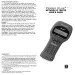
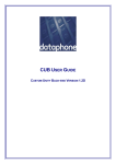
CableMaster 450
Voice, Data & Video Tester with
Length Measurement
User Manual
▪▪Tests Voice (6 wire), Data (8 wire)
and Video (coax)
▪▪Easy to read, extra large 7-segment
LCD screen with large icons
▪▪Tone generation over voice, data and
video cables, with 4 different tones
▪▪Measures length of entire cable and
individual wire pairs
▪▪RJ (Voice & Data) master remote
stores in bottom of case
▪▪Maps 19 locations at one time
▪▪Tests and indicates pins with shorts,
opens, reversals, miswires and split
pairs
▪▪Displays “Pass” icon for correctly
wired T568A/B and crossover/uplink
▪▪Displays “Pass” icon for correctly
wired 6-pin telephone plus “Rev” for
reverse-pinned
▪▪Low power consumption for long
battery life
▪▪Auto power-off
Psiber Data
www.psiberdata.com
CableMaster 450
Voice, Data & Video Tester with Length Measurement
User Manual
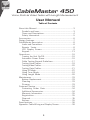
Table of Contents
About this Manual...................................................................3
Symbols and Icons..............................................................3
Terms and Descriptions......................................................4
Safety Information..............................................................5
Accessories......................................................................6
Design Features.......................................................................7
CableMaster Description...................................................8
Jacks and Connectors.........................................................8
Remote Tester...................................................................8
LCD Display Screen..........................................................9
Keypad.......................................................................13
Operations.....................................................................16
Turning the Unit On/Off...................................................16
Automatic Power Down...................................................16
Cable Testing General Guidelines....................................17
Testing Voice Cables.........................................................18
Testing Video Cables.........................................................20
Testing Data Cables.........................................................21
Using ID Mode..................................................................22
Using Tone Mode.............................................................24
Using Length Mode..........................................................26
Maintenance. ................................................................33
Battery Replacement........................................................33
Cleaning.......................................................................33
Storage....................................................................33
Customer Service...................................................................34
Contacting Psiber Data..................................................34
Additional Accessories.....................................................34
Warranty Information.......................................................35
Registration...............................................................35
Disposal......................................................................35
Returns........................................................................35
Specifications....................................................................36
Appendix: Cable Wiring and Display Screen.........................38
2
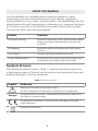
ABOUT THIS MANUAL
The CableMaster is a handheld device used by contractors, repair
technicians, and other authorized users to test, identify, and detect
potential faults in voice, video, and data cables. The CableMaster has the
added feature of length measurement, allowing you to measure the length
of a cable as a whole or by individual wire pairs located within a cable.
The test unit offers the following features:
Feature
Function
Continuity Testing
Discerns if the voice, data, and/or video cables
being tested have been wired correctly with
no faults.
ID Mapping
Identifies cables and determines their exact
location.
Tone Mode
Verifies cable wiring paths by sound.
Length Measurement
Determines the length of an entire cable and/
or individual wire pairs within the cable.
Symbols & Icons
The following symbols, listed in Table 1, used throughout the manual or
in the display screen of the test unit to help you avoid personal injury and
potential damage to the test equipment.
Table 1. Symbols and Icons
Symbol
!
Voltage!
Definition
Warning: Potential for personal injury
Caution: Potential for damage or destruction to equipment.
Voltage detection symbol. Immediately disconnect cables from
the main or remote tester.
Conformité Européenne. Conforms with European Economic
Area directives.
Disposal information
3
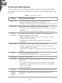
Terms and Descriptions
Table 2 defines the terms used throughout the document and provides
information to assist you with proper operation and understanding of the
test unit.
Table 2. Terms and Descriptions
Terms
Description and Uses
Video cable
Coax cable with a single pair (2 pin) wiring system
▪▪The pins are paired in order of continuity
▪▪Test this cable using the F-Connector on the main test unit
Data cable
Data cables with a 4 pair (8 pin) wiring system
▪▪Pin pairs are not wired by continuity, but follow a cabling
standard
▪▪Test this cable using the RJ45 adaptor on main test unit
Cabling
Standards
Standard wiring design of a cable. The pairing of wires
differs according to cable type.
▪▪Many standards adopt a wire coloring system to help
ensure proper pin pairing
▪▪Common data cable wiring standards are known as
T568A/B
Voice cable
Phone cable with a 3 pair (6 pin) wiring system
▪▪The pins are paired by continuity, except in the case of a
reverse pinned voice cable
▪▪Use the RJ11 adaptor on the main test unit to test a voice
cable
Pins
F-Connector
RJ Jack
Individual wires within a cable
▪▪Two pins paired together are known as pin pairs
Jack for a coax cable
Connector for a voice or data cable. RJ stands for Registered Jack.
▪▪The connector can be located on the tester itself. When
mounted on a wall, the RJ Jack is known as a wall port.
▪▪RJ11 is voice jack
▪▪RJ45 is data jack
RJ Plug
▪▪Cable end that is inserted into a wall port or the test unit
Length
Constant
Value
The amount of capacitance in picofarads (pF) per unit
distance.
4
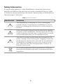
Safety Information
To ensure safe operation of the CableMaster, follow the instructions
carefully and observe the warning and caution messages listed in Table
3. Failure to observe warnings can result in severe injury or death and can
cause damage to the tester.
Table 3. Safety Information
Notification
Definition
!
The CableMaster is designed for use on unenergized
cabling systems. Connecting the CableMaster to live AC
power may damage the unit and pose a safety hazard for
the user.
!
Poorly terminated RJ plugs have the potential to damage
the jacks on the CableMaster. Visually inspect an RJ plug
before inserting it into the main or remote tester to ensure
you are placing the plug into the appropriate jack.
!
The cable’s contacts should always be recessed into the
plastic housing of the receiving jack. Plugging a 6-position
phone plug into the 8-position data jack on the tester has
the potential to damage the outer-most contacts of the
jack. Insert the cable into the appropriate connector on
remote or main tester.
Do not place equipment and its accessories in the trash.
Items must be properly disposed in accordance with local
regulations
5
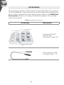
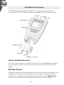
ACCESSORIES
The accessories listed in Table 4 below are provided with your purchase
of the CableMaster. These accessories must be used when operating the
unit in order to properly test and identify cables. Refer to the Additional
Accessories section for a listing of additional products that can help
make testing easier.
Table 4. CableMaster Accessories
Accessory
Description
No. 1 - 5 Network Remotes
{
No. 1 - 5 Coax Remotes
{
1-5 Network/Coax ID
Remotes with
F-Connector Coupler, F81
F-Connector Coupler
Cable assembly, RJ45
to Alligator Clips – 12”
6
DESIGN FEATURES
▪▪Easy to operate
▪▪Extra large seven-segment LCD screen with icons that clearly display
test results
▪▪Tests data (8-wire), voice (6-wire) and video (2-wire) cabling systems
▪▪RJ (Voice & Data) test remote stores in bottom of case plus a video ID
remote is included
▪▪Measures length of entire cable and individual wire pairs
▪▪Displays length reading in feet or meters
▪▪Wire mapping remotes for mapping cable runs to wall outlets accompany the CableMaster
▪▪Cable test results displayed in wire map format with connector pin
numbers
▪▪Tests and indicates pins with shorts, opens, reversals, miswires and
split pairs
▪▪Displays “Pass” icon for correctly wired T568A/B data cables
▪▪Shows “X-over” for correctly wired cross-over (uplink) data cables and
displays “Rev” for correctly wired reverse-pinned voice cables
▪▪Tone generator has a selectable tone cadence which is applied to
selected pins or pin pairs
▪▪Conserves power and supports long battery life with Auto-off feature
and battery low icon
▪▪Video and data cables can be connected to the tester at the same
time to improve testing efficiency
▪▪Patch cables may be tested without detaching the remote from the
main tester
7
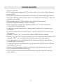
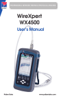
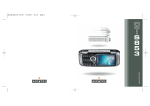
CableMaster Description
The CableMaster, illustrated in Figure 1, has four main parts: the
connectors, the LCD display screen, the keypad, and the remote tester.
RJ11 Jack
F-connector
RJ45 Jack
LCD Display Screen
Keypad
Remote Tester
RJ11 Jack
RJ45 Jack
Figure 1. CableMaster
Jacks and Connectors
The main unit connectors located at the top of the CableMaster include
two RJ Jacks for data and voice cables and one F-Connector for video
cables.
Remote Tester
The remote tester can be detached from the main unit to test cables over
a distance. The remote test unit has two RJ Jacks for data and voice
cables and is integral to the testing process. Refer to the Operations
section of the manual for detailed instructions on cable testing.
8
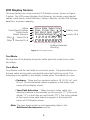
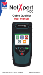
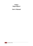
LCD Display Screen
The main tester has a high contrast LCD display screen, shown in Figure
2 below. The LCD screen displays the following: test mode, pass/special
cables, cable faults, shield indicator, battery capacity, locator ID#, voltage
detection, and wire mapping.
Mode
Pass/Special Cables
Cable Faults
Shield Indicator
Tester Pin #
Wire
Map Remote Pin #
{
Voice Data Video Tone
Pass X-over Rev
Fail Short Split Open
Shielded Voltage! ID
10
9
Battery Low
Locator ID #
12 3 4 5 6 7 8
1
8
Voltage Detected
Warning
Figure 2. LCD Display Screen
Test Mode
The top line of the display shows the cable type test mode (voice, data,
and video).
Tone Mode
Tone Mode must be used with a tone tracer probe. The probe allows you
to trace cable wiring paths and identify potential faults by sound. The
following icons appear in the display screen when Tone Mode is in use:
▪▪Cadence - There are four cadence options: HI, LO, Hi-Lo1, and
Hi-Lo2. The last selected cadence appears in the lower right
corner of the display screen.
▪▪Tone Path Selection – When tracing a video cable, the
selected cadence is transmitted on the coax pin (“P”), the coax
shield (“S”), or both the pin and shield (“PS”). The icons related
to the current tone path selection appear in the lower left
corner of LCD display screen.
Note: The tone tracer probe is sold separately (refer to the Additional Accessories section)
9
Length Mode
When the LENGTH/TONE button is pressed, the measured cable length
(in units of feet or meters) appears in the lower right corner of the LCD
display screen and the “L” icon appears above pins 7 and 8 in the Wire
Map. The following values and icons display in the screen when measuring cable length:
▪▪Edit Capacitance – When adjusting the length constant value for a
cable, the “Edit Cap” icon appears in the bottom of the screen. An “E”
icon displays above pins 7 and 8 in the Wire Map to indicate you are
in Edit Mode.
▪▪Length Constant Value – A value, measured in picofarads (pF) per
foot or meter appears in the bottom of the LCD display screen. This
value corresponds to the selected cable type and can be adjusted at
any time. When viewing the length constant value for a cable type,
the “C” icon displays above pins 7 and 8.
Pass/Special Cables
The second row of the display screen corresponds to the wiring structure of
the cable being tested. The Tri Tester™ displays the following three icons:
▪▪Pass – The “Pass” icon appears if the cable has a properly wired
4-pair T568A/B data cable, a 3-pair one-to-one wired voice cable, or a
video cable with no faults.
▪▪X-over – This icon displays if a properly wired cross-over (uplink)
data cable is recognized. A crossover cable is a data cable with
the 1-2 pair wired to the 3-6 pair. This allows an Ethernet NIC card
without MDIX capability to communicate by wiring the transmit end
of the cable to the receiver on the opposite end of the cable.
▪▪Rev – The “Rev” icon is displayed when the cable is a properly
wired reverse-pinned voice cable. A reverse-pinned voice cable
has all wires on one cable connector ordered by continuity and the
connector on the opposite end of the cable has the pins located in a
reversed order. Pin 1 connects to Pin 6 on the opposite connector; Pin
2 connects to Pin 5 and so on.
Cable Faults
There are four possible error conditions on the cable: Fail, Short, Split,
and Open. Cable faults appear in the third row of the LCD screen. The
faults are described in Table 5 below. Refer to the Appendix for a visual
representation of cable faults and how they appear in the Wire Map.
10
Table 5. Cable Faults
Cable Fault
Description
Fail
A “Fail” error occurs when a cable’s wire connections do
not follow cabling standards.
▪▪This icon will illuminate when any cable fault is detected
▪▪Any miswired pin pairs will flash in the Wire Map
Open
An “Open” error means a wire connection within the cable
is not continuous through the length of the cable.
▪▪The pin pairs with errors will flash in the Tester Pin #
field of the Wire Map and will be blank in the Remote
Pin # field
Short
The “Short” icon appears when two or more wires within
a cable are electrically connected. This is also known as a
short circuit.
▪▪A dash (-) will appear in the Remote Pin # field to indicate
the shorted pin pairs
▪▪This dash will appear directly below the flashing pairs in
the Tester Pin # field
Split
A split, also known as an AC signal fault, occurs when
wires are not twisted together according to their cabling
standard.
▪▪This miswire commonly occurs with pins 3, 4, 5, and 6 in
a data cable
▪▪The pin pairs experiencing the split will flash in the
Remote Pin # fields of the wiring map
Note: Open and Short errors take precedence over miswires and the
appropriate icon(s) will appear in the display screen.
If the pairs displayed in the Wire Map are flashing, the cable
has a problem (split, open, short, or fail). If the pairs are not
flashing, the cable is wired properly and a “Pass” icon will
appear.
The accuracy of the CableMaster is limited to identifying
the pin pairs with errors. It cannot identify the individual pin
experiencing the error.
11
Shield Indicator
The “Shielded” icon, appearing in the fourth line of the LCD screen,
illuminates when a shielded data cable is properly wired at both ends. The
icon flashes if the shield is shorted to a pin in the cable. The shorted pins
display in the Wire Map and the “Short” indicator appears.
Wire Map: Tester Pin #
The top line in the Wire Map shows the pin numbers of the cables
connected to the main tester. If a cable fault is detected, the pin pairs
experiencing the error will flash.
Wire Map: Remote Pin #
The bottom line of the Wire Map corresponds to cables connected to the
remote tester. The Remote Pin # field will show if the connected cables
have errors (short, open, fail, and split). The appearance of dash lines
indicates shorted pins. No number displayed in the Remote Pin Number
line indicates Open pins. Pin pairs will flash if they are split.
Battery Low
The battery low symbol illuminates when the battery is nearing depletion.
The symbol flashes when the battery needs to be replaced.
Note: Results may be unreliable at this point so the battery should be
replaced.
Location ID
The “ID” symbol, located in the third line of the LCD screen, appears when
the CableMaster is in Video, Data, or ID Mode. When using the wire
mapping remotes, the “ID” icon will turn on and the remote ID number will
display to its right. The ID number is not displayed if an error occurs, such
as “Open” or “Short”.
Voltage Detected Warning
If voltage is detected on any of the cable connectors, the “Voltage!” icon
flashes. A check for voltage is performed before each test and if found,
no test is run. If the icon appears, the tester should be disconnected immediately from the source of the voltage. The tester automatically powers
down in 90 seconds if the detected voltage is not removed.
12
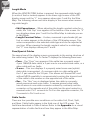
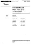
Keypad
The CableMaster is equipped with five buttons, illustrated in Figure 3.
Some buttons have more than one function. The functions are explained in
Table 6. For each cable test, results are displayed in the Wire Map of the
LCD display screen.
Voice Mode
Video Mode
Length Measurement/
Tone Generation Mode
Data Mode
On/Off and ID Mode
Figure 3. Keypad
13
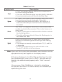
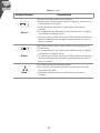
Table 6. Keypad
Keypad Button
Voice
Video
Data
Description
The Voice button tests voice cables.
▪▪Each press of the button causes one test to be run on
the 6-position RJ jack
▪▪Hold the button down to start/stop continuous
testing
▪▪In Length Mode, the blue arrow allows you to adjust
the length constant value
▪▪A short press of the Voice and Video buttons simultaneously changes the length measurement unit from
feet to meters.
The Video button tests coax cables terminating at an
F-Connector.
▪▪In Length Mode, the blue arrow allows you to adjust
the length constant value.
▪▪A short press of the Voice and Video buttons simultaneously changes the length measurement unit from
feet to meters.
The Data button tests data cables.
▪▪Each press of the data button runs one test on the
8-position RJ jack
▪▪Hold the button down to start/stop continuous
testing
14
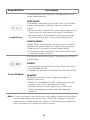
Keypad Button
Description
This button has two functions: Tone generation and
length measurement.
Length/Tone
TONE MODE
Tone Mode, indicated by a musical note, is used with
a tone tracer probe to identify faults in cables via
sound.
▪▪When the unit is turned Off, press and hold down the
Tone button for two seconds to enter Tone Mode
▪▪An audio tone is transmitted from the unit through
the selected wire pairs of the cable being tested
LENGTH MODE
Length Mode, indicated by a double arrow, is used to
measure the entire length of a cable and its pin pairs.
▪▪One press of the button enters Length Mode
▪▪A long press (two seconds) of the button allows you
to edit the length constant
This button has two functions: Turning the unit On/Off
and ID Mode.
POWER
▪▪In any test mode, one press of the O/ID button turns
the CableMaster Off
▪▪Subsequent presses of the button turn the unit On/Off
Power/ID Mode
ID MODE
ID Mode is used with wire mapping remotes to
identify cable runs.
▪▪When the CableMaster is Off, one press of this button turns the unit on and begins ID mode
▪▪ID Mode scans all cable types (voice, video, and
data) and displays any detected wire mapping
remotes
Note: To run a continuous test on data or voice cables, press and hold down
the corresponding mode button until “LOOP ON” appears. Tests will
execute until another cable test mode or O/ID buttons are pressed or
after 5 minutes of no change in the test result.
15
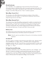
OPERATIONS
To ensure safe operation of the CableMaster, follow the instructions
carefully and pay attention to the warning and caution symbols. Failure
to observe warnings can result in severe injury or death and can cause
damage to the tester.
Turning the Unit On/Off
Turn Unit On
▪▪Press the desired cable type button (voice, video, data, tone or ID) to
start testing in that mode immediately.
Turn Unit Off
▪▪Press the O/ID button to power down the tester. The display screen
will go blank
.
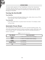
Automatic Power Down
The CableMaster automatically turns off to conserve battery power. The
automatic power down feature varies according to which cable test mode
is in use (see Table 7). The power down timer is restarted whenever a
button is pressed.
Table 7. Automatic Power Down
Test Mode
Time (seconds)
Voice
▪▪18 sec. (5 minutes when looping)
Data
▪▪18 sec. (5 minutes when looping)
Video
▪▪ 5 minutes
Length/Tone
▪▪60 minutes
ID
▪▪ 5 minutes
16
Cable Testing General Guidelines
The CableMaster tests video, data, and voice cables to detect potential
faults, measures cable length, shows a cable’s wire pairing, and examines
the physical properties of a cable.
Important Points to Note
▪▪The RJ jacks for data and phone cables share internal connections
within the tester. Only one RJ cable can be connected at a time for
accurate cable test results.
▪▪An RJ cable and a coax cable may be connected at the same time. In ID
mode, all connectors on the Tester may be connected at the same time.
▪▪To easily toggle between cable test modes, press the desired cable
type button.
Important Points to Note
!
!
!
The CableMaster is designed for use on unenergized cabling
systems. Connecting the CableMaster to live AC power may
damage the unit and pose a safety hazard for the user.
Poorly terminated RJ plugs, the head of a cable, have the
potential to damage the jacks on the CableMaster. Visually
inspect an RJ plug before inserting it into the tester to ensure
you are inserting the plug into the appropriate jack of the
remote-end or tester-end of the unit (ex. data cable plug fits
into data jack on the unit).
The cable’s contacts should always be recessed into the plastic
housing of the receiving jack. Plugging a 6-position phone plug
into the 8-position data jack on the tester has the potential to
damage the outer-most contacts of the jack. Insert the cable
into the appropriate connector on the remote end or tester end
of the unit.
17
Testing Voice Cables
Testing a voice cable is a 2-end test where one end is connected to the
main tester and the other end is connected to the remote tester.
!
Plug the cable into the appropriate jacks on the main tester and
remote tester. Failure to do so can damage the connectors.
1. Insert one end of the cable into the RJ11 jack on the main tester.
2. Place the other end of the cable into the RJ Jack on the remote
tester.
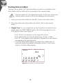
3. Single Test: To run a single test on the 6-position connected voice
cable, press the VOICE MODE button. The following appears in the
LCD display screen (see Figure 4):
▪▪The “Voice” icon appears in the upper left corner.
▪▪The cable wiring structure displays (Pass, X-over, or Rev).
▪▪The “ID” icon appears with remote #1 displayed as the cable is
connected to the remote tester.
▪▪The Wire Map fields update to indicate any cable faults. A
perfectly wired voice cable will display all pins (1-6) in both
fields of the Wire Map display.
Voice Data Video Tone
Pass X-over Rev
Fail Short Split Open
Shielded Voltage! ID
10
9
12 3 4 5 6 7 8
1
8
Figure 4. Voice Mode Test with Rev Cable
18
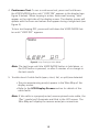
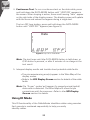
4. Continuous Test: To run a continuous test, press and hold down
the VOICE MODE button until “LOOP ON” appears in the display (see
Figure 5 below). When looping is active, three small moving “bars”
appear on the right side of the display screen. The display screen will
update with the icons and values that appear during a single test (see
Figure 4).
To turn test looping OFF, press and hold down the VOICE MODE button until “LOOP OFF” appears.
Voice Data Video Tone
Pass X-over Rev
Fail Short Split Open
Shielded Voltage! ID
10
9
12 3 4 5 6 7 8
1
8
Figure 5. Loop Testing in Voice Mode
Note: The test loops until the VOICE MODE button is held down, or
the O/ID button is pressed, or after 5 minutes of no change in
the test results
5. Trouble-shoot if cable faults (open, short, fail, or split) are detected.
▪▪The pins experiencing error(s) appear in the Wire Map of the
display screen.
▪▪Refer to the LCD Display Screen section for details of the
cable faults.
Note: If the cable is a properly wired, reverse-pinned voice cable, the
“Rev” symbol will illuminate and blink in the LCD screen. The
Wire Map will display the reverse wired pin connections.
19
Testing Video Cables
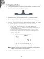
1. Connect the provided F-Connector coupler to the F-Connector at the
top of the main tester (see Figure 6 below).
Figure 6. F-Connector on Main Tester
2. Screw one end of the video cable into the F-Connector coupler.
3. Secure a Coax remote to the opposite end of the video cable.
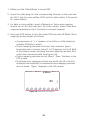
4. Press the VIDEO MODE button to start continuous testing. The following updates appear in the LCD display screen (see Figure 7):
▪▪The “Video” icon illuminates in the upper right corner.
▪▪A progression of “o’s” appear on the bottom of the display to
indicate active testing.
▪▪The cable wiring structure displays (Pass, X-over, or Rev).
▪▪The “ID” icon appears with the Coax wire mapping remote
number to its right.
Voice Data Video Tone
Pass X-over Rev
Fail Short Split Open
Shielded Voltage! ID
10
9
12 3 4 5 6 7 8
1
8
Figure 7. Loop Testing in Video Mode
Note: The tests run until the O/ID button is pressed or when 5 minutes
elapses with no change in the test results.
5. Trouble-shoot if cable faults (open or short) are detected.
20
Testing Data Cables
Testing a data cable is a 2-end test where one end is connected to the
main tester and the other end is connected to the remote tester.
1. Plug one end of the data cable into the RJ45 jack on the main tester.
!
Visually inspect the tester to make sure you are inserting the
cable into the appropriate jack.
2. Insert the opposite end of the cable into the RJ45 jack on the remote
tester.
3. Single Test. To run a single test, press the DATA MODE button. The
following appears in the display screen (see Figure 8):
▪▪The “Data” icon appears at the top of the screen.
▪▪The cable wiring structure displays (Pass, X-over, or Rev).
▪▪The “ID” icon appears with remote #1 displayed as the cable is
connected to the remote tester.
▪▪The Wire Map fields update to indicate any cable faults. A
perfectly wired data cable will display all pins (1-8) in both
fields of the Wire Map display.
Voice Data Video Tone
Pass X-over Rev
Fail Short Split Open
Shielded Voltage! ID
10
9
12 3 4 5 6 7 8
1
8
Figure 8. Data Mode Test
21
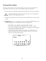
4. Continuous Test. To run a continuous test on the data cable, press
and hold down the DATA MODE button until “LOOP ON” appears in
the screen. When looping is active, three small moving “bars” appear
on the right side of the display screen. The display screen will update
with the icons and values that appear during a single test.
The turn OFF loop testing, press and hold down the DATA MODE
button until “LOOP OFF” appears (see Figure 9).
Voice Data Video Tone
Pass X-over Rev
Fail Short Split Open
Shielded Voltage! ID
10
9
12 3 4 5 6 7 8
1
8
Figure 9. Loop Off in Data Mode
Note: The test loops until the DATA MODE button is held down, or
O/ID button is pressed, or after 5 minutes of no change in the
test result.
5. Interpret display results and trouble-shoot potential cable faults.
▪▪The pins experiencing error(s) appear in the Wire Map of the
display screen.
▪▪Refer to the LCD Display Screen section for details of the cable
faults.
Note:The “X-over” symbol will appear if a properly wired (uplink)
data cable is detected. The Wire Map will show the pin
connections with the crossover. Refer to the LCD Display
Screen section for details
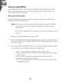
Using ID Mode
This ID functionality of the CableMaster identifies cables using remotes.
Each remote is numbered sequentially to help you easily
identify cables.
22
1. Make sure the CableMaster is turned OFF.
2. Insert the cable plug into the corresponding receiver on the main tester (RJ11 jack for voice cables, RJ45 jack for data cables, F-Connector
for video cables).
3. For data or voice cables, insert a Network or Voice wire mapping
remote into an RJ Jack wall port. For video cables, attach Coax wire
mapping remote(s) to the F-Connector coax wall receiver.
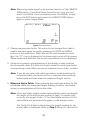
4. Press the O/ID button to turn the tester ON and enter ID Mode. Wire
mapping results display as follows
▪▪A progression of “o’s” appear on the bottom of the display to
indicate ID Mode is active.
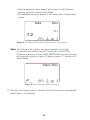
▪▪If wire mapping remotes are found, the connector type illuminates and a numeric value (1 to 19) appears in the ID field
of the display screen showing the wire mapping remotes that
match the connected cable (see Figure 10).
▪▪If wire mapping remotes are not found, “Open” displays in the
LCD screen.
▪▪If multiple wire mapping remotes are found, the ID or fault is
displayed automatically in sequenceIf wire mapping remotes
are not found, “Open” displays in the LCD screen.
Voice Data Video Tone
Pass X-over Rev
Fail Short Split Open
Shielded Voltage! ID
10
9
12 3 4 5 6 7 8
1
8
Figure 10. Detected Coax Remote
23
Using Tone Mode
Tone Mode is used to trace cable runs and locate faults by sound.
Selection of this mode emits a cadence from the main tester through
the connected cable. The tone is detected by a tone tracer probe (sold
separately. Refer to the Additional Accessories section).
Note: It may be impossible to differentiate between the tone
generated from the test pair and the sound emitted by
neighboring wiring pairs within the cable.
1. Connect one end of the cable to the main tester. The remote tester is
not used.
2. With the unit turned OFF, press and hold down the LENGTH/TONE
button for two seconds to enter Tone Mode.
3. To select a tone cadence, press the LENGTH/TONE button repeatedly
to step through the 4 cadence options: HI, LO, Hi-Lo1, and Hi-Lo2.
Stop when you reach the option you want.
The option you select determines the cadence sent from the main
tester, through the cable, and picked up by the tone tracer probe.
Note: If you do not adjust the cadence, the main tester will default to
the last selected cadence.
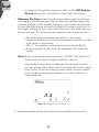
4. Press the appropriate cable type button (voice, video, or data) to
select a cable for the tone signal.
5. Press the cable type button again to select different combinations
of pins to carry the tone signal. Each press of the cable type button
steps you through the cable’s wire pairs. The selected pin pair appears in the Wire Map. Figure 11 shows pin pairs 1 and 2 selected for
testing a data cable.
The following appears in the LCD display screen:
▪▪The cable type icon appears at the top of the screen.
▪▪The “Tone” icon displays in the upper right corner of the screen.
24
▪▪Three progression bars appear above pins 7 and 8 demonstrating you are in active Tone Mode.
▪▪The selected pin pairs appear in the wire map of the display
screen.
Voice Data Video Tone
Pass X-over Rev
Fail Short Split Open
Shielded Voltage! ID
10
9
12 3 4 5 6 7 8
1
8
Figure 11. Tone Mode with Data Cable Selected and Hi-Lo1 cadence
Note: For tracing video cables, you must choose a tone path
to transmit the cadence (pin (P), shield (S), or both (PS)).
Continuous presses of the VIDEO MODE buttons steps through
the tone path options. Figure 12 below shows “P” selection in
Video Mode.
Voice Data Video Tone
Pass X-over Rev
Fail Short Split Open
Shielded Voltage! ID
10
9
12 3 4 5 6 7 8
1
8
Figure 12. Video Cable Test with Pin Selected
6. Use the tone tracer probe to locate faults and track wire runs behind
walls, floors, and ceilings.
25
Using Length Mode
Length Mode is used to measure the length of entire cables and its pin
pairs and allows you to view and adjust the length constant value for
video, data, and voice cables.
Measure Cable Length
The CableMaster measures the entire length of a cable as well as the
length of individual wire pairs.
Note: Using coax or data remotes while measuring length will add
one to two feet to the length reading due to internal stray
capacitance.
If a cable’s capacitance is too large, dashes will display for the
length.
1. Make sure the CableMaster is turned OFF.
2. Insert the cable plug into the corresponding receiver on the main tester (RJ11 jack for voice cables, RJ45 jack for data cables, F-Connector
for video cables).
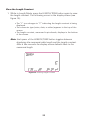
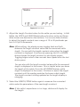
3. Press the LENGTH/TONE button to enter Length Mode. The following
icons appear in the display screen (see Figure 13).
▪▪An “L” icon appears in the right side of the screen.
▪▪Cable length in units of feet or meters displays in the bottom
of the screen.
▪▪The connector type last selected (voice, data, or video)
displays in the top of the screen.
▪▪An “o” symbol bounces in the lower left corner of the screen
to indicate activity.
26
Note: Measuring cable length is the primary function of the LENGTH/
TONE button. If you hold down the button too long, you will
enter Tone Mode. If you mistakenly enter Tone Mode, simply
press the O/ID button and select the LENGTH/TONE button
again to enter Length Mode. Voice Data Video Tone
Pass X-over Rev
Fail Short Split Open
Shielded Voltage! ID
10
9
12 3 4 5 6 7 8
1
8
Figure 13. Length Mode
4. Change measurement units. The units can be changed from feet to
meters and back again by quickly pressing the VOICE and VIDEO
buttons at the same time. When the unit of measurement is set to
feet, the “Ft” icon is displayed in the lower right corner of the screen.
When meters are selected, the unit of measurement is not displayed.
5. Verify the connector type appearing in the display screen matches
the connected cable. If it does not match, press the cable type button
corresponding to the cable you plan to measure (voice, video, or data).
Note: If you do not select the cable type button mode matching the
connected cable, the tester will try to measure the previously
tested cable and may skew the measured length results.
6. Measure Entire Cable: After selecting the cable type button for the
connected cable, the measured length reading shown in the display
screen is representative of the entire cable.
Note: Voice and Video length modes automatically select and display
the length of the first pin pair without a fault. For cables with
no faults, the length of pair 1-2 for Data Mode and pair 3-4 for
Voice Mode will automatically appear in the display screen
The Tester Pin # field is blank when the length reading for the
entire cable is displayed. Refer to Step 7 below for instructions
27
on stepping through the wire pairs. Refer to the LCD Display
Screen section for a description of the Tester Pin # field.
7. Measure Pin Pairs: Press the cable type button again to measure
the length of the first pin pair. The number(s) for the pair being measured will display in the screen (see Figure 14). Subsequent presses
of the cable type button will cycle through all the pairs and return to
the length reading for the entire cable when you have advanced past
the last pin pair. The following icons appear in the display screen:
▪▪The cable type icon appears at the top of the screen.
▪▪Length of pin pairs in units of feet or meters displays in lower
right corner of the screen.
▪▪The “L” icon displays indicating you are in Length Mode.
▪▪A bouncing ball activity indicator appears in the lower left
corner.
Note: If the selected cable pair is shorted, “SHORT” will display for
the shorted pair and the length readout is dashes.
The number of wire pairs is dependent on the type of cable
you are testing. Data cables have 4 wire pairs and voice cables
have 3 pairs. If you are testing a video cable, you will receive
only 1 length measurement reading as a video cable has a
single wire pair.
Figure 14. Length of Pin Paris 3 and 4
8. Interpret display results and trouble-shoot potential cable faults.
28
View the Length Constant
1. While in Length Mode, press the LENGTH/TONE button again to view
the length constant. The following occurs in the display screen (see
Figure 15):
▪▪The “L” icon changes to “C” indicating the length constant is being
displayed.
▪▪The connector type (voice, data, or video) appears in the top of the
screen.
▪▪The length constant, measured in picofarads, displays in the bottom
of the screen.
Note: Each press of the LENGTH/TONE button toggles between
displaying the measured cable length and the length constant.
After a few seconds the display screen defaults back to the
measured length.
Voice Data Video Tone
Pass X-over Rev
Fail Short Split Open
Shielded Voltage! ID
10
9
12 3 4 5 6 7 8
1
8
Figure 15. Viewing Length Constant
29
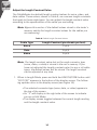
Adjust the Length Constant Value
The CableMaster has default length constant values for voice, video, and
data cables. These values, shown in Table 8, are common length constants
that apply to these cable types. You can adjust the length constant value
according to the specifications of the cable you are testing.
Note: Bypass this section if the default values stored in the tester’s
memory satisfy the length constant values for the cables you
are measuring.
Table 8. Default Length Constant Values
Cable Type
Length Constant (picofarads per foot)
Voice
17 pf/ft
Data
15 pf/ft
Video
15 pf/ft
Note: The length constant value last set for each connector type
(voice, video, or data) is stored in the unit’s memory. If you
have not adjusted the length constant value for any or all cable
types, the default values will be stored. The length constant
can be adjusted at any time.
1. When in Length Mode, press and hold the LENGTH/TONE button until
“EDIT CAP” appears in the bottom of the display screen. The following updates occur in the display screen (see Figure 16):
▪▪The selected connector type (voice, data, or video) appears in
the top of the screen.
▪▪An “E” will display in the right side of the screen to indicate
you are in Edit Mode.
▪▪The display screen toggles between the current length reading
and the length constant value.
30
Voice Data Video Tone
Pass X-over Rev
Fail Short Split Open
Shielded Voltage! ID
10
9
12 3 4 5 6 7 8
1
8
Figure 16. Edit Mode
2. Adjust the Length Constant value for the cable you are testing. In Edit
Mode, the VOICE and VIDEO Mode buttons function as Up and Down
(blue arrows are denoted on the buttons). You can use these buttons
to adjust the length constant over a range of 10 to 40 picofarads per
foot in 0.1pF/ft increments.
Note: While editing, the display screen toggles back and forth
between the length constant value and the measured cable
length. You can edit the length constant value when the length
constant is displayed. Continuously pressing the UP or DOWN
buttons keeps the length constant on the display screen.
Toggling begins when a few seconds have lapsed after the last
button press.
You can also edit the length constant value while the measured
length is displayed in the screen. This is helpful when you know
the length of the cable. Press the UP/DOWN buttons while
length is displayed in the screen. Continue to adjust the length
constant until the reading matches the known cable length. The length constant is being updated as the length display is
changing.
3. Select the LENGTH/TONE button again to measure the connected
cable under the parameters of the new length constant.
Note: If the cable’s capacitance is too large, dashes will display for
the length.
31
Changing the connector type or exiting Length Mode will store
the adjusted length constant in the unit’s memory for the next
test. Up to three length constants can be stored, one of each
connector type.
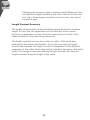
Length Constant Accuracy
The length constant refers to the electrical parameter used to measure
length, in this case, the capacitance of the cable per foot or meter.
Accuracy is dependent on how close the instrument can be set to the
cable constant for the cable being measured.
The length constant can vary from cable to cable, of the same type
produced by the same manufacturer. It can also vary over the length
of one cable because the length constant is dependent on the physical
properties of the cable, which may not be consistent throughout the entire
cable. The change in wire pair spacing through the cable can vary the
length constant along the length of the cable.
32
MAINTENANCE
Battery Replacement
1. Remove the single screw, located in the middle of the back of the
CableMaster, with a #1 Philips head screwdriver.
2. Take out the old battery and disconnect the battery cable.
3. Replace the old battery with an ANSI 1604A, 9 volt alkaline battery
(Energizer 522, Duracell MN1604). Reattach the cable to the new
battery and place the new battery into the battery compartment.
4. Return the battery door to the unit and turn the screw into place to
secure the battery door.
!
Do not over tighten the battery door. Doing so can damage the
test unit.
Cleaning
Use a damp, clean cloth to clean the tester.
!
Disconnect all cables from the CableMaster prior to cleaning.
Failing to do so can damage the unit and result in personal
injury.
Do not use abrasive, harsh cleaners, or solvents to clean the
CableMaster.
Storage
When the CableMaster is not in use, store it in a dry, protective case.
The battery should be removed if the tester is stored for a long period
of time.
Do not expose the CableMaster to high temperatures or humidity. When
stored in temperatures exceeding the limits listed in the Specifications
section, allow the CableMaster to return to the normal, recommended
operating conditions prior to use.
33
CUSTOMER SERVICE
Contacting Psiber Data
For technical information and support please contact
the Psiber Office in your country.
Psiber US: Psiber Data Sytems Inc. Phone: +1 (619) 287 99970,
e-mail: [email protected], www.psiber.com
Psiber Europe: Psiber Data GmbH, Phone: +49 (89) 8913 6060,
e-mail: [email protected], www.psiberdata.com,
Psiber Asia/Pazific: Psiber Data Pte. Ltd., Phone: +65-6569-6019,
e-mail: [email protected], www.psiberdata.com
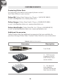
Additional Accessories
Table 9 below lists the additional accessories that are available for
purchase through Psiber Data. Contact Psiber Data for more information.
Table 9. Additional Accessories
Accessory
Description
Tone Probe
(1 – 19) Coax wire
mapping remotes
with 20 hole foam
remote holder
(1 – 19) Network
wire mapping
remotes with 20 hole
foam remote holder
34
Warranty
Psiber Data warrants that the product shall be free from defects in parts or workmanship for a
period of 12 months from the date of purchase if used in accordance with Psiber Data operating
specifications.
THIS IS THE ONLY WARRANTY MADE BY Psiber Data AND IS EXPRESSLY MADE IN LIEU
OF ALL OTHER WARRANTIES EXPRESSED OR IMPLIED, INCLUDING BUT NOT LIMITED TO
ANY IMPLIED WARRANTIES OF MERCHANTABILITY OR FITNESS FOR ANY PARTICULAR
PURPOSE.
Should any parts or workmanship prove defective, Psiber Data will repair or replace at Psiber Data’
option, at no cost to the Buyer except for shipping costs from the Buyer’s location to Psiber Data.
This is Buyer’s SOLE AND EXCLUSIVE REMEDY under this Agreement. This warranty does not
apply to products which have been subject to neglect, accident or improper use, or to units which
have been altered or repaired by other than an authorized repair facility.
For US-Customers:
Return of Equipment – To return a product to Psiber Data Systems Inc., first obtain a Return
Authorization number from our Customer Service by calling +1 619-287-9970. The RA# must be
clearly marked on the shipping label, or the package will not be accepted by Psiber Data Systems
Inc. See sample label below.
To: Psiber Data Sytems Inc.
7075-K Mission Gorge Road
San Diego, CA 92120
RA# XXXXXXXX
For European-Customers:
Return of Equipment – To return a product to Psiber Data GmbH, first obtain a Return Authorization
number from our Customer Service by calling +49-89-89136060. The RA# must be clearly marked
on the shipping label.
To: Psiber Data GmbH
Felix-Wankel-Str. 4
82152 Krailling
Germany
RA# XXXXXXXX
For ASIA/PACIFIC-Customer:
Return of Equipment - To return a product to Psiber Data Pte. Ltd., first obtain a Return
Authorization number from Our Customer Service by calling +65-6569-6019 or e-mail: asiasales@
psiber-data.com. The RA# must be clearly marked on
The shipping label.
To: Psiber Data Pte. Ltd.
3 Science Park Drive
#03-09 The Franklin
Singapore Science Park 1,
Singapore 118223
RA# XXXXXXXX
Copyright 2012 Psiber Data. All rights reserved. CableMaster, psiber and the Psiber logo are
trademarks of Psiber Data.
35
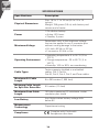
SPECIFICATIONS
Specifications
Description
Physical Dimensions
Size: 16.3 x 7.1 x 3.6 cm (6.4 x 2.8 x 1.4
inches)
Weight: 256 grams (9.0 oz) with battery and
remote-end of tester
Power
1 9V alkaline battery
▪▪Active: 425 hours
▪▪Standby: 4 years
Maximum Voltage
Parameters refer to the maximum voltage
that can be applied to any 2 connector pins
without causing damage to the tester.
▪▪RJ Jack: 66 Vdc or 55 Vac
▪▪F-connector: 50 Vdc or Vac
Operating Environment
▪▪Operating temperature: 0 to 50 °C (32 to
122 °F)
▪▪Storage temperature: -20 to 60 °C (-4 to
140 °F)
▪▪Humidity: 10% to 90%, non-condensing
Cable Types
Tester supports shielded or unshielded
cables, Cat-7, Cat-6x,
Cat-5E, Cat-5, Cat-4, Cat-3, and Coax cables.
Maximum RJ Cable
Length
0 to 305 meters (1,000 feet)
Minimum Cable Length
for Split Pair Detection
0.5 meters (1.5 feet)
Maximum Coax Cable
Length
100 ohms maximum DC resistance, center
conductor plus shield
Low Battery
Icon flashes when battery voltage falls
below 6V
Measurement
Technology
Capacitance testing
Complies with Conformité
Européenne directives.
Compliance
36
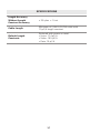
SPECIFICATIONS
Length Accuracy
Without Length
Constant Accuracy
± 3% plus ± 1 foot
Cable Length
Minimum of 2,000 ft CAT5E cable with
15 pF/ft length constant
Default Length
Constants
Restored with power on reset.
▪▪Voice: 17.4 pF/ft
▪▪Video: 16.5 pF/ft
▪▪Data: 15 pF/ft
37
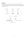
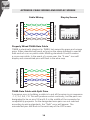
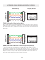
APPENDIX: CABLE WIRING AND DISPLAY SCREEN
Cable Wiring
Display Screen
1
2
3
4
5
6
7
8
Cable Wiring
Display S
1
2
3
4
5
6
7
8
Remote Tester Pins
CableMaster
Tri TesterTMPins
Pins
Cable Wiring
Voice Data VideoTone
Pass X-over Rev
Fail Short Split Open
ShieldedVoltage!ID
12 3 4 5 6 7 8
Properly
T568B is
T568A, b
and oran
will work
standard
run or pa
A and B c
In the eve
“X-over”
mismatch
wire map
Display S
T568A D
77
88
11
22
33
44
55
66
77
88
11
22
33
44
55
66
77
88
X
Remote
Tester
Remote
Tester
PinsPins
77
88
Remote
Tester
Pins
Remote
Tester
Pins
TM
CableMaster
Pins
Tri TesterTM
Pins
TM
Tri TesterTM
Pins
AProperly
commo
Properly11Wired T568A Data Cable 11
T568B
to putisa
22 swaps the green and orange isT568A,
T568B is 22electrically identical to T568A, but
1-2, 3-4,b
3
3
and
oran
3
3
correct
co
pairs. Either standard will work as long as the sameVoice
standard
is used
Tone at
Voice
Data Video
Video
Tone
Data
will work
designate
Pass X-over
Rev
X-overRev
44 standards
Pass
both ends44of a run or patch cable. Missing
A
and
B
creates
standard
Short Split
Split Open
Fail Short
Open
in the mid
Fail
55
55
run or pa
Shielded
Voltage!
IDwill
Voltage!
compatib
a cross-over
cable. In the event of a cross-over,
theShielded
“X-over”
iconID
A and B
66
66
designate
2
3
5
1
4
6
7
8
In the ev
display and mismatched pins will flash in the wire map.
matched
“X-over”
The “Spli
mismatch
mismatch
wire map
map of th
Tone
VoiceData
Data Video
VideoTone
Voice
Pass X-over
Rev
X-overRev
Pass
Short Split
Split Open
Fail Short
Open
Fail
ShieldedVoltage!
Voltage!
ID
Shielded
ID
12 3 4 5 6 7 8
T568A D
A commo
is to put a
T568A C
1-2, 3-4,
a
correct co
The
1-2 p
designate
together a
in the mid
open. The
compatib
are
flashi
designate
the
bottom
matchedt
indicate
The “Spli
numbers
mismatch
indicate
t
map of th
T568A C
Pins
M
1
2
38
88
1
2
Remote Tester Pins
X
88
r Pins
M
Tri TesterTTM
Pins
T568A Data
and unre
11 Cable with Split Pairs 11
1and
2 pi
T568A
C
A common
22 error in building a cable is to put
22 all the wires in pin sequence connecte
remote-e
- 1-2, 3-4,335-6, 7-8. This will produce correct
but
the
pairs
are
33 continuity,
Tone
VoiceData
Data Video
VideoTone
Voice
The 1-2
are p
Pass
Rev for error
X-over
44 middle of
44 to be on pins 3-6 and 4-5 in the
Pass
Rev
designated
theX-over
connector
together
the
remot
Short Split
Split Open
Fail Short
Open
Fail
open.
Th
5
5
5
5
indicates
compatibility purposes. As the designated wire pairs
are not
matched
Shielded
Voltage!
ID
Shielded
Voltage!
ID
are flashi
continuity
2 3 4 The
5678
according66to wiring standards, the “Split”66error will1appear.
the botto
nether
as
indicateco
t
77 pins will flash in the wire map
77 of the LCD screen.
remote
mismatched
numbers
when in c
indicate
also
havet
T568A C
and unre
1and 2 p
connecte
Remote
Remote
Tester
Tester
Pins
Pins
X
1
1
2
2
3
3
4
4
5
5
6
6
7
7
8
8
Remote
Remote
Tester
Tester
Pins
Pins
1
1
2
2
3
3
4
4
5
5
6
6
7
7
8
8
Display Screen
Voice
Tone
Voice Data
Data Video
VideoTone
Pass
Pass X-over
Rev
X-over Rev
Fail Short
Short Split
Split Open
Fail
Open
Shielded
ShieldedVoltage!
Voltage!ID
ID
1
23
34
56
12
45
67
78
8
T568A Cable w
and unrecogniz
1and 2 Cable
pins onwt
T568A
connected to pin
an Ope
remote-end. The
The
pin
error1-2
arepair
flashin
together
and
the remote pinthe
n
open. Thean
pins
indicates
unrw
are
flashing.
Dad
continuity
was
the bottom
(rem
nether
a short
o
indicate
the sho
remote connecte
numbers
on the
when
in cable
te
indicate
the
ope
also have
shown
T568A Cable w
and unrecogniz
1and 2 pins on t
connected to pin
remote-end. The
error are flashin
the remote pin n
indicates an unr
continuity was d
nether a short o
remote connecte
when in cable te
also have shown
M
Tri
TriTester
TesterTTM
Pins
Pins
1
1
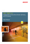
T568A Cable
with a Short and an Open
1
1
2
The 1-2 pair
2 pins are shorted together and2
2 the 7-8 pair is open. The pins
3
with the errors
are flashing. Dash lines (-)33on the bottom
(remote)
display
3
Voice
Tone
Voice Data
Data Video
VideoTone
4
Pass
Rev
X-over
4 the short, while no numbers 4
4on the bottom
Pass line
Rev
X-over
line indicate
indicate
the
Short Split
Split Open
Fail Short
Open
Fail
5
5
open pair.55
Shielded
ShieldedVoltage!
Voltage!ID
ID
6
6
6
6
1
23
34
56
12
45
67
78
8
CableMaster
Tri TesterTMPins
Pins
7
7
8
8
X
1
2
3
4
5
6
7
8
7
7
8
8
1
2
3
4
5
6
7
8
Voice Data VideoTone
Pass X-over Rev
Fail Short Split Open
ShieldedVoltage!ID
12 3 4 5 6 7 8
T568A Cable with a Miswire and Unrecognized Continuity
1 and 2 pins on the main tester are connected to pins 2 and 1 at the
remote-end. The pins with this error are flashing. The “U” for the remote
pin numbers indicates an unrecognizable continuity was detected that is
neither a short or open. An ID remote connected to the Tester when in
cable test mode would also have shown this error.
39
T568A Data Ca
A common error
is to put all the w
T568A
w
1-2, 3-4,Cable
5-6, 7-8
an Ope
correct continuit
The 1-2 pairtopin
designated
be
together
and the
in the middle
of
open. The pins
compatibility
purw
are flashing. Da
designated wire
the bottom (rem
matched accord
indicate the sho
The
“Split”onerror
numbers
the
mismatched
pin
indicate the ope
map of the LCD
Remote
Remote Tester
Tester Pins
Pins
TM
CableMaster
Pins
Tri
TriTester
TesterTM
Pins
Pins
Cable Wiring
T568A Data Ca
Properly
A
commonWired
error
T568B
is
to putisallelectri
the w
T568A,
but
1-2, 3-4, 5-6,swa
7-8
and orange
pair
correct
continuit
will work as long
designated to be
standard is used
in the middle of
run or patch cab
compatibility
pur
A and B creates
designated
In the eventwire
of a
matched
accord
“X-over” icon
wi
The
“Split” error
mismatched
pin
mismatched
wire map. pin
map of the LCD
Remote Tester Pins
Tri
TriTester
TesterTMTM Pins
Pins
1
1
1
1
2
2
2
2
3
3
3
3
Voice
Tone
Voice Data
Data Video
VideoTone
4
4
Pass X-over
X-over Rev
4
4
Pass
Rev
Short
Split
Fail
Fail Short Split Open
Open
5
5
5
5 DISPLAY
Shielded
Voltage!ID
APPENDIX:
CABLE WIRING AND
SCREEN
Shielded
Voltage!
ID
6
6
6
6
34
56
12
45
67
78
23
1
8
7
7
7
7
8
8
8
8
CableMaster 450
Test. Identify. Qualify.
User Manual
Psiber US:
Psiber Data Sytems Inc.
7075-K Mission Gorge Road
San Diego, CA 92120
Phone: +1 (619) 287 99970
e-mail: [email protected]
www.psiber.com
Psiber Europe:
Psiber Data GmbH
Felix-Wankel-Str. 4
82152 Krailling
Germany
Phone: +49 (89) 8913 6060
e-mail: [email protected]
www.psiberdata.com
Psiber Data Pte. Ltd.:
3 Science Park Drive
#03-09 The Franklin
Singapore Science Park 1,
Singapore 118223
Phone: +65-6569-6019
e-mail: [email protected]
www.psiberdata.com
For technical information and support please
contact the Psiber Office in your country.
www.psiberdata.com
40