1
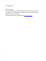
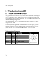
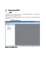
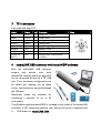
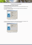
Tensiometer
TS1
Expert user guide
© UMS GmbH München, Version Sept. 2006
TS1 expert guide
Gedruckt am: 29.09.2006
2
Table of contents
1
Description of the self refilling Tensiometer TS1.......................................5
1.1
General.............................................................................................5
1.2
Power supply....................................................................................5
1.3
Output signals ..................................................................................6
1.4
Serial interfaces ................................................................................7
1.4.1
RS485 / tensioLINK ................................................................7
1.4.2
SDI12 ....................................................................................10
1.5
Internal data logger ........................................................................10
1.6
Special version with soil water extraction......................................12
2
TS1 configuration with tensioVIEW..........................................................16
2.1
The UMS tensioLINK USB-converter............................................16
2.2
Work with tensioVIEW ..................................................................17
2.2.1
Menu.....................................................................................17
2.2.2
Searching connected devices ................................................18
2.2.3
User authorisations...............................................................20
2.2.4
Configuration of a device......................................................21
2.3
Configuration settings for the TS1 .................................................22
3
TS1 connection.........................................................................................31
4
tensioLINK USB converter with tensioVIEW software............................31
3
TS1 expert guide
Expert user guide:
This guide describes the extended functions and the serial interfaces of the
Tensiometer TS1. Please read the standard manual for general information
about operation and installation.
All UMS manuals can be downloaded from www.ums-muc.de
4
1
1.1
Description of the self refilling Tensiometer TS1
General
The TS1 combines the principles of a pressure transducer Tensiometer to
measure the soil water tension and a pore water sampler that extracts soil
solution through a porous ceramic: inside the TS1 a bidirectional miniature
pump is integrated between pressure transducer and ceramic cup. A
microcontroller controls the functions of pump and sensors. To refill the cup, a
negative pressure, lower than the actual water tension in the surrounding soil,
is established to draw water into the ceramic cup. Excess water is released
through an exhaust back into the soil.
In a special version the TS1 can be equipped with an additional outlet tube.
Then, the excess water is not discharged through the exhaust, but pumped up
to a sampling bottle at the surface for later analysis. A complete solution for
time-scheduled soil water extraction. Still, the TS1 continuous to work as a
normal Tensiometer.
1.2
Power supply
The TS1 is designed for battery-powered in-the-field operation. Average
current consumption is less than 3 mA. The TS1 should be powered
continuously to ensure the correct performance of automatic refilling and
status control.
Alternatively, the TS1 can be powered in intervals controlled by a data logger.
Please allow a warm-up time of at least 10 seconds. The observing of the filling
status then is limited.
5
TS1 expert guide
1.3
Output signals
The TS1 offers analog signals for soil water tension and soil temperature, and a
digital status of the refilling condition.
Soil water tension and soil temperature are linear voltage signals in a selectable
range of 0 to 1V, 0 to 2 V (standard) or 0 to 5 V. This allows the connection to
almost any logger or data acquisition device.
If an incorrect refilling is detected, the output signal reading will have an error
voltage (default error value -99 kPa or 1 mV). This assures that only correct
readings are stored. The filling condition is detected to be insufficient when a
bubble of a certain size appears and the soil is too dry for automatic refilling,
The filling status signal itself (on the filling status line) is 0 V for a correct filling
condition. If an incorrect filling is detected, the supply voltage is switched
through and the status signal is Vin (= supply voltage). This can be used for
example to switch a visually controllable LED.
If you connect a burden to the digital switch output, for example a LED,
connect the LED where the supply voltage is connected to. If connected
correctly the current will then only go through the positive power supply line
and the digital output line. The GND potential of the TS1, which is also the
reference potential for the voltage outputs, will not be shifted. Therefore, the
burden will not influence the analog outputs..
Any changes of the signal ranges or the alarm function can be set with the
Windows tensioVIEW software. The sensor is connected to a PC's USB
interface with the tensioLINK converter cable. Both are available as accessories.
6
rt
V
V
I
gn
gb
ws
8x0,35 Ly-Cy
Tensiometer
gr
I
bl
rs
I
bn
bn
Figure 1: Correct connection of the TS1
1.4
Serial interfaces
The TS1 offers two serial interfaces. The RS485 compatible tensioLINK
interface requires the tensioLINK-USB-converter and the Windows software
tensioVIEW. All functions like taking direct readings in the lab, downloading
stored readings and configuration can be executed. With RS485 a robust and
less-costly bus network of sensors with cable lengths up to 1000 meters can be
established. Data loggers with RS485 can read tensioLINK sensors directly.
Additionally a SDI12 interface is available for connection to SDI12 bus systems.
The SDI12 interface has to be activated with the tensioVIEW software. Then,
one of the 2 analog lines is disconnected and used as the SDI12 line.
1.4.1
RS485 / tensioLINK
The RS485/tensioLINK 2-wire interface is available on wire 6 (pink) and 7
(blue). Power supply is connected to wire 1 (white) and 2 (brown). The other
wires are not required for operation with tensioLINK.
Wire colours are appropriate for UMS standard connecting cables only.
7
TS1 expert guide
RS485 defines the physical interface. Other than for example RS232, RS485
signals are transferred differentially between both lines. Thus, electromagnetic
interference is reduced. Related to the supply GND signals do fluctuate (so
called Common Mode Range). With RS485 even moderate fluctuations in a
range of -7 und +12V are suppressed.
RS485 is bus-compatible, which means 2 or more units can communicate with
each other. The 2-wire signal lines are connected parallel. There is one sending
unit while all other units, i. e. sensors, are listening to the line. Thus, a message
is received by all units.
The cabling of RS485 is very flexible. Connect the lines in loops or branches.
Connecting cables and distributor boxes are available as accessory (see Fehler!
Verweisquelle konnte nicht gefunden werden.). For cable lengths in 100 meter
ranges no special arrangements have to be observed. With cable lengths of 1
km it is necessary to check the correct connection and look for possible
potential differences.
RS485 is the interface type, and tensioLINK is the protocol for the data
transmission. Other known RS485 protocols, like Profibus or Modbus, are
often very extensive, making it difficult to integrate low-cost or low-power
sensors. Other than that, the UMS tensioLINK protocol is a proprietary
program specially developed for a certain application.
Please contact us for a description of the protocol. The protocol has a simple
structure for possible implementation in certain data loggers or other devices.
Some specifications of the tensioVIEW protocol:
8
Type
Multi-Master
Collision recognition /
treatment
Retry
Serial data transmission
speed
Standard 9600 Baud,
max. 115200
Error detection
Checksum
Error correction
None, Retry
9
TS1 expert guide
1.4.2
SDI12
SDI12 is a very simple interface for sensors and is often used for irrigation
systems.
SDI12 requires only 3 lines: the two power supply wires 1 (white) and 2
(brown) and one signal wire (red). In the TS1 the signal wire uses the analog
output 2 line. When SDI12 is activated this analog output is not available. The
analog output is not needed anyway when the sensor is connected as serial.
SDI12 defines levels for 0 and 1 similar to TTL. The data transmission speed is
1200 Baud. Due to the single line the maximum cable length for SDI12 is 60
meters and the maximum number of connectable units is 10.
For more specification of the signal level and the protocol please look at the
webpage of the SDI12 Support Group: http://www.sdi-12.org
The TS1 is fully compatible to the specifications of the SDI12 Support Group!
1.5
Internal data logger
The internal data logger of the TS1 stores readings in a non-volatile memory
and has a capacity of up to 3500 data sets including tension and temperature
reading. The period when to upload the memory depends on the selected
interval:
Interval for taking readings
10
Memory is full after
1 minute
58 hours
10 minutes
24 days
30 minutes
73 days
1 hour
145 days
6 hours
875 days
12 hours
1750 days
Please note the following remarks about the data logger:
1.
The internal clock of the TS1 is not as accurate as in specific high-end
data loggers. To reduce the time drift, the clock needs to be
synchronized regularly.
2.
The Tensiometer has no battery buffer for the internal clock. If the
Tensiometer is disconnected from power while the data logging is
activated, the time is lost. The Tensiometer cannot recognize, when
the last reading was stored, the time interval between the last and the
second last reading is lost.
Determination of the time of storage for data sets
When the logging of a Tensiometer is started (connected to power or change
of the configuration), the first data set will be marked with a parameter DF=0.
Then, a new data set is taken and put in the memory after the set interval has
elapsed. Every new data set is marked with DF=1 if operation in continuous.
DF=1 means readings were taken in the selected interval. Thus, the actual
time of storage can be determined for each data set from the interval length
and the interval number.
In case the Tensiometer has been disconnected from power, the first data set
after reconnection will be marked with DF=0. The following readings will be
taken in the set interval again, but without a correct starting time the time of
storage cannot be determined anymore. There are only restricted possibilities
to reconstruct the actual time of storage.
11
TS1 expert guide
Data sets are
Datensätze sind
continuous
fortlaufend
Data sets not
Datensatz
continuous,ist
nicht
fortlaufend
interval
d.h. Aufzeichnungsunknownunbekannt
intervall
Figure 2: Mark for continuity of data sets
1.6
Special version with soil water extraction
In the standard version of the TS1 water is drawn up from the soil through the
ceramic to refill the cup during the refilling process. The excess water is
discarded back into the soil through the exhaust.
With the special version TS1 water is extracted from the soil, but, instead of
discarding it, it is conducted through a tube to the surface where it can be
collected. This version has no exhaust.
12
Figure 3 (left): TS1 with exhaust outlet (left)
Figure 4 (right): TS1 with soil water sampling tube leading to the surface
13
TS1 expert guide
The time of day and the day itself when the extraction should be executed as
well as the amount of solution can be programmed. For example program an
extraction of 15 ml of solution every Monday at 7 o'clock when the solution
should be collected Monday afternoon.
During a extraction process, the Tensiometer does not take tension readings.
The data set is marked with an error value. The Tensiometer continues to take
normal readings after the extraction is finished.
The fine pores of the ceramic only allow small amounts of solution to be
extracted. Still, depending on the soil structure, an extraction with soil water
tensions of up to 650 hPa are possible.
14
Figure 5: Configuration menu
Program the difference of the extraction tension and the actual soil water
tension to have a constant pressure potential even during the extraction
process. The selected difference should be as small as possible to minimise soil
interference. The default value is 100 hPa. Reduce this value to find out the
best value for your type of soil.
15
TS1 expert guide
2
TS1 configuration with tensioVIEW
2.1
The UMS tensioLINK USB-converter
The tensioLINK converter has a power supply that is galvanically isolated from
the PC or notebook power supply. Sensors are connected to the tensioLINK
directly and are powered by the converter. The pin configuration is identical to
UMS standard plug configurations.
Link several sensors with bus distributor boxes. Check chapter 1.4.1 when
using your own cables.
If sensors should be supplied by another power source take notice to avoid
potential differences. This can be achieved by connecting the GND of both
power sources. The V+ line of the USB converter then is not used.
Configuration of the USB converter:
Signal
Colour
Vout
white
1
Supply +7…+10 VDC
GND
brown
2
Supply minus
n.c.
green
3
-
n.c.
yellow
4
-
n.c.
grey
5
-
RS485-B
pink
6
RS485 2-wire B
RS485-A
blue
7
RS485 2-wire A
n.c.
red
8
-
16
Pin
Function
Plug
8 pol. female plug
2.2
Work with tensioVIEW
2.2.1
Menu
tensioVIEW has a simple menu for mostly self-explaining
configuration of tensioLINK devices.
read-out and
After starting tensioVIEW the display is more or less blank, most functions are
inactivated.
Gerätesuche
Search for connected devices
starten
Select single
Einzelgerätemodus
/
Mehrgerätemodus
device mode /
wählen
multiplex
device mode
Figure 6: tensioVIEW menu
17
TS1 expert guide
2.2.2
Searching connected devices
If one or more sensors are connected via the USB-converter they can be
searched by pressing the loupe button.
tensioVIEW offers two options for searching:
Single device mode
If only one device is connected, tensioVIEW will find this device very quick.
This mode is not functional if more than one device is connected!
Multiplex device mode
tensioVIEW is able to detect up to 256 devices connected to the bus within 8
seconds, but only if each device is already personalised with an individual bus
identification address. If two or more devices have an identical address, none of
them will be found.
All devices found will be displayed in the left section as a directory tree. Same
types of devices will be grouped in one directory.
18
Folder
devices
Ordnerforfür
Geräte
of
the same
eines
Typstype
Device
Gerät
Figure 7: Found devices in tensioVIEW
Detected devices will be displayed with their programmed names. Press the +
symbol to see what readings the device can offer. Double-click on the name to
open a menu window where all specifications and functions of this device are
displayed. Depending on the type different registries are available. The first
shows an overview of the current settings and information about address
number or error messages.
19
TS1 expert guide
Figure 8: Settings menu
2.2.3
User authorisations
The status of the user authorization can be selected between:
Public or Power
Select the authorization status by clicking on the button on the bottom menu
bar.
20
Figure 9: festlegen der Benutzerrechte
Select the authorization
status
Benutzerrechte
festlegen
The Public status should be selected for standard applications. This offers all
features to work with a standard system and standard devices.
The Power status offers more features required for special applications. Please
use this option only if you are already familiar with the system and know the
meaning of all settings. Programming false parameters might cause instabilities.
2.2.4
Configuration of a device
Select the register "Configuration“ for viewing and changing the programmed
settings of the device.
21
TS1 expert guide
Figure 10: Configuration menu
Depending on the authorization status, only parameters that can be edited are
shown. To store it in the device. a changed parameter has to be sent to the
device by pressing the "Upload“ button. A message notifying about the
successful configuration will be displayed.
Configuration changes are effective immediately. Tensiometers for example
will re-start just as if they were connected to power.
2.3
Configuration settings for the TS1
Those settings which are editable only for Power users are marked with an
asterisk *.
22
tensioLINK
Bus number
tensioLINK bus number of the device
Sub address
tensioLINK sub address of the device
Explanation:
tensioLINK uses two types of address for each device, the bus address and the
sub address. The reason for this is that is there might be sensors installed at the
same spot, but with different measuring depths (for example multi-level
probes). In this case, the sub address defines the depth starting with 1 for the
highest sensor.
Furthermore, the sub address could be used to combine groups of sensors, for
example of one measuring site.
In general the required identification for a device is always the bus number. If
more than 32 devices are connected to the bus the sub address is counted up.
The allowed numbers for the bus address are 1 to 32 and for the sub address 1
to 8.
The default value for both bus and sub address is 0. With more than one device
connected individual addresses have to be declared.
Serial interface activated during power down*
Serial reception possible in sleep mode. When data are received thorough the
RS485 interface the TS1 is wakened, With an activated reception the TS1
consumes approximately an additional 0.5 mA.
SDI-12
SDI12 interface activated
Switch on the SDI12 bus. The analog output 2 then will be disconnected.
SDI12 Sensor Address
SDI12 sensor address.
23
Device information
Device name
Individually editable name of the Tensiometer in ASCII. Maximum length 12
digits
Calibration date
Date of the last calibration. In general sensors should be recalibrated and
checked after two years.
Installation depth
Here the installation depth can be entered. This is for your information only
and has no further functions.
Installation angle
Installation angle selectable from 0° to 180°. If activated the water column
inside the ceramic cup will be compensated in relation to the installation angel.
(0° means the Tensiometer is installed vertically).
Soil type
Type of soil at the installation site: Only for information, does not influence the
Tensiometer readings.
Ceramic Type*
For special ceramics for compensation of the installation angle only.
Compensation length
Effective length of the total water column in [0.1 cm] for compensation of the
installation angle.
System
Power Save Mode
The Power Save Mode puts the Tensiometer to sleep when inactive. Analog
outputs are then switched off and the current consumption is significantly
reduced. If data is read out only serially, or the internal data logger is used,
activate this option without reducing the Tensiometer operation. Possibly the
Tensiometer will react a little bit slower to serial commands.
Time span for power save mode
Time span after which the next power down is activated after connecting the
power supply or after the reception of a serial command. After this time span
the Tensiometer goes to the power save mode when no serial communication
is transmitted or no job has to be executed. Possibly the Tensiometer will react
a little bit slower to serial commands.
Minimised battery voltage
Lower limit for the battery voltage [V*10]. Normally the TS1 quits operation
when the battery voltage is less than 6 V. If you do not use the analog outputs,
and if the Tensiometer will be connected to a sufficient power supply higher
than 6 V whenever the data is downloaded (for example the USB converter),
this limit can be reduced. If the limit is set to for example 3 V the TS1 will
operate correctly down to this voltage. Still, the analog outputs and serial
communication is functional only down to 5.5V.
Maximum battery voltage
Upper limit for the battery voltage. [V*10].
Data logger
Interval
Logging interval (read 1.5)
Ring buffer memory
With ring buffer activated the oldest readings are overwritten when the
memory space is full.
25
TS1 expert guide
Sensor readings
Continuous measurements
Activate the quick updating of readings to receive the Tensiometer readings
instantly, for example during a refilling procedure. Measurements are taken in
intervals of 50 ms. Note the rise in power consumption and that the reaction
to serial commands might be slowed down. The setting "Measuring interval“ is
deactivated during this mode..
Measuring interval
This is the standard interval in which sensor measurements are refreshed and
available on the analog lines.
Water column compensation active
Activates the automatic compensation of the effective water column (inside the
ceramic cup) which depends on the installation angle. Please check the manual
of each device for the length of the water column.
Continuous measurement after power up
Continuous measurement without interval control for 60 seconds after
powering up the device.
Pressure transducer temperature compensation
Activates the temperature compensation for the pressure transducer.
External sensor
Type of an external sensor connected to the internal analog interface. This
Parameter is used for configuration of an external sensor connected to the
internal board.
Analog Outputs (DAC)
DACA active
Turns on the analog output 1 (standard use pressure)
DACB active
Turns on the analog output 2 (standard use temperature)
26
Associate reading DACA
A sensor reading can be associated to analog output 1. Standard for analog
output 1 is pressure.
Associate reading DACB
A sensor reading can be associated to analog output 2. Standard for analog
output 2 is temperature.
Associate depth DACA
For multilevel probes the DACA reading can be associated to a certain depth.
Then, tensioLINK will take readings using the same bus address plus the sub
address. For the default value depth = 1 the internal sensor readings are used.
Associate depth DACB
Associate a depth to reading DACB.
DAC error output
Error output value for DAC [mV]. If an incorrect reading occurs (e. g. filling
status insufficient) this voltage value will be put on the analog output.
DAC output range
Set the output range of the analog reading to 0 to 1 V; 0 to 2 V or 0 to 5 V. A
sensor reading will be amplified within this range, for example -100 kPa to
+100 kPa can correspond to 0 to 2 V.
DAC temperature output range
Output range for temperature.
DAC pressure output range
Output range for pressure.
Digital output
Digital output power saving
Activate the power saving function of the digital output. Any burden connected
to the digital output will be powered shortly every 5 seconds (e. g. a LED will
blink every 5 s indicating a malfunction)
Function of the digital output
Evaluation through a table. If the digital output is used for control of the filling
status, 1 indicates a poor filling status.
27
TS1 expert guide
If used as a comparator the value of a reading is compared to the set threshold
(see "Lower threshold"). If used as a window comparator the reading is
compared with both threshold values. In case the reading is in between both
threshold values the digital output is set to 1.
Associate reading to digital output
This is the relevant reading for the comparator.
Associate depth to digital output
The depth value for comparator, 1 = individual sensor (see "Associate depth
DACA“)
Lower threshold integer
Integer part of the lower threshold or window threshold value.
Upper threshold integer
Integer part of the upper window threshold.
Lower threshold decimal
Decimal part of the lower threshold or window threshold.
Upper threshold decimal
Decimal part of the upper threshold or window threshold.
Configuration example for the digital output:
Function of the digital output = comparator
Associated reading on digital output = temperature
Integer part of the lower threshold = 24
Decimal part of the lower threshold = 3
Æ if temperature is higher than 24.3° the digital output is set to 1.
Filling status testing
BDT measuring interval
Interval in which the filling status is checked with the Thermistor (BDT)
method.
BDP activate filling status with pump method
28
Activate or deactivate the filling status test with the pumping method (BDP).
With this method the air volume inside the ceramic cup is detected. If the air
volume threshold is passed, the automatic refilling will start.
BDP threshold
Maximum value of the air volume which is acceptable.
BDP priority
Select the digital output of the filling status, either the status detected by the
pumping method [on] or by the Thermistor method [off]. This setting does not
effect the refilling function.
Automatic refilling
Threshold for filling status
Value in 0.1 ml after which the filling is regarded to be ok (stop criterion).
Upper suction limit
Upper window threshold when to switch of the pump. During the refilling the
negative pressure inside the cup changes within upper limit (higher negative
presure) and lower limit (lower negative pressure).
Lower suction limit
Lower window threshold when the pump is switched off (lower limit).
Function
Select the function of the refilling. The filing status is regularly tested [Interval]
or tested in dependence of the soil properties [Auto] by the BDP pumping
algorithm. If the threshold is exceeded the automatic refilling is started.
Interval
Interval for an periodical refilling: selectabel from 1 to 32 days. This interval is
only considered when the function is set to "Interval".
Frost protection
Frost protection
With this function activated the ceramic cup is emptied automatically when the
temperature drops below a preset temperature value. Thus, the damage of the
cup by freezing of the filling water is prevented.
29
TS1 expert guide
Threshold value for frost protection
Temperature value [°C] when the automatic empting should be started.
Soil water extraction
Activate soil water sampling
Activate the soil water sampling.
Sampling amount
Volume of the solution to be sampled [ml].
Starting time
Daily time when the extraction is started. Please note that the current time and
date have to be set correctly.
Extraction efficiency
Efficiency of the soil water sampling [%]. If the amount of the sampled solution
does not correspond to the expected amount this correction factor can be
applied..
Weekday table
An extraction is only executed on days which are marked in the weekday table.
Pressure difference
Difference of suction pressure and soul water pressure (Suction control).
During the extraction the pressure difference is kept constant (see 1.6).
30
3
TS1 connection
8 pin cable and plug M12
Signal
Color
Pin
Vin
white
1
Supply +6…+20 VDC
GND
brown
2
Supply minus
A-OUT+1
green
3
Analog output 1 (pressure)
A-OUT-
yellow
4
Analog minus
digital OUT
grey
5
Irrigation signal digital
RS485-B
pink
6
RS485 2-wire B
RS485-A
blue
7
RS485 2-wire A
red
8
Analog output 2 (temperature)
A-OUT+2
SDI12
4
/
Function
Pins
or SDI12
tensioLINK USB converter with tensioVIEW software
With the tensioLINK USB converter
sensors and devices with serial
tensioLINK interface and 8-pin plug M12
can be connected directly to a PC USB
port. Then, the sensor configurations can
be edited and readings can be taken
online. Instruments are powered through
the USB port.
Distributor boxes are available for
connecting a network of up to 32
instruments.
The Windows software tensioVIEW is included to any order of the tensioLINK
converter. A CD containing software, user manual and driver is supplied with
it.
UMS order no.: tensioLINK-USB
31
TS1 expert guide
Contact:
Dipl.-Ing. Andreas Steins
email: [email protected]
UMS umweltanalytische Meßsysteme GmbH
Gmunderstraße 37
D – 81379 München
Telefon : +49 89 1266 52-0; Fax : –20
www.ums-muc.de
32