1
Matisse User's Guide
Version 1.8
i
Contents
Matisse Preface
4
Environmental Specifications .......................................................................................................................6
CE Electrical Equipment Requirements ............................................................................................6
Environmental Specifications............................................................................................................6
Standard Units ..............................................................................................................................................7
Unpacking and Inspection ............................................................................................................................8
System Components ..........................................................................................................................8
Service Box .......................................................................................................................................8
CE Declaration of Conformity....................................................................................................................10
Safety Precautions
11
Precautions for the Safe Operation of Class IV High Power Lasers...........................................................11
Dangers Caused by Laser Dyes and Solvents.............................................................................................13
Focused Back Reflection Danger................................................................................................................14
Matisse Laser Description
15
Laser Head: Titanium:Sapphire Models .....................................................................................................16
Optical Set-Up : Matisse-DR......................................................................................................................19
Controls Box Front and Rear Panel Features..............................................................................................21
Matisse-TR Specifications..........................................................................................................................24
Matisse-DR Specifications .........................................................................................................................26
Required Dye Solvents ....................................................................................................................28
Matisse Reference Cell ...............................................................................................................................29
Single-Frequency Tunable Laser Physics
30
Principle Laser Set-up.................................................................................................................................31
Frequency-Selective Elements....................................................................................................................33
Birefringent Filter............................................................................................................................34
Thin Etalon ......................................................................................................................................34
Piezo Etalon Description .................................................................................................................35
Piezo Etalon Dither..........................................................................................................................37
Optical Diode (Unidirectional Device)............................................................................................38
Frequency Stabilization
39
'Side of Fringe' frequency stabilization.......................................................................................................40
Pound-Drever-Hall frequency stabilization ................................................................................................42
Frequency Drift Compensation...................................................................................................................45
Using your own reference for stabilizing....................................................................................................46
Basic Matisse Operation
47
Start-Up Matisse-Ti:Sa ...............................................................................................................................47
Start-Up Matisse-D.....................................................................................................................................48
Matisse Power Optimization.......................................................................................................................51
Cavity Mirror Optimization.............................................................................................................52
Contents
ii
Thick Piezo Etalon Optimization.....................................................................................................53
Thin Etalon and Birefringent Filter Optimization ...........................................................................54
Frequency Setting .......................................................................................................................................58
Frequency Scanning....................................................................................................................................61
Shut-Down Matisse-T.................................................................................................................................62
Shut-Down Matisse-D ................................................................................................................................62
Matisse Commander
63
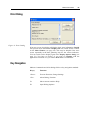
Installation ..................................................................................................................................................63
Version Changes.........................................................................................................................................63
Matisse Commander 1.6 ..................................................................................................................63
Matisse Commander 1.8 ..................................................................................................................64
General........................................................................................................................................................64
Start-Up ...........................................................................................................................................65
Error Dialog.....................................................................................................................................66
Key Navigation................................................................................................................................66
Wavemeter Support .........................................................................................................................67
Firmware Update .............................................................................................................................67
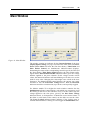
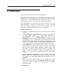
Main Window .............................................................................................................................................68
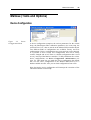
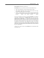
Matisse (Tools and Options).......................................................................................................................69
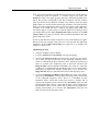
Device Configuration ......................................................................................................................69
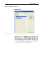
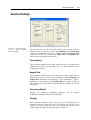
Advanced Options & Tools .............................................................................................................71
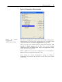
Control Switch-Off Level................................................................................................................74
Powermeter......................................................................................................................................75
Motor Status ....................................................................................................................................75
Display Options ...............................................................................................................................76
Birefringent Filter .......................................................................................................................................76
Goto Birefringent Filter Position .....................................................................................................76
Birefringent Filter Scan ...................................................................................................................77
Birefringent Filter Calibration Table ...............................................................................................79
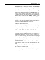
Thin Etalon .................................................................................................................................................81
Thin Etalon Control Setup...............................................................................................................81
Thin Etalon Scan .............................................................................................................................82
Piezo Etalon ................................................................................................................................................83
Piezo Etalon Control Setup..............................................................................................................84
Advanced Settings:..........................................................................................................................85
Piezo Etalon Waveform...................................................................................................................86
S Stabilization.............................................................................................................................................88
Fast Piezo Control Setup .................................................................................................................90
Slow Piezo Control Setup................................................................................................................92
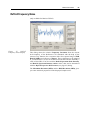
RefCell Waveform...........................................................................................................................93
RefCell Frequency Noise.................................................................................................................94
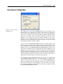
RefCell Properties Measurement.....................................................................................................95
X Stabilization ............................................................................................................................................98
Pound-Drever-Hall Control Setup .................................................................................................100
Pound-Drever-Hall Waveforms.....................................................................................................102
Pound-Drever-Hall Frequency Noise ............................................................................................104
Pound-Drever-Hall Error Signal Measurement .............................................................................105
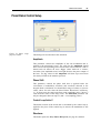
Scan ..........................................................................................................................................................106
Scan Setup .....................................................................................................................................106
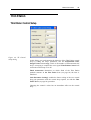
Scan Device Configuration............................................................................................................108
ControlScan Setup .........................................................................................................................109
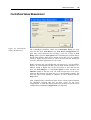
ControlScan Values Measurement ................................................................................................110
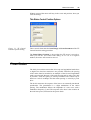
Motor Control ...........................................................................................................................................111
Motor Control Options ..................................................................................................................111
Wavemeter................................................................................................................................................112
Scan Device Calibration with Wavemeter.....................................................................................112
Contents
iii
About ........................................................................................................................................................113
Maintenance
114
Handling of Optical Components .............................................................................................................114
Mirror Exchange.......................................................................................................................................115
Matisse Installation
117
Installation Requirements .........................................................................................................................117
Transport...................................................................................................................................................118
Optical Alignment Procedures..................................................................................................................118
Optical Alignment Procedure: Matisse Ti:Sa ................................................................................118
Optical Alignment Procedure: Matisse Dye ..................................................................................122
Optical Alignment Procedure for the Matisse S Reference Cell ...................................................125
Matisse Electronics
127
DSP Input Charcteristics...........................................................................................................................127
Piezo Amplifier Board Input Characteristics ............................................................................................127
Fast Piezo Amplifier Board Input Characteristics ....................................................................................128
Frequently Asked Questions and Troubleshooting
129
Customer Service
132
Warranty ...................................................................................................................................................132
Return of the Instrument for Repair..........................................................................................................133
Service Centres .........................................................................................................................................134
Problems and Solutions ............................................................................................................................136
Index
137
4
CHAPTER 1
Matisse Preface
Thank you for purchasing the Sirah Matisse laser system.
This manual was written to show you how to safely install, operate,
maintain and service your laser system. An attempt was made to describe
the laser both accurately and completely. However, due to the continuous
progress in technical development discrepancies between manual and
delivered laser system may occur. Before applying pump laser power to
the laser system it is strongly recommended to read this manual
thoroughly and to understand its content.
The first chapter deals with Laser Safety. The Matisse laser, in
combination with a powerful pump laser, is a class IV high power laser.
Its laser radiation represents a serious hazard for your personal health, as
it can permanently damage your eyes and skin. Moreover, inadequate
operation of the laser system may damage other laboratory equipment,
e.g. by ignition of combustible substances or by laser sputtering of
surfaces, as well as the laser system itself, e.g. by focused back
reflections. To minimize the risks connected to laser operation, read this
Chapter thoroughly - and carefully follow the instructions. The Laser
Safety Chapter should be read by all persons working in the laboratory
where laser radiation occurs, even by those not directly involved in laser
operation.
The next chapter contains a general Laser Description, with some details
about the optimum performance range of your Matisse.
The laser's Controls are described in the following chapter.
An concise introduction into Single-Frequency Tunable Laser Physics
and the techniques used for Frequency Stabilization follows.
The operation of your Matisse laser on a day-to-day basis is described in
detail in the next chapter. This chapter contains both, basic operation
hints necessary for your everyday work with the laser system, as well as
more detailed alignment and optimization procedures for all relevant
components of your laser. To keep the laser working at optimum
performance is quite easy as long as you do not totally corrupt the laser
optical set-up. Some effort has been undertaken to illustrate the different
laser optimization possibilities as step-by-step procedures. Please always
read the whole section corresponding to your task before doing the first
step.
The following chapter serves as a description and reference for the
Matisse Commander computer program, with which the Matisse laser is
controlled.
Matisse Preface
5
The Maintenance chapter will deal with all relevant maintenance tasks
necessary for a stable long term operation of your laser system.
If you have to move your Matisse laser to a different location, the Matisse
Installation chapter contains procedures on how to set up the laser and
bring it back to a lasing state.
Matisse Electronics gives additional and more detailed information on the
electronics.
The FAQ and Troubleshooting chapter tries to help you solve some
issues, that you may encounter at some time working with a Matisse laser
In the Customer Service section you will find the addresses of world wide
Service and Sales Centres for Sirah instruments. In case of any question,
remark or problem, please do not hesitate to contact us.
Please read the whole manual before starting to work with your system.
We strongly recommend to keep a laser logbook. You should note all
changes of the mechanical or optical set-up of your laser. Regularly take
notes about obtained laser powers, together with the corresponding pump
power. These notes often simplify the identification of possible error
sources.
Finally, if you encounter any difficulty with the content or the style of
this manual, please let us know. For your convenience, a fax form has
been added at the end of this manual, which will aid in bringing such
problems to our attention.
Matisse Preface
6
Environmental Specifications
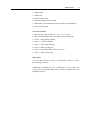
CE Electrical Equipment Requirements
AC power input:
100 .. 240 VAC 50/60 Hz
Power Consumption:
max. 700 W
Environmental Specifications
The environmental conditions under which the laser system will function
are listed below:
Indoor use.
Altitude:
maximum of 3000 m
Temperature:
15 °C to 35 °C
Humidity:
30% to 60%, non-condensing conditions
Insulation category:
1
Pollution degree:
2
Matisse Preface
7
Standard Units
The following units, abbreviation, and prefixes are used in Sirah
Manuals:
Quantity
Unit
Abbreviation
mass
kilogram
kg
length
meter
m
time
second
s
frequency
Hertz
Hz
force
Hewton
N
energy
Joule
J
power
Watt
W
electric current
Ampere
A
electric charge
Coulomb
C
electric potential
Volt
V
resistance
Ohm
Ω
temperature
degree Celsius
°C
pressure
Pascal
Pa
Prefixes
tera
10^12
T
deci
10^-1
d
nano
10^-9
n
giga
10^9
G
centi
10^-2
c
pico
10^-12
p
mega 10^6
M
milli
10^-3
m
femto 10^-15
f
kilo
k
micro 10^-6
µ
atto
a
10^3
10^-18
Matisse Preface
8
Unpacking and Inspection
Your Sirah laser system was assembled, checked and packed with great
care. It was shipped in a container specially designed for this purpose.
Upon receipt of your system, inspect the outside of the shipping
container. If there is any major damage, insist that a representative of the
carrier being present when you unpack the contents. All Sirah laser
containers are equipped with shock and tilt indicators. Carefully inspect
these indicators. If any of them is actuated, insist that a written
confirmation is done on the shipping papers, signed by the carrier.
If the transport boxes are in good condition, and none of the shock and tilt
indicators is actuated, then carefully unpack and inspect the laser system
and all accessory parts. Each system is accompanied by a packing slip
listing all the parts shipped. Verify that your system is complete and
undamaged. In case of any problems, like damaged or missing parts,
please immediately notify the carrier and your Sirah sales or service
representative. Addresses may be found in the Customer Service Chapter.
Keep the shipping containers. If you file a damage claim, you may need
them to demonstrate that damage occurred during transport. If you want
to move your laser to another laboratory building, or if you need to return
the system for service, the specially designed container assures adequate
protection.
System Components
The following components comprise the Matisse laser system:
Matisse laser head
Matisse electronics box
Matisse service box
Matisse dye circulator system (only for dye laser version)
Further components may be supplied together with the laser system,
according to the packing list.
Service Box
Each Matisse laser is delivered together with a service box, containing
some laser accessories and service tools for your everyday work with the
laser, as well as some spare parts. The following items are included in
your service box:
Installation Accessories
1 x Matisse Laser Manual
1 x Matisse Commander Installation CD-ROM
Matisse Preface
9
1 x Mains cable
1 x USB cable
4 x Laser fixing clamps
1 x Filter for purging the laser head
1 x Beam tube, to be installed in between pump laser and Matisse
2 x Laser warning signs
Service Accessories
1 x Set of metric Allen head keys 1.5, 2, 2.5, 3, 4, 5 mm
1 x Set of neutral density filters, for Matisse laser head diodes
1 x Tool 1 : Pump mirror pinholes
1 x Tool 2 : Lyot filter dummy
1 x Tool 3 : Thick etalon dummy
1 x Tool 4 : Beam overlap tool
1 x Tool 5 : Pump beam filter (Ti:Sa laser only)
1 x Tool 6 : Mirror mount ring
Spare parts
1 x Set of spare O-rings, 25 mm x 1.5 mm and 25.1 mm x 1.6 mm,
for mounting of mirrors
Additionally, depending on the configuration of your laser, the
service box may contain further items, which are indicated in a list
included in the box.
Matisse Preface
10
CE Declaration of Conformity
Manufacturer
Sirah Laser- und Plasmatechnik GmbH
Ludwig-Erhard-Str. 10
41564 Kaarst
Germany
Phone: +49 2131 660 651
Fax:
+49 2131 668 095
Product Name
Matisse
Product Types
TR, DR, TS, DS, TX, DX
Directive
Council Directive 73/23/EEC, Low Voltage
Council Directive 89/336/EEC Apendix I, Electromagnetic Compatibility
Applicable Standards
EN 61010-1:2004, Safety requirements for electrical equipment, control,
and laboratory use
EN 60825-1:2001, Safety of laser products Part 1: Equipment
classification, requirements and user's guide
EN 61326-1:1997 + EN 61326-1:1998, Electrical equipment for
measurement, control and laboratory use - EMC requirements
We herewith declare, in exclusive responsibility, that the above specified
instruments were developed, designed and manufactured to conform with
the above Directives and Standards.
Dr. Sven Hädrich
Geschäftsführer, Sirah Laser- und Plasmatechnik GmbH
Kaarst, November 30, 2005
11
CHAPTER 2
Safety Precautions
Precautions for the Safe Operation
of Class IV High Power Lasers
The use of a dye laser system may cause serious hazards if adequate
precautions are not taken. Most of these hazards can be avoided by
appropriate operation of the laser device. However, after a period of
problem-free operation, many users tend to become careless with safety
precautions. Hence you should ensure that all safety rules described in the
following section (and, of course, those prescribed by law) are observed.
The Sirah Matisse laser is operated in combination with a powerful pump
laser (Nd:YAG or Ar+ laser). The laser power of the Matisse depends on
the pump laser power and on the selected wavelength. In any case, the
laser beam of the pump laser as well as the Matisse laser beam have an
extremely high power density. Hence both lasers are able to cause severe
eye and skin damages. Due to the high powers involved even scattered or
specularly reflected laser light are sufficient to produce such injuries.
Furthermore, absorbing and flammable material inadvertently used as a
beam stop poses a fire hazard. Thus working with such laser systems
utmost precautions have to be taken. Pay special attention to all advice
given by the manufacturer of your pump laser.
In the following some general safety rules for the usage of lasers are
given. These recommendations are by no means complete; rather they
constitute the bare minimum of precautionary measures necessary to
avoid laser induced dangers and damages.
Each person working with the laser or present in its operating room
should wear laser-radiation safety goggles. Note that the safety goggles
should give protection against the radiation of all lasers used in the operating
room, which are in each case the pump and the Matisse laser, but also
radiation generated by up or down conversion of the laser light.
Keep the laser closed. This means not only to keep the housing of the laser
closed during laser operation, but also to enclose the emerging laser beam
e.g. in tubes where feasible and to terminate the beam with a suitable beam
stop.
Keep the internal protection sheets and beam stops in place.
Under no circumstances look into the laser beam. For security reasons,
even when the laser is switched off, never look backwards in direction of the
laser beam.
Avoid wearing reflective jewellery while using the laser. Especially
watches are excellent mirrors for laser radiation. Do not risk to reflect the
beam into your eyes by them.
Safety Precautions
12
Never place reflecting surfaces into the laser beam before having
verified where the reflected beam will go. Even absorbers and beam
dumps may reflect a considerable amount of laser power which can be
sufficient to cause severe injuries or damages at the power levels common in
the operation of your laser. The introduction of lenses into the laser beam
requires special caution because its curved surfaces generate additional laser
foci in the reflected beam which are able to destroy optical elements.
Use the pump laser at the lowest possible power level. Especially for
alignment purposes you should use the pump laser at a power level which is
just slightly above the threshold power level of the Matisse laser.
Never expose your skin to the laser radiation.
All laser beams have to be terminated with a beam stop. All experiments
to which the laser is applied have to be designed in such a way that the laser
beams are confined to the experimental set-up. All laser beams for which the
set-up itself does not provide a suitable beam stop have to be terminated
with a beam dump.
Operate the laser only inside distinctly marked areas. The laser should
only be operated inside a room distinctly marked with respective warning
signs and warning lamps. The access to this room has to be restricted to
personnel properly trained.
Do not install the laser in a height that the output is at eye level.
Maintain a high ambient light level in the laser operation area. Eye's
pupils remain constricted, and thus are less sensitive to scattered laser light.
Mark the laser operation area by prominent warning signs.
Safety Precautions
13
Dangers Caused by Laser Dyes and
Solvents
The physical, chemical, and toxicological properties of organic dyes are
not well characterized. Just as the solvents they should be treated as
poisonous. Thus an extreme caution is required in handling these
substances.
During the work with laser dyes eating and drinking are strictly forbidden
inside the laboratory. Always wear protective gloves and a protective
mask when weighing out the laser dye. Following these measures an
inadvertent ingestion of any dye can be excluded. A more likely hazard is
the potential for absorption of solvent or dye solution through the skin.
Even if the solvent itself is not extremely dangerous, some solvents can
penetrate the skin easily and carry the toxic dyes into the body. This is
especially true for solvents as e.g. benzyl alcohol, DMSO
(dimethylsulfoxide), p-dioxane and methanol. Therefore we highly
recommend always to wear protective gloves, laboratory overalls and a
protective mask when handling laser dyes and solvents.
Your chemical supplier can give you further information concerning
storage, handling and waste management of laser dyes and solvents.
Almost all solvents are highly inflammable and volatile, a fact that should
always be remembered when handling these substances. Especially
smoking is strictly forbidden.
In the following list some further safety precautions for the handling of
dye solutions are given:
If possible, use an outlet for handling solvents and dye solutions.
Otherwise, ensure a sufficient ventilation of the workshop place.
Do not eat, drink, and smoke during your work with solvents and dye
solutions.
Avoid all kinds of open fire.
Repair damages or leakage in the dye circulator system immediately
without modifying the technical construction of the pump systems.
Install a suitable fire-extinguisher next to your dye laser.
Safety Precautions
14
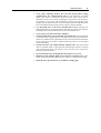
Focused Back Reflection Danger
Focused back reflections of the pump as well as the Matisse laser's beam
represent a serious hazard for both your personal safety and optical
components. Remember that an uncoated glass surface reflects 4% of the
impinging light, and even with an appropriate anti-reflective coating
0.5% of reflection are normal. These reflections may be focused from
both convex and concave surfaces, depending on the orientation of the
surface to the direction of light. In the focus, the light intensity is often
high enough to damage the surfaces of other optical components, and to
represent a serious hazard for eyes and skin.
The optical design of your Matisse laser has been set-up very carefully by
Sirah Laser- und Plasmatechnik GmbH. If you intend to make any
modifications to the pump laser beam path or to the Matisse laser beam
path, then thoroughly check beforehand whether a focused back
reflection may occur. Warranty does not cover damages due to focused
back reflection!
15
CHAPTER 3
Matisse Laser Description
The present chapter gives a brief description of the optical set-up of the
Matisse, as well as its main specifications. For a discussion of optical
details, including step-by-step instructions for system optimizations,
please refer to the next chapters.
Matisse Laser Description
16
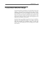
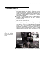
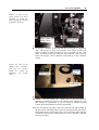
Laser Head: Titanium:Sapphire
Models
Figure 1: Top view of a
Matisse TX laser head.
Figure 2: Optical layout
of a Matisse
Titanium:Sapphire laser.
PM1 Pump Beam Mirror 1. Re-directs the pump laser beam onto the
second pump beam mirror PM2. The mirror is used for steering the pump
laser beam.
PM2 Pump Beam Mirror 2. Focusses the pump laser beam into the
crytsal, through the backside of folding mirror FM1.
FM1 Folding Mirror 1. Restores a parallel beam for the ring laser
beam after amplification by the Titanium:Sapphire crystal.
Matisse Laser Description
17
FM2 Folding Mirror 2. Focusses the ring laser beam into the
Titanium:Sapphire crystal for spatial mode matching with the pump laser
focus.
TiSa Titanium Sapphire Crystal. The laser gain medium. The crystal
is cooled by a temperature controlled water.
EOM Electro Optical Modulator. The non-resonant intra-cavity
electro optical modulator is used for fast change of the optical path length
of the ring cavity. The effect is used for high-bandwidth correction of the
Matisse's emission wavelength. Note: The device is only present in the
Matisse TX.
Thin E Thin Etalon. The thin etalon is used as a bandpass filter. To
provide tunability, the tin etalon is attached to a motor driven mount. A
step motor controls the horizontal tilt angle of the etalon.
BiFi Birefringence Filter. The birefringence filter is used as a coarse
bandpass filter to determine the emission wavelength of the ring laser.
The filter assembly is rotated by a stepper motor.
OC
Output Coupler. The output coupler forms the exit for the laser
beam. A fraction of the beam will be emitted by the laser the rest will be
directed back into the ring cavity. The beam polarization is horizontal.
M2
Out-Of-Plane Mirror M2. This mirror is mounted at a different
beam height level. This will introduce a geometrical rotation of the beam
polarization. The combination of M2 and the TGG plate forms an optical
diode that supports laser activity in a defined direction.
M3
Tweeter Mirror M3. This mirror is mounted on a piezoelectric
actor. Changing the voltage applied to the actor will change the position
of the mirror and ultimately the optical path length of the cavity. The
effect is used for mid-bandwidth correction of the Matisse's emission
wavelength. Note: The Matisse TR has no active control of the emission
wavelength, in this case the mirror is fixed directly to the mount.
TGG TGG Plate. The TGG plate is made from Terbium-GalliumGarnet and acts as a Faraday-rotator when exposed to a strong magnetic
field. The combination of M2 and the TGG plate forms an optical diode
that supports laser activity in a defined direction. Note: The magnetic
field is generated by two powerful permanent magnets. Be careful when
using tools close to the device.
Piezo E Piezo Etalon. The piezo etalon selects a single longitudinal mode
from the spectral range that is determined by the configuration of output
coupler, birefringence filter, and thin etalon. To maintain the exact match
of etalon and longitudinal mode the spacing of the etalon is dithered by
an piezoelectric actor and a lock-in scheme is used to control the etalon
spacing.
Matisse Laser Description
18
TM
Tuning Mirror. The exact emission wavelength of the cavity is
determined by it's length. The tuning mirror is attached to a long stroke
piezoelectric actor to allow the selection of this wavelength. This device
is used for low-bandwidth (woofer) correction of the Matisse's emission
wavelength, when active wavelength control is enabled (only available in
Matisse TS and TX models).
DI
Integral Diode. The lock-in control for the piezo etalon requires
the measurement of the temporal behaviour of the integral intensity of the
ring laser. For this purpose the leak intensity on the backside of the outof-plane mirror M2 is used.
DE
Etalon Diode. The control loop for the thin etalon requires the
measurement of the back reflection of the entrance surface of the etalon.
This diode measures the reflected intensity.
Matisse Laser Description
19
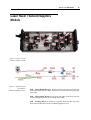
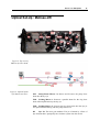
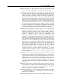
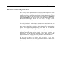
Optical Set-Up : Matisse-DR
Figure 3: Top view of
Matisse dye laser head.
Figure 4: Optical layout
of a Matisse dye laser.
PM
Pump Beam Mirror. Re-directs and focusses the pump laser
beam into the dye jet.
FM1 Folding Mirror 1. Restores a parallel beam for the ring laser
beam after amplification by the dye jet.
FM2 Folding Mirror 2. Focusses the ring laser beam into the dye jet
for spatial mode matching with the pump laser focus.
DJ
Dye Jet. The laser gain medium. The jet is formed by a flow of
dye solution that is pumped by the circulator system into the nozzle.
Matisse Laser Description
20
BiFi Birefringence Filter. The birefringence filter is used as a coarse
bandpass filter to determine the emission wavelength of the ring laser.
The filter assembly is rotated by a stepper motor.
OC
Output Coupler. The output coupler forms the exit for the laser
beam. A fraction of the beam will be emitted by the laser the rest will be
directed back into the ring cavity. The beam polarization is horizontal.
M2
Out-Of-Plane Mirror M2. This mirror is mounted at a different
beam height level. This will introduce a geometrical rotation of the beam
polarization. The combination of M2 and the TGG plate forms an optical
diode that supports laser activity in a defined direction.
M3
Tweeter Mirror M3. This mirror is mounted on a piezoelectric
actor. Changing the voltage applied to the actor will change the position
of the mirror and ultimately the optical path length of the cavity. The
effect is used for mid-bandwidth correction of the Matisse's emission
wavelength. Note: The Matisse DR has no active control of the emission
wavelength, in this case the mirror is fixed directly to the mount.
TGG TGG Plate. The TGG plate is made from Terbium-GalliumGarnet and acts as a Faraday-rotator when exposed to a strong magnetic
field. The combination of M2 and the TGG plate forms an optical diode
that supports laser activity in a defined direction. Note: The magnetic
field is generated by two powerful permanent magnets. Be careful when
using tools close to the device.
Piezo E Piezo Etalon. The piezo etalon selects a single longitudinal mode
from the spectral range that is determined by the configuration of output
coupler, birefringence filter, and thin etalon. To maintain the exact match
of etalon and longitudinal mode the spacing of the etalon is dithered by
an piezoelectric actor and a lock-in scheme is used to control the etalon
spacing.
Thin E Thin Etalon. The thin etalon is used as a bandpass filter. To
provide tunability, the tin etalon is attached to a motor driven mount. A
step motor controls the horizontal tilt angle of the etalon.
EOM Electro Optical Modulator. The non-resonant intra-cavity
electro optical modulator is used for fast change of the optical path length
of the ring cavity. The effect is used for high-bandwidth correction of the
Matisse's emission wavelength. Note: The device is only present in the
Matisse DX.
TM
Tuning Mirror. The exact emission wavelength of the cavity is
determined by it's length. The tuning mirror is attached to a long stroke
piezoelectric actor to allow the selection of this wavelength. This device
is used for low-bandwidth (woofer) correction of the Matisse's emission
wavelength, when active wavelength control is enabled (only available in
Matisse DS and DX models).
Matisse Laser Description
21
DI
Integral Diode. The lock-in control for the piezo etalon requires
the measurement of the temporal behaviour of the integral intensity of the
ring laser. For this purpose the leak intensity on the backside of the outof-plane mirror M2 is used.
DE
Etalon Diode. The control loop for the thin etalon requires the
measurement of the back reflection of the entrance surface of the etalon.
This diode measures the reflected intensity.
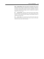
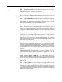
Controls Box Front and Rear Panel
Features
Figure 5: Front view of
Matisse control box.
1 Power switch. Turns the entire unit On and Off.
2 Voltage indicators. Light up when the respective voltage is available
in the control unit (LED).
3 DSP signal input select. Selects the internal or an external signal
source for the digital signal processor (DSP).
4 DSP external input. SMA connector to feed an external signal into
the DSP unit.
5 USB connector. Connects the unit to the USB.
6 USB indicator. Lights up when the USB is transferring data (LED).
7 Tuning mirror input select. Selects the internal or an external signal
source for the piezoelectric actor that controls the tuning mirror.
8 Tuning mirror external input. SMA connector to feed an external
signal into the amplifier module.
Matisse Laser Description
22
9 Tweeter mirror input select. Selects the internal or an external
signal source for the piezoelectric actor that controls the tweeter
mirror.
10 Tweeter mirror external input. SMA connector to feed an external
signal into the amplifier module.
11 Reference cell input select. Selects the internal or an external signal
source for the piezoelectric actor that controls the reference cell
spacing.
12 Reference cell external input. SMA connector to feed an external
signal into the amplifier module.
13 Thin etalon manual control. Two-way switch to control the stepper
motor that controls the tilt of the thin etalon.
14 Thin etalon indicator. Lights up when the etalon motor is running
(LED).
15 Thin etalon error. Lights up when an error condition is present at the
etalon motor controller unit (LED).
16 Birefringent filter manual control. Two-way switch to control the
stepper motor that controls the rotation of the birefringent filter
assembly.
17 Birefringent filter indicator. Lights up when the etalon motor is
running (LED).
18 Birefringent filter error. Lights up when an error condition is
present at the etalon motor controller unit (LED).
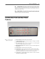
Figure 6: Rear view of
the Matisse electronics
box.
1
X1 Connector. This mixed signal sub-D connector is used to connect
the laser head to the control unit.
Matisse Laser Description
23
2 X2 Connector. This mixed signal sub-D connector connects the thin
etalon stepper motor with the control unit.
3 X3 Connector. This mixed signal sub-D connector connects the
birefringent filter stepper motor with the control unit.
4 AC Input Connector. This connector also holds the fuse for the unit.
Rating 1.6 A, 250 VAC
Matisse Laser Description
24
Matisse-TR Specifications
This section summarizes the specifications of the Matisse-TR laser.
Please note that specifications are subject to change without notice.
Tuning range
Pump laser
Optics set
Output range
Millennia Pro 10s
MOS-1
700 .. 780 nm
Millennia Pro 10s
MOS-2
750 .. 870 nm
Millennia Pro 10s
MOS-3
860 .. 990 nm
Power Output
at approximately 780 nm
Pump laser
Specified power
Millennia Pro 5s
800 mW
Millennia Pro 10s
1800 mW
General Characteristics
Spatial Mode
TEM00
Beam Diameter (at typical 1.4 mm
Matisse output port)
Beam Divergence
< 2 mrad
Linewidth
< 10 MHz rms
Amplitude Noise
1.5% rms
Beam polarization
horizontal
Requirements
Pump laser
Millennia Pro Series (or similar)
Matisse Laser Description
Pump laser power
5 .. 20 W
Ambient conditions
constant temperature in the 20 .. 25°C range,
25
non condensing humidity conditions
Cooling
required for crystal (< 10 W)
Laboratory
vibrational isolated optical table,
dust-free air (flow box)
Electrical
100 .. 250 V, max. 2.5 Amps
Computer control
Windows 2000 or Windows XP system, USB
port
Matisse Laser Description
26
Matisse-DR Specifications
This section summarizes the specifications of the Matisse-DR laser.
Please note that specifications are subject to change without notice.
Tuning range
Pump laser
Optics set
Output range
Millennia Pro 10s
MOS-4
550 .. 660 nm
Millennia Pro 10s
MOS-5
650 .. 780 nm
Power Output
at the output maximum of the Rhodamine 6G tuning curve :
Pump laser
Specified power
Millennia Pro 5s
550 mW
Millennia Pro 10s
1600 mW
General Characteristics
Spatial Mode
TEM00
Beam Diameter (at typical 1.4 mm
Matisse output port)
Beam Divergence
< 2 mrad
Linewidth
< 20 MHz rms
Amplitude Noise
3.5% rms
Beam polarization
horizontal
Requirements
Pump laser
Millennia Pro Series (or similar)
Pump laser power
5 .. 20 W
Matisse Laser Description
Ambient conditions
27
constant temperature in the 20 .. 25°C range,
non condensing humidity conditions
Laboratory
vibrational isolated optical table,
dust-free air (flow box)
Electrical
100 .. 250 V, max. 2.5 Amps
Computer control
Windows 2000 or Windows XP system, USB
port
Matisse Laser Description
28
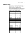
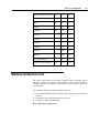
Required Dye Solvents
Required solvents to be used with the Matisse dye circulators are
Ethylene Glycol (EG), Ethylene Glycol Phenyl Ether (EPH) and
Propylene Glycol Phenyl Ether (PPH), because of their lubricant
properties. Other solvents will damage the dye circulators!
The dye concentration should be chosen in that way, that at least 85% of
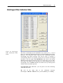
the pump power is absorbed. The following table contains solubility data
(g/l) for various dyes in the required solvents (courtesy of Exiton Inc.)
Solubility of Dyes in EG / EPH / PPH (grams/liter)
Dye
EG
EPH
PPH
BPBD-365
-
17.3
7.5
PBD
-
16.5
10.4
Exalite 389
low
≥ 2.7
≥ 4.1
Exalite 392A
low
0.5
1
Exalite 400E
9.65
≈ 0.13
0.4
Coumarin 480
0.72
83
68
Coumarin 515
3.4
5.5
5.8
Coumarin 535
-
12.6
4.3
Coumarin 540
-
5.3
3.6
Pyrromethene 546
low
0.99
0.9
Pyrromethene 556
8.1
-
insol.
Pyrromethene 567
< 0.09
84
≈7
Pyrromethene 580
-
5.9
7.7
Pyrromethene 597
-
7
9.2
Pyrromethene 605
-
5.7
10
Pyrromethene 650
insol.
≈ 4.3
≈ 4.4
Rhodamine 560 Chloride
55
12
1.7
Rhodamine 590 Chloride
744
16
33
Matisse Laser Description
Kiton Red 620 Perchlorate 337
10.5
13.6
DODCI
3.4
> 95
10.3
DCM
0.07
2.6
1.4
LD688
-
1.6
1.3
LDS698
0.99
8.5
1
LDS722
-
2.6
0.5
LDS751
-
2.2
-
LDS759
-
1.5
0.66
LDS821
-
2.3
1.1
LDS867
-
0.96
0.16
LDS925
-
0.44
0.15
LD700 Perchlorate
2.5
98
54
Oxazine 750 Perchlorate
0.67
0.67
0.23
29
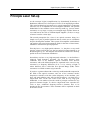
Matisse Reference Cell
The Matisse Reference Cell contains a highly stable, scannable optical
resonator (made of an INVAR rod) serving as an external frequency
reference in different frequency stabilization schemes for the Matisse S
and X models.
The resonator itself is is evacuated. The reasons are:
to prevent humidity-related problems that degrade the piezoelectric
actuator
to minimize the acoustic transmission of noise
to support a better thermalization
Do not open the venting valve!
30
CHAPTER 4
Single-Frequency Tunable Laser Physics
This chapter intends to give a concise and simple introduction into the
physics and technologies used to operate the tunable single-mode
continuous-wave Matisse laser.
Single-Frequency Tunable Laser Physics
31
Principle Laser Set-up
As the acronym L(ight) A(mplification) by S(timulated) E(mission) of
R(adiation) indicates one crucial part of a laser is an amplifying medium.
This (gain) medium has in general to be exited ('pumped') by a adequate
sources to act as an amplifier for electromagnetic radiation. The spectral
bandwidth of a laser medium can be relatively small (e.g. just one atomic
resonance) or very large, covering a wavelength range of under 700 nm to
over 1000 nm in the case of Titanium-doped Sapphire (Ti:Sa) or a range
of some 10 nm for various dyes.
The second prerequisite for a laser is an optical resonator, being in a
simple case a pair of parallel spherical mirrors, which acts as a feedback
loop for the amplifier medium. This system of an amplifier with feedback
can produce self-exited electromagnetic fields in the form of laser beams,
which have well-known special properties.
First they have a very high spatial coherence, i.e., they have a very small
spotsize, when focused, they are the best practical approximation to an
idealized light ray, etc. The simplest laser beam has a transverse intensity
profile in form of a Gaussian distribution.
Second they can have a very high temporal coherence, i.e. the field has a
relatively small frequency spectrum. For the latter property some
conditions have to be fulfilled. Optical resonators have discrete
resonances with well defined frequencies, separated in the case of a ring
resonator by a frequency difference of ∆ν = c/d (c velocity of light, d
mirror distance); this is called the Free Spectral Range (FSR). These
resonances are called resonator (eigen-)modes.
If you have a gain medium with a relatively small bandwidth compared to
the FSR of the optical resonator, and one of the resonator modes'
frequencies coincides with the (center-)frequency of the medium, your
laser will emit radiation only with just this frequency; you then have a
single-mode laser. In the case of the Ti:Sa, with its very large gain
bandwidth, a vast number of modes could in principle oscillate for any
practical resonator length. To achieve single-mode laser operation for
Ti:Sa or dyes, additional frequency-selective elements have to be
introduced into the resonator. These elements will be explained in detail
in the next section.
Single-Frequency Tunable Laser Physics
32
Another important aspect for single-mode laser operations is to choose a
ring-laser geometry instead of a standing wave resonator configuration.
With electromagnetic standing waves, only part of the gain provided by
the laser medium can used by a specific resonator mode; at the locations
of the wave's nodes the gain cannot be depleted ('spatial hole burning'
effect). This can lead to a situation, where another resonator mode,
having its anti-nodes at the locations of the nodes of the former mode,
can start to oscillate and produce a multi-mode laser operation case. Ring
resonators with their running waves do not suffer from this problem, but
there is the possibility for two modes with the same frequency but
running in opposite direction to oscillate. This case produces complicated
intensity dynamics and can be avoided by introducing an unidirectional
device ('optical diode') to allow only modes in one propagation direction
to oscillate.
Apart from adding new elements to the laser another way to reduce the
number of modes is to use resonator mirrors that are highly reflective
only for a certain range of wavelengths. For the Matisse there are five
different optical sets:
Matisse Optical Set
Wavelength Range (nm)
MOS1
690 - 780 (Ti:Sa)
MOS2
750 - 880 (Ti:Sa)
MOS3
850 - 1020 (Ti:Sa)
MOS4
550 - 670 (Dye)
MOS5
650 - 780 (Dye)
(has the same highreflective mirrors as
MOS1, but a different
output coupler)
Single-Frequency Tunable Laser Physics
33
Frequency-Selective Elements
This section gives a description of the frequency-selective optical
elements used in the Matisse. One important parameters of these elements
(except for the Birefringent filter) is the Free-Spectral Range (FSR) as
described above. The FSR of the Matisse ring resonator is about 160
MHz.
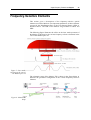
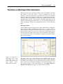
The following figure illustrates the effect on the laser mode spectrum of
the Matisse Ti:Sa-laser by the various frequency-selective elements in the
case of the MOS2 optics set:
Figure 7: Laser mode
spectrum in the case of
the MOS2 optics set
The schematic setup of the Matisse TR is shown in the figure below to
illustrate the geometric arrangement of the various frequency-selective
elements.
Figure 8: Matisse TR
Setup
Single-Frequency Tunable Laser Physics
34
Birefringent Filter
The Birefringent Filter uses the effect of birefringence and the
polarization-selective property of the laser resonator to achieve frequency
selection. It consists of three plates, having thicknesses in the ratio of
1:3:15. For different optics sets Birefringent Filters with different plates
thickness have to be used in general. For MOS-2 the thinnest plate has a
thickness of 280 µm, for MOS-1 and MOS-3 the thickness is 325 µm.
The frequency range, in which lasing modes could exist, is narrowed
down to several 100 GHz by the Birefringent Filter.
This filter serves as the main broad-range tunable element, determining
the (approximate) absolute wavelength, where the Matisse laser will
operate. To achieve single-frequency operation two additional etalons are
necessary as described below.
Thin Etalon
The combination of the Birefringent Filter and the Thick Piezo Etalon is
in general not sufficient to guarantee single-mode single-frequency laser
operation. Therefore there is another frequency filter: a solid state FabryPerot etalon, called the Thin Etalon (TE). Its position in relation to the
laser beam can be adjusted with the help of a motor-controlled mount. It
has an FSR of about 250 GHz (for the standard etalon) and a relatively
small Finesse. The TE is in a way adjusted, that will give no direct
reflections from the etalon's facettes into the laser beam paths to avoid
complicated laser intensity dynamics.
For the TE it also true, that one of its mode's frequency has to be the
same as the laser resonator mode's frequency. For this purpose the
reflection from one facette is monitored and compared to the total laser
intensity. A control loop will adjust the TE position so that the ratio of
these two signals is kept constant.
Single-Frequency Tunable Laser Physics
35
Piezo Etalon Description
The piezo etalon is formed by two prisms with parallel base sides,
functioning as a Fabry-Perot interferometer with an air gap. One prism is
mounted to an piezoelectric actuator to control the air gap thickness. The
free spectral range of the interferometer is about 20 GHz and a Finesse of
about 3.
The piezo etalon ensures that all except one longitudinal mode have so
high losses, that lasing is not possible. Therefore, the spacing of the
etalon must be matched to an multiple of the favored longitudinal mode's
wavelength. Because of the tight spacing and in order to be able to
perform a scan, the spacing is actively controlled. The control loop is
based on a lock-in technique and the etalon spacing is varied by a piezo
drive.
Figure 9: Front view of
the
piezo
etalon
assembly.
1
Prism. The etalon is formed by two prisms. The resonator beam
enters and exits under Brewster's angle.
2 Horizontal Alignment. This screw controls the horizontal tilt of the
entire etalon assembly.
3 Vertical Alignement. This screw control the vertical tilt of the entire
etalon assembly.
4 Piezo Voltage. SMA connector that connects to the piezoelectric
actor.
Single-Frequency Tunable Laser Physics
Figure 10: Side view of
the
piezo
etalon
assembly.
1
36
Horizontal Alignment. This screw controls the horizontal tilt of the
entire etalon assembly.
2 Vertical Alignement. This screw control the vertical tilt of the entire
etalon assembly.
3 Piezo Voltage. SMA connector that connects to the piezoelectric
actor.
4 Vertical Etalon Alignment. This differential-micrometer screw
controls the vertical alignment of the two prisms that form the etalon
to each other.
5 Horizontal Etalon Alignment. This differential-micrometer screw
controls the horizontal alignment of the two prisms that form the
etalon to each other.
6 Prism. The etalon is formed by two prisms. The resonator beam
enters and exits under Brewster's angle.
Single-Frequency Tunable Laser Physics
37
Piezo Etalon Dither
.
Figure 11: Piezo etalon
principle.
Figure 12: PZETL
Phase-Locked-Loop
Principle
Apart from further narrowing down the frequency range of possible laser
modes, the piezo etalon has also to ensure that one of its mode's
frequency coincides with the resonator mode's frequency of the laser.
This is done by modulating the distance between the prisms with the help
of the piezo actuator, so that the frequency spectrum of the etalon is
slightly modulated. This results into a small intensity variation, that is
monitored and used as the input for a control loop, that keeps the center
frequency of the piezo etalon mode at the frequency of the laser resonator
mode. The control loop principle is shown in the following figure:
Having the etalon aligned to the cavity mode is essential not only for
getting the maximum laser power but also in the case of scanning the
laser. Scanning is achieved by changing the laser resonator length
continuously with the help of one of the resonator mirrors mounted on a
piezo actuator. So when the laser frequency changes, the piezo etalon
control loop will make sure that the piezo etalon's mode frequency will
follow, by adapting the thickness of the air gap.
Single-Frequency Tunable Laser Physics
38
Optical Diode (Unidirectional Device)
Because the Matisse is a ring laser, two counter-propagating modes with
the same frequency could co-exist. To prevent this an optical diode is also
part of the optical set-up. It consists of a TGG crystal plate mounted in a
strong magnetic filed, that will rotate the polarization vector of the
electric field by some degrees irrespective of the propagation direction
(Faraday effect). The M3 Matisse mirror of the three-mirror assembly is
an out-of-plane mirror, causing also a rotation of the polarization vector
of the electric field, but this time the direction of the rotation depends on
the propagation direction. For the counter-clockwise running laser mode
the effects of this mirror and the optical diode are canceled out. For the
clockwise running mode the effects sum up, so that this mode will suffer
additional losses at the various Brewster surfaces in the resonator.
39
CHAPTER 5
Frequency Stabilization
For many laser applications is not only necessary to have a singlefrequency laser but also to have a very stable frequency itself, i.e, a small
effective laser linewidth. It is possible to suppress laser intrinsic
frequency noise by using external frequency references. Frequencystabilized Matisse are using highly stable reference resonators, that still
allow to have a scannable laser by scanning the reference in contrast to
using, e.g., atomic frequency standards. There are two stabilization
schemes exploited with the Matisse: for the TS/DS version it is the 'side
of fringe' scheme, for the TX/DX and TX/DX light version it is the
Pound-Drever-Hall method. These two schemes differ in their complexity
and achievable stabilization results as will be described in the following
sections
Frequency Stabilization
40
'Side of Fringe' frequency
stabilization
The concept for this method is relatively simple: when you scan the laser
frequency and observe the transmitted light from the reference cell, you
can observe the well-known Airy-function spectrum of the reference
resonator. The stabilization idea is now to set the frequency of the laser
so that it corresponds to a point of the flank of one of the resonator's
transmission resonances ('side of fringe'). A control loop adapts the laser's
frequency in a way, that keeps the transmitted intensity of the reference
constant. The laser frequency is then locked to one of the reference
resonator's modes.
To achieve this locking a second laser resonator mirror is mounted on a
piezo actuator, the Fast Piezo. This Fast Piezo has to counteract relatively
fast perturbations to reduce the effective laser bandwidth. The former
scan piezo mirror (the Tuning Mirror) in the Matisse TR/DR now
becomes a kind of auxiliary piezo, the so-called Slow Piezo. It has two
tasks to fulfill: first in the not-lcoked case, it will scan the laser to a
resonance of the reference resonator. Second when locking is achieved, it
will keep the Fast Piezo at the center of its dynamics range and so
cancelling out slow drifts of the laser in relation to the reference cell.
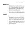
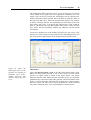
The schematic setup is shown in the following figure:
Figure 13: Matisse TS
Setup
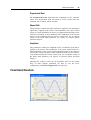
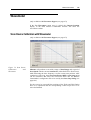
The reference cell in this case is a confocal resonator with a free spectral
range of 600 MHz and a Finesse of about typically 15 to 20. The Airy
Transmission spectrum is shown in the figure below.
Frequency Stabilization
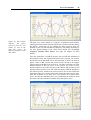
41
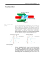
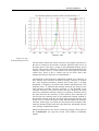
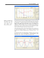
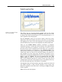
Figure 14: Airy
Transmission Spectrum
The Fast Piezo control loop works as follows: any frequency deviation of
the laser in relation to the reference resonator (shown as blue arrows in
the figure above) will cause a change in the transmitted intensity (green
arrows). This intensity difference to the desired transmitted intensity, the
'setpoint' (in this case 0.5), is then taken as an error signal for the FPZ
control loop. There is also a control loop for the Slow Piezo, that
manages the tasks for this piezo as explained above.
One drawback of this frequency stabilization method is its sensitivity to
laser intensity noise. Because an intensity change is taken as a measure
for a laser frequency deviation, intensity noise of the laser is wrongly
interpreted as frequency deviations and actually transformed into real
frequency noise. To minimize this intensity sensitivity the Finesse of the
used reference resonator could be increased, i.e, the linewidth of the
resonator decreased. This would increase the laser frequency deviation
sensitivity (transmitted intensity change per frequency deviation) and in
this sense decrease the sensitivity to laser intensity noise. But this will
also decrease the catching range of the stabilization method, defined as
the maximal allowed frequency deviation without loosing the laser lock.
In this case it is about one quarter of the full linewidth of the reference
resonator. If this range is too small, the laser lock becomes unstable. This
trade-off situation finally limits the achievable laser bandwidth with the
'side-of-fringe' stabilization scheme.
Detailed instructions for the various control loop settings can be found in
the S Stabilization (see page 88) section of the Matisse Commander
chapter.
Frequency Stabilization
42
Pound-Drever-Hall frequency
stabilization
For the PDH stabilization scheme there are additional elements in the
optical path leading to the reference resonator in comparison to the
Matisse S setup. The schematic setup is shown in the following figure:
Figure 15: Matisse TX
Setup
First of all there are two lenses acting as a telescope to mode-match the
Matisse laser beam to the fundamental mode of the non-confocal
reference resonator.
Then follows an Electro-optical Modulator (EOM) acting as a phasemodulator, which is modulated sinusoidally with a frequency of νmod.
With this modulation the frequency spectrum of the laser beam after the
EOM has now essentially three components: ν0 + νmod, ν0, ν0 - νmod.
Assuming that the reference cell is about resonant with the fundamental
laser frequency ν0 and its finesse is so high that the frequencies ν0 + νmod
and ν0 - νmod. are well outside of the resonator linewidth, only the laser
radiation part with the fundamental frequency can effectively interact
with the resonator, i.e., exciting a field inside the resonator. Part of this
excited field will be coupled out back by the first reference cell mirror.
The sideband parts are effectively just reflected back by the first
reference resonator mirror.
Frequency Stabilization
43
The quantity, that is now observed with a photo diode, is the light
reflected back from the reference resonator. The reflected light is
deflected from the in-going beam path by a combination of a doublypassed quarter-wave plate and a polarizing beam splitter to the Fast
Diode. In general photo diodes act as an intensity detector I = E2 (square
of the electrical field). Having three different frequencies in the spectrum
means, that the resulting diode signal will not only contain a constant
component but also beat signals with frequencies that corresponds to the
various differences of the three optical frequencies. Especially the beat
signals having a carrier frequency of the EOM modulation frequency νmod
are now used for generating a suitable frequency error signal. For that
purpose the diode signal is mixed with the modulation signal for the
EOM, which filters out just the desired signals with the νmod carrier. As a
complication there are actually two signals with this carrier frequency,
but only one of which is usable as an error signal. Fortunately the two
signal have carriers that have a oscillation phase shift of π/2, i.e, they are
mathematically orthogonal like, e.g., a sine and a cosine wave. By
applying a tunable phase-shift to the EOM modulation signal before the
mixer only the desired signal can then be filtered out. The resulting
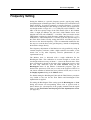
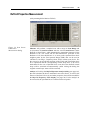
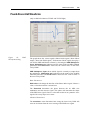
theoretical Pound-Drever-Hall error signal in dependance of the laser
detuning to the used non-confocal resonator with a free spectral range of
1320 MHz and a Finesse of about typically 250 to 300 and a modulation
frequency for the EOM of 20 MHz is shown below.
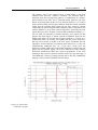
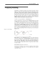
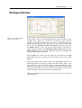
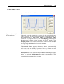
Figure 16: Theoretical
PDH Error Signal
Frequency Stabilization
44
The interesting part of this graph is the relatively steep slope around the
detuning of 0 MHz, giving a very sensitive measure for the laser detuning
in relation to the reference resonator resonance. The fundamental
principle producing this signal form is the following: assuming the laser
frequency is exactly resonant with the reference resonator, then the beat
signal terms of the fundamental frequency with the equidistant 'left'
sideband and the 'right' sideband will cancel out (because the sidebands
have a phase-difference of π), giving a PDH signal of 0. If the laser is
slightly off-resonant, the exited field in the reference resonator will have
an optical phase-shift in comparison to the laser field. The sidebands are
then no longer equidistant in relation to the resonator field frequency (to
be precise you have to look at the optical phases), resulting in non-zero
terms for the PDH signal. The Pound-Drever-Hall method actually
detects optical phase shifts rather than frequency shifts, making it very
sensitive.
The PDH stabilization method is insensitive to laser intensity noise! The
catching range for this method is given by the modulation frequency νmod.
Together this makes the Pound-Drever-Hall stabilization a highly
sophisticated tool for locking schemes.
In the Matisse TX/DX light versions the PDH error signal is used as the
error signal for the Fast Piezo control loop, achieving a significant
improvement in the laser bandwidth in comparison to Matisse S models.
In the full Matisse TX/DX versions, an EOM is added to the laser
resonator, that will also use this signal (after adequate signalconditioning) as the error signal for its control loop. Because the EOM
has a much larger control bandwidth a further significant improvement in
the laser bandwidth can be seen.
Detailed instructions for the various control loop settings can be found in
the X Stabilization (see page 98) section of the Matisse Commander
chapter.
Frequency Stabilization
45
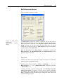
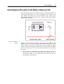
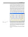
Frequency Drift Compensation
The frequency stabilization schemes described before will give small
laser linewidths, i.e., frequency fluctuations on time scales of several 10
or a few 100 ms are reduced. When you look at the frequency behavior
on time scales of several 10 s or minutes and some hours, the center
frequency of the laser can drift in the order of some 100 MHz, depending
on the ambient conditions of the reference cell environment. The drifts
are due to temperature changes or piezo actuator relaxation processes
acting on the optical properties of the reference cell.
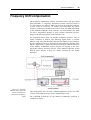
To compensate these drifts, an absolute frequency reference, like an
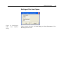
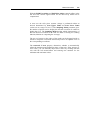
atomic resonance is needed. The following figure shows a possible
Matisse setup, using the absorption/fluorescence signal of a gas exited by
the laser radiation as an error signal for the laser frequency detuning. This
signal is digitized by a DAQ card and processed by a software extension
of the Matisse Commander control program. In reaction to the error
signal this software extension will act via the Matisse controller on the
RefCell piezo actuator to keep the master resonator on the atomic
resonance.
Figure 17: Possible
Matisse Setup using an
atomic resonance to
compensate frequency
drifts
This setup scheme does not need a stabilized Matisse to work. The drifts
of lasers of the Matisse R type can be compensated as well.
The LabVIEW framework for the Matisse Commander extension is
available on request.
Frequency Stabilization
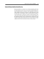
46
Using your own reference for
stabilizing
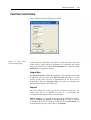
Instead of using the reference cell that comes with the stabilized Matisse
versions, you can also use your own reference, generating an adequate
error signal for the laser frequency deviation. For this the DSP controller
card has an external input for your error signal, so you can take advantage
of the control loop logics already implemented for the Fast and Slow
Piezo. The section DSP Input Characteristics (see page 127) gives the
technical details and constrains for your signal.
When you connect your error signal to the DSP's external input and set
the switch from 'Intern' to 'Extern', you replace the internal error signal
from the Matisse Reference Cell with your own signal. There is exactly
one control loop DSP task, that uses this error signal to act on the Fast
Piezo. So you can either stabilize on your reference or on the Matisse
reference cell, but not on both at the same time.
You have to adapt the Fast Piezo and Slow Piezo control loop parameters
to the characteristics of your error signal.
47
CHAPTER 6
Basic Matisse Operation
The present chapter deals with the standard start-up procedure. This
procedure applies for systems which are well installed, and have been
used under the same operating conditions in the near past. This holds true
if you switch off your system in the evening, and switch it on again the
next morning at the same wavelength.
CW lasers in general are temperature sensitive. Therefore, if the air
conditioning in your laboratory is not running continuously, take care to
switch on the air conditioning and wait for thermal equilibrium before
switching on your laser. The best results will be obtained if your air
conditioning is continuously running, with temperature variations of no
more than +/- 1 K.
Start-Up Matisse-Ti:Sa
1
Switch on your pump laser, and allow for sufficient warm-up time.
Please check your pump laser manual for details about the exact
procedure and the necessary warm-up time. During this time, take
care that the pump beam is blocked before entering the Matisse laser.
If present, use the internal shutter of your pump laser, or any other
suitable external beam dump.
2 In the case of a Matisse TX first switch on the XBox-Controller.
Switch on the Matisse electronics box, and start up the Matisse
Commander program.
3 Place a power meter or any other suitable beam dump at the Matisse
output port.
4 Open the pump laser shutter, or remove the external beam dump, and
apply pump power to the Matisse.
5 Increase the pump power until the Matisse laser threshold is reached.
The energy level necessary for first laser operation depends on the
mirror set and the current wavelength. As a rough indication, if
pumped with a 532 nm beam and used at around 780 nm, the Matisse
should start lasing at about 2.5 - 3 W input power.
6 Slowly increase the pump power up to 5 W. At this pump energy,
most Matisse laser configurations should start lasing. However, for
wavelengths at the edge of the tuning range of the used mirror set, or
at the limit wavelengths of the Ti:Sa crystal itself, even higher pump
power might be necessary. Your Matisse laser should now operate. In
this case, please refer to the next Sections for a quick optimization of
the Matisse output power. If, in contrast, your Matisse laser is not yet
operating, carefully check the entire pump beam path.
Basic Matisse Operation
48
Start-Up Matisse-D
1
Switch on your pump laser, and allow for sufficient warm-up time.
Please check your pump laser manual for details about the exact
procedure and the necessary warm-up time. During this time, take
care that the pump beam is blocked before entering the Matisse laser.
If present, use the internal shutter of your pump laser, or any other
suitable external beam dump.
2 In the case of a Matisse DX first switch on the XBox-Controller.
Switch on the Matisse electronics box, and start up the Matisse
Commander program.
3 Open the Matisse top cover. Place a power meter or any other suitable
beam dump at the Matisse output port.
4 Move the spray guard to its upper position (see Figure below). Verify
that the dye catching tube, situated underneath the dye nozzle, is
centred with respect to the nozzle. If not, slightly move the dye drain,
which should be screwed down to the optical table, to a different
position. In order to avoid the transmission of vibrations to the laser
base plate, the dye catching tube is not screwed to the laser. It is just
squeezed in its holder by some foam. Therefore, moving the dye drain
slightly will allow to re-centre the catching tube with respect to the
nozzle.
Figure 18: View of the
dye jet nozzle and the dye
catching tube. The spray
guard is fixed at its upper
position.
5
6 Set the spray guard back to the lower position (see Figure below).
Basic Matisse Operation
49
Figure 19: View of the
spray guard in its lower
position, to avoid dye
spray during the start up
procedure of the jet.
7
8 On the dye circulator, make sure that the dye by-pass is completely
open. The by-pass is open if the needle valve shown on the next
figure is turned counter-clockwise as far as possible. In this case,
when switching on the dye pump the main fraction of the dye will
follow the by-pass, and no pressure will build up in the circulator
system.
Figure 20: View of the
Matisse dye circulator.
The dye jet pressure
might be varied by
adjusting the needle
valve.
9
10 Switch on the dye pump. The cooling loop in your dye reservoir
should be connected in series to the chiller of the pump laser, and
thus already be operational. If you are using an external cooling
system, then check that this system is operational.
11 Even with the by-pass open, some dye will enter the tube leading to
the dye nozzle. Carefully observe the dye flowing towards the nozzle.
Wait until the dye reaches the nozzle. Once the entire tube from the
circulator to the nozzle is filled with dye, wait for another 5 minutes
before proceeding.
Basic Matisse Operation
50
12 DO NOT open the spray guard to watch the dye arriving in the
nozzle, only check its appearance in the different tubing sections.
13 Slowly close the needle valve on the circulator, in order to increase
the dye pressure. In a first step, only increase the pressure by 1/4 bar.
Wait for 5 minutes. Increase the pressure by another 1/4 bar, wait
another 5 minutes. Continue to increase the pressure in similar steps,
until the pressure reaches 2.5 bar. Wait for 5 minutes. While doing
these steps of increasing pressure, check the dye flow in the drain
back from the dye catching tube towards the pump. Note that the dye
drain is only driven by gravity. If ever you realize that the tube's
position does not allow proper dye flow, e.g., because tube's slope is
not sufficient, then immediately switch off the dye pump and change
the position of the drain. If too much dye accumulates in the tube, and
does not flow back to the pump properly, then in the worst case the
dye may flow backwards out of the dye catching tube in your laser.
14 If the dye flows properly with a pressure of 2.5 bar, then carefully
increase the pressure in one single step up to 4 bar. Wait for 5
minutes, increase the pressure to 6 bar and wait another 5 minutes.
Depending on the type of dye solvent you use, this pressure may
already be sufficient to operate your laser. Furthermore, laser
operation is usually not limited to a single pressure value but is rather
possible in a certain pressure range of up to some bar. If you start
with a new solvent and/or dye you should carry out a series of tests of
laser operation at different pressures to find optimal conditions and
parameters. The aim is to obtain high output power which is as stable
as possible, i.e., there should be no flickering visible within the output
beam. Note that changing the pressure during the adjustment can
slightly alter the shape of the dye jet so you may also have to change
the pumping position and/or the location of the focus with the
pumping mirror (PM) in order to regain optimal laser output. If you
increase the pressure, continue in similar steps as before, i.e., wait 5
minutes after each increase of up to 2 bar. Do not increase the
pressure in bigger steps than 2 bar at once and do not forget to watch
the dye backflow.
15 During the first minutes of operation, characteristic noise from the
nozzle indicates the presence of air bubbles in the dye. If the increase
in pressure is done slowly enough, then the number and size of these
bubbles will be at a minimum. The bubbles will vanish with time.
When the final pressure is reached, do not continue working before at
least 15 minutes of bubble free operation. Bubble free operation
means that you do not hear any gurgling or splashing of dye under the
spray guard.
16 Lift the spray guard to its upper position, and fix it there, as shown in
the first figure. Carefully clean remaining spilled dye with a Q-tip.
Take great care not to cross the dye jet with the Q-tip. Strong dye
spray all over the laser would be the consequence.
17 Set your pump laser to a very low pump power, 0.2 W or less. Open
the pump laser shutter, or remove the external beam dump, and apply
pump power to the Matisse.
18 Make sure that the pump laser is correctly coupled into the dye laser.
Basic Matisse Operation
51
19 Close the Matisse top cover.
20 Increase the pump power until the Matisse laser threshold is reached.
The energy level necessary for the start of laser operation depends on
the used dye and the wavelength. As a rough indication, if pumped
with a 532 nm beam and used with a high gain red dye, the Matisse
should start lasing at about 1.5 W input power.
21 Slowly increase the pump power up to 5 W. At this pump energy,
most pump / Matisse laser configurations should result in an
operating dye laser. However, for very low gain dyes, or at
wavelengths at the edge of the tuning range, even higher pump power
might be necessary. Before further increasing the pump power, please
check again that the pump beam correctly enters the dye laser. Then
slowly increase the pump power until the Matisse starts lasing.
22 Your Matisse dye laser should now operate. In this case, please refer
to the following Sections for a quick optimization of the Matisse
output power. If your Matisse laser is still not operating, then
decrease the pump power to about 5 W, and carefully re-check the
entire pump beam path.
Matisse Power Optimization
Once your Matisse laser is emitting radiation, you should follow the
procedures given below for a fast and easy optimization of the laser ring
cavity and the angular position of the thin etalon and the birefringent
filter. On a daily working routine, this optimization should take only
some minutes, and allow you to fully optimize the laser power.
Before starting the optimization, follow the start-up procedure given
above.
If not yet done, boot the laser control computer and start the Matisse
Commander. Place a power meter in the Matisse beam and monitor the
generated power.
Basic Matisse Operation
52
Cavity Mirror Optimization
The Matisse laser cavity is designed for excellent long term stability.
Therefore, only minor adjustments are necessary to keep the power of
your laser system at maximum level. Once the laser is set up and fixed
with respect to the pump laser only two screws will allow to compensate
the small day-to-day shifts of the laser alignment.
The figure below shows the three off-plane folding mirrors M1, M2, and
M3 in the Matisse cavity. As already mentioned in the Laser Description
Chapter, M1 is the Matisse outcoupling mirror, whereas M3 is equipped
with the fast piezo crystal in case of the actively stabilized models (-TS, TX, -DS, and -DX).
Figure 21: Alignment
screws of the Matisse
three-mirror-set. Screws
S 1v and S 1h allow to
adjust the reflection
direction of Mirror M 1
in the vertical and
horizontal
direction,
respectively. Screws S 3h
and S 3v act similarly on
mirror M3.
The Mirrors M1 and M3 are adjustable even with the top cover of the
Matisse closed, by means of the four tuning knobs shown above.
Knob S 1v tunes mirror M 1 in the vertical sense.
Knob S 1h tunes mirror M 1 in the horizontal sense.
Knob S 3h tunes mirror M 3 in the horizontal sense.
Knob S 3v tunes mirror M 3 in the vertical sense.
For a fast optimization of a laser already running close to its maximum
power, it is sufficient to tune one of the two mirrors M 1 or M 3.
Observe the Matisse power on your power meter. Then, very carefully,
either tune knobs S 1v and S 1h, or tune knobs S 3v and S 3h, in order to
maximize the Matisse power. In general the necessary amount of tuning
will be very small, in the order of a knob rotation of only 1-2 degrees, or
even less. If you turn too far, the Matisse will stop lasing. In this case,
immediately come back to the starting position in order to re-obtain laser
operation, and re-start optimizing.
Basic Matisse Operation
53
Thick Piezo Etalon Optimization
If the cavity mirror optimization does not give you the expected or usual
laser power (within a range of -10 to -15%) for the current wavelength, it
may be necessary to adjust the Piezo Etalon. Before adjusting this etalon
with the help of the two (big) micrometer screws as shown in the Matisse
Ti:Sa Optical Setup (see page 16), note down the current setting using
the scale on the upper side of the two screws. The upper screw
determines the vertical adjustment, the lower one the horizontal one.
Start adjusting the lower (horizontal) screw. Observe the Matisse power
on your power meter. Then, carefully, turn the lower micrometer screw to
maximize the Matisse power. There should be one position where the
laser power peaks. There might be a slight hysteresis, so maximize the
power twice approaching the peaking point from the two different
directions to see which direction gives the maximum power.
Adjusting the upper (vertical) screw can reveal the existence of two
different peaking points having similar laser power (not due to
hysteresis!). Use the one with maximum power. Here also a slight
hysteresis may exist, so apply the same procedure as described above.
If you turn too much, the Matisse will stop lasing. In this case,
immediately come back to the starting position in order to re-obtain laser
operation, and re-start optimizing.
Basic Matisse Operation
54
Thin Etalon and Birefringent Filter Optimization
During laser operation, especially when the laser wavelength is scanned,
the position of the thin etalon is actively controlled by the laser
electronics. The error signal for the electronics it the laser power reflected
from the etalon (as measured by diode D 2), divided by the total laser
power (as measured by diode D 1). This error signal is minimum for the
optimum etalon position. The set-point of the thin etalon and also the
position of the birefringent filter need to be checked and optimized for
each wavelength. Execute the optimization process in the following
order:
Birefringent Filter
Click on Scan in the Birefringent Filter menu of the Matisse Commander
main window. Start a Birefringent Filter scan. A typical result is
displayed in the next figure, where the total laser power (blue curve) and
the Thin Etalon reflection are shown as function of the Birefringent Filter
motor position (in stepper motor steps). The third element in the graph is
a red vertical line ('cursor'), indicating the original motor position before
the scan was executed.
Figure 22: Result of a
Birefringent Filter motor
scan. Blue curve: thin
etalon reflex. Red curve:
total Matisse power.
Both in arbitrary units.
The blue curve has a step function form. Within each step the
Birefringent Filter might be set to an arbitrary position, without changing
the Matisse laser frequency. If you change the motor position from one
step to the next one the Matisse frequency will change normally by one
Free Spectral Range of the Thin Etalon (see the Single-Frequency
Tunable Laser Physics (see page 30) chapter for more details).
Basic Matisse Operation
55
The Birefringent Filter position can be set by moving the red vertical
cursor shown in the graph. Once the acquisition is finished, move the
mouse cursor on the red vertical line, and drag the line by clicking on it
with the left mouse button pressed. Move the filter to about the center of
the step of the blue curve, where the original motor position was located,
so that it coincides with the corresponding local maximum of the total
laser power (red curve), as shown in the figure below. Click on Set in
order to physically move the Birefringent Filter motor. Thus the total
laser power will be optimized, without any influence on the current
wavelength.
You need to hit Set even if the default position of the red cursor is the
position you want to keep, because otherwise the Birefringent Filter will
stay in the utmost right position on the displayed motor position scale.
Figure 23: Move the
Birefringent filter to the
position correspoding to
maximum laser power,
without hopping onto
another step of the blue
curve.
Thin Etalon
Click on Control Position / Scan in the TE (Thin Etalon) menu. Press
Start. The Thin Etalon performs a scan in the vicinity of of its current
position. A typical result is shown in the figure below. The power
reflected from the Thin Etalon and the total laser power are measured
simultaneously as function of the etalon position. The third element in the
graph is a red vertical line (indicating the original motor position before
the scan), which will allow you to move the etalon in a well controlled
way near a minimum of the curve representing the reflected power.
Basic Matisse Operation
Figure 24: This window
indicates the power
reflected from the thin
etalon, as well as the
total laser power, for
different positions of the
thin etalon.
56
The blue curve looks similar to a sequence of parabolas with minima.
Changing the thin etalon's position within such a parabola will not change
the Matisse wavelength. If you change the motor position from one
parabola to the next one the Matisse frequency will change normally by
one Free Spectral Range of the Thick Piezo Etalon (see the SingleFrequency Tunable Laser Physics (see page 30) chapter for more
details).
Once the acquisition is finished, drag the line towards the minimum of
the parabola, where the original thin etalon motor position was located.
Set the line on the left hand side of the minimum, as shown in the next
Figure. Click on Set, and the thin etalon will be moved to the stepper
motor position indicated by the red cursor. You have to hit Set even if the
default position of the red cursor is the position you want to keep,
because otherwise the etalon will stay in the utmost right position on the
displayed motor position scale. The software operates with the gradient of
the reflected power, therefore the cursor needs to be set well outside the
minimum of the curve. On the other hand, setting the etalon too far away
from the minimum of the blue curve will decrease the emitted laser
power, because the minimum of the curve indicating the reflection from
the etalon coincides with the maximum of the laser power curve.
Basic Matisse Operation
57
Figure 25: Drag and
drop the red cursor on
the left hand side of a
minimum of the blue
curve, indicating the
power reflected from the
thin etalon.
When the cursor is properly set to a position corresponding to a reflection
minimum, leave the dialog window by hitting the respective button. In
the Matisse Commander main window click on the TE Control indicator.
The dark green indicator will switch to bright green (as shown below),
indicating that the electronics is now continuously controlling the etalon
position in order to minimize the reflection, and maximize the laser
power. The blue bar underneath the TE Control lamp, labelled TE
Signal, monitors the thin etalon error signal, allowing for a rapid check of
proper etalon operation by just a glimpse.
Figure 26: Main Window
Your laser is now ready to work.
Basic Matisse Operation
58
Frequency Setting
Setting the Matisse to a specific frequency needs a step-by-step setting
and optimization of Birefringent Filter, Thin Etalon (TE) and Thick Piezo
Etalon (PZETL). In order to approach a specific frequency f, you first
need to set the Birefringent Filter. Doing so will allow you to set the laser
wavelength within a range of f +/- 0.5 × FSR(TE), where FSR(TE) = 250
GHz is the free spectral range of the Thin Etalon (This is the standard
value, it might be different for your laser. Older Matisse lasers were
shipped with a TE with a FSR(TE) = 130 GHz). Then you need to set the
Thin Etalon, resulting in a laser frequency within the range of f +/- 0.5 ×
FSR(PZETL), where FSR(PZETL) = 20 GHz is the free spectral range of
the Thick Piezo Etalon. Finally, tuning the PZETL will allow you to set
the laser to the desired frequency f. The recommended method for this
last step is to scan the laser to the goal frequency, instead of manipulating
the baseline voltage directly.
Fine frequency adjustments of the Matisse are only possible by using an
external frequency reference, either a high resolution wavemeter, or the
atomic line or any other frequency selective phenomenon of your
experimental set-up.
The Matisse laser is delivered with a rough calibration for the
Birefringent Filter. This calibration is accurate enough to set the laser
wavelength with an accuracy of about +/- 1 nm to the desired value. If the
laser wavelength is already in the range of the calibration accuracy, skip
the next step. Otherwise open the Goto Position dialog in the
Birefringent menu of the Matisse Commander program. Type the
desired laser position (in THz, nm, or 1/cm) in the respective field. You
can choose whether to indicate the laser position in THz, nm, or 1/cm in
the Display Options dialog in the Matisse menu.
For further tuning the Birefringent Filter and the Thin Etalon a procedure
very similar to the one for the Thin Etalon and Birefringent Filter
Optimization is applied.
For tuning the Birefringent Filter setting open the Birefringent => Scan
dialog and execute an corresponding motor scan. A typical result is
shown below (for a description of the graph's elements and the signal
forms see the Thin Etalon and Birefringent Filter Optimization section
(see page 54))
Basic Matisse Operation
Figure 27: Result of a
Birefringent Filter motor
scan. Blue curve: thin
etalon reflex. Red curve:
total Matisse power.
Both in arbitrary units.
59
Press Set and note down the wavelength/ frequency. Now move the (red)
cursor to the center of the next step of the Thin Etalon reflex signal and
press Set again. A comparison between the current and former frequency
should reveal a difference with an absolute value of one FSR(TE). The
change in frequency going from step to step in one direction is
monotonous. So what you have to do is to find the direction and motor
position range (step), in which the absolute value of difference between
current and desired frequency decreases and gets minimal.
This positioning procedure of the Birefringent Filter motor will allow you
to set the laser within the range of +/- 0.5 × FSR(TE) around the desired
frequency (for a standard configuration this corresponds to about +/- 125
GHz).
The tuning procedure for the Thin Etalon is analogous to the one for the
Birefringent Filter. Open the Thin Etalon => Control Position / Scan
dialog and execute a motor scan resulting in the figure below.
Basic Matisse Operation
Figure 28: This window
indicates the power
reflected from the thin
etalon, as well as the
total laser power, for
different positions of the
thin etalon.
60
Press Set and note down the wavelength/ frequency. Now move the (red)
cursor to the minimum of the next parabola of the Thin Etalon reflex
signal and press Set again. A comparison between the current and former
frequency will normally reveal a difference with an absolute value of one
FSR(PZETL). The change in frequency going from parabola to parabola
in one direction is not necessarily monotonous. There can be differences
of up to one FSR(TE). Finding a parabola by going from one to the next
one, that has a minimal absolute value for the frequency difference is here
the goal.
It should be possible to approach the desired frequency within a range of
+/- 0.5 × FSR(PZETL) (for a standard configuration this corresponds to
about +/- 10 GHz). If you cannot get close to this value, please have a
look at the full range of TE motor positions, where there is a TE reflex
signal and try to find a parabola with a frequency difference in the stated
range.
Before doing the final approach to your frequency f, you have to optimize
the position of first the Birefringent Filter, and then the Thin Etalon, as
described in the Thin Etalon and Birefringent Filter Optimization
section (see page 54). Finally scan the laser to the desired frequency (see
the following section).
In most cases, the procedure described above allows a direct approach to
the selected frequency. In some cases, however, the interaction of
Birefringent Filter, Thin and Piezo Etalon leads to an unstable optics
configuration. In this case, more stable operation can be achieved by
tuning the Birefringent Filter and Thin Etalon settings described above
more than once.
Basic Matisse Operation
61
Frequency Scanning
The Matisse is scanned by acting on the logical scan piezo. For the
Matisse R version this is the long-travel piezo the tuning mirror TM is
mounted on, for the stabilized Matisse versions this is the reference cell
piezo. Before starting a scan, you need to optimize the Birefringent filter,
the Thin and the Thick Piezo Etalons at the scan reference frequency as
described in previous sections. Take care to activate automatic tuning of
the Thin and Thick Piezo Etalons by clicking on TE Control and
PZETL Control and additionally for the stabilized versions to enable the
reference cell lock in the Matisse Commander window.
To define a scan open the Scan => Scan Setup menu.
Figure 29: Scan Timing.
Scans are defined by the current Scan Piezo Position, Start (lower limit)
and Stop (upper limit) positions, that have a nominal voltage range of 0
to .65. Set the voltage applied to the scan piezo and the upper and lower
limits of the scan, respectively. The value written in the Position field
when opening the Scan Setup represents the current voltage on the
scanning piezo, which is driving the scan piezo. If you set the laser to a
specific position (e.g. the start frequency of the scan to be performed)
prior to opening the Scan Setup menu, then you can easily deduce the
piezo voltage corresponding to this laser frequency just by checking the
Position value.
Rising Speed (V/s) and Falling Speed (V/s) are the voltage change per
second (see diagram above). Scan Stop Mode determines if and when
the scan stops (at upper or lower limit). There are eight pre-defined scan
modes: first you may choose if the scan starts with increasing or
decreasing voltage. Additionally, you may choose if the scan stops once it
arrives at the upper voltage limit, the lower voltage limit, either of them,
or neither of them.
Scan Control switches the scan off or on.
Once the scan is defined it can be started or stopped by simply clicking
on Scanning in the Scan menu, or on the Scan LED in the Matisse
Commander window.
Basic Matisse Operation
62
Shut-Down Matisse-T
1
Switch off the pump laser.
2 Exit the Matisse Commander.
3 Switch off the Matisse electronics box and in the case of a Matisse X
also the XBox-controller
Shut-Down Matisse-D
1
Switch off the pump laser.
2 Open the Matisse top cover.
3 Loosen the fixing screw of the spray guard and move the guard to its
lowest position. The dye jet should be completely hidden inside the
spray guard.
4 Open the needle valve on the dye circulator. The dye will no longer
flow to the sapphire nozzle, but follow the bye-pass. Decrease the
pressure until, the dye jet starts to contract itself to a V-shape form.
The indicated pressure is not 0!
5 Switch off the dye circulator.
6 Close the laser cover.
7 Exit the Matisse Commander.
8 Switch off the Matisse electronics box and in the case of a Matisse X
also the XBox-controller.
63
CHAPTER 7
Matisse Commander
Installation
The Matisse Commander program runs on Windows 2000, Windows XP
and Windows Vista (32 and 64 bit versions). Installing the program
requires Administrator privileges. A USB port is needed to connect the
laser to the PC.
First install the software by executing setup.exe in the Matisse
Commander Installer subdirectory, then connect the laser to the
computer. Windows should detect the new device and ask for a driver.
Let Windows execute an automatic search.
The Matisse Commander is based on LabVIEW 8.6, for device
communications National Instruments' VISA software is used.
Corresponding required software (LabVIEW runtime 8.6, VISA runtime
4.3 or higher, etc.) will be installed or updated during the Matisse
Commander installation, if no appropriate software is already present on
the computer.
Version Changes
Matisse Commander 1.6
Matisse Commander 1.6.x rescales parameters with small values (<< 1)
by a factor of 10000. This is true for the FPZ and SPZ control loop gain
parameters as well as for the PZETL modulation amplitude. These
parameters are rescaled only for display purposes. The internally used
values in the Matisse Controller stay the same!
Matisse Commander
64
Matisse Commander 1.8
Version 1.8 is based on LabVIEW 8.6. The dialog window for the piezo
etalon was re-programmed to accommodate the new feed-forward
parameters and to clarify the usage of the control. The fast piezo dialog
was modified to reflect the changes in the firmware.
General
With the help of the Matisse Commander program you can manipulate
the positions of the frequency selective elements and the settings of
control loops, respectively, to achieve maximal, stable single-mode
output from the Matisse laser device. Moreover this program allows you
to configure and execute scans over the laser's wavelength.
The following chapters, ordered in analogy to the menu structure of the
program, gives you information on the various functions of Matisse
Commander. References to indicators or controls of dialogs are set in
bold type.
The following subsections provides information concerning Matisse
Commander in general.
Matisse Commander
65
Start-Up
At the start-up of the program, Matisse Commander will try to detect the
presence of a Matisse laser device, either with the help of information in
the Matisse Commander's configuration file 'Matisse Commander.ini' or
by directly accessing USB devices, that have the correct Manufacturer
and Model ID. If no Matisse laser can be located, the following dialog
will appear, requesting you to power-up the Matisse controller box and
restarting Matisse Commander or to choose the Dummy Mode.
Figure 30: Device Not
Found dialog
The Dummy Mode is useful for getting familiar with the control program
without needing an actual physical device or using it as a test
environment for software plug-ins for the Matisse Commander (see the
'Matisse Programmer's Guide' for further details). This mode tries to
simulate the Matisse controller box with an idealized laser, but it does not
completely implement all device commands, so you might encounter
error messages in some dialogs.
Matisse Commander
66
Error Dialog
Figure 31: Error Dialog
If an error occurs, this dialog will display basic error information. Details
will provide more information. Display Off will switch off the controls
on the Main Window (see page 68). This may be helpful if the error
occurs repeatedly in the data gathering loop for the various indicators.
You can switch on the display again in the Display Options dialog (see
page 76). You have to choose, if you wish to Continue with the
application execution or if you want to Exit Matisse Commander.
Key Navigation
Matisse Commander and all its dialogs follow a key navigation standard:
Key(s)
Function
<Enter>
Execute Function, Change Settings
<Esc>
Abort Dialog, Function
F1
Show context-sensitive Help
F2
Open Dialog Options
Matisse Commander
67
Wavemeter Support
The functionality of the Matisse Commander software can be enhanced
by using devices capable of measuring the laser's current wavelength
(further referred to as 'wavemeters'). New functions like a 'Goto
Wavelength' routine, that sets the laser to any desired wavelength
position within its tuning range, could be implemented.
Wavemeter support for the Matisse Commander program, which is
developed with LabVIEW, is achieved by using LabVIEW application
libraries ('plug-ins') for different kinds of wavemeters, that conform to a
specific interface. Further details are given in the 'Matisse Programmer's
Guide'
available
on
the
Sirah
website
www.sirah.com
http://www.sirah.com.
Firmware Update
The firmware of the hardware controller can be updated via the Firmware
Updater program available on the Sirah website http://www.sirah.com
http://www.sirah.com
Matisse Commander
68
Main Window
Figure 32: Main Window
The window contains an indicator for the Current Position of the laser
(Display Options dialog (see page 76)) and a time chart of the total Laser
Power. Clear Chart will erase the time chart history. Thin Etalon and
Piezo Etalon Control are simultaneous indicator/control displays,
determining the status of the corresponding control loops for the Thin and
the Piezo-Etalon. Thin Etalon Signal displays the Thin Etalon reflex
signal and the Piezo Etalon Baseline indicator/control gives the voltage
baseline applied to the piezo element. If this voltage exceeds critical
values, the numerical indicator will start blinking red. In this case, use the
slider to reset value. Changing this value might cause a shift in the laser
frequency! The Scan indicator/control displays the current scan status
and there is also the Scan Piezo Voltage shown. With the Direction
indicator/control the scan direction (up or down) can be quickly toggled.
For Matisse models TS or higher the main window contains also the
Stabilization indicator/control display, with which you can turn on or off
the locking of the laser to the reference cavity. For this control loop the
voltage applied to the slow piezo, given by the Slow Piezo Voltage
indicator/control, is of importance. It should not exceed critical values: if
the slider is at the limits of the control, use the slider to reset the value.
The Laser Locked indicator/control indicates if the locking state is
reached and maintained. Clicking on it will toggle the Stabilization state.
Matisse Commander
69
Matisse (Tools and Options)
Device Configuration
Figure
33:
Device
Configuration Menu
A device configuration comprises the various parameters for the control
loops, the Birefringent Filter calibration parameters, the scan setup, the
switch-off level, etc., that are stored on the Matisse DSP controller board.
Two different kinds of configurations are available: Factory and User
configurations. Factory configurations are preset and can not be changed.
It is possible to have several user configurations that can be newly
created, changed and saved. There is a default configuration that is used
at every start-up of the Matisse controller. To fully administer the various
device configurations see Device Configuration Administration (see
page 70). This menu lets you make the active configuration the default
one, save the active configuration to the Matisse DSP board or to a
human readable text file. Also you can load configurations from a file.
Note: Saving the active configuration will interrupt the execution of the
Thick Piezo Etalon control loop!
Matisse Commander
70
Device Configuration Administration
Figure
34:
Device
Configuration
Administration dialog
The Device Configurations control lists all available configurations,
differentiated by Factory and User configurations (for a description what
'configuration' means, see Device Configurations (see page 69))
There is also the Active and the Default Configuration displayed. With
Activate or Make Default you can give any of the available
configurations the corresponding status. Only User Configurations can be
saved, deleted or newly created.
Active -> File will save the active configuration to a text file, File ->
Active will load a configuration from such a file.
Note: Listing the various configurations, saving or creating a
configuration will interrupt the execution of the Thick Piezo Etalon
control loop
Matisse Commander
71
Advanced Options & Tools
Interactive Shell
Figure 35: Interactive
Command Shell
You can directly communicate with the laser device using low-level
device commands.
Commands typed into the Command control, followed by pressing
<Enter>, will be sent to the Matisse controller and executed. The
controller's response will be shown in the Response indicator. A history
of sent commands to choose from can be accessed by using the pull-down
menu of the Command control. To send the current command repeatedly
you have to press Send Again. You can also arrange commands line-wise
in a text file and load this file via Batch File. The text lines will be sent
until an 'End Of File' or the word 'END' is encountered.
Matisse Commander
72
Thin Etalon Signal Monitor
Figure 36: TE Signal
display
The Thin Etalon's reflex signal is displayed to be used when adjusting the
reflex on the corresponding detector.
Integrate Wavemeter
Figure 37: Wavemeter
Integration dialog
If you have a wavelength measuring device (wavemeter) available, the
functionality of the Matisse Commander can be enhanced provided that a
corresponding software plug-in can be created. Further information
concerning the software plug-in can be found in the 'Matisse
Programmer's Guide'.
Remove Wavemeter
Figure 38: Wavemeter
Removal
The integrated support for a wavemeter (Integrate Wavemeter (see page
72)) will be removed, i.e., the Matisse Commander program will not
search for wavemeter plug-ins at the start-up.
Matisse Commander
73
Control Loop Live View
Figure 39: Control Loop
Live View Dialog
This dialog lets you view the internal variables used by the various
control loops (Process, Controller and Setpoint value) and can be used
to optimize the control loop parameters. It is a non-modal window, i.e., it
runs in parallel to the main program.
From the Protocol control you can choose which control loop (none,
Thin Etalon, Thick Piezo Etalon, Slow Piezo, Fast Piezo) is to be logged.
The logging process uses a 256 value ring buffer to record the data. If the
selected control loop is not active the ring buffer may hold random data.
There are two Sample Modes available: Continuous or Snapshot.
Continuous will give a steady data stream. Because of the different time
scales the control loops are working on, you may have a real live view for
the slower loops or just a sampling view for the faster ones. An indicator
which kind of behavior you experience is the Ordinal Number. If it
stays the same all the time or increase only slightly over time, the current
control loop values are read out; if it increases rapidly, you only have a
time sampled view of the control loop. The debug view behavior can be
influenced by changing the Period time interval, with which the logging
buffer is read out. Options will open the Control Loop Live View
Options dialog (see page 74), where the default values for the period
times can be changed. Choosing too small a period value may lead to
communication errors due to the parallel access to the Matisse device by
the status data gathering loop of the Matisse Commander.
The Snapshot mode will wait until the ring buffer contains new data and
will display therefore a fully real-time snapshot of the control loop
behaviour, regardless of the time-scale it it working on. Snap will trigger
another snapshot.
Clear will erase the data displays.
Matisse Commander
74
Control Loop Live View Options
These controls determine the delay time for the continuous read-out of
the various control loops' data in the Control Loop Live View dialog (see
page 73).
Device Hardware Configuration
Figure 40: Hardware
Configuration dialog
The various Matisse models possess different (electronic) hardware
components. In this dialog you can activate or deactivate these
components. To make this change permanent you have save the active
configuration (see Device Configuration (see page 69)). Changes will
come into effect at the next start of the Matisse hardware controller.
Control Switch-Off Level
Figure 41: Switch-Off
Level dialog
The Switch-Off Level is the total laser power level, below which the
control loops are deactivated.
Matisse Commander
75
Powermeter
Figure 42: Powermeter
The powermeter displays the total laser power and can be used for
adjusting purposes.
Motor Status
Figure 43: Motor Status
Display
This windows display the current position and status of both the Thin
Etalon and the Birefringent Filter motors. It is updated every 500 ms and
runs in parallel to the main program.
Show/Clear Error will show you an error dialog indicating which motor
error occurred and clear the error status, if the Thin Etalon or the
Birefringent Filter motor controller are in an error condition
Matisse Commander
76
Display Options
Figure
44:
Options dialog
Display
The Position Display Mode control determines the physical unit the
program uses to display the position of the laser device. Precision sets
the number of digits to be shown after the decimal point. It has only an
effect,if a wavemeter is used, otherwise the precision is fixed to one digit.
Display On switches the controls and indicators in the Main Window
(see page 68) on or off.
Birefringent Filter
Goto Birefringent Filter Position
Figure 45: Birefringent
Filter Goto Dialog
In this dialog you can move the laser to a new position in units
determined by the Display Options (see page 76). The position of the
Birefringent Filter motor position is computed with the help of a
calibration function, the parameters of which can be calculated in the
Birefringent Filter Calibration Table (see page 79).
Matisse Commander
77
Birefringent Filter Scan
Figure 46: Birefringent
Filter Scan dialog
In this dialog a scan over the Birefringent Filter motor positions can be
executed. Two signals are recorded: the total laser power and the
intensity of the thin etalon's reflex. The scan is centered around the
current Birefringent Filter motor position. The scan range and increment
can be set in the Birefringent Filter Scan Options (see page 78) (press
the Options button or F2). The current motor position is shown as a
cursor (vertical red line) in the Birefringent Filter Scan graph and in the
Motor Position control. You can change this position by changing the
position control and pressing Goto.
Pressing Start will execute the scan, that can be aborted by the Stop
button. Set will move the motor to the position the cursor in the graph
points to.
Achieving maximal laser output requires the Birefringent Filter to be
positioned optimal in relation to the thin and thick etalon. After a scan
you should see a curve for the thin etalon's reflex, that looks like a step
function. Set the graph's cursor by dragging it with the left-mouse button
pressed about into the center of such a step, so the position coincides with
a local maximum of the total laser power, and press Set.
If Set is not used the motor will stay in the scan's end position, when you
close the dialog!
Matisse Commander
78
Birefringent Filter Scan Options
Figure 47: Birefringent
Filter Scan Options
dialog
These controls determine the Scan Range and Scan Increment of the
Birefringent Filter Scan.
Matisse Commander
79
Birefringent Filter Calibration Table
Figure 48: Birefringent
Filter Calibration Table
Editor
The laser's wavelength can be calculated to an accuracy of +/- 1 nm if
there is an adequate calibration function for the Birefringent Filter motor
positions. The calibration table represents the relationship between
wavelengths and motor positions, that will be used to calculate a
corresponding function. To get data, set the laser to a known wavelength
and enter it into the table. Get MOTBI Pos will retrieve the current
MOTBI position and fill it into the active row (Click into a row, to make
it the active one). Sort will sort the table row in descending order of the
wavelengths. You can Delete marked rows. Mark rows by selecting them
with the left mouse-button pressed.
With Open File, Save, Save As... you can open or save files containing
calibration table data.
Fit will fit the table data to the calibration function:
Wavelength = WLOff + WLFac*sin^2 [ arctan (LLen*( pos + LOff)) ]
Matisse Commander
80
The Coefficients have to fulfill certain conditions. WavelengthOffset
(WLOff) has to be greater than the maximum wavelength occurring in
the table. WavelengthFactor (WLFac) has to be negative. Good start
values might be (maximum wavelength in table + 50) for
WavelengthOffset, -400 for WavelengthFactor, 2e-6 for LeverLength
(LLen) and 100000 for LinearOffset (LOff).
On opening the Calibration Table dialog the Coefficients indicator gives
the current function parameters (WLOff, WLFac, LevLen, LinOff) used
by the Matisse controller. After a fit is executed it will contain the newly
calculated numbers together with the Maximum Deviation and the
Mean Deviation of the fit result. If Show Graph is ticked a graphical
representation of the fit result and its errors is shown, after a fit has been
executed.
Set CalPar will program the displayed Coefficients into the Matisse
controller. To make this change permanent you have to save the active
configuration (see Device Configuration (see page 69)).
available only with wavemeter support:
Birefr. Scan will open the Birefringent Filter Calibration Table: Birefr.
Filter Scan (see page 80) dialog, where a scan over the Birefringent
Filter motor positions is executed, simultaneously measuring the
wavelength with the help of an external wavemeter.
Birefringent Filter Calibration Table: Birefr. Filter Scan
(only available with wavemeter support)
In this dialog a scan over the Birefringent Filter motor positions can be
executed, while simultaneously measuring the current wavelength with
the help of an external wavemeter. The scan start and end positions and
increment can be set in the Birefringent Filter Calibration Table: Birefr.
Filter Scan Options (on page 80) (press the Options button or F2). The
range of motor position that is imported into the Calibration Table (see
page 79) is determined by the two red cursor (vertical red line) in the
Birefringent Filter Scan graph. Change this range by dragging the
cursors to other positions.
Pressing Start will execute the scan, that can be aborted by the Stop
button
Birefringent Filter Calibration Table: Birefr. Filter Scan Options
(only available with wavemeter support)
These controls determine the Scan Start, Scan Start and Scan
Increment of the Birefringent Filter Calibration Table: Birefr. Filter
Scan (see page 80).
Matisse Commander
81
Thin Etalon
Thin Etalon Control Setup
Figure 49: TE Control
Setup dialog
In this dialog you can determine the behavior of the Thin Etalon control
loop by setting the loop's parameters, like the Proportional Gain,
Integral Gain and Average, which is the number of measurements the
loop is averaging to compute the error signal. Thin Etalon Control will
switch the control loop on or off.
Flank Orientation determines on which flank of the Thin Etalon
parabola structure in the Thin Etalon Scan (see page 82) the laser is
stabilized
Gain Parameter Scaling? enables the linear scaling of the two control
loop gain parameters with the control loop setpoint, set with the Thin
Etalon Scan (see page 82) procedure.
Changing the controls' values has an immediate effect on the control
loop.
Matisse Commander
82
Thin Etalon Scan
Figure 50: TE Control
Position dialog
In this dialog a scan over the Thin Etalon motor positions can be executed
to set the control position for the Thin Etalon control loop. Two signals
are recorded: the total laser power and the intensity of the thin etalon's
reflex. The scan is centered around the current TE motor position. The
scan range, scan increment and the initial motor position can be set in the
Thin Etalon Control Position Options (see page 83) (press the Options
button or F2). The current motor position is shown as a cursor (red line
within the graph) in the Thin Etalon Scan graph and in the Motor
Position control. You can change this position by changing the position
control and pressing Goto.
Pressing Start will execute the scan, that can be aborted by the Stop
button. Set will move the motor to the position the cursor in the graph
points to and the control goal value will be set. (It is the ratio of the thin
etalon's reflex and the total power at that position).
For keeping the Thin Etalon synchronized with the movements of the
Piezo Etalon the reflection from one etalon facette is monitored and
compared to the total laser intensity. The TE control loop will adjust the
TE position so that the ratio of these two signals is kept constant.
Choosing the right control point is important for achieving stable
modehop-free single-mode operation of the laser. After a scan you should
see a curve for the thin etalon reflex, that consist of a succession of
parabolas with minima. Set the cursor by dragging it with the left-mouse
button pressed on the left flank of a parabola close to its minimum and
press Set, if Flank Orientation is selected to be 'Left'. Set the cursor by
dragging it with the left-mouse button pressed on the right flank of a
parabola close to its minimum and press Set, if Flank Orientation is
selected to be 'Right'.
Matisse Commander
83
If Set is not used, the motor will stay in the scan's end position, when you
close the dialog!
Thin Etalon Control Position Options
Figure 51: TE Control
Position Options dialog
These controls determine the Scan Range and Scan Increment of the TE
Control Position setting procedure.
The Initial Motor Position is the position the TE motor is moved to,
when you call the TE Control Goal dialog. If it is set to a negative
number, the motor will not not be moved.
Piezo Etalon
The thick piezo-etalon ensures that all except one longitudinal mode have
so high losses, that laser emission is not possible. Therefore, the spacing
of the etalon must be matched to an multiple of the favored longitudinal
mode's wavelength. Because of the tight spacing and in order to be able
to perform a scan, the spacing is actively controlled. The control loop is
based on a lock-in technique and the etalon spacing is varied by a piezo
drive.
The lock-in measures the response of the laser to an externally introduced
perturbation. The perturbation is a slight modulation of the etalon
spacing. The modulation follows the amplitude of a sine wave with a
modulation frequency f_mod. The response of the laser is the variation in
the total laser power, measured at the power diode.
Matisse Commander
84
Piezo Etalon Control Setup
Figure 52: Basic setup
for piezo etalon.
This dialog has two tabs Basic and Advanced.
Amplitude
This parameter controls the amplitude of the sine modulation that is
applied to the piezoelectric actor. The value for the Amplitude should
never exceed 50. Depending on the actual etalon values between 5 and 25
should work for almost all cases. Bigger values make for a 'cleaner'
waveform (less amplitude noise), but might decrease the power output of
the laser. Too big values for the Amplitude will show up as more than
one mode per FSR in the monitor spectrum.
Phase Shift
This parameter controls the phase shift that is applied before the
convolution of modulation waveform and waveform detected at the
integral diode is calculated. You should find a range of values (or just one
value), where for each value the Piezo Etalon Waveform is stationary,
i.e., its form stays the same apart from some amplitude noise. Choose a
value from the center of the range. Note: The Phaseshift parameter can
only be changed in discrete steps of (180° / oversampling points).
Control Loop Active?
This button controls if the action that is calculated by the control loop is
applied to the piezo. If the control loop is inactive the modulation is still
applied.
Waveform
This button opens the Piezo Etalon Waveform (see page 86) window.
Matisse Commander
85
Advanced Settings:
Figure 53: Advanced tab
of the piezo etalon
control dialog.
The advanced tab is divided into three sections, each section controls a
different aspect of the piezo etalon. Oversampling and Sample Rate
control the modulation frequency, Average and Proportional Gain
control the action of the control loop, Phase Shift and Amplitude the
action of the feed forward to the tweeter.
Oversampling
This parameter determines how many samples are used to synthesize the
modulation waveform. The minimum value is 8, the maximum value is
64 samples per period.
Sample Rate
This parameter determines the rate at which each of the sample points is
transferred to the piezo etalon. The combination of Oversampling and
Sample Rate determines the frequency of the modulation: f_mod =
Sample Rate / Oversampling. Valid Sample Rates are 8 kHz, 32 kHz, 48
kHz, 96 kHz. Hence, the limits for the modulation frequency are 125 Hz
and 12 kHz.
Frequency (Output)
Displays the calculated modulation frequency for the selected
combination of Sample Rate and Oversampling.
Average
This parameter determines how many cycles of the modulation are
averaged before the controller action is calculated. An increase in the
number of averaged cycles lead to a betters signal-to-noise ratio of the
control signal but makes the control loop less responsive.
Matisse Commander
86
Proportional Gain
The Proportional Gain determines the magnitude of the controller
action. Low Proportional Gain will result in a slow reaction from the
controller, but overshoot will be avoided.
Phase Shift
This parameters controls the phase shift that is applied to the modulation
signal that is applied to the tweeter. The modulation of the piezo etalon
results in a small modulation of the cavity length and subsequently of the
emission wavelength. A direct feedback of the modulation to the tweeter
removes some workload from the tweeter control loop. For an optimal
setting of the Phase Shift parameter you require an external optical
spectrum analyser.
Amplitude
This parameters controls the amplitude of the modulation signal that is
applied to the tweeter. The modulation of the piezo etalon results in a
small modulation of the cavity length and subsequently of the emission
wavelength. A direct feedback of the modulation to the tweeter removes
some workload from the tweeter control loop. For an optimal setting of
the Phase Shift parameter you require an external optical spectrum
analyser.
Changing the controls' values has an immediate effect on the control
loop. To make changes permanent you have to save the active
configuration (see Device Configuration (see page 69)).
Piezo Etalon Waveform
Matisse Commander
87
The graph shows the AC-part of the total laser power. The curve should
be stationary, when the Piezo Etalon control loop is on, and should have a
sine-like (w-shaped), harmonic form starting with a maximum.
Matisse Commander
88
S Stabilization
(only available for Matisse TS/DS)
The Matisse laser frequency can be stabilized by locking the frequency to
a mode of an external reference resonator (using the 'side-of-fringe
locking technique). Pertubations that might destroy this lock are
counteracted by an actively controlled laser cavity mirror mounted on a
fast piezo actuator (FPZ). An actively controlled slow piezo (SPZ) acting
on another laser mirror ensures that the FPZ will always have its full
dynamical range to react on pertubations.
How to lock the Laser:
open the RefCell Waveform (see page 93) display and set Scan
Upper Limit to 0.1, Scan Lower Limit to 0, Oversampling to 128
and Sampling Mode to 'Average'. Optimize the adjustment of the
laser beam into thee reference resonator. The photo diode signal for
the transmitted light has a nominal value range from about -0.2 to 0.4.
The signal maximum value should be lower than 0.25. Adapt the
filters accordingly.
open the Fast Piezo Control Setup (see page 90) dialog, set the
Setpoint to a value about half of the maximum peak signal seen in
the Waveform display.
make sure the slow piezo baseline is in the middle of its range.
activate the lock by clicking on the RefCell Control LED indicator in
the main window or ticking the 'Control On' item in the RefCell
Stabilization menu
Troubleshooting
If no lock can be obtained, stop the RefCell Control loop. Open 'Matisse'
-> 'Advanced Tools & Options' -> 'Control Loop Live View'. Set
Protocol to 'FPZ'. The upper graph in this case will show the photo diode
signal, the red line corresponds to the FPZ Lockpoint. Let this window
open and switch on the RefCell Control loop. Observe now the upper
graph. When you switch on the control loop and there is no lock, then the
slow piezo starts scanning the laser to find a resonance of the reference
resonator. You should see after a while in the upper graph the peaks of
the resonator spectrum appear. If you cannot see, that the FPZ lock is
setting in, then you should decrease the Free Proportional Gain
parameter in the Slow Piezo Control Setup (see page 92) dialog. This
parameter determines the scan speed of the slow piezo.
If you see that the fast piezo control loop tries to lock to the setpoint, but
looses the lock quickly, than you have to increase the fast piezo control
loop parameters in the Fast Piezo Control Setup (see page 90) (e.g.
multiply the values by a factor of 2).
Optimizing the lock
Matisse Commander
89
open the RefCell Properties Measurement dialog (see page 95).
Measure the spectrum and choose about half of the maximum peak
signal seen in the spectrum graph as the new Setpoint for the fast
piezo control loop.
open the Frequency Noise display.
increase the Integral Gain for the fast piezo control loop (multiply
by factors of 2) until you see an increase in the displayed frequency
noise. There is a threshold for this parameter, above which the control
loop starts to oscillate and frequency noise rises strongly. Decrease
the Integral Gain until you find this threshold value. Choose a value
that is about 10% smaller than the threshold value. If you cannot find
a threshold you might have already started above it, so decrease the
Integral Gain until you will find a decrease in the frequency noise.
Matisse Commander
90
Fast Piezo Control Setup
(only available for Matisse TS/DS and TX/DX)
Figure 54: Fast Piezo
Control Setup dialog
In this dialog you determine the behavior of the Fast Piezo (Tweeter)
control loop by setting the loop's parameters. For optimizing the control
loop's gain parameters see either the S Stabilization (see page 88) and X
Stabilization (see page 98) sections.
Integral Gain
The Integral Gain determines the magnitude of the controller action that
is applied to the fast piezo. Low Integral Gain will result in a slow
reaction of the piezo and not all perturbations of the laser will be
compensated. Excessive Integral Gain will result in overshoot and
uncontrolled oscillations of the fast piezo.
Setpoint
This value defines the control goal for the fast piezo control loop. The
control loop will try to stabilize the laser at a wavelength that
corresponds to the Setpoint value at the DSP input.
Matisse TS/DS: Use a position in the centre of the transmission flank as
value for Setpoint. See Reference Cell Waveform (see page 93) on how
to determine this point. For Matisse TS/DS systems the Lock Point will
be automatically set to the same value as the Setpoint.
Matisse Commander
91
Matisse TX/DX: The Setpoint defines the point on the steep flank of the
Pound-Drever-Hall mixer signal (see page 102) to which the laser's
wavelength is stabilized. Choose a value that has has the same value as
the signal has far from any resonance.
Lock Point
This value defines an initial Setpoint that will be used when the laser
starts a lock or re-lock process. The Lock Point is useful for PoundDrever-Hall systems where it is not possible to distinguish between a
laser system that is on the resonance or far awway from the resonance.
Hence, the laser will first lock to a non-zero value (determined by the
Lock Point parameter) that is only present at a resonance. After the lock
is attained, the laser will be smoothly moved from the Lock Point to the
Setpoint.
Fast Piezo Control
The Fast Piezo Control button will switch the control loop on or off.
Changing the controls' values has an immediate effect on the control
loop.
Matisse Commander
92
Slow Piezo Control Setup
(only available for Matisse TS/DS and TX/DX)
Figure 55: SPZ Control
Setup dialog
In this dialog you can determine the behavior of the Slow Piezo control
loop by setting the loop's parameters. The Setpoint defines the point in
the (nominal) voltage range of the Fast Piezo from 0 to 0.7, to which the
Fast Piezo is kept with the help of the Slow Piezo. It should be set to 0.5,
so that the Fast Piezo has the full dynamical range available to react on
pertubations to keep the laser locked to the reference resonator. The Lock
Proportional Gain and the Lock Integral Gain are the control loop
parameters used, when the laser is in the lock.
The Free Proportional Gain determines the scan speed of the slow piezo
for the scan, that is executed to find or regain a resonance of the reference
resonator to lock the laser to, if the lock was lost.
Slow Piezo Control will switch the control loop on or off.
Changing the controls' values has an immediate effect on the control
loop.
Matisse Commander
93
RefCell Waveform
(only available for Matisse TS/DS)
Figure
56:
RefCell
Waveform display
The graph shows the transmission spectrum for the confocal reference
cell. A scan over the cell's piezo actuator voltage is performed within an
interval determined by Scan Upper Limit and Scan Lower Limit
(values are in a range of 0 to 0.7). The Oversampling parameter gives
the number of sampling points. It cannot be higher than 512. The
Sampling Mode decides which characteristics of the waveform the DSP
is looking for (finding Maximums, Minimiums or computing the
Average) using the full internal waveform at the ADC.
The Autoscale Y-Axis property determines whether to automatically
adjust the maximum and minimum values of that axis. If the property is
set to false, you can manually adjust these values by clicking onto the
axis with the left mouse-button and entering new numbers.
Set Setpoint will set the setpoint of the Fast Piezo control loop (see page
90) to the displayed FPZ Setpoint. The value is calculated to be the
amplitude value at the Full-Width-At-Half-Maximum points of the
currently displayed transmission spectrum.
Matisse Commander
94
RefCell Frequency Noise
(only available for Matisse TS/DS)
Figure
57:
RefCell
Frequency Noise display
This dialog shows the relative Frequency Deviation from the current
lock frequency of the Reference Cell calculated with the help of the
(inverse) Airy function for a resonator with a free spectral range of FSR
RefCell (MHz) and a finesse of Finesse. These values have to be adapted
to your Reference Cell (for an S Matisse model the FSR has normally a
value of 600 GHz). You also need the RefCell Spectrum Peak Intensity
and RefCell Spectrum Intensity Offset values, that can be determined
with the RefCell Properties Measurement (see page 95) dialog.
The Maximum Deviation (MHz) and the RMS Deviation (MHz) gives
you some statistical properties for the displayed sample series.
Matisse Commander
95
RefCell Properties Measurement
(Only meaningful for Matisse TS/DS)
Figure 58: Scan Device
Calibration
Measurement dialog
Measure will perform a sampled scan with a range of Scan Range and
an increment of Scan Increment with the current Scan Device (either
RefCell or Slow Piezo), while measuring the transmitted intensity of the
Reference Cell. The result will be the transmission spectrum of the
Reference Cell, that should have 2 or more peaks separated from their
neighbor peaks by the Free Spectral Range (FSR), that can be used to
calculate a scan range - frequency factor for the current scan device. For
the scan to be successful the positions of the Thick and Thin Etalon have
to be optimized and the corresponding control loops have to be active
beforehand. In the case of the RefCell as scan device the RefCell control
loops will be switched off automatically (After closing the dialog the
original control loops' status will be restored).
Analyze will call up the RefCell Spectrum Analysis dialog (see page 96),
that will calculate the above mentioned conversion factor, as well as the
Finesse of the Ref Cell cavity and other properties, that will be needed for
the Ref Cell Frequency Noise display (see page 94). For the analysis to
be successful, the spectrum has to contain at least two peaks!
Matisse Commander
96
RefCell Spectrum Analysis
(Only available for Matisse TS/DS)
Figure 59: Scan Device
Calibration
Measurement Analysis
dialog
The Peak Table contains the position, amplitude and the full width at
half maximum (FWHM) value for each found transmission peak of the
RefCell spectrum, measured in the RefCell Properties Measurement
dialog (see page 95). If more peaks are found than there are clearly
visible ones, increase the value for Peak Width, until the correct number
of peaks appear in the Peak Table.
With the information in the Peak Table it is possible to calculate the
RefCell Finesse. The Maximum Intensity and Off-Set Intensity of the
spectrum are given as well.
Airy Fit tab:
A Fit for the RefCell spectrum can be made according to the following
function for the transmitted intensity:
Intensity (Scan Piezo Position) = Offset + Amplitude / ( 1 + (2 ×
RefCell Finesse / π )2 × sin2 ( (Phase Scale Factor × Scan Piezo Position
- Phase Offset) / 2) )
The best fit result is shown in the graph of the RefCell Properties
Measurement dialog (see page 95). If the fit does not lead to reasonable
fit parameters, press again Fit and see if the result improves. If not, press
Init, to initialize the start parameters again, change the Phase Offset and
repeat the fitting procedure.
Matisse Commander
97
Set RefCell Properties stores the calculated RefCell Finesse, the
RefCell's FSR, the Maximum and the Off-Set Intensity into the Matisse
Commander's configuration file, making it possible to calculate the
frequency noise in the the Ref Cell Frequency Noise display (see page
94). Also the setpoint of the Fast Piezo control loop (see page 90) will
be set to the displayed FPZ Setpoint value. The value is calculated to be
the amplitude value at the Full-Width-At-Half-Maximum points of the
measured transmission spectrum.
Scan Conversion Factor tab:
Calculate Conv. will perform the calculation of the Conversion Factor
(MHz / full nominal scan range of 1) utilizing the Free Spectral Range
(MHz) information for the RefCell, the Number of FSR and the Scan
Range.
Set Conv. stores the calculated conversion factor into the Matisse
Commander's configuration file to be used by the Scan Setup dialog (see
page 106).
Matisse Commander
98
X Stabilization
(only available for Matisse TX/DX and TX/DX light)
The Matisse laser frequency can be stabilized by locking the laser
frequency to an external reference resonator using the Pound-Drever Hall
control scheme. Fast perturbations that might destroy this lock are
counteracted by an intra-cavity electro-optical modulator (EOM).
Slower perturbations are cancelled by an actively controlled laser cavity
mirror mounted on a fast piezo actuator (FPZ). An actively controlled
slow piezo acting on another laser mirror ensures that the FPZ will
always have its full dynamical range to react on perturbations.
How to lock the Laser
optimize the mode-matching of the laser beam into the reference
resonator
open the Pound-Drever-Hall Waveforms (see page 102) display and
set Scan Upper Limit to 0.1, Scan Lower Limit to 0,
Oversampling to 128 and Sampling Mode to 'Average'. Set the
Multiplexer control to 'Diode Signal'. Minimize the signal strength
by adjusting the mirror reflecting the back-reflected light from the
resonator onto the photo diode. The signal has a nominal value range
from 0.5 to -0.5 and is inverted. Lower numbers mean higher signal
value! Adapt the filters, so that you have good signal-to-noise ratio
set the Multiplexer control to 'Mixer Output'. Choose a scan interval
and decrease its size (about 0.03), so that you can clearly see the PDH
error waveform with the biggest amplitude. Adapt the value of the
DSP Offset, so that the signal's baseline (outside of the PDH error
signal) is around zero. The mixer signal has a nominal value range
from 0.5 to -0.5. The PDH error signal should be in the range of 0.2
to -0.2.
open the Fast Piezo Control Setup (see page 90) dialog, set the Lock
Point to either a value slightly lower than the maximum of the PDH
error signal or to a value slightly higher than the minimum value. Set
Setpoint to 0.
make sure the slow piezo Baseline is in the middle of its range.
Activate the lock by clicking on the RefCell Control LED indicator
in the main window or ticking the 'Control On' item in the PDH
Stabilization menu
Troubleshooting
Matisse Commander
99
If no lock can be obtained, stop the RefCell Control loop. Open 'Matisse'
-> 'Advanced Tools & Options' -> 'Control Loop Live View'. Set
Protocol to 'FPZ'. The upper graph in this case will show the PDH error
signal, the red line corresponds to the FPZ Lockpoint. Let this window
open and switch on the RefCell Control loop. Observe now the upper
graph. When you switch on the control loop and there is no lock, then the
slow piezo starts scanning the laser to find a resonance of the reference
resonator. You should see after a while in the upper graph PDH error
waveforms appear. If you cannot see, that the FPZ lock is setting in, then
you should decrease the Free Proportional Gain parameter in the SPZ
Control Setup (see page 92) dialog. This parameter determines the scan
speed of the slow piezo.
If you see that the FPZ control loop tries to lock to the PDH error signal,
but looses the lock quickly, than you have to increase the FPZ PID loop
parameters in the FPZ Control Setup (see page 90) (e.g. multiply the
values by a factor of 2).
Optimizing the lock
open the Frequency Noise display.
go to the Fast Piezo Control Setup (see page 90) dialog.
increase the Integral Gain for the fast piezo control loop (by factors
of 2), until you see an increase in the displayed frequency noise.
There is a threshold for this parameter, above which the control loop
starts to oscillate and frequency noise is increased. Decrease the
Integral Gain until you find this threshold value. Choose a value that
is about 10 % smaller than the threshold value. If you cannot find a
threshold you might have already started above it, so decrease the
Integral Gain until you will find a decrease in the frequency noise.
go to the Pound-Drever-Hall Control Setup (see page 100) dialog,
decrease the Attenuator value by steps of 5, until you see an increase
in the displayed frequency noise. There is a threshold for this
parameter, below which the control loop starts to oscillate and to
increase the frequency noise. increase the Attenuator until you find
this threshold value. Choose a value that is about 3 lower smaller than
the threshold value. If you cannot find a threshold you might have
already started above it, so increase the Attenuator, until you will
find a decrease in the frequency noise.
Matisse Commander
100
Pound-Drever-Hall Control Setup
(Only available for Matisse TX/DX and TX light)
These control parameters influence the various input and output signals
of the Pound-Drever-Hall unit.
Figure
60:
PoundDrever-Hall
Control
Setup basic parameters.
Basic Parameters:
DSP Offset will change the baseline of the Phase Mixer signal. Choose a
value, so that the baseline is around zero.
The Phaseshift determines the phase between the 20 MHz sine
modulation and the detector signal. This phase will determine the shape
of the PDH error signal. Choose a value that results in an symmetric error
signal with a steep slope in its center.
The Attenuator value determines how strong the intra-cavity EOM will
react on deviations from the zero-crossing of the PDH signal.
All above mentioned quantities have a range of 0 to 255, except the
Attenuator, which has a range of 0 to 63. Smaller or bigger values will
be coerced to the corresponding limit value.
Matisse Commander
101
PDH Multiplexer Input shows which signal is currently as output from
the multiplexer. Modulation On? indicates/sets the status of the 20 MHz
sideband generation and EOM active? shows/sets the control status of
the intra-cavity EOM?
Figure
61:
PoundDrever-Hall
Control
Setup
advanced
parameters.
Advanced Parameters:
With Fast and Slow Offset offsets in the fast and slow control signal
branch for the intra-cavity EOM can be compensated.
TX light remark:
Fast and Slow Offset and Attenuator are disabled.
Matisse Commander
102
Pound-Drever-Hall Waveforms
(only available for Matisse TX/DX and TX/DX light)
Figure
62:
PDH
Waveforms dialog
The graph shows the various signals ('Photo Diode signal', 'Phase Mixer
output', 'Slow Side EOM signal', 'Transmission Diode signal') that play a
role for the PDH stabilization scheme, by choosing the PDH Multiplexer
Input. Modulation On? indicates/sets the status of the 20 MHz sideband
generation and EOM active? shows/sets the control status of the intracavity EOM?
PDH Multiplexer Input shows which signal is currently as output from
the multiplexer. Modulation On? indicates/sets the status of the 20 MHz
sideband generation and EOM active? shows/sets the control status of
the intra-cavity EOM?
Basic Parameters:
DSP Offset will change the baseline of the Phase Mixer signal. Choose a
value, so that the baseline is around zero.
The Phaseshift determines the phase between the 20 MHz sine
modulation and the detector signal. This phase will determine the shape
of the PDH error signal. Choose a value that results in an symmetric error
signal with a steep slope in its center.
Advanced Parameters:
The Attenuator value determines how strong the intra-cavity EOM will
react on deviations from the zero-crossing of the PDH error signal.
Matisse Commander
103
With the EOM Fast Offset and EOM Slow Offset controls offsets in the
fast and slow control signal branch for the intra-cavity EOM can be
compensated.
A scan over the cell's piezo actuator voltage is performed within an
interval determined by Scan Upper Limit and Scan Lower Limit
(values are in a range of 0 to 0.7). The Sampling Points parameter gives
the number of points used to display the internal waveform. It cannot be
higher than 512. The Sampling Mode decides which characteristics of
the full internal waveform at the ADC the DSP is looking for (finding
Maxima, Minima or computing the Average).
The two red cursors at the edges of the graph can be dragged inside or
outside to adapt the scan limits interactively to have an optimal view on
the corresponding waveforms.
The Autoscale Y-Axis property determines whether to automatically
adjust the maximum and minimum values of that axis. If the property is
set to false, you can manually adjust these values by clicking onto the
axis with the left mouse-button and entering new numbers for the
minimum and maximum values.
Matisse Commander
104
Pound-Drever-Hall Frequency Noise
(only available for Matisse TX/DX and TX/DX light)
Figure
63:
PDH
Frequency Noise display
This dialog shows the relative Frequency Deviation from the current
lock frequency of the Reference Cell calculated with the help of the PDH
error function for a resonator with a free spectral range of FSR RefCell
(MHz) and a finesse of Finesse. These values have to be adapted to your
Reference Cell (for an X Matisse model the FSR has normally a value of
1320 GHz). You also need the PDH Error Signal Maximum Intensity
and PDH Error Signal Maximum Intensity values, that can be
determined with the PDH Error Signal Measurement (see page 105)
dialog.
The Maximum Deviation (MHz) and the RMS Deviation (MHz) gives
you some statistical properties for the displayed sample series.
Matisse Commander
105
Pound-Drever-Hall Error Signal Measurement
(Only available for Matisse TX/DX and TX/DX light)
Figure 64: PDH Error
Signal Measurement
Measure will perform a sampled scan with a range of Scan Range and
an increment of Scan Increment with the current Scan Device (either
RefCell or Slow Piezo), while measuring the PDH error signal value. For
the scan to be successful the positions of the Thick and Thin Etalon have
to be optimized and the corresponding control loops have to be active
beforehand. In the case of the RefCell as scan device the RefCell control
loops will be switched off automatically (After closing the dialog the
original control loops' status will be restored).
Set Min/Max will store the Min and Max values of the PDH error
signal, that are needed for the PDH Frequency Noise display (see page
104).
Matisse Commander
106
Scan
Scan Setup
Figure 65: Scan Setup
dialog
Figure 66: Scan Timing.
This dialog determines the scan behavior. Position, Start and Stop have
a range of 0 to 0.65 and set the voltage applied to the scan piezo and the
upper and lower limits of the scan, respectively. Rising Speed (V/s) and
Falling Speed (V/s) are the voltage change per second (see diagram
below). The Stop Mode determines if and when the scan stops (at upper
or lower limit). Rising Speed (MHz/s) and Falling Speed (MHz/s) are
about values for the frequency change per second. These serve as a hint
for the order of magnitude of the change. Scan Range (GHz) gives the
frequency range that corresponds to the scan range between Upper and
Lower Limit. To calculate the frequency quantities there has to be a
conversion factor, that can be set in the Scan Device Configuration (see
page 108) dialog. Equal Speeds determines if the scan is symmetric in
scan speed terms.
Matisse Commander
107
Scan Control switches the scan off or on.
Scan Mode allows you to define scan limits in three different ways:
'Start / Stop' defines the scan by its upper and lower limits
'Start / Range' defines the scan by its lower limit and and scan range,
from which an upper limit can be calculated
'Position / Range' defines the scan using the current position and a
scan range to calculate the following lower and upper limits: current
position - range/2 and current position + range/2
You can store different scan setups, including Scan Mode, to the Matisse
Commander configuration file. Available Scans shows all stored scans.
Its default value is '$DEVICE', i.e., it shows the current scan setup in the
Matisse DSP controller. When you select a stored scan setup, the scan
data will be shown in the respective fields (the current scan position will
not change!). With Set this scan setup will be sent to the Matisse
controller. You can create new scans with New, prompting you for a scan
setup name (do not use names starting with a '$' sign). Save and Delete
will do the corresponding actions for the displayed scan setup (except in
the case of '$DEVICE').
Changing the controls' values (except Position) has an immediate effect
on an active scan.
Matisse Commander
108
Scan Device Configuration
Figure 67: Scan Device
Configuration
This dialog lets you select the Scan Device that is used during a scan.
Possible devices are 'Reference Cell Piezo', 'Slow Piezo' or 'No Device'.
'Slow Piezo' means that the intra-cavity piezo is scanned, which will
cause a direct change of the laser's frequency (Matisse TR/DR setup).
'Reference Cell Piezo' means shifting the transmission spectrum of the
Reference Cell, which will cause an indirect change of the laser's
frequency via the locking of the laser to the cell. For the scan to be
effective in this case the RefCell Control Loop has to be active! (Only
meaningful for Matisse TS/DS or higher)
You can also set a Conversion Factor that gives a relation between the
nominal scan piezo range and the effective laser frequency change. If you
have a Matisse TS/DS you can measure this factor with the help of the
Reference Cavity (see RefCell Properties Measurement (see page 95)).
If you have a wavemeter and a corresponding Wavemeter plugin (e.g. the
HighFinesse wavemeter plugin available at the Sirah website) integrated
into the Matisse Commander, then you should use the 'Scan Device
Calibration with Wavemeter' procedure in the 'Wavemeter' (see page 71)
menu, because this gives also the sign of the conversion factor, that is
important for advanced function of the wavemeter plugin.
Determining the Conversion Factor in the general case for a Matisse and
a wavelength/frequency device is as follows: define a a scan for the
Matisse with a specific scan range, e.g. 0.1 (see Scan Setup dialog (see
page 106)). Measure the laser frequency at the start of the scan, execute
the scan and measure the laser frequency at the end of the scan. Divide
the frequency difference in MHz by the scan range and enter the result
into the Conversion Factor control.
Matisse Commander
109
ControlScan Setup
Figure 68: ControlScan
Setup dialog
The ControlScan parameters are factors, that are multiplied by the change
of the (nominal) scan piezo voltage change and added to the position of
the corresponding elements (Birefringent Filter, Thin Etalon, Thick
Piezo Etalon and the Slow Piezo; the latter element is only of importance
for Matisse models TS/DS or higher). These parameters are essential for
fast scans (scan speed of 1 GHz/s). The position changes will be
executed, even if the control loops for these elements are not active. The
values determined here correspond to a change of the scan piezo by the
full (nominal) range of 1.
Calc. BiFi Factor will calculate the corresponding factor using
information from the calibration function for the Birefringent Filter (see
Calibration Table (see page 79)) and the conversion factor for the current
scan device (see Scan Device Configuration (see page 108)).
There are different sets of ControlScan parameters, depending on the
selection of the Scan Device (see Scan Device Configuration (see page
108)).
Pressing OK will set these parameters for the active configuration. To
make changes permanent you have to save the active configuration (see
Device Configuration (see page 69)).
Matisse Commander
110
ControlScan Values Measurement
Figure 69: ControlScan
Values' Measurement
The ControlScan parameter values (see ControlScan Setup (see page
109)) for the active Scan Device (see Scan Device Configuration (see
page 108)) can be measured by executing a scan over a range of Scan
Range with a speed of Scan Speed while calculating the position change
for the Thin Etalon, Thick Piezo Etalon and in the case of a Matisse
TS/DS or higher the Slow Piezo as well at the start and end. During the
scan all ControlScan parameters are set to zero.
Before executing the scan position the scan piezo at 0.3, set the PZETL
baseline to 0 and optimize the BiFi and the Thin Etalon positions. For a
Matisse TS/DS or higher also set the Slow Piezo to 0.35 and lock the
laser. Set Scan Range to 0.1 and Scan Speed to 0.001 and press the
Measure button to start the scan. All control loops have to be active,
otherwise the function will abort and give a corresponding warning. The
scan may take several minutes to complete. It can be aborted with the
Stop button.
After completion the ControlScan values for the various optical elements
are calculated. Pressing Set will set these values for the active
configuration. To make the change permanent you have to save the active
configuration (see Device Configuration (see page 69)).
Matisse Commander
111
Motor Control
Figure
70:
Control dialog
Motor
The motors for the Thin Etalon and the Birefringent Filter can be
controlled directly. You can move a motor to an Absolute Position by
pressing Goto. Keys F5 to F8 (Big Increment down, Small Increment
down, Small Increment up, Big Increment up) will change the motor
position relative to the current one. The increments can be set in the
Motor Control Options dialog (see page 111) (press the Options button).
The Home button will set the motor to its home (zero) position (defined
by a hardware switch)
Motor Control Options
Figure
71:
Motor
Control Options dialog
Big Increment and Small Increment sets the steps a motor will be
moved relative to its current position in the Motor Control dialog (see
page 111).
Matisse Commander
112
Wavemeter
(only available with Wavemeter Support (see page 67))
If the Use Wavemeter menu entry is ticked, the Current Position
display in the main Matisse Commander window will show the
wavemeter readout.
Scan Device Calibration with Wavemeter
(only available with Wavemeter Support (see page 67))
Figure 72: Scan Device
Calibration
with
Wavemeter
Measure will perform a scan with a range of Scan Range and a speed of
Scan Speed with the current Scan Device (either RefCell or Slow Piezo),
while measuring the laser frequency over the current scan position. After
completion of the scan, the Conversion Factor (MHz / scan range of 1)
can be calculated. Set stores the conversion factor into the Matisse
Commander's configuration file to be used by the Scan Setup dialog (see
page 106).
For the scan to be successful the positions of the Thick and Thin Etalon
have to be optimized and the corresponding control loops have to be
active beforehand.
Matisse Commander
113
About
Figure 73: About dialog
The About dialog displays System Information like the Model Name
and the Serial Number(S/N) of your Matisse Device as well as the DSP
and Firmware version of the hardware controller. This information is
important in case of a support request.
The clickable www-link www.sirah.com will open the Sirah homepage in
the default web browser on your computer, where you can find news
about and updates for the Matisse laser systems and accompanying
software
114
CHAPTER 8
Maintenance
Handling of Optical Components
The good condition of all optical components (mirrors, beam splitters,
etc.) is an essential requirement for optimal performance of your Matisse
laser. Hence you should routinely check and clean all its optical
components.
Avoid to touch optical elements with your fingers. The fat persistent at
the fingers collects on the surfaces of the optical elements from which it
can hardly be removed. In particular, visually non perceptible layers may
remain that considerably increase the losses in your laser cavity, thus
reducing the laser output power or destroying the surface itself.
The first condition to keep the optics clean, and make your laser work at
highest power, is to always keep your laser under a permanently
operating flow box. Additionally, from time to time you should wipe the
optical surfaces with a soft, clean Q-tip. Only apply very gentle pressure,
in order not to scratch the surface with the dry cotton. The advantage of
dry cleaning is to avoid smears from residual cleaning liquids on the
optics, but once again dry cleaning supposes only very gentle pressure!
In the case of important dust on the optics you may clean them by using
isopropanol spectranalyzed (or equivalent) grade (e.g. spetranal) and lens
cleaning paper (e.g. Kodak lens cleaning paper). In this case, if ever
possible, you should remove the optics from their mounts in order to have
easy and full access to the surface. A part of the lens cleaning paper is
wetted with isopropanol and wiped over its surface with low pressure. In
the ideal case it is sufficient to draw the wetted paper over the surface. In
this case the cleaning effect is caused by adhesion. Be careful when
cleaning half wave plates. They are relatively thin and tend to break if too
strong pressure is applied. The best solution is to remove dust by
applying a gentle flow of clean air or nitrogen, rather than wiping the
surface of these plates.
Of course you should clean the optics of your laser system only when not
operated. That means no pump laser beams should be applied to the
Matisse, and the entire system should be protected against unintended
application of the pump laser. In case you are removing optics for
cleaning, please remove them one by one, and switch on and re-optimize
the laser between two successive optics removals. In that way switching
on the laser again, and keeping its full output power, is relatively straight
forward. Do not forget to completely block the pump beam before
removal of each Matisse optics.
Maintenance
115
If you observe a significantly increased level of scattered light in your
laser that cannot be reduced by thorough cleaning, check your laser optics
for defects. In case of damages caused by wrong adjustment of your laser
optics you should make sure to correct the alignment to avoid further
damaging right before changing the defect optical elements.
Mirror Exchange
The Matisse has been designed with the aim to keep mirror exchange as
simple as possible.
Depending on the specific configuration as dye or Titanium:Sapphire
laser, five mirror sets, which include the mirrors TM, and M 1 through M
3, are sufficient to cover the entire wavelength spectrum (see the Laser
Description chapter). Some effort has been undertaken, so that the
complete mirror change is possible in less than 30 minutes. The focusing
mirrors, FM 1 and FM 2, are supplied with broadband coatings, covering
the entire tuning range of either the dye or the Titanium:Sapphire laser.
Therefore, changing the focusing mirrors is only necessary when
changing from dye to Ti:Sa set-up, or from Ti:Sa to dye.
When changing from one mirror set to another the most simple procedure
is to set the laser to a wavelength where the two mirror sets overlap.
Then, operate the Matisse laser with medium pump power, in order to
have a stable output beam. One by one unscrew all four mirrors to be
changed, and replace the removed mirror with the respective new one,
from the new mirror set. After each replaced mirror the Matisse should
restart lasing immediately, and you should do a rapid optimization by
tuning the exchanged mirror in order to come back (or close to) the initial
power. ATTENTION: You are working and operation inside a laser.
Take great care to use the correct laser safety goggles, and make sure that
your work does not represent any danger for anyone else present in the
laboratory.
The mirrors TM, M 1, M 2, and M 3 are squeezed in metals rings, which
are then screwed in the massive body of the mirror mount. Squeezing the
mirrors in the rings by using o-rings allows to unscrew the rings, together
with the mirrors, from the mounts without the risk of mirrors dropping on
the floor, as shown on the Figure below.
Maintenance
116
Figure
74:
Matisse
mirror, squeezed in a
metal ring. The mirror
will not fall, even when
the ring is turned upside
down.
To remove the mirror from the mount just gently pull the mirror with
your fingers. Two o-rings are used in the mirror mounts. When mounting
the new mirror in the ring, make sure that both of these o-rings are
present as shown on the figure below. One thick o-ring covers the bottom
of the mirror's metal ring. Another thinner o-ring is used for squeezing.
This one needs to be wrapped around the mirror as shown in the figure.
Figure
75:
Matisse
mirror and mirror mount
ring with the two o-rings
in place.
Then, place the mirror on the ring, and squeezed it in the ring by using
tool 6 (see figure below).
Figure 76: Use mirror
mount ring to press the
mirror in the metal ring.
117
CHAPTER 9
Matisse Installation
The first installation of your Matisse is done by a Sirah or other qualified
service engineers. This includes the mechanical set-up as well as the
adjustment of the pump optics and the Matisse laser beam path. Therefore
the installation procedure described in the present chapter is not intended
for your everyday work with the Matisse, but for those users who have to
move their laser to another location and to re-install it afterwards, e.g. in
another laboratory.
Your Matisse is mounted in an extremely stable housing, and transport
does not cause any major problem. Installation is also quite simple, if the
transport has been well prepared. So please do not touch your system
before having read the present chapter completely.
Installation Requirements
The installation of the Matisse laser requires an area of about 1050 mm x
360 mm. The laser needs to be mounted on a vibrational isolated optical
table, together with the corresponding pump laser.
The Matisse housing is equipped with legs designed for vibrational
isolation, allowing to set the height of the entrance for the pump laser
beam to a value between 140 .. 155 mm for the Ti:Sa model, and to a
value between 145 .. 155 mm for the Dye model. In a first step you have
to set your pump laser in such a way, that its beam runs in a height within
these limits, and parallel to the plane on which the Matisse is to be
mounted. Advantageously you perform this setting before mounting the
Matisse.
Matisse models TS and TX are equiped with a reference cell. This cell
requires additional space of about 450 mm x 360 mm.
Matisse Installation
118
Transport
The main condition to keep installation after transport easy is to start with
a running system. Before moving the system, you should operate your
laser at the wavelength of maximum power output of the current
configuration. This wavelength and the obtained power will be mainly
defined by the mirror set and dye / crystal your are using. Optimize the
system for that wavelength, and take notes about pump power, Matisse
wavelength, and obtained Matisse power. After moving the system, you
should re-install the laser for with the same configuration, before
eventually changing the wavelength or the pump power.
During transport your laser is exposed to unavoidable vibrations which
might cause damages to the laser system if no adequate precautions are
taken. One precaution is to install transport safeties for the four linear
translations and for the Birefringent Filter lever inside the Matisse laser.
Do not forget to remove the transport safeties, when reinstalling the
laser!
Optical Alignment Procedures
Optical Alignment Procedure: Matisse Ti:Sa
This section gives a procedure how to align the various optical
components of the Matisse Ti:Sa laser to achieve lasing. The optical
components are described in the Matisse Ti:Sa Optical Setup section
(see page 16).
1
The pump radiation has to be p-polarized. Your laser might have a
half-wave-plate installed in the entrance opening for rotation of the
polarization. Step 6 below describes how to adjust the half-waveplate.
2 The distance between pump laser and Matisse laser should not be too
big (about 10 to 30 cm). You might find a beam tube (grey plastic
tube) in your laser service box that should be installed between pump
and Matisse laser to minimize perturbations caused by air flows.
Matisse Installation
119
3 Position the Matisse on your optical table, so that the pump beam will
pass through the center of the entrance opening. Align the long side
of the laser base plate, so that it is parallel to the pump beam
direction. The pump beam will hit the first pump mirror (PM1) rather
on its edge that in its center!
Matisse Installation
120
4 For Matisse operation, the pump beam path as well as the ring cavity
beam path have to run at a height of 60 mm above the baseplate. This
height is marked by the center of the beam overlap tool (see Fig. 73
below)
if
it
is
placed
on
the
baseplate.
To determine whether the Matisse height is set correctly, set your
pump laser to the lowest possible output level. Right after the Matisse
pump beam input, further attenuate the beam to avoid damage to the
beam overlap tool. This may be done using the mount from the color
filter (see figure below) and mounting one of the spare neutral density
filters from the service box instead. Put the beam overlap tool into the
attenuated beam and check whether it has got the correct height.
If the Matisse height needs to be adapted, loosen the counter-nuts on
the Matisse feet (wrench size 17 mm) and the adjust the height by
turning the nuts near the bottom of the feet (wrench size 10 mm). One
revolution corresponds to 2 mm of vertical movement. Make sure you
turn each of the nuts by the same amount to avoid instabilities and
tilting of the Matisse housing. Finally, gently tighten the counter-nuts
(without holding the nuts at the bottom of the feet).
5 In the service box you will find two pin-holes that can be set on the
two half-inch mirrors directly located at the Ti:Sa crystal (FM1 and
FM2). Set the pin-holes on the mirror side facing the crystal. Adjust
the pump beam with the help of the pair of pump mirrors (PM1 and
PM2), so that it passes through the centers of the two pin-holes.
Figure 77: Pin Holes
6 Make sure that the pump beam has got the correct polarization (ppolarized). Loosen the plastic screw at the half-wave-plate on the
Matisse input and rotate it so that the power of the pump beam reflex
from the Ti:Sa crystal (on the little beam blocking sheet) is
minimized.
Matisse Installation
121
7 In the service box you will find a mounted green filter (red glass
plate). Put it into the laser between the crystal mount and the second
folding mirror (FM2), so that residual pump beam radiation
circulating through the resonator is filtered out. Align it
perpendicularly so that the back reflected green spot hits the pinhole
center
on
FM2.
Figure 78: Color Filter
8 Increase pump power to about 1 W. An IR viewer will help you in
observing the fluorescence spots. Note that the spots may not have
the same size at different positions within the ring cavity. Place the
beam overlap tool between the output coupler (M1) and the Brewster
window at the output. Make sure that the fluorescence spot
(originating from FM1) has got the correct height. To adjust the
height, slightly adjust the height of the beam path through the two
pinholes using PM1 and PM2.
9 Place the beam overlap tool between the Piezo Etalon (Thick E) and
the TGG plate (TGG). Adjust the beam height with the vertical
adjustment of the tuning mirror mount (TM). Remove the beam
overlap tool and, using a small strip of paper, make sure that the beam
passes through the TGG plate and hits the middle of M3. This is
especially important for the actively stabilized Matisse versions
because
there
M3
is
rather
small.
Figure
79:
Overlap Tool
Beam
Matisse Installation
122
10 Superimpose the propagation paths of the two fluorescence spots: the
beam path from FM1 to the output coupler (M1) serves as the "fixed"
path to which the beam from FM2 will be aligned using M1 and M3.
Put the beam overlap tool between the Birefringent Filter (BiFi) and
the output coupler (M1). Bring the spot from FM2 closer to the
"fixed" spot using only M3. Then, put the beam overlap tool between
FM1 and the Thin Etalon mount (Thin E). Overlap the spot from FM2
with the "fixed" spot using only M1. Put the beam overlap tool back
to the first position between BiFi and M1 and repeat the procedure.
To distinguish between the two spots as they get closer, alternately
block one of the beams while watching the overlap tool. After some
iterations a precise overlap of the two spots at both positions can be
achieved. Do a check by putting the beam overlap tool between FM2
and the Piezo Etalon (Thick E). If the adjustment is good, the two
spots will also be superimposed here.
11 Remove the color filter and the two pin-holes. Make sure that there is
no obvious dust on the optics where the pump light is inciding or
going through. If there is dust, refer to chapter 8 ('Handling of Optical
Components') for cleaning. Increase the pump power to at least 5 W.
12 If the laser is not already lasing, observe the fluorescence shapes in
the laser output. Carefully pull at the mirror knobs at the laser output
side (M1 and M3) to see if there is a short 'laser flash', and adjust the
respective mirrors to reach lasing.
Optical Alignment Procedure: Matisse Dye
This section gives a procedure how to align the various optical
components of the Matisse Dye laser to achieve lasing. The optical
components are described in the Matisse Dye Optical Setup (see page 19)
section.
1
The pump radiation has to be p-polarized. Your laser might have a
half-wave-plate installed in the entrance opening for rotation of the
polarization. Step 6 below describes how to adjust the half-waveplate.
2 The distance between pump laser and Matisse laser should not be too
big (about 10 to 30 cm). You might find a beam tube (grey plastic
tube) in your laser service box that should be installed between pump
and Matisse laser to minimize perturbations caused by air flows.
Matisse Installation
123
3 Position the Matisse on your optical table, so that the pump beam
passes through the entrance opening and runs parallel to the Matisse
housing. The focusing pump mirror (PM) needs to be hit exactly in
the middle. Its distance should be about 40 mm from the pump spot in
the dye jet. The transmitted pump light should hit the beam dump
next to the folding mirror (FM 1). With these conditions fulfilled, the
beam may not pass exactly through the middle of the entrance
opening.
If the height of the beam on PM is not right, you may need to adapt
the Matisse height: loosen the counter-nuts on the Matisse feet
(wrench size 17 mm) and the adjust the height by turning the nuts
near the bottom of the feet (wrench size 10 mm). One revolution
corresponds to 2 mm of vertical movement. Make sure you turn each
of the nuts by the same amount to avoid instabilities and tilting of the
Matisse housing. Finally, gently tighten the counter-nuts (without
holding the nuts at the bottom of the feet).
4 For Matisse operation, the pump beam path as well as the ring cavity
beam path have to run at a height of 60 mm above the baseplate. This
height is marked by the center of the beam overlap tool (see figure
above) if it is placed on the baseplate.
5 Set the distance between the two folding mirrors (FM 1 and FM 2) to
about 113-115 mm. The distance between the pump spot in the dye
jet and FM 1 should be about 50-52 mm and the distance between the
pump spot and FM 2 should be about 62-64 mm. In the service box
you will find two pin-holes that can be set on FM1 and FM2. Put the
pin-holes on the mirror side facing the dye jet. Set the pump laser to
the lowest possible output and put the beam overlap tool between
FM1 and the dye drain mount. Adjust the height of the transmitted
pump beam using the vertical adjustment of PM, so that the center of
the spot is in the middle of the beam overlap tool.
6 Make sure that the pump beam has got the correct polarization (ppolarized). Loosen the plastic screw at the half-wave-plate on the
Matisse input and rotate it so that the power of the pump beam reflex
off the dye jet (visible on the little beam blocking sheet on the dye
nozzle mount) is minimized.
7 The nozzle' height should be adjusted so that the pump spot is about 3
to 5 mm underneath the nozzle. Adjust the nozzle's horizontal
position so that the dye jet enters the drain tube at reasonable
distances from the tube edges to avoid turbulences in the drain.
8 Increase the pump power to max. 1 W. Locate the two fluorescence
spots - one going from FM1 to the output coupler (M1) and one going
from FM2 to the beam displacement rhomb (PS). Make sure that their
height is 60 mm by putting the beam overlap tool between PS and the
tuning mirror (TM) and then between M1 and the output opening. If
the height is not right, correct it using the vertical adjustment of PM.
If you notice clipping of the spots at the rhomb or at the Birefringent
Filter (BiFi), correct it using the horizontal adjustment of PM.
Matisse Installation
124
9 Put the beam overlap tool between TM and the Thin Etalon mount
(Thin E) and check the beam height. Correct it using the vertical
adjustment of TM. Remove the beam overlap tool and, using a small
strip of paper, make sure that the beam passes through the TGG plate
and hits the middle of M3. This is especially important for the
actively stabilized Matisse versions because there M3 is rather small.
10 Superimpose the propagation paths of the two fluorescence spots: the
beam path originating from FM2 and going from the tuning mirror
(TM) to M3 serves as the "fixed" path to which the beam from FM1
will be aligned using M1 and M3. Put the beam overlap tool between
the TGG plate (TGG) and the Thick Piezo Etalon (Thick E). Bring
the spot from FM1 closer to the "fixed" spot using only M1. Then,
put the beam overlap tool between TM and the Thin Etalon mount
(Thin E). Overlap the spot from FM1 with the "fixed" spot using only
M3. Put the beam overlap tool back to the first position between TGG
and Thick E and repeat the procedure. To distinguish between the two
spots as they get closer, alternately block one of the beams while
watching the overlap tool. After some iterations a precise overlap of
the two spots at both positions can be achieved. Do a check by
putting the beam overlap tool between the beam displacement
rhombus (PS) and FM1. If the adjustment is good, the two spots will
also be superimposed here.
11 Remove the two pin-holes. Make sure that there is no obvious dust on
PM. If there is any dust, refer to the chapter 'Handling of Optical
Components' for cleaning. Then, increase the pump power to at least
5 W.
12 If the laser is not already lasing, observe the fluorescence shapes in
the laser output. Carefully pull at the mirror knobs at the laser output
side (M1 and M3) to see if there is a short 'laser flash', and adjust the
respective mirrors to reach lasing.
Matisse Installation
125
Optical Alignment Procedure for the Matisse S Reference Cell
The schematical setup of the confocal reference cell and beam paths are
shown in the figure below. For a basic adjustment of the reference cell
you should first make sure that the Matisse laser beam passes
approximately through the center of the entrance opening, beam splitter
BS and the exit opening.
Figure 80: RefCell S
Scheme
Align the partial beam from BS with the help of mirrors BS and M1
(Mirror 1) in that way that it will pass approximately through the center
of the reference cavity. Keep in mind, that you have actually two partial
beams: one from the front side of BS and one from the back side. Block
the back side beam and use only the front side beam for the following
procedure:
Place a screen (e.g. a business card) behind the reference cavity. Use
an infra-red viewer to look at the screen. You should see one or
several laser spots. Try to concentrate these spots into one by
adjusting mirrors BS and M1.
Matisse Installation
126
If you have not already done so, switch on the Matisse electronics
box. Start the 'Matisse Commander' program and choose 'Ref Cell
Waveform' from the 'Ref Cell Stabilization' menu. Adjust the
position of the reference cell detector diode so that you have
maximum signal for the waveform. The detector is screwed on an Lmount; loosening the screw allows you to adjust the detector's vertical
position. The L-mount in turn is screwed on the reference cell's base
plate; loosening this screw allows you to adjust the horizontal
position. If you have trouble getting a signal at all, remove the neutral
glass filters in front of the diode. Keep in mind that without the filters
the detector will be probably saturated resulting in a 'flat line'waveform with high intensity. (Annotation: The waveform graph in
the 'Ref Cell Waveform' dialog is autoscaling the signal (Y) axis by
default. You can change this behavior by deactivating the 'Autoscale
Y-Axis' control. Click then on the maximum and minimum values for
the
y-axis
and
directly
type
in
new
values.)
Figure
81:
RefCell
Waveform display
You may further adjust the laser beam to optimize the spectral output
of the reference cavity. You can achieve a situation where every other
transmission peak will have a strongly reduced peak value. In this
case the Gaussian laser mode is matched to the Gaussian reference
resonator mode, so that no higher order modes are excited. This
situation is highly sensitive to deadjustment and may be difficult to
find. It is not necessary to reach this situation to obtain optimal laser
locking to the reference cell!
Choose a set of neutral glass filters, so that you have a good signalto-noise ratio for the waveform but are still below the saturation
threshold.
127
CHAPTER 10
Matisse Electronics
DSP Input Charcteristics
The external input of the DSP has the following electrical characteristics:
Parameter
Value
Connector Type
SMA jack connector (MIL-C-39012)
Voltage Range
-5.0 .. +5.0 Volts
Input Impedance
3.4 kΩ
Piezo Amplifier Board Input
Characteristics
The external input of the Piezo Amplifier Boards for the Scan Device or
the Thick Piezo Etalon has the following electrical characteristics:
Parameter
Value
Connector Type
SMA jack connector (MIL-C-39012)
Voltage Range
0.0 .. +3.0 Volts
Input Impedance
> 1 MΩ
Matisse Electronics
128
Fast Piezo Amplifier Board Input
Characteristics
The external input of the Piezo Amplifier Board for the Fast Piezo has the
following electrical characteristics:
Parameter
Value
Connector Type
SMA jack connector (MIL-C-39012)
Voltage Range
0.0 .. +4.0 Volts
Input Impedance
> 1 MΩ
129
CHAPTER 11
Frequently Asked Questions and
Troubleshooting
I cannot get the expected or usual power output from the laser!
apply the procedures given in the Power Optimization (see page 51)
section.
check the laser optics for damages or dust particles. Observe the
information given in the Maintenance chapter (see page 114).
check, if the clockwise running mode of the ring resonator is exited
(see question below)
check, if the laser beam shows spatial instabilities (see question
below)
I experience strong power fluctuations / a big drop in power output
(more than 30%) and I can see a second laser spot in the laser on its
housing about 4 cm right to the normal laser beam exit!
In this case the clockwise running mode of the ring resonator is exited.
This can happen, if the two surfaces forming the Piezo Etalon are
adjusted perpendicularly to the laser beam, so that reflected parts of the
beam fully interact with the laser gain medium. This may lead to complex
intensity and polarization dynamics of the laser, making the optical diode
inoperable. Therefore the orientation of the Piezo Etalon relative to the
laser beam can be adjusted. For this purpose there are two screws (with
black knobs) on the opposite side of the two (silver-colored) micrometer
screws of the Piezo Etalon. Observe the 'wrong' laser spot on the laser
housing and turn the screws to get rid of it. Instead of the laser spot you
will see two fluorescence spots, which relative horizontal and vertical
position to each other will change with turns of the corresponding screws.
There is normally a trade-off situation for the adjustment of the Piezo
Etalon orientation: the closer the etalon gets to the perpendicular case, the
higher is the laser output power. If it is too close, the output (for the
counter-clockwise running mode) will sharply drop.
As a rule of thumb introduce a vertical separation of the fluorescence
spots by 5 to 10 mm.
I experience spatial instabilities / spatial mode fluctuations of the
laser beam!
Frequently Asked Questions and Troubleshooting
130
A laser pumped with higher pump powers might show spatial mode
instabilities, if not adjusted well enough or because of saturation effects
in the lasing medium, causing decreased power and making single-mode
operation difficult. You can easily check the laser mode 'quality', by
looking at the laser spot of the transmitted light of one of the laser cavity
folding mirrors.
Ti:Sa Matisse
Look at the spot coming from mirror FM 1 and going through mirror
PM2 (Optical Setup Ti:Sa (see page 16)) on the inner laser housing about
7 cm left to the pump beam entrance. The laser spot is horizontally
elongated because of the oblique angle, under which it hits the housing.
When you use an infra-red viewer, pay attention to look at the Matisse
laser spot and not at the pump laser spot, that will be close-by.
Dye Matisse
Look at the spot coming from mirror FM 1 hitting the laser housing
between pump beam entrance and TM mirror mount (Optical Setup Dye
(see page 19)).
Complex pattern or pattern dynamics in the central spot are the result of
these instabilities. Some dynamics on the spot fringes does not play any
role
Getting a better laser mode, may require changing the distances between
folding mirrors FM 1 and FM 2 and the gain medium with the help of the
translation stages. For the Matisse Dye changing the distance between
pump mirror PM and the dye jet can also help.
Before you start using the translation stages, make sure the knobs of the
corresponding lead screws have marks, so that you can clearly identify
the amount of change you introduce. If there is no clearly visible mark,
make one with, e.g., a felt-tip pen.
Note down the turns and their directions, so that you can easily get
back to original positions, if necessary!
One full (360°) turn of a knob will change the distance by an amount of
0.25 mm. Turning knobs clockwise will decrease the corresponding
distances mentioned above, turning counter-clockwise will increase them.
Ti:Sa Matisse
Decreasing the mirror distances will increase the laser mode volume and
so mitigating saturation effects in the Ti:Sa crystal.
Frequently Asked Questions and Troubleshooting
131
Start using the translation stage for mirror FM 2. Decrease the distances
in steps of one full knob turn. At each step, compensate the changes of
the beam path in the resonator by using mirror TM. Observe the mode
pattern on the laser housing, to see, if it is improves. Do not make more
than 4 to 6 steps. When you find a good position, you can use FM 1 and
FM 2 in parallel (decrease FM 1 and increase FM 2 by the same amount)
to shift the position of the beam waist in the crystal to further improve the
mode quality. Changes of the beam path introduced by a position change
of FM 1 are compensated with mirror M1.
Dye Matisse
Changing the pump focus position can mitigate saturation effects in the
dye jet.
Increase the distance between PM and dye jet by turning the translation
stage knob of the pump mirror in steps of 1/8 turns. Compensate for
pump beam path changes with two adjustements screws of the pump
mirror. Observe the mode pattern on the laser housing, to see, if it is
improves. With increasing distance you will probably experience
decreasing power.
If the pump mirror position change does not porduces the desired results,
start changing mirrors FM 1 and FM 2 as described for the Matisse Ti:Sa
case. Instead of changing the position of one full turn per step, use one
half turn per step.
132
CHAPTER 12
Customer Service
Sirah lasers are thoroughly designed and assembled, and we take great
pride in the reliability of our instruments. Nevertheless, each precision
instrument will need occasional service. Therefore, our aim is not only to
provide high performance scientific instruments, but also to offer an
excellent after-sales service.
In case of any problem, please feel free to contact your local service
centre. Addresses may be found at the end of the present chapter. You
will need your instrument model and serial numbers available when you
call. Service data will be promptly supplied.
Warranty
Warranty conditions are defined in our General Sales Conditions. They
may be modified by agreements made in your specific sales order. In case
of any conflict between documents, the terms and conditions of the sales
order shall prevail.
Sirah warrants that the products except optics shall be free from defects
in materials and workmanship under normal use and service for a period
of twelve (12) months from the date of installation or from 30 days after
shipment from Sirah. Optics and filters are warranted for 90 days. This
warranty is subject to Sirah products being installed, maintained, and
operated in accordance with the operating and maintenance instructions
accompanying the shipment.
Warranty shall be void if Sirah products are modified by the customer or
used in other than the recommended manner or applications. In no case
shall Sirah be liable for consequential or special damages.
Material under warranty will be repaired or replaced (FOB our shipping
point) by Sirah. Sirah will provide an on-site field service representative
in a reasonable amount of time, provided the customer issues a valid
purchase order to Sirah covering all transportation and subsistence costs.
For warranty field repairs, the customer will not be charged for the cost
of labour and material. Material not under warranty may be returned to
Sirah for repair or replacement. Sirah will advise you of the cost and
delivery time to repair the equipment, before beginning work on it.
Customer Service
133
Return of the Instrument for Repair
Before any return of instrument, please contact your local Sirah service
or sales centre for shipping instructions or an on-site service appointment.
You are responsible for the one-way shipment of the defective instrument
to the Sirah service centre.
Always use the original packing boxes for shipment. If shipping boxes
have been destroyed or lost we recommend you to order new ones. We
will return instruments only in Sirah transport boxes.
Customer Service
Service Centres
Central Europe
Spectra-Physics Europe
Guerickeweg 7
D - 64291 Darmstadt
Telephone:
+49 - (0)6151 - 708 - 0
- 251 (Dutch spoken)
- 257 (French spoken)
Fax:
+49 - (0)6151 - 708 - 217
Europe and Middle Eastern Countries
Spectra-Physics
Guerickeweg 7
D - 64291 Darmstadt
Telephone:
+49 - (0)6151 - 708 - 219
Fax:
+49 - (0)6151 - 708 - 217
Germany
Sirah Laser- und Plasmatechnik GmbH
Ludwig-Erhard-Str. 10
D - 41564 Kaarst
Telephone:
+49 - (0)2131 - 66.06.51
Fax:
+49 - (0)2131 - 66.80.95
E-mail:
[email protected]
Internet:
www.sirah.com
134
Customer Service
Japan (East)
Spectra-Physics KK
East Regional Office
Daiwa-Nakameguro Building
4-6-1 Nakameguro
Meguro-ku, Tokyo 153
Telephone:
+81 - 3 - 3794 - 5511
Fax:
+81 - 3 - 3794 - 5510
Japan (West)
Spectra-Physics KK
West Regional Office
Cycnas Building
2-19 Uchihirano-Cho
Chuo-ku, Osaka
Telephone:
+81 - 3 - 6941 - 7331
Fax
+81 - 3 - 6941 - 2700
United States and Export Countries
Spectra-Physics Lasers
1330 Terra Bella Avenue
Mountain View, CA 94043
Telephone:
+1 - (800) - 456 - 2552 (Service)
+1 - (800) - 775 - 5273 (Sales)
Fax:
+1 - (650) - 964 - 3584
E-mail:
[email protected]
[email protected]
Internet:
www.spectra-physics.com
135
Customer Service
136
Problems and Solutions
This form should encourage you to tell us about difficulties you have
experienced when using your Sirah instruments or this manual - problems
that did not require a formal call or letter, but which you should feel free
to communicate. We are always interested in improving our products and
manuals, and we appreciate your suggestions. Thank you.
From
Name:
University / Company:
Institute / Department:
Address:
Instrument
Type:
Serial Number:
Date of installation:
Problem
Please give as much details as possible:
Mail to:
Sirah Laser- und Plasmatechnik GmbH;
Ludwig-Erhard-Str.10 10; D - 41564 Kaarst;
Germany
Email to:
[email protected]
Or fax to:
Sirah Laser- und Plasmatechnik GmbH;
Fax: +49 - 2131 - 66 80 95
137
Index
A
About • 113
Advanced Options & Tools • 71
B
Basic Matisse Operation • 47
Birefringent Filter • 34, 76
Birefringent Filter Calibration Table • 79
Birefr. Filter Scan • 80
Birefr. Filter Scan Options • 80
Birefringent Filter Scan • 77
Birefringent Filter Scan Options • 78
C
Cavity Mirror Optimization • 52
CE Declaration of Conformity • 10
CE Electrical Equipment Requirements • 6
Control Loop Live View • 73
Control Loop Live View Options • 74
Control Switch-Off Level • 74
Controls Box Front and Rear Panel Features •
21
ControlScan Setup • 109
ControlScan Values Measurement • 110
Customer Service • 132
D
Dangers Caused by Laser Dyes and Solvents •
13
Device Configuration • 69
Device Configuration Administration • 70
Device Hardware Configuration • 74
Display Options • 76
DSP Input Charcteristics • 127
E
Environmental Specifications • 6
Error Dialog • 66
F
Fast Piezo Amplifier Board Input
Characteristics • 128
Fast Piezo Control Setup • 90
Firmware Update • 67
Focused Back Reflection Danger • 14
Frequency Drift Compensation • 45
Frequency Scanning • 61
Frequency Setting • 58
Frequency Stabilization • 39
Frequency-Selective Elements • 33
Frequently Asked Questions and
Troubleshooting • 129
G
General • 64
Goto Birefringent Filter Position • 76
H
Handling of Optical Components • 114
I
Installation • 63
Installation Requirements • 117
Integrate Wavemeter • 72
Interactive Shell • 71
K
Key Navigation • 66
L
Laser Head
Titanium
Sapphire Models • 16
M
Main Window • 68
Maintenance • 114
Matisse (Tools and Options) • 69
Matisse Commander • 63
Matisse Commander 1.6 • 63
Matisse Commander 1.8 • 64
Matisse Electronics • 127
Matisse Installation • 117
Matisse Laser Description • 15
Matisse Power Optimization • 51
Matisse Preface • 4
Matisse Reference Cell • 29
Matisse-DR Specifications • 26
Matisse-TR Specifications • 24
Mirror Exchange • 115
Motor Control • 111
Index
Motor Control Options • 111
Motor Status • 75
O
Optical Alignment Procedure
Matisse Dye • 122
Matisse Ti
Sa • 118
Optical Alignment Procedure for the Matisse S
Reference Cell • 125
Optical Alignment Procedures • 118
Optical Diode (Unidirectional Device) • 38
Optical Set-Up
Matisse-DR • 19
P
Service Centres • 134
Shut-Down Matisse-D • 62
Shut-Down Matisse-T • 62
'
'Side of Fringe' frequency stabilization • 40
S
Single-Frequency Tunable Laser Physics • 30
Slow Piezo Control Setup • 92
Standard Units • 7
Start-Up • 65
Start-Up Matisse-D • 48
Start-Up Matisse-Ti
Sa • 47
System Components • 8
Piezo Amplifier Board Input Characteristics •
127
Piezo Etalon • 83
Piezo Etalon Control Setup • 84
Piezo Etalon Description • 35
Piezo Etalon Dither • 37
Piezo Etalon Waveform • 86
Pound-Drever-Hall Control Setup • 100
Pound-Drever-Hall Error Signal Measurement
• 105
Pound-Drever-Hall Frequency Noise • 104
Pound-Drever-Hall frequency stabilization • 42
Pound-Drever-Hall Waveforms • 102
Powermeter • 75
Precautions for the Safe Operation of Class IV
High Power Lasers • 11
Principle Laser Set-up • 31
Problems and Solutions • 136
T
R
W
RefCell Frequency Noise • 94
RefCell Properties Measurement • 95
RefCell Spectrum Analysis • 96
RefCell Waveform • 93
Remove Wavemeter • 72
Required Dye Solvents • 28
Return of the Instrument for Repair • 133
Warranty • 132
Wavemeter • 112
Wavemeter Support • 67
S
S Stabilization • 88
Safety Precautions • 11
Scan • 106
Scan Device Calibration with Wavemeter •
112
Scan Device Configuration • 108
Scan Setup • 106
Service Box • 8
138
Thick Piezo Etalon Optimization • 53
Thin Etalon • 34, 81
Thin Etalon and Birefringent Filter
Optimization • 54
Thin Etalon Control Position Options • 83
Thin Etalon Control Setup • 81
Thin Etalon Scan • 82
Thin Etalon Signal Monitor • 72
Transport • 118
U
Unpacking and Inspection • 8
Using your own reference for stabilizing • 46
V
Version Changes • 63
X
X Stabilization • 98