1
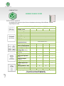
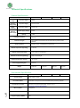
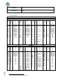
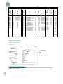
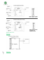
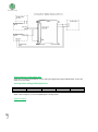
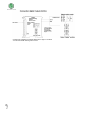
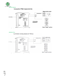
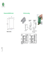
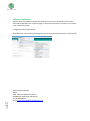
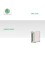
USER GUIDE
ARDBOX FAMILY
Ardbox User Guide:
Contents
ARDBOX FAMILY GUIDE ...................................................................................................... 3
Technical Specifications ...................................................................................................... 4
General Specifications: .............................................................................................................. 4
Performance Specification: ....................................................................................................... 4
I/Os PINOUT ........................................................................................................................ 5
Type Connection: ................................................................................................................ 6
Input connections: .................................................................................................................... 6
Digital In: ............................................................................................................................... 6
Digital/Analog configurable In: ............................................................................................. 6
Output connection: ................................................................................................................... 7
Relay Out: .............................................................................................................................. 7
Digital Out: ............................................................................................................................ 7
Digital/Analog configurable Out: .......................................................................................... 8
Digital Output: ....................................................................................................................... 8
PWM Output: ...................................................................................................................... 10
Analog Out:.......................................................................................................................... 10
Dimension ARDBOX Family: .............................................................................................. 11
DIN rail mounting: ............................................................................................................. 11
Page
2
Software Interface:............................................................................................................ 12
COMPACT PLC.
ARDBOX FAMILY GUIDE
A compact PLC based in Open Source Hardware technology. With different
Input/Outputs Units.
COMPACT PLC ARDUINO 24Vcc ARDBOX
MODEL TYPE
Input Voltage
I max.
Size
Clock Speed
Flash Memory
SRAM
EEPROM
Comunicaciones
TOTAL Input points
PNP
TCH
RELAY
ANALOG
24Vcc
0,5A
100x45x115
16MHz
32KB of wich 0,5KB used by bootlader
2KB
1KB
I2C hasta 127 elementos. –
Puerto Serie RS-232 (1)
6
10
8 (+2)
10
14
10
8 (+2)
10
-
-
2
-
-
-
6
9
* Digital Input (24Vcc)
6
10
-
10
* Interrupt Input HS
-
2
2 (5Vcc)
1
-
-
-
7
14
8
-
10
-
-
-
6
-
2
8
-
TOTAL Output points
Type of signals
Input/Output
configurable (5Vcc)
* Analog Input 10bit
(0-10Vcc)
I/O’s configurable
(24Vcc)
* Analog Output
(0-10Vcc)
* Digital Output (24Vcc)
* PWM Output 8bit
(24Vcc)
* Relay (220Vac - 5A)
Expandability
Reference
I2C - 127 elements
IS.AB20PNP.base
IS.AB20TCH.base
-
Serial Port RS-232
IS.AB18REL.base
IS.AB20AN.base
Page
3
* By using this type of signal can no longer use Digital signal (24Vcc)
You must to read product Datasheet.
(1) With previous request. IMPORTANT
Technical Specifications
General Specifications:
Item
PNP
Power supply
voltage
DC power supply
24Vdc
Operating
voltage range
DC power supply
20.4 to 25.4Vdc
Power
consumption
DC power supply
30VAC max.
External
power supply
Power supply voltage
24Vdc
Power supply output
capacity
700Ma
TCH
RELAY
ANALOG
20MΩ min.at 500Vdc between the AC terminals and the protective earth
terminal.
Insulation resistance
Dialectric strength
2.300 VAC at 50/60 HZ for one minute with a leakage current of 10mA
max. Between all the external AC terminals and the protective earth
terminal.
Shock resistance
80m/s2 in the X, Y and Z direction 2 times each.
Ambient temperature (operating)
0º to 45ºC
Ambient humidity (operating)
10% to 90% (no condensation)
Ambient environment (operating)
With no corrosive gas
Ambient temperature (storage)
-20º to 60ºC
Power supply holding time
2ms min.
Weight
190g max.
190g max..
190g max..
TCH
RELAY
190g max.
Performance Specification:
Item
Control method
I/O control method
Programming language
PNP
Stored program method
Combination of the cyclic scan and immediate refresh processing methods.
Arduino IDE. Based on wiring (Wiring is an Open Source electronics platform
composed of a programming language. “similar to the C”.
http://arduino.cc/en/Tutorial/HomePage
ATmega32u4
Flash Memory
32kb of wich 4 kb used by bootloader
Page
4
Microcontroller
Program capacity (SRAM)
ANALOG
2.5kb
EEPROM
1kb
Clock Speed
16MHz
I/Os PINOUT
PINOUT
ARDBOX PNP
ARDBOX ANALOG
ARDBOX RELAY
ARDBOX TCH
6
Q0.3
9
Q0.2
10
Q0.1
11
Q0.0
13
NC
Gnd
24Vdc
-
Relay 1 Out
LP02
LP03
5
Relay 2 Out
LP04
LP05
6
Relay3 Out
LP06
LP07
7
Relay4 Out
LP08
LP09
8
Relay5 Out
LP10
LP11
9
Relay6 Out
LP12
LP13
10
Rela7 Out
LP14
12
Digital In/Out
5Vdc*1
Function
Q0.4
4
Arduino
Pin
5
LP00
LP01
Ardbox
Connect
or
Q0.5
Analog/PWM/
digital Output
Analog/PWM/
digital Output
Analog/PWM/
digital Output
Analog/PWM/
digital Output
Analog/PWM/
digital Output
Analog/PWM/
digital Output
Analog/PWM/
digital Output
NC
GND
24Vdc
Function
3
Arduino
Pin
Q0.6
Ardbox
Connect
or
Digital Input
Digital Input
Digital Input
Digital Input
Digital Input
Digital Input
Digital Input
Digital Input
Digital Input
Digital Input
Digital Input
Digital Input
Digital Input
Digital Input
Gnd
Gnd
Power 24Vdc
Function
Function
0
1
2
3
4
5
6
7
8
9
10
11
12
13
Gnd
Gnd
-
Arduino
Pin
Arduino
Pin
LP00
LP01
LP02
LP03
LP04
LP05
LP06
LP07
LP08
LP09
LP10
LP11
LP12
LP13
LP14
Gnd
24Vdc
Ardbox
Connect
or
Ardbox
Connect
or
Left side
LP00
LP01
LP02
LP03
LP04
LP05
LP06
LP07
LP08
LP09
LP10
LP11
LP12
LP13
LP14
Gnd
24Vdc
0
1
2
3
4
5
6
7
8
9
10
11
Gnd
Gnd
Gnd
Gnd
-
Digital Input
Digital Input
Digital Input
Digital Input
Digital Input
Digital Input
Digital Input
Digital Input
Digital Input
Digital Input
Digital Output
Digital Output
Gnd
Gnd
Gnd
Gnd
Power 24Vdc
Gnd
24Vdc
ARDBOX PNP
ARDBOX ANALOG
ARDBOX RELAY
ARDBOX TCH
Ardbox
Connect
or
Arduino
Pin
Function
Ardbox
Connect
or
Arduino
Pin
Function
Ardbox
Connect
or
Arduino
Pin
Function
Ardbox
Connect
or
Arduino
Pin
Function
Right side
RP00
RP01
RP02
RP03
RP04
RP05
RP06
RP07
RP08
RP09
RP10
RP11
RP12
RP13
RP14
RP15
RP16
NC
A0
A1
A2
A3
A4
A5
Gnd
Gnd
Gnd
Gnd
Gnd
Gnd
Gnd
Gnd
Gnd
NC
NC
Digital Input
Digital Input
Digital Input
Digital Input
Digital Input
Digital Input
Gnd
Gnd
Gnd
Gnd
Gnd
Gnd
Gnd
Gnd
Gnd
NC
Gnd
I0.9
Gnd
A0
GND
Analog/ Digital
Input
Analog/ Digital
Input
Analog/ Digital
Input
Analog/ Digital
Input
Analog/ Digital
Input
Analog/ Digital
Input
Analog/ Digital
Input
Analog/ Digital
Input
Analog/ Digital
Input
Com RP10
Digital Input
Digital Output
Digital Output
Digital Output
RPA
RP00
11
Relay 8 Output
RP00
RP01
RP02
RP03
RP04
RP05
RP06
RP07
RP08
RP09
RP10
RP11
RP12
NC
A0
A1
A2
A3
A4
A5
Gnd
Gnd
Gnd
Gnd
Gnd
Gnd
NC
Digital Input
Digital Input
Digital Input
Digital Input
Digital Input
Digital Input
Gnd
Gnd
Gnd
Gnd
Gnd
Gnd
I0.8
A1
I0.7
A2
I0.6
A3
I0.5
A4
I0.4
A5
I0.3
4
I0.2
8
I0.1
12
COM-I0.0
2
0
1
7
Page
5
I0.0
Q0.9
Q0.8
Q0.7
1
Connect to Pin of Arduino Leonardo board.
RP01
13
Digital Input /
Output 5Vdc1
RP02
RP03
RP04
RP05
RP06
Gnd
Gnd
3
2
A0
RP07
A1
RP08
A2
RP09
A3
RP10
A4
RP11
A5
Digital Input
Digital Input
Analog/ Digital
Input
Analog/ Digital
Input
Analog/ Digital
Input
Analog/ Digital
Input
Analog/ Digital
Input
Analog/ Digital
Input
RP13
RP14
12
Relay 1
Output
RP15
RP16
13
Relay 2
Output
LEDS
0
1
2
3
4
5
6
7
8
9
10
11
12
13
14
15
16
17
18
19
NC
NC
RP04
RP05
LP02
LP00
LP06
LP04
LP10
LP08
RPA
LP12
NC
NC
RP07
RP06
RP09
RP08
RP11
RP10
Digital Input
Digital Input
Relay Output
Relay Output
Relay Output
Relay Output
Relay Output
Relay Output
Relay Output
Dig. In/Out.
An/Dig Input
An/Dig Input
An/Dig Input
An/Dig Input
An/Dig Input
An/Dig Input
RP00
RP01
RP02
RP03
RP04
RP05
RP06
RP07
RP08
RP09
RP10
RP11
RP12
NC
A0
A1
A2
A3
A4
A5
Gnd
Gnd
Gnd
Gnd
Gnd
Gnd
RP13
RP14
12
RP15
RP16
13
Function
Analog/PWM/Dig. Out
Analog/PWM/Dig. Out
Analog/PWM/Dig. Out
Analog/PWM/Dig. Out
Analog/PWM/Dig. Out
Analog/PWM/Dig. Out
Digital Output
Analog/PWM/Dig. Out
Digital Output
Digital Output
Analog/ Digital Input
Digital Input
Analog/ Digital Input
Analog/ Digital Input
Analog/ Digital Input
Analog/ Digital Input
Analog/ Digital Input
Analog/ Digital Input
Analog/ Digital Input
Analog/ Digital Input
Arduino Pin
Q0.1
Q0.0
Q0.3
Q0.2
Q0.5
Q0.4
Q0.7
Q0.6
Q0.9
Q0.8
I0.1
I0.0
I0.3
I0.2
I0.5
I0.4
I0.7
I0.6
I0.9
I0.8
Ardbox
Connector
0
1
2
3
4
5
6
7
8
9
10
11
12
13
14
15
16
17
18
19
ARDBOX TCH
Function
SIGNAL
NC
Digital Input
Digital Input
Digital Input
Digital Input
Digital Input
Digital Input
Gnd
Gnd
Gnd
Gnd
Gnd
Gnd
Gnd
Gnd
Gnd
NC
SIGNAL
BOX
NC
A0
A1
A2
A3
A4
A5
Gnd
Gnd
Gnd
Gnd
Gnd
Gnd
Gnd
Gnd
Gnd
NC
BOX
Function
RP00
RP01
RP02
RP03
RP04
RP05
RP06
RP07
RP08
RP09
RP10
RP11
RP12
RP13
RP14
RP15
RP16
ARDBOX RELAY
Function
Arduino Pin
ARDBOX ANALOG
Ardbox
Connector
ARDBOX PNP
NC
Digital
Input
Digital
Input
Digital
Input
Digital
Input
Digital
Input
Digital
Input
Gnd
Gnd
Gnd
Gnd
Gnd
Gnd
Relay 1
Output
Relay 2
Output
Type Connection:
Input connections:
Digital In:
Digital/Analog configurable In:
Page
6
Some pins can work in three different modes. Analog and Digital input signal. IMPORTANT: to have the
switch in correct position.
Output connection:
Page
7
Relay Out:
Digital Out:
Digital/Analog configurable Out:
Some pins can work in three different modes. Analog and Digital output signal. IMPORTANT: to have the
switch in correct position.
Switch position Analog/PWM/digital Out:
A
On
On
B
On
Off
C
On
On
D
On
On
* Whith 10Vdc configure, you can use Digital signal or Analog Signal:
Page
8
Digital Output:
Vout
10Vdc
24Vdc
Page
9
Configure by software for work like digital form: High or Low level.
You can use PWM: 255=High and 0=Low
PWM Output:
Configure by software for work using PWM in range value: 0- 255.
Analog Out:
Page
10
Configure by software for work using PWM in range value: 0- 255.
Dimension ARDBOX Family:
Page
11
45mm de ancho
DIN rail mounting:
Software Interface:
Arduino IDE is compatible for programm these PLCs. You must to download a start code in
www.industrialshields.com at product page in “document files”section and then It’s necessary
open it with Arduino IDE.
Configuration about Arduino IDE:
All Ardbox PLCs use an Arduino Leonardo and you need to choose these opcion in Arduino IDE.
Page
12
About Industrial Shields:
SPAIN
Avda. Castell de Barberà 26, nave 9
08210 Barberà del Vallès (Barcelona)
Tel.+34 635693611
Mail: [email protected]