1
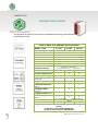
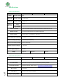
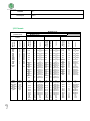
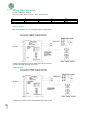
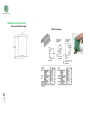
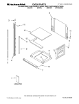
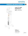
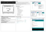
USER GUIDE
M-DUINO FAMILY
M-Duino User Guide:
Contents
M-DUINO FAMILY GUIDE .................................................................................................... 3
Specifications ...................................................................................................................... 4
I/O Pinout: ........................................................................................................................... 5
HOW TO CONNECT:............................................................................................................. 6
Analog/ Digital In:.......................................................................................................................... 6
Digital Input: .................................................................................................................................. 7
Analog/PWM/digital Out: ............................................................................................................. 8
Digital Output: ....................................................................................................................... 8
PWM Output: ........................................................................................................................ 8
Analog Out:............................................................................................................................ 9
Page
2
Software Interface:............................................................................................................ 11
COMPACT PLC.
M-DUINO FAMILY GUIDE
A compact PLC based in Open Source Hardware technology. With different
Input/Outputs Units.
CONECTABLE PLC ARDUINO 24Vcc M-DUINO
MODEL TYPE
Input Voltage
I max.
Size
Clock Speed
Flash Memory
SRAM
EEPROM
Comunicaciones
TOTAL Input points
21 I/Os
42 I/Os
58 I/Os
24Vcc
0,5A
100x45x115
16MHz
32KB of wich 0,5KB used by bootlader
2KB
1KB
I2C hasta 127 elementos. –
Puerto Serie RS-232 (1) – Ethernet Port
13
26
36
8
16
22
6
12
16
* Digital Input (24Vcc)
13
26
36
* Interrupt Input HS
2
4
6
3
6
8
* Digital Output (24Vcc)
8
16
22
* PWM Output 8bit
3
6
8
TOTAL Output points
Type of signals
* Analog Input 10bit
(0-10Vcc)
(24Vcc)
* Analog Output
(0-10Vcc)
(24Vcc)
Expandability
Reference
I2C - 127 elements
IS.MDUINO.base.21
- Serial Port RS-232 Ethernet
IS.MDUINO.base.42
IS.MDUINO.base.58
Page
3
* By using this type of signal can no longer use Digital signal
(24Vcc)
You must to read product Datasheet.
(1) With previous request. IMPORTANT
Ref. MDUINO-GUIDE.2014.3
Specifications
General Specifications:
Item
M-DUINO 21 IOs
Power supply
voltage
DC power supply
Operating
voltage range
DC power supply
20.4 to 25.4Vdc
Power
consumption
DC power supply
30VAC max.
External
power supply
M-DUINO 58 IOs
24Vdc
Power supply
voltage
24Vdc
Power supply
output capacity
700Ma
Insulation resistance
M-DUINO 42 IOs
20MΩ min.at 500Vdc between the AC terminals and the protective earth terminal.
Dialectric strength
2.300 VAC at 50/60 HZ for one minute with a leakage current of 10mA max. Between all
the external AC terminals and the protective earth terminal.
Shock resistance
80m/s2 in the X, Y and Z direction 2 times each.
Ambient temperature (operating)
Ambient humidity (operating)
Ambient environment (operating)
Ambient temperature (storage)
0º to 45ºC
10% to 90% (no condensation)
With no corrosive gas
-20º to 60ºC
Power supply holding time
2ms min.
Weight
250g max.
385g max.
520g max.
Performance Specification:
Item
Control method
I/O control method
Programming language
M-DUINO 21 IOs
Combination of the cyclic scan and immediate refresh processing methods.
Arduino IDE. Based on wiring (Wiring is an Open Source electronics platform composed of a
programming language. “similar to the C”. http://arduino.cc/en/Tutorial/HomePage
Microcontroller
ATmega2560
Flash Memory
256kb of wich 8 kb used by bootloader
Program capacity (SRAM)
M-DUINO 58 IOs
Stored program method
4
Page
M-DUINO 42 IOs
8kb
EEPROM
4kb
Clock Speed
16MHz
I/O Pinout:
M-DUINO 58 IOs
M-DUINO 42 IOs
Base
(common unit)
M-DUINO 21 IOs
B Zone
C Zone
D Zone
Page
5
SCL
SDA
RX1
TX1
RX2
TX2
RX3
TX3
PIN9
PIN7
PIN3
PIN2
TX0
RX0
21
20
19
18
17
16
15
14
9
7
3
2
1
0
SCL
SDA
RX1
TX1
RX2
TX2
RX0
TX0
bus
bus
bus
bus
TX0
RX0
24Vdc
Gnd
-
Gnd
AREF
IOREF
IOREF1
7Vdc (out)
Gnd
3.3Vdc (out)
Gnd
5Vdc (out)
gnd
AREF
IOREF
IOREF1
+7Vdc
Gnd
+3.3Vdc
Gnd
5Vdc
gnd
I0.12
A5
I0.11
A4
I0.10
A3
I0.9
A2
I0.8
A1
I0.7
A0
COM-I0.6
I0.6
COM-I0.5
I0.5
COM-I0.4
I0.4
COM-I0.3
I0.3
COM-I0.2
I0.2
COM-I0.1
I0.1
COM-I0.0
I0.0
NC
3
NC
2
NC
26
NC
25
NC
24
NC
23
NC
22
NC
NC
Q0.7
NC
NC
6
Q0.6
5
Q0.5
4
Q0.4
Q0.3
Q0.2
Q0.1
Q0.0
NC
NC
Gnd
Gnd
40
39
38
37
36
NC
NC
Gnd
Gnd
Analog/ Digital
In
Analog/ Digital
In
Analog/ Digital
In
Analog/ Digital
In
Analog/ Digital
In
Analog/ Digital
In
GND I0.6
Interrupt 1 In
GND I0.5
Interrupt 0 In
GND I0.4
Digital Input
GND I0.3
Digital Input
GND I0.2
Digital Input
GND I0.1
Digital Input
GND I0.0
Digital Input
NC
NC
Analog/PWM
/digital Out
Analog/PWM
/digital Out
Analog/PWM
/digital Out
Digital Out
Digital Out
Digital Out
Digital Out
Digital Out
NC
NC
Gnd
Gnd
I1.12
I1.11
I1.10
I1.9
I1.8
I1.7
COM-I1.6
I1.6
COM-I1.5
I1.5
COM-I1.4
I1.4
COM-I1.3
I1.3
COM-I1.2
I1.2
COM-I1.1
I1.1
COM-I1.0
I1.0
A11 Analog/ Digital
In
A10 Analog/ Digital
In
A9 Analog/ Digital
In
A8 Analog/ Digital
In
A7 Analog/ Digital
In
A6 Analog/ Digital
In
NC
GND I1.6
19
Interrupt 4 In
NC
GND I1.5
18
Interrupt 5 In
NC
GND 1.4
31
Digital Input
NC
GND I1.3
30
Digital Input
NC
GND I1.2
29
Digital Input
NC
GND I1.1
28
Digital Input
NC
GND I1.0
27
Digital Input
NC
NC
Q1.7
NC
NC
11
Q1.6
10
Q1.5
8
Q1.4
Q1.3
Q1.2
Q1.1
Q1.0
NC
NC
Gnd
Gnd
45
44
43
42
41
NC
NC
Gnd
Gnd
NC
NC
Analog/PWM/
digital Out
Analog/PWM/
digital Out
Analog/PWM/
digital Out
Digital Out
Digital Out
Digital Out
Digital Out
Digital Out
NC
NC
Gnd
Gnd
I2.12
I2.11
I2.10
NC
NC
A15
I2.9
A14
I2.8
A13
I2.7
A12
COM-I2.6
I2.6
COM-I2.5
I2.5
COM-I2.4
I2.4
COM-I2.3
I2.3
COM-I2.2
I2.2
COM-I2.1
I2.1
COM-I2.0
I2.0
NC
21
NC
20
NC
NC
NC
35
NC
34
NC
33
NC
32
NC
NC
Q2.7
Q2.6
NC
NC
NC
13
Q2.5
12
Q2.4
Q2.3
Q2.2
Q2.1
Q2.0
NC
NC
Gnd
Gnd
NC
49
48
47
46
NC
NC
Gnd
Gnd
Function
Arduino Pin
M-Duino
Connector
Function
Arduino Pin
M-Duino
Connector
Function
Arduino Pin
M-Duino
Connector
Function
Arduino Pin
M-Duino
Connector
A Zone
NC
NC
Analog/ Digital
In
Analog/ Digital
In
Analog/ Digital
In
Analog/ Digital
In
GND I2.6
Interrupt 2 In
GND I2.5
Interrupt 3 In
NC
NC
GND I2.3
Digital Input
GND I2.2
Digital Input
GND I2.1
Digital Input
GND I2.0
Digital Input
NC
NC
NC
Analog/PWM/
digital Out
Analog/PWM/
digital Out
NC
Digital Out
Digital Out
Digital Out
Digital Out
NC
NC
Gnd
Gnd
HOW TO CONNECT:
Analog/ Digital In:
Pins I0.7, I0.8, I0.9, I0.10, I0.11, I0.12, I1.7, I1.8, I1.9, I1.10, I1.11, I1.12, I2.7, I2.8, I2.9 and I2.10, can
work in two different modes. Analog and Digital input signal.
Page
6
Select the correct “SWITCH” in”Analog” position. WARNING:DO NOT
CONNECT 24Vdc – (10Vdc max.)
Select the correct “SWITCH” in ”Digital” position.
Digital Input:
Page
7
Pins: I0.0, I0.1, I0.2, I0.3, I0.4, I1.0, I1.1, I1.2, I1.3, I1.4, I2.0, I2.1, I2.2, I2.3.
Analog/PWM/digital Out:
You can configure the signal of:
Q0.5, Q0.6, Q0.7, Q1.5, Q1.6, Q1.7, Q2.5, Q2.6 and Q2.7.
A
On
On
B
On
Off
C
On
On
D
On
On
Digital Output:
With 10Vdc configure, you can use Digital signal or Analog Signal:
Configure by software for work as digital form: High or Low level.
You can use PWM: 254=High and 0=Low
PWM Output:
Page
8
Configure by software for work using PWM in range value: 0- 254.
Vout
10Vdc
24Vdc
Analog Out:
Page
9
Configure by software for work using PWM in range value: 0- 255.
Mechanical Characteristics
-
Dimension M-duino Family:
Page
10
-
DIN rail mounting:
Software Interface:
Arduino IDE is compatible for programm these PLCs. You must to download a start code in
www.industrialshields.com at product page in “document files”section and then It’s necessary
open it with Arduino IDE.
Configuration about Arduino IDE:
All Ardbox PLCs use an Arduino Leonardo and you need to choose these opcion in Arduino IDE.
Page
11
About Industrial Shields:
SPAIN
Avda. Castell de Barberà 26, nave 9
08210 Barberà del Vallès (Barcelona)
Tel.+34 635693611
Mail: [email protected]
FAQ:
I can not find a specification for the inputs. What are the switching
levels (VIH, VIL) and how much current is required to drive the inputs?
What are the minimum and maximum voltage levels that can be applied
without damage?
How do the outputs work? Are these Open-Collector (or Open-Drain)
outputs or Push-Pull type? Is it possible to connect inductive loads (is
the output equipped with a recovery diode)? The maximum allowed current
for each output channel is given as 80mA - is it valid for both
directions, i.e. connecting loads to 24V and GND?
Do the digital signals that work at TTL level (e.g. I2C) have protection
elements in order to use the Ardbox in a harsh industrial environment? NOT YET
What does 24Vdc stand for? I only know 24VDC as an abbreviation for 24
volts "direct current" - is it the same? Yes. It is 24 VDC
What class of isolation do the relays outputs provide?
What type of fuses are installed in the device?
Page
12
As this is a complete device (not just a board level component like the
Arduino itself) do you have (or plan to have) some certificate of CE
compliance?