1
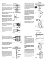
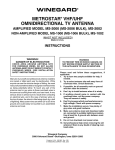
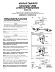
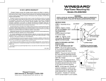
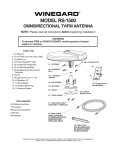
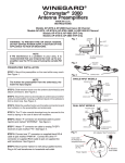
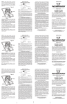
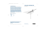
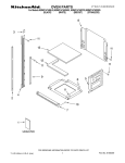
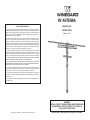
RV ANTENNA
90 DAY LIMITED WARRANTY
Model RV-7020
Winegard Company warrants this Winegard product against any defects in materials or
workmanship within 90 (ninety) days from date of purchase. No warranty claim will be honored
unless at the time the claim is made, you present proof of purchase to an authorized Winegard
dealer (if unknown, please contact Winegard Company, 3000 Kirkwood Street, Burlington, IA
52601-2000, Telephone 319-754-0600).
INSTRUCTIONS
Made in U.S.A.
Winegard Company (at its option) will either repair or replace the defective product at no
charge to you. This warranty covers parts, but does not cover any costs incurred in removal,
shipping or reinstallation of the product. This limited warranty does not apply if the product is
damaged, deteriorates, malfunctions or fails from: misuse, improper installation, abuse, neglect,
accident, tampering, modification of the product as originally manufactured by Winegard, usage
not in accordance with product instructions or acts of nature such as damage caused by wind,
lightning, ice or corrosive environments such as salt spray and acid rain.
The 90 Day Warranty is provided on the condition that the equipment is properly delivered
with all handling and freight charges prepaid to your Winegard dealer for return to our factory
for repair or replacement. Winegard dealers will arrange for the replacement or repair and
return to you without charge the product which failed due to defective material or workmanship.
WINEGARD COMPANY WILL NOT ASSUME ANY LIABILITIES FOR ANY OTHER WARRANTIES, EXPRESS OR IMPLIED, MADE BY ANY OTHER PERSON.
ALL OTHER WARRANTIES WHETHER EXPRESS, IMPLIED OR STATUTORY INCLUDING WARRANTIES OF FITNESS FOR A PARTICULAR PURPOSE AND MERCHANTABILITY
ARE LIMITED TO THE 90-DAY PERIOD OF THIS WARRANTY.
The foregoing shall be the sole and exclusive remedy of any person, whether in contract, tort
or otherwise, and Winegard shall not be liable for incidental or consequential damage or
commercial loss, or from any other loss or damage except as set forth above.
Some states do not allow limitations on how long an implied warranty lasts, or the exclusion
of limitation of incidental or consequential damages, so the above limitations or exclusions may
not apply to you.
This warranty gives you specific legal rights and you may also have other rights which vary
from state to state.
WARNING
INSTALLATION OF THESE ANTENNAS NEAR POWER LINES
IS DANGEROUS. FOR YOUR SAFETY, FOLLOW THE INSTALLATION INSTRUCTIONS.
Printed in U.S.A. 1450942
© Winegard Company 1997 Rev. 8/97
Winegard Company • 3000 Kirkwood Street • Burlington, IA 52601-2000
INSTALLATION
STEP 1. Remove antenna from carton and
unfold elements until they lock into place.
BOOM PLUG
STEP 12. Mount mast bracket 22" below
roof line. Use two (2) #10 x 1" sheet metal
screws provided in hardware bag. See Figure 5. Mount bottom bracket 18" below top
mast bracket, making sure brackets line up
vertically. See Figure 5.
STEP 2. Connect loose elements to stud
rivets. Use flat washers and wing nuts from
hardware bag to secure loose elements. See
Figure 1.
STEP 3. Insert boom plugs into top and
bottom of mast. See Figure 1.
WING NUT &
FLAT WASHER
Figure 1
STEP 4. Insert retaining clip into hole just
below downlead connection. See Figure 2.
STEP 5. Slide weather boot from matching
transformer onto coax. To install the F-connectors, strip the ends of the RG-59 cable as
shown in Figure 3A.
RETAINING
CLIP
STEP 14. Place storage brackets approximately 12" from end of long VHF element
and attach to vehicle with one (1) #10 x 1"
sheet metal screw. See Figure 7.
Figure 2
STORAGE
BRACKETS
BOTH SIDES
STEP 14
22"
MAST
#10 x 1" BRACKETS
SCREWS
Figure 5
LOCKING
BOLT THRU
TOP HOLE
LOWER MAST
BRACKET
STEP 15. Run downlead to TV set, leave
enough slack so antenna may be raised.
STEP 6. Push back and twist the braid around
the Dielectric until it butts against the cable
jacket. See Figure 3B.
RG/59
1/4"
Figure 3A
STEP 7. Screw the F-connector onto the
cable jacket until the Dielectric butts against
the inner retaining ring. Cut the center conductor off flush with the end of the connector.
See Figure 3C.
STEP 13. Slide antenna assembly down
thru mast brackets. Insert locking bolt thru
top hole in mast so it will be above lower
mast bracket. See Figure 6. Antenna should
rest on locking bolt.
ROOF LINE
1/2"
Figure 6
3/4"
Jacket
#10 x 1"
SCREWS
Twist Braid over Jacket
RG/59
STORAGE BRACKET
Dialectric
Center
Conductor
VHF ELEMENT
Figure 3B
Type F-Connector
STEP 8. Attach matching transformer to
downlead stud rivets with washers and wing
nuts supplied from hardware bag. See Figure
4.
STEP 9. Screw coax downlead onto matching transformer, making sure to slide weather
boot over connection. See Figure 4.
RG/59
Figure 3C
Center Conductor to
be Flush With End of
Connector.
#10 x 1" SCREW
12"
Figure 7
LOWER BRACKET
NOTE: Antenna may be rotated when in
the operating position to obtain best
picture.
STEP 10. Secure matching transformer to
retaining clip. See Figure 4.
STEP 11. Select location on vehicle for antenna where downlead entry will be made and
where antenna may be lowered without protruding above roof line. Hold antenna in position and mark location of mast to aid in mounting mast brackets.
To Raise Antenna to Operating
Position:
Remove locking bolt and wing nut from hole
in center of mast, slide antenna up thru
brackets until hole at bottom of mast is just
above bottom mast bracket and insert locking bolt and secure with wing nut. See
Figure 5.
WING NUT
& WASHER
CLIP
MATCHING
TRANSFORMER
Figure 4
WEATHER
BOOT
To Lower Antenna to Travel Position:
Rotate antenna until elements are on side
facing vehicle. Remove locking bolt and
wing nut, slide antenna down thru mast
brackets until VHF element rests on storage brackets. Replace locking bolt in top
hole below bottom mast bracket and secure
bolt and wing nut. See Figure 9.
Figure 8
LOCKING
BOLT &
WING NUT
Figure 9
LOCKING BOLT
THROUGH
LOWER HOLE