1
GIGAHERTZ
SOLUTIONS
R
GIGAHERTZ GIGAHERTZ GIGAHERTZ GIGAHERTZ GIGAHE
SOLUTIONS SOLUTIONS SOLUTIONS SOLUTIONS SOLUTIO
GIGAHERTZ GIGAHERTZ GIGAHERTZ GIGAHERTZ GIGAH
SOLUTIONS SOLUTIONS SOLUTIONS SOLUTIONS SOLUT
TZ GIGAHERTZ GIGAHERTZ GIGAHERTZ GIGAHERTZ GIGA
NS SOLUTIONS SOLUTIONS SOLUTIONS SOLUTIONS SOLU
RTZ GIGAHERTZ GIGAHERTZ GIGAHERTZ GIGAHERTZ GIG
WithSOLUTIONS
F1B2H31 (Frequency
Filter Module: 16 Hz Band Pass/50Hz High Pass/2kHz High Pass)
ONS
SOLUTIONS
SOLUTIONS SOLUTIONS SOL
ERTZ GIGAHERTZ GIGAHERTZ GIGAHERTZ GIGAHERTZ G
TIONS SOLUTIONS SOLUTIONS SOLUTIONS SOLUTIONS SO
HERTZ GIGAHERTZ GIGAHERTZ GIGAHERTZ GIGAHERTZ G
UTIONS SOLUTIONS SOLUTIONS SOLUTIONS SOLUTIONS S
AHERTZ GIGAHERTZ GIGAHERTZ GIGAHERTZ GIGAHERTZ
LUTIONS SOLUTIONS SOLUTIONS SOLUTIONS SOLUTIONS
IGAHERTZ GIGAHERTZ GIGAHERTZ GIGAHERTZ GIGAHER
OLUTIONS SOLUTIONS SOLUTIONS SOLUTIONS SOLUTION
GIGAHERTZ GIGAHERTZ GIGAHERTZ GIGAHERTZ GIGAHE
SOLUTIONS SOLUTIONS SOLUTIONS SOLUTIONS SOLUTIO
GIGAHERTZ GIGAHERTZ GIGAHERTZ GIGAHERTZ GIGAH
SOLUTIONS SOLUTIONS SOLUTIONS SOLUTIONS SOLUT
GIGAHERTZ GIGAHERTZ GIGAHERTZ GIGAHERTZ GIGA
SOLUTIONS SOLUTIONS SOLUTIONS SOLUTIONS SOLU
GIGAHERTZ GIGAHERTZ GIGAHERTZ GIGAHERTZ GIG
SOLUTIONS SOLUTIONS SOLUTIONS SOLUTIONS SOL
GIGAHERTZ GIGAHERTZ GIGAHERTZ GIGAHERTZ G
SOLUTIONS SOLUTIONS SOLUTIONS SOLUTIONS SO
GIGAHERTZ GIGAHERTZ GIGAHERTZ GIGAHERTZ G
SOLUTIONS SOLUTIONS SOLUTIONS SOLUTIONS S
GIGAHERTZ GIGAHERTZ GIGAHERTZ GIGAHERTZ
SOLUTIONS SOLUTIONS SOLUTIONS SOLUTIONS
GIGAHERTZ GIGAHERTZ GIGAHERTZ GIGAHER
SOLUTIONS SOLUTIONS SOLUTIONS SOLUTION
- Functions
& Controls
GIGAHERTZ
GIGAHERTZ GIGAHERTZ GIGAHE
SOLUTIONS
SOLUTIONS
SOLUTIONS SOLUTIO
- Operation
and
Maintenance
GIGAHERTZ GIGAHERTZ GIGAHERTZ GIGAH
- Measurement
Instructions
SOLUTIONS SOLUTIONS
SOLUTIONS SOLUT
GIGAHERTZ GIGAHERTZ GIGAHERTZ GIGA
- Field Theory
SOLUTIONS SOLUTIONS SOLUTIONS SOLU
GIGAHERTZ GIGAHERTZ GIGAHERTZ GIG
SOLUTIONS
SOL
It is important to read carefully theSOLUTIONS
instruction manual prior SOLUTIONS
to using the field meter. Important
information regarding
safety, use and maintenance is provided herein.
GIGAHERTZ GIGAHERTZ GIGAHERTZ G
SOLUTIONS SOLUTIONS SOLUTIONS SO
1
ME 3951A
User's Guide
GIGAHERTZ
SOLUTIONS
R
Preface
With the field meters of the ME 3 series, GIGAHERTZ SOLUTIONS® sets new standards in electromagnetic field testing. Professional measurement engineering is offered with a unique
price/performance ratio - the only one of its kind worldwide. This was made possible through the
consistent use of innovative integrated components, some of which have patents pending, as well
as highly sophisticated production engineering.
The field meter you purchased allows a competent assessment of AC electric as well as AC
magnetic field exposures according to the internationally recognized Swedish guidelines for computer monitors (TCO/MPR), covering the entire frequency range from 5 Hz up to 400 kHz.
We appreciate the confidence you showed when purchasing the ME 3951A field meter. With the
confidence that your expectations will be met, we wish you great success in collecting useful
information with this field meter.
© by the manufacturer: GIGAHERTZ SOLUTIONS® GmbH, D-90579 Langenzenn. All rights reserved. No part of this
document may be reproduced or transmitted in any form or by any means, electronic or mechanical, including photocopying, or recorded by any information storage or retrieval system, without permission in writing by GIGAHERTZ
SOLUTIONS® GmbH.
2
© by GIGAHERTZ SOLUTIONS® GmbH, 90579 Langenzenn, www.gigahertz-solutions.com
Contents, Safety Instructions
GIGAHERTZ
SOLUTIONS
Contents
Page
Safety instructions ........................................................................................................................3
Function & controls ........................................................................................................................4
Getting started ...............................................................................................................................6
Measurement instructions ...............................................................................................................8
Changing Batteries .......................................................................................................................16
Battery management ....................................................................................................................18
Safety Instructions:
It is important to read carefully the instruction manual prior to using the field meter. Important information regarding safety, use and maintenance is provided herein.
The adapter is only to be used with the specified, rechargeable battery. Never try to recharge nonchargeable primary batteries (e.g. zinc-coal or alkaline batteries) with it: Explosion Hazard!
The grounding of the field meter required for the electric field measurements should be performed
with the supplied grounding lead, which can be connected to bare water, gas or heating pipes. If
there is none of the above-mentioned grounding options available, a licensed electrician could
temporarily also make use of the grounding conductor in a grounded outlet. In this case, however, an electric shock hazard may occur when the grounding clip touches the current-carrying
phase conductor.
To prevent shock hazards or the destruction of the field meter, neither the instrument itself nor the
adapter should ever come into contact with water. The penetration of water into the case may lead
to the destruction of the electronics inside. Field meters are not to be stored outdoors or used
during rain. Clean the case only from the outside, using a slightly moist cloth. Do not use cleaners
or sprays.
Prior to cleaning the field meter or opening the case, shut it off and unplug all extension cords.
There are no user-serviceable parts inside the instrument.
Due to the high sensitivity level, the electronics of the field meter are very sensitive to heat, impact
as well as touch. Therefore do not leave the instrument in the hot sun, on a heating element or the
like. Do not let it drop nor try to manipulate its electronics inside when the case is open.
This field meter should only be used for the purposes described herein and only in combination
with supplied or recommended accessories.
© by GIGAHERTZ SOLUTIONS® GmbH, 90579 Langenzenn, www.gigahertz-solutions.com
3
R
GIGAHERTZ
SOLUTIONS
R
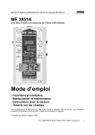
Function & Controls
Battery Charging
Ground
Extension cord of the supplied
adapter: 12-24 VDC, with (+)
at the internal conductor and
(-) at the external conductor.
Only to be used during battery
charging
see pages 6, 18
Connection of the grounding
lead (for electric field testing)
see page 9
Field type
E: Electric Field
M: Magnetic Field
Test: Offset Display
Range Selection
see pages 7, 10, 11
200 nT/Vm: (fine)
0 to 199.9 Nanotesla (nT)
0 to 199.9 Volt per Meter (V/m)
2000 nT/Vm: (coarse)
0 to 1999 Nanotesla (nT)
0 to 1999 Volt per Meter (V/m)
Operation
"Speaker Icon": Speaker turned on
On: Field meter turned on
Off : Field meter turned off
see page 9
see pages 7, 11, 18
DC - Signal output
0 to -1 VDC Signal output
Suitable for long-term monitoring with a data logger or data
plotter, but also for connecting
the optional external display
unit (DP 3000A)
Frequency Filter F1B2H31
16 Hz Band pass, 50 Hz High
pass, 2 kHz Highpass, for building biology assessments to
identify railway systems, electric power grid as well as harmonics of higher frequencies
see page 15
see pages 11, 12, 14
AC - Signal output
1 VAC at maximum display:
Connector for a spectrum
analyzer to analyze the frequency spectrum of the measured signals. At maximum
display, the maximum frequency output is 30 kHz.
Light diode: comes on while
battery is being charged
see page 15
see page 19
see page 18
Button to be pressed for the
display of the battery status as
well as the display check
Display of the Field Type in Use
Dash at the top:
Electric field
strength is displayed
Dash at the bottom: M a g n e t i c
flux density is displayed
Two Dashes: Self-diagnostics
LC-Display: 3.5-digit display of the measurement value (mean value)
see page 19
Picture 01
4
© by GIGAHERTZ SOLUTIONS® GmbH, 90579 Langenzenn, www.gigahertz-solutions.com
GIGAHERTZ
SOLUTIONS
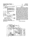
Function & Controls
Sensor for AC Electric
Fields ("Field plate")
Switch to short-circuit the
magnetic sensor, which is only
used by the manufacturer for
calibration purposes.
Sensor for AC Magnetic
Fields
see pages 7
Pegs to hold the rechargeable
battery in place
see pages 7
Switch to short-circuit the field
plate, which is only used by the
manufacturer for calibration
purposes
Rechargeable Battery (”9
Volt E-Block”)
Caution: Battery should only
be used within the supplied
isolation compartment made
of cardboard in order to avoid
short-circuit damage of the
instrument.
see pages 17
Frequency Filter Module
F1B2H31
Can be replaced with modules featuring other threshold
frequencies.
see pages 11, 12, 14
Battery Compartment
LC-Display: 3.5-digit display
of the measurement value
(RMS) including field type and
low batt. indicator
2 Miniature Speakers in a
magnetically shielded circuit
see page 19
Picture 02
© by GIGAHERTZ SOLUTIONS® GmbH, 90579 Langenzenn, www.gigahertz-solutions.com
5
R
GIGAHERTZ
SOLUTIONS
R
Instrument Contents, Getting Started
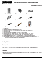
Instrument Contents:
1.)
2.)
3.)
4.)
5.)
6.)
7.)
8.)
9.)
1.)
2.)
3.)
4.)
5.)
6.)
7.)
8.)
9.)
Field meter
Adapter with external voltage jack (2.0 mm)
Grounding lead (5 m) with jack plugs (2.5 mm, mono) and alligator clip
Grounding clip
BNC measurement adapter on jack plug (3.5 mm, mono)
Measurement jack adapter (3.5 mm, mono) on jack plug (2.5 mm, mono)
Jack plug (2.5 mm, mono) for creating your own measurement adapter
Wedge for opening the case to change batteries or frequency filter modules
Rechargeable battery with 9 V nominal voltage (Depending on shipping conditions, it is
sometimes already inserted into the field meter.).
Getting Started
Turning On
If no display is activated, insert rechargeable battery. (See section "Changing Battery").
Charging
If display shows low-batt. indicator, charge battery or insert a fully charged battery. (See section
"Battery Management").
6
© by GIGAHERTZ SOLUTIONS® GmbH, 90579 Langenzenn, www.gigahertz-solutions.com
Function Testing, Offset
GIGAHERTZ
SOLUTIONS
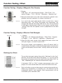
Function Testing - Display of Magnetic Flux Density:
1. Display:
Field Type = “M”, Measurement Range = ”200 nT/Vm”, Frequency Range = ”5 Hz - 400 kHz”, Operation = "Speaker Icon”
2. Move the field meter in fast and short movements around its longitudinal axis back and forth, as shown in picture 03.
Picture 03
As a result, the static geomagnetic field is turned into a "quasi
alternating field." The faster and greater the movements, the
stronger the induced alternating field will be. This will be reflected
in the higher measurement values on the display and the faster
"rattling" noise from the speaker, which is proportional to the field
strength.
Function Testing - Display of Electric Field Strength:
1. Display:
Field Type = “E”, Measurement Range = ”200 nT/Vm”, Frequency Range = ”5 Hz - 400 kHz”, Operation = "Speaker Icon”
Tap here!
2. Keep the field meter steady while tapping the front of the case
with your fingers, as shown in picture 04.
Picture 04
Due to your fingers' mass potential a "quasi AC electric field" is
created whose strengths is reflected through higher measurement
values on the display and the faster "rattling" noise from the speaker.
Defining the Offset:
Turn on the instrument and set the switch "field type" to the "test"
position. On the left-hand side of the display a "1" (as icon for the
test mode) will appear and on the right-hand side either "00.0" or
"000", depending on the selected measurement range.
If instead of "000" or "00.0" a higher measurement value is displayed, this value would reflect the current deviation from zero.
Picture 05
Such a situation can occur because of current environmental conditions (e.g. temperature, air humidity, etc.) The tolerance of the
subsequent electric and magnetic field measurements will be
increased by this deviation value.
© by GIGAHERTZ SOLUTIONS® GmbH, 90579 Langenzenn, www.gigahertz-solutions.com
7
R
GIGAHERTZ
SOLUTIONS
R
Measurement Instructions
Measurement Instructions
Introduction to the Properties of AC Electric and Magnetic Fields
Generally speaking, the sensory organs of the human body cannot perceive alternating electric
and magnetic fields. These fields are "simply there" and expand into three-dimensional space, following rather complex physical laws. For measurement practice, the following properties of alternating electric and magnetic fields are very important:
1. Any measurement is always determined by position as well as direction. The slightest change
in position or direction of the field meter can have substantial consequences for the measurement value, especially in AC magnetic fields.
2. Electric as well as magnetic fields not only penetrate into solid materials including walls, glass
or the like, but also pass right through them. This holds especially true for magnetic fields,
whose shielding is rather costly.
3. AC electric fields occur whenever an alternating voltage is applied. In residential situations, for
example, all plugged-in extension cords and appliances including switches are surrounded by
alternating electric fields. This even holds true when the appliance is turned off! As soon as an
appliance is turned on, there is current flow and an AC magnetic field is added.
4. Beside the field strength, AC electric or magnetic fields are also characterized by their frequency. We distinguish between the low frequencies of the ELF and VLF range between 5 Hz
and 400 kHz as defined by the MPR/TCO guidelines for the assessment of computer monitors
as well as all the higher frequencies including radio waves and microwaves. Furthermore there
are also static magnetic and electrostatic fields, each of which requires a totally different
approach to testing just like RF radiation.
Introduction to Measurement Instructions
In order to obtain meaningful testing results, the Ökotest magazine (6/96) demands the following
minimum requirements for testing equipment of electric and magnetic fields in the ELF and VLF
range:
1. Separate measurements of AC electric fields (with ground reference) and AC magnetic fields.
2. Reproducible, high accuracy.
3. Flat frequency response across the entire specified frequency range, which should at least cover
the railway frequency 16.67 Hz all the way through to the kilohertz range (only in Europe).
4. High sensitivity: 10 nT or 1 V/m, or better.
The field meters by GIGAHERTZ SOLUTIONS® meet all the above requirements.
8
© by GIGAHERTZ SOLUTIONS® GmbH, 90579 Langenzenn, www.gigahertz-solutions.com
Measurement Instructions
GIGAHERTZ
SOLUTIONS
Preparations Prior to Testing
1. Check the field meter according to the instructions laid out under "Getting Started".
2. First of all take measurements of AC electric and magnetic fields outdoors to get a feel for the
background radiation. If the field meter registers more than 5 V/m or 5 nT (0.05 mG), this will
give you an idea of the background exposure. By means of turning off the circuit breakers in
the main panel, it is possible to determine which of the fields are caused from inside the house
and which ones from outside such as high-tension power lines, railway trails, pole-mounted or
surface transformers as well as neighboring houses/apartments. If external fields are suspected, their sources can be traced by moving the field meter into the direction of the highest readings.
3. When performing an EMR survey in homes or at workplaces, all typical electric appliances and
electronic devices should be turned on, also including those that come on only temporarily such
as refrigerators or storage space heaters (e.g. in adjoining rooms). By turning the various appliances off and on, it is possible to locate the most important field sources.
4. A sketch of the area to be measured that shows the corresponding test results and allows for
a later analysis of the situation. Thus appropriate remediation strategies can be assigned.
5. Start with the measurement range "200 nT/Vm." Only if the display goes in overload because
of rather high ambient field strengths, switch to the higher range "2000 nT/Vm".
6. Ideally, all measurements are to be repeated during various times of the day and on different
days of the week in order to identify fluctuations.
7. The additional sound signal that is proportional to the field strength makes the detection of field
sources easy.
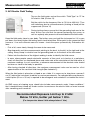
Measurement Instructions - AC Electric Fields
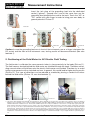
1. Grounding the Field Meter and the Person Performing the Testing
According to relevant guidelines (TCO, MPR II, TÜV), prior to any electric field testing the field
meter needs to be connected to ground potential through the supplied grounding lead in order to
obtain reliable, reproducible testing results. Without a proper connection to ground potential no
reliable statements on AC electric fields can be made.
Unvarnished, metal piping for water, gas or heating can be used
to connect the grounding lead with its grounding clip. As an alternative, a licensed electrician could also use an alligator clip to
establish a grounding connection through the grounding conductor in a grounded outlet. Warning: In case the phase conductor is
touched, an electric shock hazard may result.
Picture 06
© by GIGAHERTZ SOLUTIONS® GmbH, 90579 Langenzenn, www.gigahertz-solutions.com
9
R
GIGAHERTZ
SOLUTIONS
R
Measurement Instructions
Insert the jack plug of the grounding lead into the dedicated
socket ("ground", "ground icon") and at the same time run the
grounding lead alongside the case to the back. Touch the "AC" or
"DC" socket with your finger in order to bring your own body to
ground potential. Picture 07
Picture 07
Picture 08
Picture 09
Picture 10
Caution: In case the grounding lead runs in front of the instrument case or a finger is between the
DC socket and the front of the instrument case, testing results will become distorted. (See also
footnote 1)
2. Positioning of the Field Meter for AC Electric Field Testing
The field meter is calibrated for measurements taken in close proximity to the body (Picture 11).
The field sources located behind the field meter are shielded through the body. Therefore misleading concentrations of field lines onto the electric field sensor are avoided. Therefore try to avoid
taking measurements with a stretched-out arm. In general, this would lead to higher testing results
(Picture 12). This type of distortions can be reduced or avoided by placing a conductive surface
behind the field meter. (Picture 13, see also footnote 1)).
Picture 11
Picture 12
Picture 13
1) The electric field strength measured with ground reference always depends on the geometry of the field source and the sensor, the distance
between sensor and field source as well as ambient potentials. Following TCO guidelines, the ME 3951A is calibrated according to the TCOcalibrated field meter "Radians Innova - Enviromentor EMM-4 (Serial. No. 4348)" at a distance of 50 cm from a 4-sqm large copper plate operating at 50 Hz and 270 V. Instead of a person, which is also grounded during testing in the field, a grounded, square copper plate measuring
50 cm (ca. 20") on its sides is placed behind the field meter during calibration. The same procedure is recommended for reproducible tripod
measurements. Testing results of the ME 3951A can only be expected to correspond with those of an original TCO sensor when the distance
from the field plate is greater than 30 cm (12"). The measured field strength represents a spatial integral across the testing equipment, whose
simplification "measurement value in the direction of the highest display = resultant field strength" is a good approximation for practical purposes.
10
© by GIGAHERTZ SOLUTIONS® GmbH, 90579 Langenzenn, www.gigahertz-solutions.com
Measurement Instructions
GIGAHERTZ
SOLUTIONS
3. AC Electric Field Testing
Turn on the field meter and set the switch "Field Type" to "E" for
AC electric field. (Picture 14)
Set the switch for the frequency filter to "50 Hz to 400 kHz". Thus
self-inductions due to micromovements (shaking of hand) will be
suppressed. (Picture 14)
Picture 14
During testing always ensure that the grounding lead runs to the
back of the case and that the person performing the survey as
well as anybody else present are located behind the field meter.
Keep the field meter close to your body. The further away you hold the instrument or if it is even
put down, the falsely higher the testing results tend to become. Either point to the suspected field
source or - if no such concrete source is known - check the space systematically. Proceed as follows:
- First of all, move slowly through the room to be measured.
- Stop frequently and take measurements pointing to the back, to the left, to the right and to the
ceiling. Always keep in mind to have the grounding lead run to the back of the instrument.
- Follow into the direction of the highest reading in order to identify the field source.
- In areas where people spend substantial amounts of time such as in bed or at a workplace,
check all directions as mentioned above and make note of the orientation of the field meter at
maximum readings. In such a position, a reference measurement of the absolute value should
be taken as close to the body as possible.
- After having checked all directions, the maximum measurement value can be used as a first
approximation of the resultant field strength.(See footnote 1))
When the field meter is placed on a tripod or on a table, it is necessary to also place a person 5
cm (2") behind the instrument to obtain accurate measurements. For reproducible measurements,
a metal plate (50 cm x 50 cm) is required to be orthogonal and centered 5 cm behind the instrument.
An EMR survey of sleeping areas should also include measurements under "sleep conditions,"
that is bedside lamp turned off. Under certain circumstances the electric field can even increase
after something was turned off.
Recommended Exposure Limit up to 2 kHz:
Below 10 V/m, better yet below 1 V/m.
(For frequencies above 2 kHz always below 1 V/m)
© by GIGAHERTZ SOLUTIONS® GmbH, 90579 Langenzenn, www.gigahertz-solutions.com
11
R
GIGAHERTZ
SOLUTIONS
R
Measurement Instructions
AC Magnetic Field Testing:
Turn on the field meter and set the switch "Field Type" to "M" for
AC magnetic field. (Picture 15)
Set the switch for the frequency filter to "50 Hz to 400 kHz". Thus
self-inductions due to micromovements (shaking of hand) will be
suppressed. (Picture 15)
For reliable measurements of AC magnetic fields, neither the field
meter nor the person performing the measurements need to be
grounded. Other persons or mass potentials in the vicinity of the field meter do not affect the
testing results.
Picture 15
If a field source is suspected, point into that direction. Otherwise check the space systematically.
Proceed as follows:
-
First of all, move slowly through the room to be measured. The magnetic sensor is positioned
in such a way in the instrument that most typical field sources in residential settings are detected as long as the field meter is held horizontally. In addition, all three dimensions should be
checked from time to time as shown in the pictures 16 through 18.
-
In practice, the identification of a field source has proven to be most effective by locating the
direction of the highest reading first. Then you follow the direction, which continues to show
increasing measurement values. Simply keep the field meter aligned in the direction of the
maximum readings. For an accurate measurement, however, hold the instrument very steady
or put it down at a relevant measurement point.
- In the important places where we work, sit or sleep, all three dimensions of AC magnetic fields
should be checked each time. Proceed as follows.
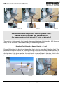
Accurate Measurement of the Magnetic Field Strength in the Presence of
Several Field Sources
In this event, it is necessary to take three separate measurements and write the readings down.
The field meter should be held as shown in the pictures: point to the front (Picture 16), to the ceiling (Picture 17) and to the side so that it is perpendicular to the front axis (Picture 18).
In order to estimate the resultant, that is the actual AC-magnetic-field exposure, the following rules
of thumb can be applied.
Rules of Thumb for Estimating the Total Magnetic Field Strength
Measurement Value:
Corresponding Total Magnetic Field :
- One high, two low values
~ Highest value
- Two high, one low value
~ Highest value + half of the second highest value
- Three similar values
~ One and a half times of the highest
12
© by GIGAHERTZ SOLUTIONS® GmbH, 90579 Langenzenn, www.gigahertz-solutions.com
GIGAHERTZ
SOLUTIONS
Measurement Instructions
Picture 16
Picture 17
Picture 18
Recommended Exposure Limit up to 2 kHz:
Below 200 nT, better yet below 20 nT.
(For frequencies above 2 kHz below 20 nT, better yet below 2 nT)
The resultant, total magnetic field strength (the sum of the single field strengths, 3-D Measurement) can be accurately calculated according to the following equation:
Resultant Field Strength = Square Root(x² + y² + z²)
Picture 19 illustrates the direction of the resultant field, which is also called "substitute field." The
photos for pictures 16 through 18, showing the single measurements of the three dimensions, as
well as picture 20 were taken in a kitchen during a typical testing session. If you would insert the
display values in the above equation, the result would come very close to the value, which is displayed in picture 20. There the field meter is held perpendicular to the resultant field.
x
Res.
y
z
Picture 19
© by GIGAHERTZ SOLUTIONS® GmbH, 90579 Langenzenn, www.gigahertz-solutions.com
Picture 20
13
R
GIGAHERTZ
SOLUTIONS
R
Measurement Instructions
Frequency Analysis (AC Electric and Magnetic Fields)
An AC electric or magnetic field is not only defined by its field strength, but also by the frequency
with which the polarity of the field changes. We encounter various common frequencies:
-
Overhead railway wires operate at 16.7 Hz (only in Europe).
-
The electric power grid (home wiring, high-tension power lines) operates at a 60-Hz frequency in North America and at a 50-Hz frequency in Europe. So-called natural harmonics are the
multiples of the respective fundamental frequency (50 Hz or 60 Hz).
-
In addition, various electronic devices are used in our homes that generate a variety of fields
with higher frequencies in the kHz range (artificial harmonics) such as switch-mode power
adapters ("transformers"), ballasts of fluorescent tubing and energy saving lamps as well as
dimmer switches with so-called switch mode technology and the like.
For the assessment of a certain area and especially with regards to appropriate remediation strategies, it is very useful to know how many of the different frequencies contribute to the total exposure. An exposure caused by overhead railway wires, for example, cannot be remedied by installations of the homeowner. However, it is possible to avoid certain signals of the kHz range by
choosing devices without such emissions (e.g. incandescent lamp instead of fluorescent tubing)
(only in Europe).
The ME 3951A field meter offers you different options to analyze frequencies:
Frequency Analysis with Frequency Filter Module F1B2H31
Picture 21
Picture 22
Depending on the testing situation, GIGAHERTZ SOLUTIONS® offers several different frequency filter modules for the ME 3951A. The Frequency Filter Module F1B2H31 (Picture 21/22) already supplied with the field meter is specifically designed for building biology needs. The following
frequencies can be selected:
1) 5 Hz to 400 kHz
=
Entire TCO frequency range, best suited for tripod measurements
2) 16.7 Hz
=
4th order band pass filter with Q-Factor 10 for the frequency of
overhead railway wires (only in Europe)
3) 50 Hz to 400 kHz
=
5th order high pass filter for the electric power grid and its harmonics
4) 2 kHz to 400 kHz
=
5th order high pass filter for so-called artificial harmonics above 2
kHz. This frequency range corresponds with band 2 of the Swedish
TCO guidelines.
In order to measure fields of overhead railway wires or harmonics, first the respective filter in the
14
© by GIGAHERTZ SOLUTIONS® GmbH, 90579 Langenzenn, www.gigahertz-solutions.com
Measurement Instructions
GIGAHERTZ
SOLUTIONS
field meter needs to be activated. Generally speaking, the testing follows the same principles as
described in the section "Measurement Instructions" for the fields of the power grid system. There
are only two points, which deserve special mention here:
-
Usually the source of the railway currents is located outside of a house. It is recommended,
nonetheless, that the entire house is roughly checked anyway because sometimes railway frequencies can also be found on, for example, water or gas piping as well as the electric wiring
system due to coupling effects. If a house to be tested is closer than 2 to 3 km to an electric
railway track, such potential sources should be checked to be on the safe side.
-
"Artificial" harmonics usually are less energetic than power or railway frequencies and therefore show lower testing results. For this frequency band, however, all renowned institutes recommend exposure limits that are 10 times lower than those for power frequency fields. Therefore
the frequency range "200 nT/Vm" is usually sufficient.
Note: Due to 1/f higher and white noise, filter tolerances, micromovements of the instrument and
frequencies beyond the filtered frequency bands, the testing results of the position "5 Hz to 400
kHz" can deviate from the sum of the filtered values.
Frequency Analysis via AC Output
Even in a "normal" work and living environment it is possible to encounter a great variety of frequencies in addition to the power frequency 60 Hz or 50 Hz, respectively. For a more detailed analysis of the different frequencies, a spectrum analyzer can be connected directly to the AC output
of the field meter by means of the supplied adapter. At the AC output a DC offset of maximum 50
mV is applied. It is standard in oscilloscopes and spectrum analyzers that this DC offset is usually suppressed by a capacitive coupling. In case the peripheral analysis instruments are connected
to the power grid including grounding conductor, the grounding of the field meter should not be
connected in order to avoid ground loops!
Following convention, the technical specifications of the field meter refer to the maximum values
given on the display, according to which the bandwidth of the AC output is limited to 30 kHz. If,
however, the measurement value is less than 1/20 of the maximum reading (e.g. in the measurement range 2000 nT this would equal 100 nT), there is still a sinusoidal input signal up to 400 kHz
with a non-linearity < 1% provided at the AC output. Since the field strengths in home and workplace settings often are in this range and not that much higher, this output can actually be used
up to 400 kHz then.
With a mono headset (adjustable volume is recommended) plugged into the AC socket, it is possible to perform a rough acoustic frequency analysis across the audible frequency range (ca. 16
Hz to 20 kHz). If needed, use adapter plug. The headset LS0002 is available as an accessory from
GIGAHERTZ SOLUTIONS®.
Data Logging via DC Output
The field strength of a given point in space often changes over a longer period of time. For a complete assessment, it is recommended to monitor the field strengths (DC values), for instance, for
24 hours. Therefore the field meter comes equipped with outputs where data logging and analy© by GIGAHERTZ SOLUTIONS® GmbH, 90579 Langenzenn, www.gigahertz-solutions.com
15
R
GIGAHERTZ
SOLUTIONS
R
Measurement Instructions
sis equipment can be connected. In general, the DC output (direct current output) is used for longterm monitoring with, for example, data loggers or data plotters.
Across the DC output a DC signal is applied, which is proportional to the measurement values. It
equals minus 0.5 mV per digit. That would, for example, translate into minus 1 Volt at a maximum
reading "2000 nT/Vm" or "200 nT/Vm". The negative signal was preferred over the positive signal
because it clearly offered better linearity and correspondence with the display value. Most analysis instruments can internally convert the input signal into the appropriate absolute value. If this is
not the case, simply reverse the polarity of the plug of the analysis instrument in order to display
positive values. When using the BNC adapter, the shielding of the testing lead is connected to
mass potential. Even though the maximum values of the display show either 2000 nT or 2000 V/m,
the DC signal at the DC output is actually still quite linear up to 5000 nT or 5000 V/m, respectively. The technical specifications of the field meter refer to the values shown as maximum values on
the display. As long as a jack plug is plugged into the DC socket, the "Auto-Power-Off" function
is deactivated in order to accommodate long-term data logging.
Caution: If during data logging the battery runs so low that "low Batt." is displayed, the "AutoPower-Off" function will be activated in order to prevent the battery from becoming completely
discharged, which otherwise might destroy the rechargeable battery.
24-hour data logging can be supported through a connection to the electric power system via the
adapter or a 12 V battery. In the event a power outage occurs during data logging, the rechargeable battery in the instrument will take over automatically. As soon as electric power comes back
on, the instrument will automatically switch back to the adapter. Place the adapter as far away
from the field meter as possible in order to keep the detection of its emissions as low as possible.
By making note of the field strength with and without having the adapter plugged into the outlet,
it is possible to calculate the correction value, which of course should be subtracted from the total
measurement values.
Changing Batteries
Opening the Case
Turn off the field meter and disconnect all extension cords plugged into it. Having the labeled side facing up toward you, hold the
field meter in your hand or put it down on a table.
Use the supplied wedge to open the case.
Picture 23
1.While opening the case, hold the instrument firmly in one hand
and with the other insert the wedge into the notch on the side,
about 1 cm (1/2") below the upper corner, and press the wedge
down on its thick end. There the lid will then lift slightly. Picture 23.
Picture 24
16
© by GIGAHERTZ SOLUTIONS® GmbH, 90579 Langenzenn, www.gigahertz-solutions.com
GIGAHERTZ
SOLUTIONS
Changing Batteries
2.The same procedure shall be repeated on the same side, but this
time about 1 cm (1/2") above the lower corner. Picture 24
Now the cover is open on one side.
Picture 25
3.Points 1 through 2 will also have to be repeated on the opposite
side. Pictures 25 and 26
Now the cover can be easily lifted off.
Picture 26
Closing the Case
Place the cover flush with the open field meter. Ensure that the
battery check button, the light diode and the frequency filter button all fit snugly into their designated openings in the cover. Using
thumbs and pointing fingers of both hands, press down on the
cover with a steady and gentle pressure. As a result, the cover will
snap into its place on both sides. Picture 27
Picture 27
Removing Batteries
Change batteries only while the instrument is turned off!
After having opened the cover, the rechargeable battery including
its clip can be removed or lifted out sideways.
In order to remove the battery clip from the rechargeable battery,
slip the small end of the wedge as far up between both contacts
as possible, then move the wide end of the wedge up and down.
Thus the clip can be easily detached. Picture 28
Picture 28
Under no circumstances ever pull at the leads or the plastic clip of the contacts; otherwise
they can easily be damaged or broken.
Inserting Batteries
Attach the new rechargeable battery to the battery clip and place it back into the battery compartment. While putting the battery back into the compartment, ensure that none of the battery
© by GIGAHERTZ SOLUTIONS® GmbH, 90579 Langenzenn, www.gigahertz-solutions.com
17
R
GIGAHERTZ
SOLUTIONS
R
Battery Management
leads will get trapped between the battery and some protruding part from the circuit board. In this
case you would be unable to slide the cover back properly.
In order to replace the supplied frequency filter with another one from GIGAHERTZ SOLUTIONS®, please follow the instructions enclosed with the new frequency filter.
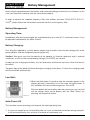
Battery Management
Operating Time:
Immediately after having recharged the supplied battery for a total of 11 continuous hours, it can
be operated continuously for about 8 hours.
Battery Charging:
First, plug the supplied or a similar power adapter into an outlet. Insert the low-voltage jack of the
power adapter into the designated socket (upper left).
Caution: Take great care that the polarity of the adapter ((+) internal conductor and (-) external
conductor) as well as the corresponding voltage (12-24 VDC) are correct!
In order to start charging the battery, turn on field meter and then off just once. After that leave it
turned off.
The green light of the diode will shine during the charging. After about 11 hours the charging mode
will be turned off automatically.
Low Batt.:
1. When the field meter is turned on and the two dots appear in the
display (low batt.), the battery is in a low state. Using the meter in
this condition will cause measuring errors. Picture 29
But even before the low-battery indicator comes on, you can find
out the charge status of the battery with the "Batt. Check" by
pressing the respective button.
Picture 29
Auto-Power-Off
This function conserves energy and extends the total operating time.
1. In case you forgot to turn off the field meter or it was accidentally turned on during transport,
it will be automatically shut off after 40 minutes of continuous use.
18
© by GIGAHERTZ SOLUTIONS® GmbH, 90579 Langenzenn, www.gigahertz-solutions.com
GIGAHERTZ
SOLUTIONS
Battery Management
2. When two dots appear in the center of the display (low batt.), the field meter will be turned off
after 3 min in order to protect the rechargeable battery from becoming completely discharged,
which would cause damage.
In order to turn on the field meter after an Auto-Power-Off, simply turn it off and on again.
Caution: If the DC signal output is connected, the normal Auto-Power-Off function is disabled.
This way it becomes possible to perform data logging supported by the rechargeable
battery, up to 8 hours. The low-battery shut-off, however, will kick in after 3 min just the
same in order to protect the rechargeable battery from the damages of a complete
(deep) discharge.
With an alkaline battery, it is possible to perform 24-hour data logging.
Caution: If an alkaline battery is being used, under no circumstances ever should the power
adapter be connected at the same time. Otherwise the battery may explode.
Checking Battery Status and Display-Check
Since the integrated rechargeable battery is not always charged
completely, it is possible to find out the remaining operating time
as well as the proper functioning of all display segments by pressing the "Batt.-Check" button.
Press the button!
1. In order to check the battery status, simply turn on the field meter,
press the button and continue to keep it pressed. If the display
shows "1999" or "1888," the instrument is optimally supplied with
power and all display elements function accurately. Picture 30.
Picture 30
2. When the instrument is turned on and the low battery button is
pressed, “low batt.” in the center of the display indicate that under
normal conditions the operating time will be less than 1 hour.
Picture 31
Press the button!
If need should be, recharge battery or turn off field meter.
Picture 31
Contact:
Gigahertz Solutions GmbH
Am Galgenberg 12
D - 90579 Langenzenn
Germany
Phone +49 (9101) 9093-0
Fax +49 (9101) 9093-23
www.gigahertz-solutions.com
For your local distributor please contact
www.gigahertz-solutions.com
© by GIGAHERTZ SOLUTIONS® GmbH, 90579 Langenzenn, www.gigahertz-solutions.com
19
R
GIGAHERTZ
SOLUTIONS
R
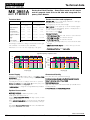
Technical data
ME 3951A
Professional Dual Function - Gauss/Tesla meter for AC electric
and AC magnetic fields 5 Hz to 400 kHz with integrated Frequency Filter Module
mit F1B2H31
Technical data
Frequency Range
Further functions and equipment
magnetic flux density
electric field strength
one dimension in nT/mG
against ground potential in V/m
5 Hz to 400 kHz
5 Hz to 400 kHz
(-1 dB limit)
(-1 dB limit)
3.5-digit LCD easy to read display, indication of field type
being measured and low Batt.
Tone signal proportional to field strength.
200,0 nT
2000 nT
200,0 V/m
2000 V/m
Resolution*
0,1 nT
1 nT
0,1 V/m
1 V/m
Signal outputs for AC-signals up to 30 kHz and DC-signals.
To connect for ex. data loggings, plotters or head phones for
acoustic frequency analysis.
basic tolerance*
±2%
±2%
±2%
±2%
Test mode to correct Offset.
± 0,3 nT
± 3 nT
± 0,2 V/m
± 0,2 V/m
± 0,4 nT
± 4 nT
± 0,4 V/m
± 0,4 V/m
Range Selection
(50 Hz tracable calibrated normal)
Linearity Deviation*
(at 50 Hz)
Instrument Contents:
· 16 Hz band pass filter 4th order, Q-Factor 10, be selected
Offset*
(at 50 Hz)
Power Supply
15 - 20 mA, according to the mode of operation
* At 20°C and 45% of the relative air humidity
Measuring procedures according to the international. Recognized standards of workstations (TCO and MPR).
Dimensions 74 x 122 x 31 mm, weight appr. 196 grams.
· 50 Hz high pass filter 5th order, be selected
· 2 kHz high pass filter 5th order, be selected
· High flexible grounding lead (5 m) to measure electric field
strength.
· BNC measurement adapter to connect with a spectru analyzer
· Detailed spezifications and user’s guide
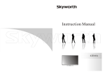
Typical frequency response curve
ohne_Filter 100,0V/m
electric field strength
[V/m]
120
Filter 1 100,0V/m
Filter 2 100,0V/m
Filter 3 100,0V/m
-1dB 100,0V/m
-3dB 100,0V/m
magnetic flux density
[nT]
100
80
60
40
20
0
1
10
100
1000
10000
frequency [Hz]
ohne_Filter 500nT
600
Power Supply
Filter 2 500nT
Filter 3 500nT
-1dB 500nT
-3dB 500nT
500
400
300
200
100
0
1
100000 1000000
Filter 1 500nT
10
100
1000
10000
frequency [Hz]
100000 1000000
Guaranteed Quality
Integrated rechargeable battery with a soft battery charge Innovative electronics, patented technology.
management, to protect from becoming completely dischar- Durable precession through self calibrating circuit elements.
ged or overcharged.
Made in Germany, state of the art SMD
Operating time 8 hours according to the mode of operation.
Manufacturing process.
Battery low indicator and auto power off function (auto power
High end components, FR4 material and reproducible manuoff is not active when data logging).
facturing methods.
12 VDC adapter to charge the rechargeable battery included.
2 Years Warranty on manufacturing defects.
Optional Accessories
Calibrating Certificate ( calibration periode: 1 year).
Stable plastic box with protectors.
External extra rechargeable battery with high capacity for data
loggings (> 48 hours)
Extra, external Display Meter to measure in areas with difficult
or no entries or for observation the measurement by a 2nd person.
Retrofitable Frequency Filter Modul with extra switchable limiting frequencies.
DRU0147a KW482006
20
© by GIGAHERTZ SOLUTIONS GmbH, 90579 Langenzenn, www.gigahertz-solutions.com
®