1
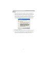
Motherboard User’s Guide This publication, including photographs, illustrations and software, is under the protection of international copyright laws, with all rights reserved. Neither this guide, nor any of the material contained herein, may be reproduced without the express written consent of the manufacturer. The information in this document is subject to change without notice. The manufacturer makes no representations or warranties with respect to the contents hereof and specifically disclaims any implied warranties of merchantability or fitness for any particular purpose. Further, the manufacturer reserves the right to revise this publication and to make changes from time to time in the content hereof without obligation of the manufacturer to notify any person of such revision or changes. Trademarks IBM, VGA, and PS/2 are registered trademarks of International Business Machines. AMD, Duron and Athlon are registered trademarks of Advanced Micro Devices Inc. Microsoft, MS-DOS and Windows 98/ME/2000/XP are registered trademarks of Microsoft Corporation. AMI is a registered trademark of American Megatrends Inc. Other names used in this publication may be trademarks and are acknowledged. Static Electricity Precautions 1. Do not take this motherboard and components out of their original staticproof package until you are ready to install them. 2. While installing, please wear a grounded wrist strap if possible. If you do not have a wrist strap, discharge static electricity by touching the bare metal of the system chassis. 3. Carefully hold this motherboard by its edges. Do not touch those components unless it is absolutely necessary. Put this motherboard on the top of static-protection package with component side facing up while installing. Pre-Installation Inspection 1. Inspect this motherboard whether there are any damages to components and connectors on the board. 2. If you suspect this motherboard has been damaged, do not connect power to the system. Contact your motherboard vendor about those damages. Copyright 2006 All Rights Reserved PCxx00 Series, V1.0 May 2006 i Motherboard User’s Guide Table of Contents Trademark ............................................................................................................ i Chapter 1: Introduction ..................................................................................... 1 Key Features .................................................................................................................... 1 Package Contents ........................................................................................................... 4 Chapter 2: Motherboard Installation .............................................................. 5 Motherboard Components ............................................................................................ 6 I/O Ports .......................................................................................................................... 7 Installing Memory Modules .......................................................................................... 8 Jumper Settings .............................................................................................................. 9 Install the Motherboard ............................................................................................... 1 0 Connecting Optional Devices ..................................................................................... 11 Install Other Devices .................................................................................................... 1 3 Expansion Slots ............................................................................................................ 1 5 Chapter 3: BIOS Setup Utility ....................................................................... 17 Introduction .................................................................................................................. 1 7 Running the Setup Utility................................................................................... 17 Standard CMOS Setup Page ....................................................................................... 1 8 Advanced BIOS Features Page .................................................................................. 1 9 Advanced Chipset Features Page ............................................................................... 2 2 Integrated Peripherals ................................................................................................. 2 6 Power Management Setup Page ................................................................................ 3 0 PCI/Plug and Play Setup Page .................................................................................. 3 4 PC Health Satus Page ................................................................................................. 3 5 Frequency/Voltage Control Page ............................................................................... 3 6 Load Fail-Safe Defaults .............................................................................................. 3 7 Load Optimized Defaults ............................................................................................. 3 7 Set Supervisor Password .............................................................................................. 3 7 Set User Password ........................................................................................................ 3 7 Save & Exit Setup ......................................................................................................... 3 8 Exit Without Saving ...................................................................................................... 3 8 Chapter 4: Software & Applications .............................................................. 39 Introduction .................................................................................................................. 3 9 Installing Support Software ........................................................................................ 3 9 Bundled Software Installation .................................................................................... 4 1 ii Motherboard User’s Guide Notice: 1. Owing to Microsoft certifying schedule is various to every supplier, we might have some drivers not certified yet by Microsoft. Therefore, it might happen under Windows XP that a dialogue box (shown as below) pops out warning you this software has not passed Windows Logo testing to verify its compatibility with Windows XP. Please rest assured that our RD department has already tested and verified these drivers. Just click the Continue Anyway button and go ahead the installation. 2. USB 2.0 Driver Limitations: 2-1. The USB 2.0 driver only supports Windows XP and Windows 2000. 2-2. If you connect a USB 2.0 hub to the root hub, plugging USB devices into this hub, the system might not successfully execute certain USB devices connection because it could not recognize these devices. iii Motherboard User’s Guide Chapter 1 Introduction This motherboard has onboard PCxx00 processor with front-side bus speed 400 MHz. This motherboard integrates the VIA CN700 Northbridge and VT8237R Plus Southbridge that supports the Serial ATA interface for high-performance and mainstream desktop PCs, and the built-in USB 2.0 providing higher bandwidth. It implements Universal Serial Bus Specification Revision 2.0. It supports 6-channel AC97 Audio Codec and provides one IDE Ultra DMA 133/ 100/66 channel. It has two 32-bit PCI slots, one CNR (Communications and Networking Riser) slot (Optional), and supports the onboard 10Base-T/100BaseTX Network interface (Optional). In addition, this motherboard has a full set of I/ O ports including two PS/2 ports for mouse and keyboard, one serial port, one parallel port, one LAN port (optional), four back-panel USB 2.0 ports, and three audio jacks for microphone, line-in and line-out. Onboard USB header(s) can provide extra ports by connecting the Extended USB Module to the motherboard. This motherboard is an Micro ATX size motherboard and has power connectors for an ATX power supply. Key Features The key features of this motherboard include: PCxx00 Processor Support • Supports onboard PCxx00 processor Chipset There are VIA CN700 Northbridge and VT8237R Plus Southbridge in this chipset in accordance with an innovative and scalable architecture with proven reliability and performance. • Defines Highly Integrated Solutions for Value Embedded PC Designs -High-performance UMA Northbridge that supports integrated PCxx00 Northbridge with 533 MHz FSB and UniChrome Pro 3D/2D Graphics & Video Controllers in a single chip • High Bandwidth 533 MB/sec 8-bit V-Link Host Controller -- Supports 66 MHz, 8X/4X transfer modes, V-Link interface with 533 MB/sec total bandwidth • Advanced System Power Management Support -- ACPI 2.0 and PCI Bus Power Management 1.1 compliant 1 Motherboard Users Guide • • • • PCI to system memory data streaming up to 132 Mbyte/sec (data sent to north bridge via high speed Ultra V-Link interface) PCI-2.2 compliant, 32-bit 3.3V PCI interface with 5V tolerant inputs Support six PCI slots of arbitration and decoding for all integrated functions and LPC bus. Dual Channel Serial ATA/RAID Controller—Complies with Serial ATA Specification Revision 1.0 Memory Support • Two 240-pin DIMM sockets for DDR2 SDRAM single channel memory modules • Supports DDR2 533/400 memory bus • Maximum installed memory is 2 GB Expansion Slots • One CNR slot (Optional) • Two 32-bit PCI slots Onboard IDE channels • Two IDE Connectors • Supports PIO (Programmable Input/Output) and DMA (Direct Memory Access) modes • Supports IDE Ultra DMA bus mastering with transfer rates of 133/100/66 MB/sec Serial ATA (Optional) • Two Serial ATA Connectors • Transfer rate exceeding best ATA (~1.5 Gb/s) with scalability to higher rates • Low pin count for both host and devices AC97 Codec • Compliant with AC97 2.3 specification • 16-bit Stereo full-duplex CODEC with independent and variable sampling rate • Support for 3.3v digital, 5v analog power supply and low power consumption management • Three analog line-level stereo inputs with 5-bit volume control: LINE_IN, CD, AUX • Front-Out, Surround-Out, MIC-In and LINE-In Jack Sensing • Two analog line-level mono input • Standard 48-Pin LQFP 2 Chapter 1: Introduction Onboard I/O Ports • Two PS/2 ports for mouse and keyboard • One serial port • One parallel port • One VGA port • Four back-panel USB2.0 ports • One LAN port (Optional) • Audio jacks for microphone, line-in and line-out Fast Ethernet LAN (Optional) • Built-in 100Base-TX/10Base-T Physical Layer solution • Dual Speed -- 100/10 Mbps • MII Interface to Ethernet Controller and Configuration & Status • Auto Negotiation: 10/100, Full/Half Duplex • Meet All applicable IEEE 802.3/802.3u, 10Base-T and 100 Base-TX Standards USB 2.0 • Compliant with Universal Serial Bus Specification Revision 2.0 • Compliant with Intel Enhanced Host Controller Interface Specification Revision 1.0 • Compliant with Universal Host Controller Interface Specification Revision 1.1 • Support PCI-Bus Power Management Interface Specification release 1.1 • Legacy support for all downstream facing ports BIOS Firmware This motherboard uses Award BIOS that enables users to configure many system features including the following: • Power management • Wake-up alarms • CPU parameters and memory timing • CPU and memory timing The firmware can also be used to set parameters for different processor clock speeds. Dimensions • Micro ATX form factor of 228 x 190 mm Note: Hardware specifications and software items are subject to change without notification. 3 Motherboard Users Guide Package Contents Your motherboard package ships with the following items: The motherboard Two IDE drive ribbon cable The Software support CD The I/O Shield 4 Chapter 2: Motherboard Installation Chapter 2 Motherboard Installation To install this motherboard in a system, please follow these instructions in this chapter: Identify the motherboard components Install one or more system memory modules Make sure all jumpers and switches are set correctly Install this motherboard in a system chassis (case) Connect any extension brackets or cables to headers/connectors on the motherboard Install peripheral devices and make the appropriate connections to headers/connectors on the motherboard Note: 1 2 Before installing this motherboard, make sure jumper CLR_CMOS1 is under Normal setting. See this chapter for information about locating CLR_CMOS1 and the setting options. Never connect power to the system during installation; otherwise, it may damage the motherboard. 5 Motherboard Users Guide Motherboard Components ITEM LABEL 1 PWR2 2 CPU_FAN1 3 DDRII1~2 COMPONENTS Standard 4-Pin ATX Pow er connector CPU Fan connector (3PIN) 240-pin DDR2 SDRAM sockets 4 PWR1 Standard 20-Pin ATX Pow er connector 5 IDE1 Primary IDE connector 6 IDE2 Secondary IDE connector 7 SPK1 Speaker header 8 SATA1/2 Serial ATA connectors (Optional) 9 PANEL1 Front Panel Sw itch/LED header 10 CLR_CMOS1 Clear CMOS jumper 11 SYS_FAN1 System Fan connector 12 FDD1 Floppy Disk Drive connector (Optional) 13 F_USB1/2 Front Panel USB headers 14 CNR1 CNR slot (Optional) 15 F_AUDIO1 Front Panel Audio header 16 PCI1-2 32-bit PCI slots 17 CD_IN1 Analog Audio Input header 18 IR1 Infrared header 6 Chapter 2: Motherboard Installation I/O Ports The illustration below shows a side view of the built-in I/O ports on the motherboard. PS/2 Mouse Use the upper PS/2 port to connect a PS/2 pointing device. PS/2 Keyboard Use the lower PS/2 port to connect a PS/2 keyboard. Parallel Port (LPT1) Use the Parallel port to connect printers or other parallel communications devices. Serial Port (COM1) Use the COM port to connect serial devices such as mice or fax/modems. COM1 is identified by the system as COM1. VGA Port Use the VGA port to connect VGA devices. LAN Port (optional) Connect an RJ-45 jack to the LAN port to connect your computer to the Network. USB Ports Use the USB ports to connect USB devices. Audio Ports Use these three audio jacks to connect audio devices. The first jack is for stereo Line-In signal, the second jack for stereo Line-Out signal, and the third jack for Microphone. 7 Motherboard Users Guide Installing Memory Modules This motherboard accommodates two 240-pin DIMM sockets (Dual Inline Memory Module) for unbuffered DDR2 533/400 memory modules (Double Data Rate SDRAM), and maximum 2 GB installed memory. Over its predecessor, DDR-SDRAM, DDR2-SDRAM offers greater bandwidth and density in a smaller package along with a reduction in power consumption. In addition, DDR2-SDRAM offers new features and functions that enable a higher clock rate and data rate operations of 400 MHz, 533 MHz, 667 MHz, and above. DDR2 transfers 64 bits of data twice every clock cycle. Memory Module Installation Procedure These modules can be installed with up to 2 GB system memory. Refer to the following to install the memory module. 1. Push down the latches on both sides of the DIMM socket. 2. Align the memory module with the socket. There is a notch on the DIMM socket that you can install the DIMM module in the correct direction. Match the cutout on the DIMM module with the notch on the DIMM socket. 3. Install the DIMM module into the socket and press it firmly down until it is seated correctly. The socket latches are levered upwards and latch on to the edges of the DIMM. 4. Install any remaining DIMM modules. 8 Chapter 2: Motherboard Installation Jumper Settings Connecting two pins with a jumper cap is SHORT; removing a jumper cap from these pins, OPEN. CLR_CMOS1: Clear CMOS Jumper Use this jumper to clear the contents of the CMOS memory. You may need to clear the CMOS memory if the settings in the Setup Utility are incorrect and prevent your motherboard from operating. To clear the CMOS memory, disconnect all the power cables from the motherboard and then move the jumper cap into the CLEAR setting for a few seconds. Function Jum per Normal Short Pins 1-2 Clear CMOS Short Pins 2-3 Note: To avoid the system unstability after clearing CMOS, we recommend users to enter the main BIOS setting page to Load Optimal Defaults and then Save Changes and Exit. 9 Motherboard Users Guide Install The Motherboard Install the motherboard in a system chassis (case). The board is a Micro ATX size motherboard. You can install this motherboard in an ATX case. Make sure your case has an I/O cover plate matching the ports on this motherboard. Install the motherboard in a case. Follow the case manufacturer’s instructions to use the hardware and internal mounting points on the chassis. Connect the power connector from the power supply to the PWR1 connector on the motherboard. PWR2 is a +12V connecotr for CPU Vcore power. If there is a cooling fan installed in the system chassis, connect the cable from the cooling fan to the SYS_FAN1 fan power connector on the motherboard. Connect the case switches and indicator LEDs to the PANEL1 header. Pin 1 3 5 7 9 Signal HD_LED_P(+) HD_LED_N(-) RESET_SW_N(-) RESET_SW_P(+) RSVD_DNU Pin 2 4 6 8 10 10 Signal FP PWR/SLP(+) FP PWR/SLP(-) POWER_SW_P(+) POWER_SW_N(-) KEY Chapter 2: Motherboard Installation Connecting Optional Devices Refer to the following for information on connecting the motherboard optional devices: SPK1: Speaker Header Connect the cable from the PC speaker to the SPK1 header on the motherboard. Pin 1 2 3 4 Signal +5V NC GND SPKR F_AUDIO1: Front Panel Audio Header This header allows the user to install auxiliary front-oriented microphone and lineout ports for easier access. Pin 1 3 5 7 9 Signal AUD_MIC AUD_MIC_BIAS AUD_FPOUT_R HP_ON AUD_FPOUT_L Pin 2 4 6 8 10 11 Signal AUD_GND AUD_VCC AUD_RET_R KEY AUD_RET_L Motherboard Users Guide F_USB1~2: Front Panel USB Headers The motherboard has USB ports installed on the rear edge I/O port array. Additionally, some computer cases have USB ports at the front of the case. If you have this kind of case, use auxiliary USB headers F_USB1~2 to connect the front-mounted ports to the motherboard. Here is a list of USB pin assignments. Pin 1 3 5 7 9 Signal VERG_FP_USBPWR0 USB_FP_P0(-) USB_FP_P0(+) GROUND KEY Pin 2 4 6 8 10 Signal VERG_FP_USBPWR0 USB_FP_P1(-) USB_FP_P1(+) GROUND GROUND 1. Locate the F_USB1~2 headers on the motherboard. 2. Plug the bracket cable onto the F_USB1~2 headers. 3. Remove a slot cover from one of the expansion slots on the system chassis. Install an extension bracket in the opening. Secure the extension bracket to the chassis with a screw. IR1: Infrared Port Header The infrared port allows the wireless exchange of information between your computer and similarly equipped devices such as printers, laptops, Personal Digital Assistants (PDAs), and other computers. Pin 1 3 5 Signal NC +5V IRTX Pin 2 4 6 Signal KEY GND IRRX 1. Locate the infrared port-IR1 header on the motherboard. 2. If you are adding an infrared port, connect the ribbon cable from the port to the IR1 header and then secure the port to an appropriate place in your system chassis. 12 Chapter 2: Motherboard Installation Install Other Devices Install and connect any other devices in the system following the steps below. Floppy Disk Drive (Optional) The motherboard ships with a floppy disk drive cable that can support one or two drives. Drives can be 3.5" or 5.25" wide, with capacities of 360K, 720K, 1.2MB, 1.44MB, or 2.88MB. Install your drives and connect power from the system power supply. Use the cable provided to connect the drives to the floppy disk drive connector FDD1. IDE Devices IDE devices include hard disk drives, high-density diskette drives, and CD-ROM or DVD-ROM drives, among others. The mainboard ships with an IDE cable that can support one or two IDE devices. If you connect two devices to a single cable, you must configure one of the drives as Master and one of the drives as Slave. The documentation of the IDE device will tell you how to configure the device as a Master or Slave device. The Master device connects to the end of the cable. Install the device(s) and connect power from the system power supply. Use the cable provided to connect the device(s) to the Primary IDE channel connector IDE1 on the motherboard. 13 Motherboard Users Guide If you want to install more IDE devices, you can purchase a second IDE cable and connect one or two devices to the Secondary IDE channel connector IDE2 on the motherboard. If you have two devices on the cable, one must be Master and one must be Slave. Serial ATA Devices (Optional) The Serial ATA (Advanced Technology Attachment) is the standard interface for the IDE hard drives, which is designed to overcome the design limitations while enabling the storage interface to scale with the growing media rate demands of PC platforms. It provides you a faster transfer rate of 1.5 Gb/s. If you have installed a Serial ATA hard drive, you can connect the Serial ATA cables to the Serial ATA hard drive or the connector on the motherboard. On the motherboard, locate the Serial ATA connectors SATA1-2, which support new Serial ATA devices for the highest data transfer rates, simpler disk drive cabling and easier PC assembly. It eliminates limitations of the current Parallel ATA interface, but maintains register compatibility and software compatibility with Parallel ATA. Analog Audio Input Header If you have installed a CD-ROM drive or DVD-ROM drive, you can connect the drive audio cable to the onboard sound system. When you first start up your system, the BIOS should automatically detect your CD-ROM/DVD drive. If it doesn’t, enter the Setup Utility and configure the CDROM/DVD drive that you have installed. On the motherboard, locate the 4-pin header CD_IN1. 14 Chapter 2: Motherboard Installation Here is a list of CD_IN1 pin assignments. Pin 1 2 3 Signal CD IN L GND GND 4 CD IN R Expansion Slots This motherboard has one CNR and two 32-bit PCI slots. 15 Motherboard Users Guide Follow the steps below to install an CNR/PCI expansion card. 1. Locate the CNR or PCI slots on the mainboard. 2. Remove the blanking plate of the slot from the system chassis. 3. Install the edge connector of the expansion card into the slot. Ensure the edge connector is correctly seated in the slot. 4. Secure the metal bracket of the card to the system chassis with a screw. CNR Slot (Optional) You can install the CNR (Communications and Networking Riser) cards in this slot, including LAN, Modem, and Audio functions. PCI Slots You can install the 32-bit PCI interface expansion cards in the slots. 16 Chapter 3: BIOS Setup Utility Chapter 3 BIOS Setup Utility Introduction The BIOS Setup Utility records settings and information of your computer, such as date and time, the type of hardware installed, and various configuration settings. Your computer applies the information to initialize all the components when booting up and basic functions of coordination between system components. If the Setup Utility configuration is incorrect, it may cause the system to malfunction. It can even stop your computer booting properly. If it happens, you can use the clear CMOS jumper to clear the CMOS memory which has stored the configuration information; or you can hold down the Page Up key while rebooting your computer. Holding down the Page Up key also clears the setup information. You can run the setup utility and manually change the configuration. You might need to do this to configure some hardware installed in or connected to the motherboard, such as the CPU, system memory, disk drives, etc. Running the Setup Utility Every time you start your computer, a message appears on the screen before the operating system loading that prompts you to "Hit <DEL>if you want to run SETUP". Whenever you see this message, press the Delete key, and the Main menu page of the Setup Utility appears on your monitor. Phonex-AwardBIOS CMOS Setup Utility Standard CMOS Setup Advanced BIOS Features Advanced Chipset Features Integrated Peripherals Power Management Setup PCI / Plug and Play Setup PC Health Status Frequency/Voltage Control Load Fail-Safe Defaults Load Optimized Defaults Set Supervisor Password Set User Password Save & Exit Setup Exit Without Saving Esc: Quit F10: Save & Exit Setup : Select Item Change CPU’s Clock & Voltage You can use cursor arrow keys to highlight anyone of options on the main menu page. Press Enter to select the highlighted option. Press the Escape key to leave the setup utility. Press +/-/ to modify the selected field’s values. 17 Motherboard Users Guide Some options on the main menu page lead to tables of items with installed values that you can use cursor arrow keys to highlight one item, and press PgUp and PgDn keys to cycle through alternative values of that item. The other options on the main menu page lead to dialog boxes requiring your answer OK or Cancel by selecting the [OK] or [Cancel] key. If you have already changed the setup utility, press F10 to save those changes and exit the utility. Press F1 to display a screen describing all key functions. Press F9 to install the setup utility with a set of default values. Standard CMOS Setup Page This page displays a table of items defining basic information about your system. Phonex-AwardBIOS CMOS Setup Utility Standard CMOS Setup f f f f f f Date (mm:dd:yy) Time (hh:mm:ss) Wed, Jan. 1 2003 0 : 15 : 47 IDE IDE IDE IDE IDE IDE [ [ [ [ [ [ Channel Channel Channel Channel Channel Channel 0 0 1 1 2 3 Master Slave Master Slave Master Master None] None] None] None] None] None] Menu Level f Change the day, month, year and century Drive A [1.44M, 3.5 in.] Video Halt On [EGA/VGA] [All, But Keyboard] Base Memory Extended memory Total Memory Help Item 640K 456704K 457728K : Move Enter: Select +/-/PU/PD: Value F10: Save Esc: Exit F1: General Help F5: Previous Values F6: Fial-Safe Defaults F7: Optimized Defaults System Date & System Time These items set up system date and time. IDE Channel 0/1/2/3 Master & IDE Channel 0/1 Salve Use these items to configure devices connected to the Primary/Secondary IDE channels. To configure an IDE hard disk drive, choose Auto. If the Auto setting fails to find a hard disk drive, set it to User, and then fill in the hard disk characteristics (Size, Cyls, etc.) manually. If you have a CD-ROM drive, select the setting CDROM. If you have an ATAPI device with removable media (e.g. a ZIP drive or an LS-120), select Floptical. 18 Chapter 3: BIOS Setup Utility Drive A These items define the characteristics of any diskette drive attached to the system. You can connect one or two diskette drives. Video The item defines the video mode of the system. This motherboard has a built-in VGA graphics system; you must leave this item at the default value. Halt On This item defines the operation of the system POST (Power On Self Test) routine. You can use this item to select which types of errors in the POST are sufficient to halt the system. Base Memory, Extended Memory, and Total Memory These items are automatically detected by the system at start up time. These are display-only fields. You cannot make changes to these fields. Advanced BIOS Features Page This page sets up more advanced information about your system. Handle this page with caution. Any changes can affect the operation of your computer. [Press Enter] [Press Enter] [Enabled] [Enabled] [Enabled] [Floppy] [LS120] [CDROM] [Enabled] [Disabled] [Disabled] [On] [Disabled] 6 250 [Setup] [1.4] [Non-OS2] [Enabled] Help Item Menu Level f f f CPU Feature f Hard Disk Boot Priority CPU L1 & L2 Cache CPU L2 Cache ECC Checking Quick Power On Self Test First Boot Device Second Boot Device Third Boot Device Boot Other Device Swap Floppy Drive Boot Up Floppy Seek Boot Up NumLock Status Typematic Rate Setting X Typematic Rate (Chars/Sec) X Typematic Delay (Msec) Security Option MPS Version Control For OS OS Select For DRAM > 64 MB Video BIOS Shadow f Phonex-AwardBIOS CMOS Setup Utility Advanced BIOS Features : Move Enter: Select +/-/PU/PD: Value F10: Save Esc: Exit F1: General Help F5: Previous Values F6: Fial-Safe Defaults F7: Optimized Defaults 19 Motherboard Users Guide f CPU Feature (Press Enter) Scroll to this item and press <Enter> to view the following screen: Phonex-AwardBIOS CMOS Setup Utility CPU Feature Delay Prior to Thermal Help Item [16 Min] Menu Level ff : Move Enter: Select +/-/: Value F10: Save Esc: Exit F1: General Help F5: Previous Values F6: Fial-Safe Defaults F7: Optimized Defaults Delay Prior to Thermal (16 Min) This item enables you to set the delay time before the CPU enters auto thermal mode. f Hard Disk Boot Priority (Press Enter) Scroll to this item and press <Enter> to view the following screen: Phonex-AwardBIOS CMOS Setup Utility Hard Disk Boot Priority Help Item 1. Bootable Add-in Cards Menu Level ff Use <m > or <n > to select a device, then press <+> to move it up, or <-> to move it down the list. Press <ESC> to exit this menu. : Move Enter: Select +/-/PU/PD: Value F10: Save Esc: Exit F1: General Help F5: Previous Values F6: Fial-Safe Defaults F7: Optimized Defaults 20 Chapter 3: BIOS Setup Utility CPU L1 & L2 Cache All processors that can be installed in this motherboard use internal level 1 (L1) and external level 2 (L2) cache memory to improve performance. Leave this item at the default value for better performance. CPU L2 Cache ECC Checking Enable this item to allow CPU L2 Cache ECC (Error Correcting Code) checking. Quick Power On Self Test Enable this item to shorten the power on testing (POST) and have your system start up faster. You might like to enable this item after you are confident that your system hardware is operating smoothly. First/Second/Third Boot Device Use these three items to select the priority and order of the devices that your system searches for an operating system at start-up time. Boot Other Device When enabled, the system searches all other possible locations for an operating system if it fails to find one in the devices specified under the First, Second, and Third boot devices. Swap Floppy Drive If you have two floppy diskette drives in your system, this item allows you to swap the assigned drive letters so that drive A becomes drive B, and drive B becomes drive A. Boot Up Floppy Seek If this item is enabled, it checks the size of the floppy disk drives at start-up time. You do not need to enable this item unless you have a legacy diskette drive with 360K capacity. Boot Up NumLock Status This item defines if the keyboard Num Lock key is active when your system is started. Typematic Rate Setting (Disabled) If this item is enabled, you can use the following two items to set the typematic rate and the typematic delay settings for your keyboard. • Typematic Rate (Chars/Sec): Use this item to define how many char- • Typematic Delay (Msec): Use this item to define how many millisec- acters per second are generated by a held-down key. onds must elapse before a held-down key begins generating repeat characters. 21 Motherboard Users Guide Security Option If you have installed password protection, this item defines if the password is required at system start up, or if it is only required when a user tries to enter the Setup Utility. MPS Version Control For OS This item specifies which version of MPS (Multi-Processor Specification) this motherboard will use. Leave this item to its default setting. OS Select For DRAM > 64 MB This item is only required if you have installed more than 64 MB of memory and you are running the OS/2 operating system. Otherwise, leave this item at the default. Video BIOS Shadow Enable this item to shadow basic BIOS function in ROM in order to invoke these functions whenever needs. Small Logo (EPA) Show Enables or disables the display of the EPA logo during boot. Advanced Chipset Features Page These items define critical timing parameters of the motherboard. You should leave the items on this page at their default values unless you are very familiar with the technical specifications of your system hardware. If you change the values incorrectly, you may introduce fatal errors or recurring instability into your system. Phonex-AwardBIOS CMOS Setup Utility Advanced Chipset Features f DRAM Clock/Drive Control f AGP & P2P Bridge Control f CPU & PCI Bus Control System BIOS Cacheable Video RAM Cacheable [Press Enter] [Press Enter] [Press Enter] [Disabled] [Disabled] Help Item Menu Level f : Move Enter: Select +/-/PU/PD: Value F10: Save Esc: Exit F1: General Help F5: Previous Values F6: Fial-Safe Defaults F7: Optimized Defaults 22 Chapter 3: BIOS Setup Utility f DRAM Clock/Drive Control (Press Enter) Scroll to this item and press <Enter> to view the following screen: Phonex-AwardBIOS CMOS Setup Utility DRAM Clock/Drive Control x x x x x x x x Current FSB Frequency 100MHz Current DRAM Frequency 266MHz DRAM Clock [By SPD] DRAM Timing [Auto By SPD] SDRAM CAS Latency [DDR/DDR 2.5/4 Bank Interleave Disabled Precharge to Active (Trp) 4T Active to Precharge (Tras) 07T Active to CMD (Trfc) 4T REF to ACT/REF (Trfc) 21T ACT (0) ACT (1) (TRRD) 3T Read to Precharge (Trtp) [2T] Write to Read CMD (Twtr) [1T/2T] Write Recovery Time (Twr) [4T] DRAM Command Rate [2T Command] RDSAIT mode [Auto] RDSAIT selection 03 Help Item Menu Level ff : Move Enter: Select +/-/: Value F10: Save Esc: Exit F1: General Help F5: Previous Values F6: Fial-Safe Defaults F7: Optimized Defaults Current FSB/DRAM Frequency This item displays current FSB/DRAM frequency. DRAM Clock This item sets the DRAM clock module. DRAM Timing This item selects the DRAM timing mode. • SDRAM CAS latency This item determines the operation of DDR SDRAM memory CAS (column address strobe). It is recommended that you leave this item at the default value. The 2.5T setting requires faster memory that secifically supports this mode. • Bank Interleave: Depending on your SDRAM module structure, the 4Way setting can offer the best performance. If you choose the wrong setting, the computer system will not run in a stable number. • Precharge to Active (Trp): This item specifies the the amount of time from a bank precharge request to when it can be activated. It is usually recommended you use the lowest Trp which your RAM and motherboard can run stable with. • Active to Precharge (Tras): This item specifies the the amount of time required between an active command to a precharge command. • • REF to ACT/REF (Trfc): This item means AutoRefresh period. ACT (0) to ACT(1) (TRRD): This item means ACT (0) to ACT(1) delay. 23 Motherboard Users Guide Read to Precharge (Trtp) This item defines the precharge operation always starts one clock following the Read command, independent of CAS Latancy. Write to Read CMD This item species CMD between a valid write command and the next read command. Write Recovery Time Use this item to specify the time measured from the last write datum is safely registered by the DRAM. DRAM Command Rate When the host (northbridge locates the desired memory address, it then processors the wait state of commands. RDSAIT mode This item enable or disable the RDSAIT mode. RDSAIT selection This item enable or disable to select the RDSAIT mode. f AGP & P2P Bridge Control (Press Enter) Scroll to this item and press <Enter> to view the following screen: Phonex-AwardBIOS CMOS Setup Utility AGP & P2P Bridge Control Help Item AGP Aperture Size [128M] AGP3.0 Mode [8X] AGP Driving Control [Auto] AGP Driving Value DA AGP Fast Write [Disabled] AGP Master 1 WS Write [Enabled] AGP Master 1 WS Read [Enabled] AGP 3.0 Calibration cycle [Disabled] TotalMemory with VGA memor[64M] Direct Frame Buffer [Enabled] Menu Level ff : Move Enter: Select +/-/: Value F10: Save Esc: Exit F1: General Help F5: Previous Values F6: Fial-Safe Defaults F7: Optimized Defaults 24 Chapter 3: BIOS Setup Utility AGP Aperture Size This item defines the size of the aperture if you use an AGP graphics adapter. The AGP aperture refers to a section of the PCI memory addres range used for graphics memory. We recommend that you leave this item at default value. AGP 3.0 Mode This item defines the AGP 3.0 mode. AGP Driving Control Use this item to set AGP driving work mode. AGP Driving Value Use this item to control AGP driving computation way. Only when AGP Driving Control is enabled. AGP Fast Write Use this item to enable or disable AGP Fast Write function. Enable this item to improve AGP efficiency. AGP Master 1 WS Write/Read Disable this item to make AGP Master delay the operation of data write/read. f CPU & PCI Bus Control (Press Enter) Scroll to this item and press <Enter> to view the following screen: Phonex-AwardBIOS CMOS Setup Utility CPU & PCI Bus Control PCI Master 0 WS Write PCI Delay Transaction VLink mode selection VLink 8X Support DRDY_Timing Help Item [Enabled] [Enabled] [By Auto] [Enabled] [Default] Menu Level ff : Move Enter: Select +/-/PU/PD: Value F10: Save Esc: Exit F1: General Help F5: Previous Values F6: Fial-Safe Defaults F7: Optimized Defaults 25 Motherboard Users Guide PCI Master 0 WS Write This item determines whether the chipsets inserts a delay before any writes from the PCI slots. If it is enabled, write requests to the PCI bus are executed immediately (with zero wait states), if the PCI bus is ready to send data. PCI Delay Transaction This item is used to meet the latency of PCI cycles to and from the ISA bus. VLink mode selection This item controls the data transfer speed between the north and south bridge. VLink 8X Support Use this item to enable or disable VLink 8X support. DRDY_Timing This item specifies the timing of data ready. System BIOS Cacheable Enable this item to get faster system BIOS executing speed via the L2 cache. Video RAM Cacheable Disable or enable this item to read cache data from RAM. Integrated Peripherals Page These options display items that define the operation of peripheral components on the system’s input/output ports. Phonex-AwardBIOS CMOS Setup Utility Integrated Peripherals f VIA OnChip IDE Device f VIA OnChip PCI Device f Super IO Device Help Item [Press Enter] [Press Enter] [Press Enter] Menu Level f : Move Enter: Select +/-/: Value F10: Save Esc: Exit F1: General Help F5: Previous Values F6: Fial-Safe Defaults F7: Optimized Defaults 26 Chapter 3: BIOS Setup Utility X VIA OnChip IDE Device (Press Enter) Scroll to this item and press <Enter> to view the following screen: Phonex-AwardBIOS CMOS Setup Utility VIA OnChip IDE Device OnChip IDE SATA SATA Mode IDE DMA transfer access OnChip IDE Channel 0 OnChip IDE Channel 1 IDE Prefetch Mode Primary Master PIO Primary Slave PIO Secondary Master PIO Secondary Slave PIO Primary Maste UDMA Primary Slave UDMA Secondary Master UDMA Secondary Slave UDMA IDE HDD Block Mode [Enabled] [IDE] [Enabled] [Enabled] [Enabled] [Enabled] [Auto] [Auto] [Auto] [Auto] [Auto] [Auto] [Auto] [Auto] [Enabled] Help Item Menu Level f : Move Enter: Select +/-/PU/PD: Value F10: Save Esc: Exit F1: General Help F5: Previous Values F6: Fial-Safe Defaults F7: Optimized Defaults OnChip SATA Use these items to enable or disable the PCI IDE channels that are integrated on the motherboard. SATA Mode This item defines the onboard SATA mode. IDE DMA transfer access This item allows you to enable the transfer access of the IDE DMA then burst onto the PCI bus and nonburstable transactions do not. OnChip IDE Channel 0/1 This item allow you to enable or disable the onboard IDE channels. IDE Prefetch Mode The onboard IDE drive interface supports IDE prefetching, for faster drive access. If you install a primary and secondary add-in IDE interface, set this field to Disabled if the interface does not support prefetching. Primary/Secondary Master/Slave PIO Each IDE channel supports a master device and a slave device. These four items let you assign the kind of PIO (Programmed Input/Output) was used by the IDE devices. Choose Auto to let the system auto detect which PIO mode is best, or select a PIO mode from 0-4. 27 Motherboard Users Guide Primary/Secondary Master/Slave UDMA Each IDE channel supports a master device and a slave device. This motherboard supports UltraDMA technology, which provides faster access to IDE devices. If you install a device that supports UltraDMA, change the appropriate item on this list to Auto. You may have to install the UltraDMA driver supplied with this motherboard in order to use an UltraDMA device. IDE HDD Block Mode Block mode is also called block transfer, multiple commands, or multiple sector read/write. If your IDE hard drive supports block mode, select Enabled for automatic detection of the optimal number of block read/write per sector the drive can support. fVIA OnChip PCI Device (Press Enter) Scroll to this item and press <Enter> to view the following screen: Phonex-AwardBIOS CMOS Setup Utility VIA OnChip PCI Device AC97 Audio MC97 Modem OnBoard LAN Device Onboard Lan Boot ROM OnChip USB Controller OnChip EHCI Controller USB Emulation x USB Keyboard Support x USB Mouse Support Help Item [Auto] [Auto] [Enabled] [Disabled] [All Enabled] [Enabled] [ON] Enabled Enabled Menu Level ff : Move Enter: Select +/-/PU/PD: Value F10: Save Esc: Exit F1: General Help F5: Previous Values F6: Fial-Safe Defaults F7: Optimized Defaults AC97 Audio Enables and disables the onboard audio chip. Disable this item if you are going to install a PCI audio add-in card. MC97 Modem Enable and disable the onboard MC97 modem. Onboard LAN Device Enable or disable the Onboard Lan function. Onboard Lan Boot ROM Enable and disable the booting from the onboard LAN or a network add-in card with a remote boot ROM installed. 28 Chapter 3: BIOS Setup Utility Onchip USB Controller This item enables users to enable or disable the onchip USB function, setting it to be USB1.1 or USB2.0 compatible. OnChip EHCI Controller Enable or disable the Onboard EHCI controller. USB Emulation This item enables and disables the USB emulation. USB Keyboard Support Enables this item if you plan to use a keyboard connected through the USB port in a legacy operating system (such as DOS) that does not support Plug and Play. USB Mouse Support Enable this item if you plan to use a mouse connected through the USB port in a legacy operating system (such as DOS) that does not support Plug and Play. X SuperIO Device (Press Enter) Scroll to this item and press <Enter> to view the following screen: Phonex-AwardBIOS CMOS Setup Utility SuperIO Device Onboard FDC Controller Onboard Serial Port 1 UART Port x UART Mode Select x UR2 Duplex Mode Onboard Parallel Port Parallel Port Mode x ECP Mode Use DMA [Enabled] [3F8/IRQ4] [Disabled] IrDA Full [378/IRQ7] [Normal] 3 Help Item Menu Level f : Move Enter: Select +/-/PU/PD: Value F10: Save Esc: Exit F1: General Help F5: Previous Values F6: Fial-Safe Defaults F7: Optimized Defaults Onboard FDC Controller (Enabled) This option enables the onboard floppy disk drive controller. Onboard Serial Port 1 (3F8/IRQ4) This option is used to assign the I/O address and interrupt request (IRQ) for onboard serial port 1/2. UART Port This item allows users to enable or disable the UART 2 Mode Controller. 29 Motherboard Users Guide • UART Mode Select (IrDA): This field enables you to select the infrared communication protocol-Normal (default), IrDA, or ASKIR. • UR2 Duplex Mode (Full): This field is available when UART Mode is set to either ASKIR or IrDA. This item enables you to determine the infrared function of the onboard infrared chip. The options are Full and Half (default). Full-duplex means that you can transmit and send information simultaneously. Half-duplex is the transmission of data in both directions, but only one direction at a time. Onboard Parallel Port This option is used to assign the I/O address and interrupt request (IRQ) for the onboard parallel port. Parallel Port Mode Enables you to set the data transfer protocol for your parallel port. There are four options: SPP (Standard Parallel Port), EPP (Enhanced Parallel Port), ECP (Extended Capabilities Port) and ECP+EPP. SPP allows data output only. Extended Capabilities Port (ECP) and Enhanced Parallel Port (EPP) are bi-directional modes, allowing both data input and output. ECP and EPP modes are only supported with EPP- and ECP-aware peripherals. ECP Mode Use DMA When the onboard parallel port is set to ECP mode, the parallel port can use DMA 3 or DMA 1. Power Management Setup Page This option lets you control system power management. The system has various power-saving modes including powering down the hard disk, turning off the video, suspending to RAM, and software power down that allows the system to be automatically resumed by certain events. Phonex-AwardBIOS CMOS Setup Utility Power Management Setup ACPI function ACPI Enhanced Efficiency HDD Power Down Suspend Mode Video Off Option Video Off Method MODEM Use IRQ Soft-Off by PWRBTN Run VGABIOS if S3 Resume Power on After Power Fail f IRQ/Event Activity Detect [Enabled] [Enabled] [Disabled] [Disabled] [Suspend -> Off] [V/H SYNC + Blank] [3] [Instant-Off] [Auto] [Off] [Press Enter] Help Item Menu Level f : Move Enter: Select +/-/PU/PD: Value F10: Save Esc: Exit F1: General Help F5: Previous Values F6: Fial-Safe Defaults F7: Optimized Defaults 30 Chapter 3: BIOS Setup Utility ACPI function Use this item toenable ACPI (Advanced Configuration and Power Management Interface) function. ACPI Enhanced Efficiency This item allows you to enable or disable ACPI Enhanced Efficiency function. HDD Power Down The IDE hard drive will spin down if it is not accessed within a specified length of time. Suspend Mode The CPU clock will be stopped and the video signal will be suspended if no Power Management events occur for a specified length of time. Full power function will return when a Power Management events is detected. Video Off Option This item defines if the video is powered down when the system is put into suspend mode. Video Off Method This item defines how the video is powered down to save power. This item is set to DPMS (Display Power Management Software) by default. MODEM Use IRQ If you want an incoming call on a modem to automatically resume the system from a power saving mode, use this item to specify the interrupt request line (IRQ) that is used by the modem. You might have to connect the fax/modem to the motherboard Wake On Modem. Soft-Off by PWRBTN Under ACPI (Advanced Configuration and Power management Interface) you can create a software power down. In a software power down, the system can be resumed by Wake Up Alarms. This item lets you install a software power down that is controlled by the power button on your system. If the item is set to Instant-Off, then the power button causes a software power down. If the item is set to Delay 4 Sec. then you have to hold the power button down for four seconds to cause a software power down. Run VGABIOS if S3 Resume Use this item to initialize the VGA BIOS from S3 (suspend to RAM) sleep state. Power on After Power Fail This item enables your computer to automatically restart or return to its last operating status. 31 Motherboard Users Guide fIRQ/Event Activity Detect (Press Enter) Scroll to this item and press <Enter> to view the following screen: Phonex-AwardBIOS CMOS Setup Utility IRQ/Event Activity Detect x x x f PS2KB Wakeup Select PS2KB Wakeup from S3 Power Button Lock Resume by USB (S3) VGA LPT & COM HDD & FDD PCI Master Resume by PCI PME Resume by RING RTC Alarm Resume Date (of Month) Resume TIme (hh:mm:ss) IRQ Activity Monitoring [Hot key] [Disabled] Enabled [Disabled] [OFF] [LPT/COM] [ON] [OFF] [Enabled] [Disabled] [Disabled] 0 0 : 0 : 0 [Press Enter] Help Item Menu Level ff When Select Password, Please press ENTER dy to change Password Max 8 numebrs. : Move Enter: Select +/-/PU/PD: Value F10: Save Esc: Exit F1: General Help F5: Previous Values F6: Fial-Safe Defaults F7: Optimized Defaults PS2KB Wakeup Select This item defines the mode with which the activity of the keyboard device can wake up the system. PS2KB Wakeup from S3 This option allows the activity of the keyboard device to wake up the system from S3 mode. Power Button Lock This item lets you install a software power down controlled by the normal power buttonon your system. PS2MS Wakeup from S3 This option allows the activity of the mouse device to wake up the system from S3 mode. Resume by USB (S3) This item allows the activity of the USB devices to wake up the system from S3 sleep state. VGA Use this item to enable power management unit to monitor VGA activities. LPT & COM Use this item to enable power management unit to monitor LPT or COM activities. HDD & FDD Use this item to enable power management unit to monitor HDD or FDD activities. 32 Chapter 3: BIOS Setup Utility PCI Master This item enable or disable that the system will be waken up by PCI master command. Resume by PCI PME This item specifies whether the system will be awakened from power saving modes when activity or input signal of the specified hardware peripheral or component is detected. Resume by RING An input signal on the serial Ring indicator (RI) line (in other words, and incoming call on the modem) awakens the system from a soft off state. RTC Alarm Resume The system can be turned off with a software command. If you enable this item,the system can automatically resume at a fixed time based on the system RTC (realtime clock). Use the items below this one to set the date and time of thewake-up alarm. You must use an ATX power supply in order to use this feature. Date (of Month) This item specifies the date for "RTC Alarm Resume". Resume Time This item specifies the date for "RTC Alarm Resume". f IRQs Activity Monitoring (Press Enter) Scroll to this item and press <Enter> to view the following screen: Phonex-AwardBIOS CMOS Setup Utility IRQs Activity Monitoring Primary INTR IRQ3 (COM 2) IRQ4 (COM 1) IRQ5 (LPT 2) IRQ6 (Floppy Disk) IRQ7 (LPT 1) IRQ8 (RTC Alarm) IRQ9 (IRQ2 Redir) IRQ10 (Reserved) IRQ11 (Reserved) IRQ12 (PS/2 Mouse) IRQ13 (Coprocessor) IRQ14 (Hard Disk) IRQ15 (Reserved) [ON] [Disabled] [Enabled] [Enabled] [Enabled] [Enabled] [Disabled] [Disabled] [Disabled] [Disabled] [Enabled] [Enabled] [Enabled] [Disabled] Help Item Menu Level ff : Move Enter: Select +/-/: Value F10: Save Esc: Exit F1: General Help F5: Previous Values F6: Fial-Safe Defaults F7: Optimized Defaults 33 Motherboard Users Guide PnP/PCI Configurations Page These options configure how PnP (Plug and Play) and PCI expansion cards operate in your system. Both the the ISA and PCI buses on the motherboard use system IRQs (Interrup ReQuests) and DMAs (Direct Memory Access). You must set up the IRQ and DMA assignments correctly through the PnP/PCI Configurations Setup utility for the motherboard to work properly. Selecting PnP/PCI Configurations on the main program screen displays this menu: Phonex-AwardBIOS CMOS Setup Utility PnP/PCI Configurations Reset Configuration Data Resources Controlled By X IRQ Resources [Disabled] Help Item [Auto(ESCD)] Press Enter PCI/VGA Palette Snoop [Disabled] PCI/VGA Palette Snoop Assign IRQ For USB [Disabled] [Enabled] Menu Level f Default is Disabled. Select Enabled to reset Extended System Configuration Data ESCD) when you exit Setup if you have installed a new add-on and the system reconfiguration has caused such a serious conflict that the OS cannot boot : Move Enter: Select +/-/PU/PD: Value F10: Save Esc: Exit F1: General Help F5: Previous Values F6: Fial-Safe Defaults F7: Optimized Defaults Reset Configuration Data If you enable this item and restart the system, any Plug and Play configuration data stored in the BIOS Setup is cleared from memory. Resources Controlled By You should leave this item at the default Auto (ESCD). Under this setting, the system dynamically allocates resources to Plug and Play devices as they are required. If you cannot get a legacy ISA (Industry Standard Architecture) expansion card to work properly, you might be able to solve the problem by changing this item to Manual, and then opening up the IRQ Resources submenu. • IRQ Resources [Press Enter]:In the IRQ Resources submenu, if you assign an IRQ to Legacy ISA, then that Interrupt Request Line is reserved for a legacy ISA expansion card. Press <Esc> to close the IRQ Resources submenu. PCI/VGA Palette Snoop This item is designed to overcome problems that can be caused by some nonstandard VGA cards. This board includes a built-in VGA system that does not require palette snooping so you must leave this item disabled. Assign IRQ For USB Names the interrup request (IRQ) line assigned to the USB on your system. Activity of the selected IRQ always awakens the system. 34 Chapter 3: BIOS Setup Utility PC Health Status Page On motherboards that support hardware monitoring, this item lets you monitor the parameters for critical voltages, temperatures and fan speeds. Phonex-AwardBIOS CMOS Setup Utility PC Health Status Shutdown Temperature CPU Vcore VDIMM CPU Temperature SYSTEM Temperature CPU FAN SPEED SYSTEM FAN SPEED [80 oC/176 oF] 1.08V 1.80V 49oC 44oC 6250 RPM 0 RPM Help Item Menu Level f : Move Enter: Select +/-/PU/PD: Value F10: Save Esc: Exit F1: General Help F5: Previous Values F6: Fial-Safe Defaults F7: Optimized Defaults Shutdown Temperature (Disabled) Enables you to set the maximum temperature the system can reach before powering down. System Component Characteristics These fields provide you with information about the systems current operating status. You cannot make changes to these fields. • CPU Vcore • VDIMM • CPU Temperature • SYSEM Temperature • CPU FAN SPEED • SYSTEM FAN SPEED 35 Motherboard Users Guide Frequency/Voltage Control This item enables you to set the clock speed and system bus for your system. The clock speed and system bus are determined by the kind of processor you have installed in your system. Phonex-AwardBIOS CMOS Setup Utility Frequency/Voltage Control Auto Detect PCI Clk Spread Spectrum CPU Host/AGP/PCI Clock DIMM Voltage Adjust [Enabled] [+/- 0.20%] [Default] [Normal] Help Item Menu Level f : Move Enter: Select +/-/PU/PD: Value F10: Save Esc: Exit F1: General Help F5: Previous Values F6: Fial-Safe Defaults F7: Optimized Defaults Auto Detect PCI Clk When this item is enabled, BIOS will disable the clock signal of free DIMM and PCI slots. Spread Spectrum If you enable spread spectrum, it can significantly reduce the EMI (Electro-Magnetic Interference) generated by the system. CPU Host/AGP/PCI Clock This item allows you to select the CPU Host/AGP/PCI Clock frequency. DIMM Voltage Adjust Use this item to set the frontside bus frequency for the installed processor. 36 Chapter 3: BIOS Setup Utility Load Fail-Safe Defaults This option opens a dialog box that lets you install fail-safe defaults for all appropriateitems in the Setup Utility: Press <Y> and the <Enter> to install the defaults. Press<N> and then <Enter> to not install the defaults. The fail-safe defaults place no greatdemands on the system and are generally stable. If your system is not functioningcorrectly, try installing the fail-safe defaults as a first step in getting your system workingproperly again. If you only want to install fail-safe defaults for a specific option, selectand display that option, and then press <F6>. Load Optimized Defaults This option opens a dialog box that lets you install optimized defaults for all appropriate items in the Setup Utility. Press <Y> and then <Enter> to install the defaults. Press <N> and then <Enter> to not install the defaults. The optimized defaults place demands on the system that may be greater than the performance level of the components, such as the CPU and the memory. You can cause fatal errors or instability if you install the optimized defaults when your hardware does not support them. If you only want to install setup defaults for a specific option, select and display that option, and then press <F7>. Set Supervisor/User Password When this function is selected, the following message appears at the center of the screen to assist you in creating a password. ENTER PASSWORD Type the password, up to eight characters, and press <Enter>. The password typed now will clear any previously entered password from CMOS memory. You will be asked to confirm the password. Type the password again and press <Enter>. You may also press <Esc> to abort the selection. To disable password, just press <Enter> when you are prompted to enter password. A message will confirm the password being disabled. Once the password is disabled, the system will boot and you can enter BIOS Setup freely. PASSWORD DISABLED If you have selected "System" in "Security Option" of "BIOS Features Setup" menu, you will be prompted for the password every time the system reboots or any time you try to enter BIOS Setup. If you have selected "Setup" at "Security Option" from "BIOS Features Setup" menu, you will be prompted for the password only when you enter BIOS Setup. Supervisor Password has higher priority than User Password. You can use Supervisor Password when booting the system or entering BIOS Setup to modify all settings. Also you can use User Password when booting the system or entering BIOS Setup but can not modify any setting if Supervisor Password is enabled. 37 Motherboard Users Guide Save & Exit Setup Highlight this item and press <Enter> to save the changes that you have made in the Setup Utility and exit the Setup Utility. When the Save and Exit dialog box appears, press <Y> to save and exit, or press <N> to return to the main menu. Exit Without Saving Highlight this item and press <Enter> to discard any changes that you have made in the Setup Utility and exit the Setup Utility. When the Exit Without Saving dialog box appears, press <Y> to discard changes and exit, or press <N> to return to the main menu. Note: If you have made settings that you do not want to save, use the “Exit Without Saving” item and press <Y> to discard any changes you have made. 38 Chapter 4: Software & Applications Chapter 4 Software & Applications Introduction This chapter describes the contents of the support CD-ROM that comes with the motherboard package. The support CD-ROM contains all useful software, necessary drivers and utility programs to properly run our products. More program information is available in a README file, located in the same directory as the software. To run the support CD, simply insert the CD into your CD-ROM drive. An Auto Setup screen automatically pops out, and then you can go on the auto-installing or manual installation depending on your operating system. If your operating system is Windows 98/ME/2000/XP, it will automatically install all the drivers and utilities for your motherboard. Installing Support Software 1 2 3 Insert the support CD-ROM disc in the CD-ROM drive. When you insert the CD-ROM disc in the system CD-ROM drive, the CD automatically displays an Auto Setup screen. The screen displays three buttons of Setup, Browse CD and Exit on the right side, and three others Setup, Application and ReadMe at the bottom. Please see the following illustration. The Setup button runs the software auto-installing program as explained in next section. The Browse CD button is a standard Windows command that you can check the contents of the disc with the Windows 98 file browsing interface. The Exit button closes the Auto Setup window. To run the program again, reinsert the CD-ROM disc in the drive; or click the CD-ROM driver from the Windows Explorer, and click the Setup icon. The Application button brings up a software menu. It shows the bundled software that this mainboard supports. The ReadMe brings you to the Install Path where you can find out path names of software driver. Auto-Installing under Windows 98/ME/2000/XP If you are under Windows 2000/XP, please click the Setup button to run the software auto-installing program while the Auto Setup screen pops out after inserting the support CD-ROM: 39 Motherboard Users Guide 1 The installation program loads and displays the following screen. Click the Next button. 2 Select the items that you want to setup by clicking on it (the default options are recommended). Click the Next button to proceed. 3 The support software will automatically install. Once any of the installation procedures start, software is automatically installed in sequence. You need to follow the onscreen instructions, confirm commands and allow the computer to restart as few times as needed to complete installing whatever software you selected. When the process is finished, all the support software will be installed and start working. 40 Chapter 4: Software & Applications Bundled Software Installation All bundled software available on the CD-ROM is for users convenience. You can install bundled software as follows: 1 Click the Application button while the Auto Setup screen pops out after inserting the support CD-ROM. 2 A software menu appears. Click the software you want to install. 3 Follow onscreen instructions to install the software program step by step until finished. AMI/AWARD Flash Utility This utility lets you erase the system BIOS stored on a Flash Memory chip on the motherboard, and lets you copy an updated version of the BIOS to the chip. Proceed with caution when using this program. If you erase the current BIOS and fail to write a new BIOS, or write a new BIOS that is incorrect, your system will malfunction. Refer to Chapter 3, Using BIOS for more information. WinFlash Utility The WinFlash utility is a Windows version of the DOS BIOS flash writer utility. The utility enables you to flash the system BIOS stored on a Flash Memory chip on the motherboard while in a Windows environment. This utility is currently available for WINXP\2000. To install the WinFlash utility, run AFUWIN.EXE (AMI) or WINFLASH.EXE(Award) from the following directory: \UTILITY\AMIFLASH or AWDFLASH. 41