1
PSG PLASTIC SERVICE GMBH
Pirnaer Str. 14-16
68309 Mannheim
Germany
Tel.: (+49.621) 71 62 -0
Fax : (+49621) 71 62 -162
Operating instructions
ETR 92
Compact temperature control unit
Contents
1.
General
1.1
2.
Display and control panel
2.1
2.2
2.3
3.
Sensor breakage / Controller operation
Commissioning / installation
6.1
7.
Changing required values
Gradient
Alarm / limit values
Adaptation
Main functions / explanation
5.1
6.
Operator levels
Entry bar
Changing values
Operating steps
4.1
4.2
4.3
4.4
5.
Keys
Displays
Status LED's
Operation in general
3.1
3.2
3.3
4.
Technical data
Allocation of terminals
Works settings / parameters
2
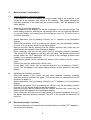
1.
General
The ETR 90 / 92 temperature control unit is an ultra-modern micro-processor
device. It provides a large number of functions but takes up very little space.
Great importance was placed during its development on making it easy to
operate.
These instructions contain all the information necessary for starting up and
operating this unit.
It is set in the factory at a number of settings which will be fully adequate for all
normal applications. However, if you wish to change any of them you will need to
change the configuration of the unit.
You can see how to do this from the separate set of instructions on configuration.
For the normal user, the configuration is "locked away" inside the unit by means
of a wiring bridge. The configuration should only be changed by knowledgeable
experts.
1.1
Technical data
Micro-processor control unit for two
temperature zone
Interface
Serial 150 to 19200 Baud via module as:
- passive 20 mA current loop (TTY)
- passive 20 mA current loop (TTY) 4-wire
- RS232 interface
- RS485 interface
A choice of protocols is available.
Size: 48 x 96 mm, 190 mm deep (to comply
with DIN 43700)
Mains power supply
230 V, 50 / 60 Hz (± 10 %), convertible to 115
V AC.
Input: 1 measurement sensor
Fe.CuNi (L):
0 - 500°C (32 - 900°F)
Fe.CuNi (J):
0 - 500°C (32 - 900°F)
Ni-CrNi (K):
0 - 900°C (32 - 1300°F)
Pt 100: 0 - 500°C (32 - 900°F)
Required value entry
Digital via keyboard or interface
Actual value display Digital via 7-segment display
The unit complies with DIN 43700 and DIN IEC
574
Automatic temperature compensation
Protected against sensor breakage and
reversing of poles.
Control panel
Two 4-figure 7-segment displays (required and actual
values)
One 1-figure 7-segment information display
Six status LED's, 4 keys, foil covered
Input 2 can at choice also be used for
monitoring electric current via a current
converter or addressing resistance in interface
operation.
Control behaviour
Extended digital PID algorithm, separate for heating and
cooling, automatic structure change-over (PD, PID, PI).
Approach adaptation to parameter requirement in the
approach phase, facility for manually reading out and
adjusting control parameters.
Outputs:
Output 1 Heating Zone 1
Output 2 Cooling or Alarm Zone 1
Output 3 Heating Zone 2
Output 4 Cooling or Alarm Zone 2
- Open collector 9V / 20 mA for thyristor or
solid-state relays
- Solid-state relay 230 V AC / min 10 mA, max.
100 mA for output protection
- Analogue 0 - 10 V or 0 - 20 mA for constancy
actuators (Outputs 2 + 4 only Cooling)
Housing
Robust, shock-resistant steel plate housing
Insulation tension
Mains electronics: 1.5 kV
Test voltage: 2.5 kV
Connecting terminals
16-pole screw terminals, maximum 1.5
1
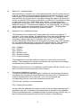
2.
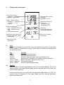
Display and control panel
Actual value (normal
operation)
Parameter - abbreviation
Required value (normal
operation)
Parameter - value
Status - display (yellow)
o = heating, * = cooling
1 = channel 1, o = no
function
< >
A
Alarm message (red)
(= GW-, temperature too low)
= GW+, temperature too
high
A = Mains power alarm
Information display for:
- unit (C, F)
- Operator's list (L)
- parameter list (P)
Scroll key
(call up Operator's List,
"scrolling" parameter)
Manual key with yellow LED
(controller operation, power
acceptance)
"More" key (increase
parameter)
"Less" key (reduce
parameter)
2.1
Keys
A function is allocated to each of the keys, and additional functions can be called
up by means of combinations of keys. These can be selected by pressing two
keys simultaneously.
Key
<More>
<Less>
<Scroll>
<Manual>
<Scroll / Less>
<Scroll / Manual>
<Scroll / More>
2.2
Function
Enlarges parameter value
Reduces parameter value
Scrolls to next parameter; calls up Operator's List
Switches from automatic to controller (manual) operation
Back to the basic "standard mode" level
Call up parameter list
Scrolls to preceding parameter
Displays
The unit has two 4-figure digital displays and one information display. The actual
value is shown in the upper digital display and the required value in the lower one
(when in basic position).
If values are entered in the control unit, the parameter abbreviation (e.g. "Set" for
required value) is displayed in the upper display and the relevant parameter
value in the lower one.
2
The information display shows which operating level has been selected. In the
basic position, the units (°C or °F) are displayed here. Other information displayed here is:
L = Control unit is in the "Operator's List" mode
°L = Entry bar has been removed on the Operator's List
P = Control unit is in the "Parameter List" mode
°P = Entry bar has been removed on the Parameter List
The entry bar is lifted when an additional dot is displayed at top left (this does not
apply when °C or °F is displayed).
2.3
Status LED's
The unit has 6 LED's, which indicate the following:
- Output display
Yellow LED's for automatic heating and cooling outputs. The LED Is off when the
heating / cooling is switched off; if it comes on and remains on, heating / cooling
is running at the maximum rate. Flashing indicates the relevant gradient between
0 % (off) and 99 % (on).
- Alarm message
The red LED's are on when there has been an alarm. <= Alarm 1 (e.g. limit value
minus, >= Alarm 2 (limit value plus), A = mains power alarm (e.g. when heating
current is being monitored).
- Manual
The yellow LED with a picture of a hand is off when the unit is running on
automatic. It comes on when the unit is in manual (controller) operation. In
adaptation mode, i.e. when the unit is calculating the parameters for automatic
operation, the LED with the hand flashes.
3.
Operation in general
It is important to know all the general operational steps in order to be able to use
this unit without difficulty. These are described in this section.
3.1
Operator levels
In order to separate the major settings from the minor ones, the unit is divided
into three operator levels.
3
a)
Base level - standard mode
After switching on, the device is in this operating mode. Here the actual value of
channel 1 is shown in the upper display and the actual value of channel 2 in the
lower display. The information display indicates the unit °C. From every other
operator level, the device returns to this base setting after approx. 30 seconds if
no key is activated. With the key combination <scroll/less> it is possible to return
to base level at any time. Within base level, channel 1 can be scanned by
pressing the <scroll> key once. If the <scroll> key is activated again, there is a
switch to channel 2. The actual value appears in the upper display, the required
value for the respective zone appears in the lower display. The information
display then shows the corresponding channel number.
b)
Operator's List / standard functions
The Operator's List is called up by holding down the <scroll> key (approx. 2
seconds). In the upper display, the abbreviation for the selected parameter now
appears, with the corresponding parameter value in the lower display. The
information display shows an "L" (Operator List) and a "1" or "2" (channel
number) alternately. When there is a change from the base level to the operator
list, the channel last selected in the base level remains actual. The Operator's
List consists of the following parameters per channel, at the maximum:
Grd = Gradient
AL1 = Alarm 1
AL2 = Alarm 2
ACr = Actual current
RCr = Required current
CrT = Current tolerance.
The parameters that can be called up varies from one version of the unit to
another. The parameters for current, for instance, are only active if the heating
current monitoring facility has been built in.
Within the Operator's List, it is possible to scroll forwards with the <Scroll> key, or
back to the previous parameter with <Scroll / More>.
c)
Parameter list/additional functions
In order that additional parameters can be calaled up, the parameter list has to
be called up by pressing the <Scroll/Manual> keys both at once. Depending on
whether the parameter list for channels 1 or 2 is to be selected, the
corresponding channel must first be selected at base level.
From this list, normally only the parameter.
Grd = Temperature gradient
can be called up, although with certain version of the unit other parameters can
be called up as well. A complete list of parameters is included in the Appendix.
Within the parameters list it is possible to page forwards with the <Scroll> key, or
back to the previous parameter with the key comination <Scroll/More>.
4
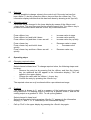
3.2
Entry bar
It is only possible to change values in the control unit if the entry bar has first
been raised. To do this, press the <More> key and then the <Less> key. The
information display indicates that this has been done by showing a dot (top left).
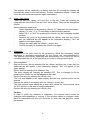
3.3
Changing values
Paramters can be changed in the lower display by means of the <More> and
<Less> keys. The entry bar must first be raised to permit this. The <More> key is
pressed to increase values and the <Less> key to decrease them.
Press <More> key
Press <More> key and hold it down
Press <More> key and then <Less> as well
=
=
=
increase value in steps
increase value quicikly
increase value very quickly
Press <Less> key
Press <Less> key and hold it down
quickly
Press <Less> key and then <More> as well
quickly
=
Decrease value in steps
=
Decrease value
=
Decrease value very
4
Operating steps
4.1
Changing required values
Select channel at base level. To change required value, the following steps must
be taken:
Remove the entry bar by pressing first the <More> and then the <Less>
key (an additional dot will appear in the information display). "Set" will
appear in the upper display.
Change the value with the <More> / <Less> key.
Confirm the entry by pressing the <Scroll> key.
The required value can only be altered within a pre-determined range.
4.2
Gradient
The gradient is shown in %, and is a measure of the heating or cooling output
being achieved. Full heating output is shown as a gradient of 99%, and the full
cooling output as a gradient of -99%. To call up the gradient:
-
Select channel in base level.
Select the Operator's List by pressing <Scroll> ("L" appears in the information
display) ("L" and "1" or "2" alternately in the information display).
-
Call up "Grd" in the upper display by pressing the <Scroll> key again.
5
The gradient will be continually up-dated, and after 30 seconds the display will
automatically return to the basic setting. The key combination <Scroll / Less> will
return the unit to the basic position again immediately.
4.3
Alarm / limit values
There are two limit values, AL1 and AL2, in the unit. These will normally be
interpreted as Limit Value Plus and Limit Value Minus. They can be changed as
follows:
Select channel in base level.
Select Operator's List by pressing <Scroll> ("L" appears in the information
display) ("L" and "1" or "2" alternately in the information display).
Select "AL1" or "AL2" by pressing the <Scroll> key the necessary number
of times
Remove the entry bar by pressing first the <More> and then the <Less>
key (an additional dot will appear in the information display). "Set" will
appear in the upper display.
Change the value with the <More> / <Less> key.
Confirm the entry by pressing the <Scroll> key again.
4.4
Adaptation
Adaptation is the term used for the process by which the necessary control
parameter is calculated automatically for the control unit ("self-optimisation").
This process runs entirely separately and automatically, but it has to be set off
manually when the unit is first started up on a new or change control point.
a)
-
Start adaptation
Remove the entry bar by pressing first the <More> and then the <Less> key (an
additional dot will appear in the information display). "Set" will appear in the
upper display.
Select "AdA" by pressing the <Manual> key.
The lower display will normally be showing OFF. This is changed to ON by
pressing the <Less> key so that adaptation can start.
Confirm the entry by pressing the <Scroll> key.
"Set" will now appear in the upper display and the new required value can be
entered.
Change the value (if necessary) with the <More> / <Less> key.
The new required value should be at least 40°C above the current actual value
(or 30°C below it in the case of cooling adaptation).
Confirm the entry by pressing the <Scroll> key.
-
Caution:
In order to avoid any mistakes in adaptation, the required value cannot be
changed while adaptation is running. If the required valued is changed, adaptation is suspended and the unit continues to work with the previous control
parameters.
6
b)
Terminating adaptation
The adaptation cycle automatically comes to an end when the parameters have
been calculated. It is not normally necessary to terminate.
-
Remove the entry bar by pressing first the <More> and then the <Less> key (an
additional dot will appear in the information display).
Select "AdA" by pressing the <Manual> key.
Change "ON" in the lower display to "OFF" by pressing the <Less> key.
Confirm the entry by pressing the <Scroll> key.
-
7
5
Main functions / explanations
5.1
Sensor breakage / controller operation
In the event of a sensor breaking, the region under control can continue to be
controlled at the gradient last saved in the memory. This makes emergency
operation possible. If the lead from the sensor breaks, "Sb" will appear in the
upper display.
a)
Switching to controller operation
If "Sb" appears in the display, the sensor connected to the unit has broken. The
lower display goes out, and the pre-set required value can no longer be adjusted.
If a sensor breaks, the heating and the cooling are shut off. To switch over to
controller operation:
-
Select Operator's List by pressing <Scroll> (an "L" appears in the information
display).
Select the parameter "Grd" by pressing the <Scroll> key the necessary number
of times, it is not already shown in the upper display.
Remove the entry bar by pressing first the <More> and then the <Less> key (an
additional dot will appear in the information display).
Press <Manual> and the unit will switch over to controller (manual) operation.
The yellow LED will appear in the key with the hand. The gradient issued and
shown under the "Grd" parameter will be equal to the average gradient most
recently run in automatic operation.
The gradient issued can be corrected by means of the <More> and the <Less>
keys.
Confirm the entry by pressing the <Scroll> key.
At the basic level, which can be reached with the key combination <Scroll /
Less>, "Sb" will appear in the upper display and the current gradient in the lower
display.
-
-
b)
-
5.2
Switching off controller operation
When the sensor of the control unit has been repaired, controller (manual)
operation must be switched off again. This can be done by switched the unit off
and then on again, or:
Select Operator's List by pressing <Scroll> (an "L" appears in the information
display).
Select the parameter "Grd" by pressing the <Scroll> key the necessary number
of times, it is not already shown in the upper display.
Remove the entry bar by pressing first the <More> and then the <Less> key (an
additional dot will appear in the information display).
Press <Manual> and the unit will switch back to automatic operation, but only if
the sensor has been properly repaired. The LED in the key with the hand will not
come on.
Reversed polarity of sensors
If a thermoelement is connected with reversed polarity, the letters "FP" appear in
the actual value display.
8
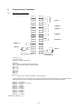
6.
Commissioning / installation
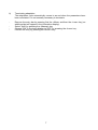
6.1
Allocation of terminals
17
1
L1
18
2
SL
19
3
N
20
4
-
21
5
+
22
6
-
23
7
+
24
8
-
25
9
+
26
10
+
27
11
-
interface
28
12
29
13
+
30
14
-
31
15
-
input 1
32
16
+
-
output 4
+
input 2
thermocouple as input 1
power
output 1
output 2
output 3
thermocouple
Fe-CuNi/ NiCr-Ni
1) Outputs 1, 2, 3
TS, constant or SSR
With TS and constant, check polarity
2)Interface
With TTY (20 mA) 2-lead and RS485, as illustrated.
With TTY (20 mA) 4-lead, output 3 is used for interface
RXD + on 8
RXD - on 9
TXD + on 10
TXD - on 11
With RS232:
GND on 9
TXD on 10
RXD on 11
3)
Input 2, current converter connection for monitoring current
In interface operation and current monitoring, the control unit address is set via keyboard on the unit. In interface operation
without monitoring of current, resistances can be addressed via the current inputs. The following values apply:
Address 0 = no resistance
Address 1 = terminals 12 + 13 bridged
Address 2 = 1.3 kOhm
Address 3 = 1.78 kOhm
Address 4 = 2.87 kOhm
Address 5 = 3.92 kOhm
Address 6 = 5.11 kOhm
Address 7 = 6.81 kOhm
Address 8 = 8.06 kOhm
Address 9 = 11.5 kOhm
Address 10 = 14.3 kOhm
..
All resistances: metal layer < 1%
9
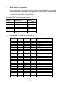
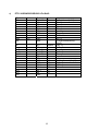
7
Works settings / parameters
The units are set in the works at values which will be suitable for most normal
areas of operation. For the sake of completeness, however, these works settings
are listed below and if any changes have to be made a separate set of
configuration instructions can be provided.
Operator's List L: (for all standard versions)
Symbol
Explanation
Set
Grd
AL1
AL2
Acr
CrT
RCr
Required value
Gradient
Alarm 1
Alarm 2
Actual current
Current tolerance
Required current
a)
Setting
Units
020
°C
00
%
010
°C
010
°C
00.0
A
05.0
A
00.0
A
ETR 90 / SR / 0 / GSR / 500°C / Fe / O / O
Symbol
Pb
Td
Ti
Ta
Pb
TdTiTaAdA
Adr
Attribute
--------AP
--
Setting
2.0
15
60
10
3,0
120
10
OFF
000
9.6
Units
%
sec
sec
sec
%
sec
sec
sec
bd
Pro
btA?
Sys?
Adp?
Sb
SbSoo
Sou
rAP
AS1
AS2
OFF
Sen
---------------
00
look 1)
look 2)
look 3)
99
99
500
000
00.0
A3.1
A2.1
00
FEL
kbaud
%
%
°C
°C
°C/min
°C
°C
°C
10
1) Betriebsart (btA?)
St = 0
St- = 0
rE = 1
rE- = 0
lin = 0
FbA = 0
PAS = 0
3P=0
2) Systemeinstellung
(Sys?)
CEL = 1
SbF = 0
Su = 0
An4 = 0
Par = 0
tsp = 0
3) Adaptionsart (Adp?)
Apb = 1
AAF = 0
AA- = 0
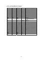
b) ETR 90/TS/0/GSR/500°C/Fe/StA/0
Symbol
Pb
Td
Ti
Ta
Pb
TdTiTaAdA
Adr
Attribute
--------AP
--
Setting
1.0
10
40
00
3,0
30
120
10
OFF
000
Units
%
sec
sec
sec
%
sec
sec
sec
bd
Pro
btA?
Sys?
Adp?
Sb
SbSoo
Sou
rAP
AS1
AS2
OFF
Sen
---------------
9.6
99
look 1)
look 2)
look 3)
99
99
500
000
00.0
A3.1
A2.1
00
FEL
kbaud
%
%
°C
°C
°C/min
°C
°C
°C
11
1) Betriebsart (btA?)
St = 0
St- = 0
rE = 1
rE- = 0
lin = 0
Fba = 0
PAS = 0
3P = 0
2) Systemeinstellung
(Sys?)
CEL = 1
SbF = 0
Su = 0
An4 = 0
Par = 0
tsp = 0
3) Adaptionsart (Adp?)
Apb = 1
AAF = 0
AA- = 0
c)
ETR 90/SR/KSR/GSR/500°c/Fe/StA/0
Symbol
Pb
Td
Ti
Ta
Pb
TdTiTaAdA
Adr
Attribute
--------AP
--
Setting
2.0
15
60
10
3,0
30
120
10
OFF
000
Units
%
sec
sec
sec
%
sec
sec
sec
bd
Pro
btA?
Sys?
Adp?
Sb
SbSoo
Sou
rAP
AS1
AS2
OFF
Sen
---------------
9.6
00
look 1)
look 2)
look 3)
99
99
500
000
00.0
A3.1
A2.1
00
FEL
kbaud
%
%
°C
°C
°C/min
°C
°C
°C
12
1) Betriebsart (btA?)
St = 0
St- = 0
rE = 1
rE- = 1
lin = 0
Fba = 0
PAS = 0
3P = 1
2) Systemeinstellung
(Sys?)
CEL = 1
SbF = 0
Su = 1
An4 = 0
Par = 0
tsp = 0
3) Adaptionsart (Adp?)
Apb = 1
AAF = 0
AA- = 0