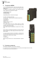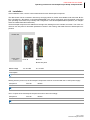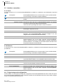
1
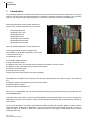
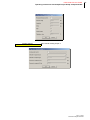
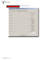
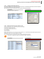
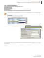
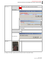
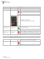
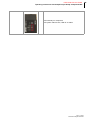
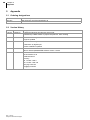
Operating Instructions Project Setup of Component MPI02 Temperature Control System Rev.1.00.03 04/2014 Translation of original operating instructions 1 PSG Plastic Service GmbH Operating Instructions flexotemp® Project Setup Component MPI Chapter 1 Introduction 2 Typographical Conventions Additional and continuative documents 3 4 Chapter 2 Prerequisites 5 Chapter 3 Examples 5 Chapter 4 Component MPI02 6 Necessary components Installation Interface connection Serial Ethernet Project setup and configuration Create controller and components Configure component Configure component by Wizard Configure component by parameter and/or configurator Configure measurement input 1/2 Specify limit value and alarm output on relay Configure analog output 1/2 Inputs X1 Calibration inputs Calibration of connected pressure transducer Status Status Parameter / Configurator Status I/O Chapter 5 Appendix Ordering designations Version History 6 7 8 8 8 8 9 12 12 15 19 19 21 22 22 23 25 25 25 30 30 30 Rev. 1.00.03 Subject to technical changes 2 Chapter 1 Introduction 1 Introduction This operating instructions introduces the multi loop control system flexotemp® with its components. The system structure and the project planning/configuration is described by practical examples completely. The necessary steps, to work with the system safely and quickly, can easily be derived by these specific applications. Multi loop temperature control system flexotemp® based on the controller and open loop control units flexotemp® MCU 128 flexotemp ® PCU 128 flexotemp® PCU 48 flexotemp® PCU 24 flexotemp® PCU 128 PNIO flexotemp® PCU 48 PNIO flexotemp® PCU 24 PNIO allows an optimal adaptation for each requirement. Consequent modular design of intelligent IOs, the possibility of peripheral configuration in I/O nodes, universal function range are guarantors for this. The available digital interfaces serial data interface COM CANopen slave CAN1 for controller internal network and network to superior control CANopen master CAN2 (field bus) for external I/O modules Profibus DP interface L2-DP Ethernet interface TCP/IP provide easy internal and external connection possibility. PROFINET IO is available for the controller and open loop unit labeled with the mnemonic PNIO . The interfaces are: CANopen master CAN2 (field bus) for external I/O modules Ethernet interface TCP/IP Ethernet interface PROFINET IO The ways of communication and the system structure are defined by the project planning and configuration tool flexotempMANAGER. These directions assist, both in case of the initial installation and operational startup, and in case of changes and adaptations to existing control systems. Status and fault signals are described and remedial actions proposed for their removal. The protocol descriptions for PSGII, PSGII Ethernet (ASCII), Profibus DP, Modbus, Modbus TCP/IP, Profibus DPEA, CANopen, Send/Receive, PROFINET IO are not a component part of the operating manual. You are provided with these on request or directly as a download from the home page of PSG Plastic Service GmbH (www.psg-online.de). Rev. 1.00.03 Subject to technical changes PSG Plastic Service GmbH Operating instructions flexotemp® Project Setup Component MPI 1.1 Typographical Conventions Symbols and conventions are used in this manual for faster orientation for you. Symbols Caution With this symbol, references and information are displayed which are decisive for the operation of the device. In case of non-compliance with or inaccurate compliance there can result damage to the device or injuries to persons. Note The symbol refers to additional information and declarations, which serve for improved understanding. Example With the symbol, a function is explained by means of an example. Reference With this symbol, information in another document is referred to. FAQ Here FAQ (Frequently Asked Questions) are answered. Cross references are marked with the character f. In the pdf version of the document the objective of the cross reference is reached via the link. Equations Calculation specifications and examples are represented in this way. <View> Menu points (e.g. view) are represented in this way. |Project| Windows (e.g. project) are represented in this way. n.a. Not applicable, not existing Rev. 1.00.03 Subject to technical changes 3 4 Chapter 1 Introduction 1.2 Additional and continuative documents Parameters Information on this topic are in the operating instructions Temperature Control System flexotemp® Parameter zu entnehmen. Operation Information on this topic are in the operating instructions Project Planning and Configuration Tool flexotempMANAGER Operation zu entnehmen. Protocol PSG II Protocol PSG II Ethernet (ASCII) Protocol Profibus DP Protocol Modbus Protocol Modbus/TCP Protocol Profibus DPEA Protocol PROFINET IO Protocol CANopen Data sheet Rev. 1.00.03 Subject to technical changes Information on this topic are in the protocol description PSG II and the corresponding object lists. Information on this topic are in the protocol description PSG II Ethernet (ASCII) and the corresponding object lists. Information on this topic are in the protocol description Profibus DP and the corresponding object lists. Information on this topic are in the protocol description Modbus and the corresponding object lists. Information on this topic are in the protocol description Modbus/TCP and the corresponding object lists. Information on this topic are in the protocol description Profibus DPEA and the corresponding object lists. Information on this topic are in the protocol description PROFINET IO and the corresponding object lists. Information on this topic are in the protocol description CANopen and the corresponding object lists. The data sheets can be accessed in Internet by www.psg-online.de, and/or are available under menu bar <Extras> <Options> <Update> in flexotempMANAGER in the project view below each flexotemp® component (see operating instructions Project Planning and Configuration Tool flexotempMANAGER Operation). PSG Plastic Service GmbH Operating instructions flexotemp® Project Setup Component MPI 2 Prerequisites For installation and project planning of flexotemp® components, the following prerequisites must be fulfilled: the project planning and configuration tool flexotempMANAGER is installed on a PC as standard installation the flexotempMANAGER and the communication server (PSGCommServer) are running on the same computer hardware. Are other communication concepts employed, one has to answer the following questions where is the flexotempMANAGER running? where is the communication server (PSGCommServer) running? how are the controllers connected? In chapter Communication Concepts of flexotempMANAGER in the operating instructions Project Setup and Configuration Tool flexotempMANAGER Operation (see Prerequisites) is described, which settings must be made in the flexotempMANAGER for PSGCommServer and master components (MCU/PCU). Information on addressing an CAN-bus termination please see the operating manual for Temperature Control System flexotemp® , System Configuration & Project Setup (see Prerequisites). Further details, how the project planning and configuration tool flexotempMANAGER should be used and operated, as well as further explanations of the parameters, please see the operating instructions (see chapter Prerequisites). 3 Examples In the following example a component is described, with the target, to combine it with other flexotemp® components to a operational project and implement it in the project setup/configuration in flexotempMANAGER. Each example is divided by the following points Necessary components: List of the required flexotemp® components for the project Installation: the configuration and wiring of the flexotemp® components Interface connections: establishing of connection between flexotemp® components with flexotempMANAGER serial/per Ethernet Project planning and configuration: the settings for the project in flexotempMANAGER, the parameters to configure, inclusive addressing of components The necessary steps for own applications, to work with the system safely and quickly, can easily be derived by these exemplary configuration and project planning. Rev. 1.00.03 Subject to technical changes 5 6 Chapter 4 Component MPI02 4 Component MPI02 The component Melt Pressure Input flexotemp® MPI02 determines 2 measured value of standard strain gauge pressure transducers. The MPI02 is an autarkic CANopen node module, that determines, analyzes and outputs all in-/outputs 2 Measurement inputs 4 Alarm outputs 2 Analog outputs selbstständig erfasst, auswertet und ausgibt. The alarm monitoring determines 8 Limit values ?(absolute pressure/differential pressure) 1 Hysteresis Peak Detection System error Errors in measuring circuit Calibration error The 4 alarm outputs and the 2 analog outputs (0...20mA/ 4...20mA) can freely be assigned to the measurement inputs (absolute-/differential pressure). On the alarm outputs combinations of alarms can be configured. Each channel is monitored permanently by sensor break and error on current loop. LED's display this and the status of the 4 alarm outputs. The signal analysis is directly on the module; no measured values and status information is led to the superior flexotemp controller unit. By the Direct IO's the status of inputs of the module and of the inputs itself can be communicated with a superior PLC. 4.1 Necessary components The following flexotemp® components are required: 1 Peripheral Control Unit flexotemp® PCU (controller) (in the example PCU 48 is used) 1 Melt Pressure Input flexotemp® MPI 02 Rev. 1.00.03 Technical changes reserved PSG Plastic Service GmbH Operating instructions flexotemp® Project Setup Component MPI 4.2 Installation At all installation work, note the current data sheets for each flexotemp® component. The data sheets can be accessed in Internet by www.psg-online.de, and/or are available under menu bar <Extras> <Options> <Update> in flexotempMANAGER in the project view below each flexotemp® component (see operating instructions Project Setup and Configuration Tool flexotempMANAGER Operation, see Ergänzende und weiterführende Dokumente). The flexotemp® components are added from the right side, starting from the controller, as shown. The cross connections click into place for automatic parallel bus contact in the housing, that builds a block of flexotemp® components. Power unit Output voltage 24 VDC PCU 48 MPI02 click into place Rated voltage 18...30 VDC 18...30 VDC Power consumption 6W <5W See current data sheets Starting with the power unit, the flexotemp® components must be connected with the 24 VDC power supply. Component Terminal PCU 48 MPI02 X1 <n.a.> See current data sheets The in-/outputs of the flexotemp® components must be wired accordingly. Component Terminal PCU 48 MPI02 <n.a.> X1, X2 See current data sheets Rev. 1.00.03 Technical changes reserved 7 8 Chapter 4 Component MPI02 4.3 Interface connection 4.3.1 Serial A serial connection to PC, where flexotempMANAGER is installed, is created from the flexotemp® component PCU48. Prerequisite flexotempMANAGER and the communication server (PSGCommServer) are running on the same computer hardware. Prerequisite flexotemp® component PCU48 has the option COM interface RS232/ RS422. PC side Interface converter Due the fact, that a PC has no standard RS485 interface, an interface converter is required (see data sheet SK232485). Take care of the pin assignment and the correct connection. Controller side The RS232 cable must be connected to the connection X5 COM of the flexotemp® component PCU48. PSGCommServer Create a serial interface (operating instructions Project setup and Configuration Tool flexotempMANAGER Operation chapter 3.1.2, see Ergänzende und weiterführende Dokumente). flexotempMANAGER Check on the side of the communication server, that the setting <The PSGCommServer runs on the same computer as flexotempMANAGER> is selected. By the key <Read setting of interface manually by PSGCommServer>, the settings of the serial interface are taken from the previous step and can be selected. 4.3.2 Ethernet A connection to PC, where flexotempMANAGER is installed, is created from the flexotemp® component PCU48 per Ethernet. Prerequisite flexotempMANAGER and the communication server (PSGCommServer) are running on the same computer hardware. PC side LAN connection For direct coupling from PC and controller, use a cross-over cable. Using a Fast-Ethernet-Switch, use a standard Ethernet network cable. Controller side The Ethernet network cable must be connected to the connection X2 TCP/IP of the flexotemp® component PCU48. flexotempMANAGER Check on the side of the communication server, that the setting <The PSGCommServer runs on the same computer as flexotempMANAGER> is selected. 4.4 Project setup and configuration Further details, how the project planning and configuration tool flexotempMANAGER should be used and operated, as well as further explanations of the parameters, please see the operating instructions (see chapter Ergänzende und weiterführende Dokumente). Rev. 1.00.03 Technical changes reserved PSG Plastic Service GmbH Operating instructions flexotemp® Project Setup Component MPI 4.4.1 Create controller and components Prerequisite flexotempMANAGER is installed on PC. Prerequisite flexotempMANAGER and the communication server (PSGCommServer) are running on the same computer hardware. The flexotemp® components are configured in the order shown in Installation (from the left, starting from the controller, to the right). PC side flexotempMANAGER Symbol bar: <View> Symbol bar, Status bar, Project are active. start Menu bar: <File> <New>. No project (<Unnamed>) is displayed. Rev. 1.00.03 Technical changes reserved 9 10 Chapter 4 Component MPI02 Create controller Create controller PCU048 by <Create new component>. Address setting The setting of the device ID on the coding switch here and on the rotary switch on the controller must fit. At communication by Ethernet, the PC must have the same subnet like the controller (subnet mask: 255.255.255.0). Controller PCU048 is created. Rev. 1.00.03 Technical changes reserved PSG Plastic Service GmbH Operating instructions flexotemp® Project Setup Component MPI Create further components Beneath the controller, the further component MPI02 is selected out of a list and created. The controller and the component MPI02 is created in the project. The project is stored with the name Example_MPI02 and transferred to the controller. Rev. 1.00.03 Technical changes reserved 11 12 Chapter 4 Component MPI02 4.4.2 Configure component The component is described by menu item Parameter, Wizard/Configurator, Inputs X1 and Calibration Inputs. Parameters for the component MPI02 can be entered by a Wizard (guided data entry), with a predefined model for parameterization of pressure transducer and following calibration parameters directly a configurator By the context menu of component MPI02 (select the component in the project and secondary mouse button) the original setting of the parameters can be reset by <Write delivery status> (operating instructions Temperature Control System flexotemp® Parameter see Additional and continuative documents). 4.4.3 Configure component by Wizard By configuration by Wizard, a predefined model for parameterization of pressure transducers is used. Only the measurement range of the pressure transducer a correction of the pre- and/or main alarms (when not full scale range) low-active, storing display of sensor break, calibration error can be set by the operator, the remaining parameters are defined by default values. A calibration follows. To set other parameters, see Configure component by parameter and/or configurator. By Wizard MPI02 Wizard Selection of channel 1 or channel 2 or both channels. Is only one channel selected, the other channel is removed from the display. Rev. 1.00.03 Technical changes reserved PSG Plastic Service GmbH Operating instructions flexotemp® Project Setup Component MPI The measurement range must be defined for the selected channels (see messages) The measurement range is adjusted to 500 bar for channel 1/2 in the example. Setting of pre-alarm The pre-alarm is adjusted to 400 bar for channel 1/2. Please note the specifications in the menus, where alarms are output and parameters are stored. Rev. 1.00.03 Technical changes reserved 13 14 Chapter 4 Component MPI02 Setting of main alarm The main alarm is adjusted to 450 bar for channel 1/2. Please note the specifications in the menus, where alarms are output and parameters are stored. All entries are finally listed and can be transferred into the project setup and to the component by <Data transfer?>, when a component is connected. In this example the data can only be transferred into project setup. flexotempMANAGER has determined, that no component is connected, where the data can be transferred to. The operator can remove the check to change the pre-selection by the program. The dialog is finished after this step, because no component is connected. Rev. 1.00.03 Technical changes reserved PSG Plastic Service GmbH Operating instructions flexotemp® Project Setup Component MPI Is a component connected, and the data transfer to component finished successfully, the calibration of MPI02 can be started afterwards. Actions and messages of status see Calibration of connected pressure transducer. 4.4.4 Configure component by parameter and/or configurator By Parameter Configure measurement input 1/2 M2210...M2216 for AI 1/2 M2220, M2221 or Specify limit value and alarm output M2222, M2223 or ... on relay M2234, M2235 By Configurator Measurement input 1/2 Alarm output n (n defines relay 1...4) M2240 for Rel1...4 Configure analog output 1/2 M2203...M2206 for AO 1/2 Analog outputs 1/2 For a detailed description of the single parameters see operating instructions Informationen zu diesem Thema sind der Bedienungsanleitung Temperaturregelsystem flexotemp® Parameter. Rev. 1.00.03 Technical changes reserved 15 16 Chapter 4 Component MPI02 By Parameter A list with all parameters is displayed. <View> <Project> Component MPI02 - Parameter By Configurator <View> <Project> Component MPI02 - Configurator Measurement input 1 Rev. 1.00.03 Technical changes reserved Also valid for measurement input 2 PSG Plastic Service GmbH Operating instructions flexotemp® Project Setup Component MPI Analog Output 1 Also valid for analog output 2 Rev. 1.00.03 Technical changes reserved 17 18 Chapter 4 Component MPI02 Alarm output 1 Rev. 1.00.03 Technical changes reserved Also valid for alarm output 2-4 PSG Plastic Service GmbH Operating instructions flexotemp® Project Setup Component MPI 4.4.4.1 Configure measurement input 1/2 The pressure transducer is connected to a measurement input. The standard specifications here must be adjusted to the technical data of the pressure transducer. (See operating instructions Temperature Control System flexotemp® Parameter) By Parameter Measurement input 1 (input AI 1) By Configurator Measurement input 1 4.4.4.2 Specify limit value and alarm output on relay A total of 8 limit values can be defined and for each limit value monitoring of absolute pressure monitoring of differential pressure or no monitoring can be specified. Beside system alarms (e.g. error CAN, limit value reached, etc.), channel-/input specific alarms (sensor break on measurement input 1, etc.) can be output on 4 relays. (See operating instructions Temperature Control System flexotemp® Parameter) Limit value 1 is adjusted to 450 bar for measurement input 1 (input AI 1) By Parameter By Configurator Alarm output 1 Rev. 1.00.03 Technical changes reserved 19 20 Chapter 4 Component MPI02 Alarm output on relay 1 for sensor break and limit value 1 reaches measurement input 1 (input AI 1). By Parameter By Configurator Alarm output 1 Sensor break (SB Sensor 1/2) and Current Loop (CL Analog output 1/2) are directly shown by the LED on the component. The status, that show the LED's of the relays (R1=A1.1, R2=A1.2, R3=A2.1, R4=A2.2), can be seen in the settings of the particular alarm output. Rev. 1.00.03 Technical changes reserved PSG Plastic Service GmbH Operating instructions flexotemp® Project Setup Component MPI 4.4.4.3 Configure analog output 1/2 In total 2 analog outputs can be configured, which output the absolute pressure the differential pressure as standard signal I. (See operating instructions Temperature Control System flexotemp® Parameter) On analog output 1 a measurement input 1 (input AI 1) proportional analog signal of 0...20mA is output. By Parameter By Configurator Analog Output 1 Is no analog output used, connect X2/1 with X2/2 and X2/3 with X2/4 and/or ignore the display of <Cur-rent Loop> see Status I/O. Rev. 1.00.03 Technical changes reserved 21 22 Chapter 4 Component MPI02 4.4.4.4 Inputs X1 By the inputs X1, the measurement inputs can be assigned to CoDeSys variables, which can be made available for a PLC programming by an export file as variable list. (See operating instructions Project Setup and Configuration Tool flexotempMANAGER Operation) Inputs X1 Measurement input 1/2 (input AI 1/2) 4.4.4.5 Calibration inputs By calibration inputs the functions Zero calibration Full scale calibration Calibration release Reset-acknowledge stored alarms can be combined with digital inputs and can control the components. The available digital inputs in the configuration (here only VDI; otherwise project setup of DIO16CI necessary) are offered in a list for selection. Is the calibration done by a digital input, the signal must be available for at least 2 s on this input (an edge is not sufficient). Rev. 1.00.03 Technical changes reserved PSG Plastic Service GmbH Operating instructions flexotemp® Project Setup Component MPI 4.5 Calibration of connected pressure transducer After project setup and configuration and transfer of the defined settings to the controller, the calibration of the connected pressure transducers must be executed. Change from |Project| to |Status| of component MPI02 in flexotempMANAGER. Dependent on the parameter [M2212] Shunt existing are/is two calibration keys ([M2212] = OFF) one calibration key ([M2212] = ON) shown. Is only one key available, first the zero calibration is executed and then the full scale calibration after connection of the shunt by relay (pressure transducer 1 X1/Cal13/Cal14 and/or pressure transducer 1 X1/Cal23/Cal24). After pressing of one of the keys, the function starts. After confirmation of the security query, that the function should be executed, the calibration is started. Rev. 1.00.03 Technical changes reserved 23 24 Chapter 4 Component MPI02 In the display below the keys(s), the possible actions and/or messages to the status are shown. Execute zero calibration Execute full scale calibration So far no calibration executed. Execute calibration <Calibration type>calibration not possible, For the selected calibration type, the value range (see due to measuring points outside value <Number of measuring points>) is not correct. range. The display remains for about ca. 5 seconds. Check setting and calibration At the check of the values set an error was detected. Check the values set (e.g., if [M2210] = 0) Sensor break Please check <Calibration type> started <Calibration type> running <Calibration type> finished <No display> Rev. 1.00.03 Technical changes reserved Calibration has been successfully carried out. A restart is possible, but not necessary. PSG Plastic Service GmbH Operating instructions flexotemp® Project Setup Component MPI 4.6 Status Component-relevant parameters, in-/outputs, and measured readings on the components as well as alarm status are displayed with their status. The display is updated consecutively, as long as the communication is <Online>. Contrary to the project, where the change of parameters must be explicitly written to the controller and/or read from the controller, in status accesses directly online the parameters in the controller (see operating instructions Project Setup and Configuration Tool flexotempMANAGER Operation chapter Status). 4.6.1 Status Parameter / Configurator On the status page under <Status Parameter> and <Status Configurator>, the parameters specified for the controller can be seen and set. The display is like described in chapter Configure component. 4.6.2 Status I/O On the status page under <Status I/O>, the in-/outputs, measurements and alarm status of the controller can be seen. Rev. 1.00.03 Technical changes reserved 25 26 Chapter 4 Component MPI02 Alarm red: alarm active LED display SYS A check sum error in the system data has occurred in the EEPROM. white: no alarm red: alarm active Component is not in pre-operational mode. LED display CAN red: alarm active Limit value LED display for limit value 1...8 Relay white: no alarm Relay symbol 1...4 Is the specified limit value reached, see chapter Specify limit value and alarm output on relay (limit value), it is signalized. white: no alarm black: relay contact open green: relay contact closed Rev. 1.00.03 Technical changes reserved PSG Plastic Service GmbH Operating instructions flexotemp® Project Setup Component MPI Key Alarm status Output relay 1...4 red: persistent alarm Signalizes, that at least one alarm is persistent. Press red key Plain text message, which persistent alarm is concerned. Plain text message, which stored alarm is concerned. A stored alarm can be reset/acknowledged, what removes the alarm from the display. Key white: no persistent alarm Press white key LED's directly component on LED yellow: alarm active LED off: no alarm For settings, see chapter Specify limit value and alarm output on relay (alarm output) Rev. 1.00.03 Technical changes reserved 27 28 Chapter 4 Component MPI02 Pressure Numerical value Current pressure value [unit bar] Min Peak Numerical value Smallest pressure value occurred [unit bar] Max Peak Numerical value Biggest pressure value occurred [unit bar] Sensor break LED display red: alarm active Is the specified limit value reached, see chapter Specify limit value and alarm output on relay (limit value), it is signalized. No display: no alarm LED's directly on component LED yellow: alarm active, LED off: no alarm Calibration active LED display green: calibration active No display: no calibration Calibration error LED display red: alarm active Reason: Calibration not executed (e.g. due to wrong settings see Calibration of connected pressure transducer) No display: no alarm Peak Reset Key Min Peak and Max Peak are reset to current pressure value. Current Numerical value Pressure value proportional current value [unit mA]; Settings see chapter Configure analog output 1/2 Sensor break LED display red: alarm active No display: no alarm Rev. 1.00.03 Technical changes reserved PSG Plastic Service GmbH Operating instructions flexotemp® Project Setup Component MPI LED's directly on component LED yellow: alarm active, LED off: no alarm Rev. 1.00.03 Technical changes reserved 29 30 Chapter 5 Appendix 5 Appendix 5.1 Ordering designations Order number Article description 025 057 Melt Pressure Input flexotemp® MPI 02 5.2 Version History Version Date Changes 1.00.03 4/30/2014 In detail the following amendments were made: Wizard step 5 Data transfer in project setup/device, when existing 1.00.02 11/3/2011 In detail the following amendments were made: Figures updated 1.00.01 10/28/2011 In detail the following amendments were made: Calibration by digital input Status calibration updated 1.00.00 04/09/2010 First edition Valid for flexotempMANAGER software version 1.02.00 PSG Plastic Service GmbH Pirnaer Straße 12-16 68309 Mannheim Germany Tel. +49 621 7162 0 Fax +49 621 7162 162 www.psg-online.de [email protected] Rev. 1.00.03 Subject to technical changes